
Submitted:
01 September 2025
Posted:
02 September 2025
You are already at the latest version
Abstract
The decarbonization of hard-to-defossilize sectors, such as international maritime transport, requires innovative, and at times disruptive, energy solutions that combine efficiency, scalability, and climate benefits. Therefore, power-to-liquid (PtL) routes have stood out for their potential to use low-emission electricity for the production of synthetic fuels, via electrolytic hydrogen and CO2 capture. The high energy demand inherent to these routes, however, poses significant challenges to large-scale implementation. Moreover, usually PtL routes are at most neutral in terms of CO2 emissions. This study evaluates, from a thermo-energetic perspective, the optimization potential of an e-methanol synthesis route through integration with a biomass oxy-fuel combustion process, making use of electrolytic oxygen as the oxidizing agent and the captured CO₂ as the carbon source. From the standpoint of a first-law thermodynamic analysis, mass and energy balances were developed considering the full oxygen supply for oxy-fuel combustion to be met through alkaline electrolysis, thus eliminating the energy penalty associated with conventional oxygen production via air separation units. The balance closure was based on a small-scale plant with a capacity of around 100 kta of methanol. In this integrated configuration, additional CO₂ surpluses beyond methanol synthesis demand can be directed to geological storage, which, when combined with bioenergy with carbon capture and storage (BECCS) strategies, may lead to net negative CO2 emissions. The results demonstrate that electrolytic oxygen valorization is a promising pathway to enhance the efficiency and climate performance of PtL processes.
Keywords:
alkaline electrolysis
; electrolytic oxygen
; oxy-fuel combustion
; biomass combustion
; power-to-liquid
; e-methanol
; carbon dioxide removal (CDR)
; carbon capture and utilization (CCU)
; process integration
1. Introduction
A power-to-liquid route can be understood as a chemical conversion process in which electrolytic hydrogen is combined with a carbon source, such as carbon dioxide, or, in a broader concept with a nitrogen source, to obtain a liquid compound with an energy purpose [1]. In other words, it is the conversion of electrical energy into chemical energy, materialized in the form of a synthetic fuel (e-fuel) capable of storing that energy within the bonds of its molecular structure.
Scientific interest in synthetic fuels is not essentially new. As early as the beginning of the 20th century, the Fischer–Tropsch synthesis was developed as an alternative for producing liquid hydrocarbons, particularly in a context of concern over external dependence on energy resources. This technology gained prominence during World War II, when Germany operated several plants capable of meeting most of its liquid fuel demand [2].
In the current context, however, research on synthetic fuels falls within a new paradigm marked by the energy transition and the pursuit of climate solutions. Unlike the original motivations related to oil self-sufficiency, the contemporary focus lies on mitigating the climate impacts caused by the intensive use of fossil fuels. In this regard, alternatives based on power-to-liquid routes stand out for their potential to employ low-emission electricity, such as solar or wind power, to produce synthetic fuels that are chemically analogous or identical to existing fossil options [3].
Thus, within the scope of climate mitigation policies led by organizations such as the IMO (International Maritime Organization), the adoption of e-fuels such as e-methanol for the decarbonization of international maritime transport has been widely discussed. This sector, typically classified as hard-to-defossilize, requires liquid fuels with high volumetric energy density, such as marine bunker or diesel, due to space constraints for cargo capacity in long-distance shipping ([4]). In this context, methanol emerges as a potential substitute, both for its compatible energy density and its adaptability for use in dual-fuel propulsion systems [5].
Therefore, the motivation for this study lies in the likely future relevance of e-methanol for hard-to-defossilize sectors and in the scalability challenges associated with the high energy demand of power-to-liquid routes. It also aims at valuing the oxygen obtained in the water electrolysis, whose use in an oxyfuel plant allows the production of an e-fuel with negative CO2 emissions (the CO2 emitted by the e-fuel combustion would be less than the carbon absorbed by the biomass that fuels the oxyfuel plant). Finally, since the oxyfuel plant provides part of the electricity required by the set of electrolysers, the integrated plant can be based on alkaline-electrolysers, whose minimum load is guaranteed by the biomass plant1.
In sum, this work aims to assess, from a thermo-energetic perspective, the proposed e-fuel route, which is based on the integration of water electrolysis with biomass oxy-fuel combustion process (equipped with CO2 capture). This route makes use of electrolytic oxygen as an input and captured CO₂ as the carbon source. The hypothesis is that such integration can reduce the energy penalties associated with conventional oxygen production and enable CO₂ surpluses for geological storage, thus configuring an arrangement with the potential for net negative emissions.
The originality of this study lies on the fact that the scientific literature on e-fuels, especially on PtL, usually focuses on assessing electrolytic processes and equipment emphasizing the hydrogen output [6,7], or on evaluating e-fuels whose carbon source derives from direct air capture (DAC) [8,9,10]. Few studies evaluate the use of electrolytic oxygen, such as the works of Kato et al. [11] and Mohammadpour et al. [12]. However, even those studies did not evaluate a whole integrated process for which the negative CO2 emission is relevant.
2. Materials and Methods
The aim of this article is the thermoenergetic analysis of a process based on a power-to-liquid route for methanol synthesis, aimed at valorizing electrolytic oxygen through the integration of this route with a biomass oxy-fuel combustion process. In this configuration, biomass oxy-combustion supplies not only part of the electricity required for electrolysis but also the CO₂ used in e-fuel production. An overview of the process is shown in the block diagram in Figure 1.
The system was modeled as three separate units: oxy-fuel combustion, electrolysis, and methanol synthesis. These were later linked using mass and energy balance results from the first law of thermodynamics applied to each control volume. The analysis assumes steady-state conditions, focusing on overall performance under constant operation and disregarding transient effects such as start-up or load variations. Efficiencies and conversions come directly from the simulation results, without additional losses beyond those in the models.
For the H₂ and CO₂ streams, high purity is assumed in line with values commonly reported for these technologies. Commercial alkaline electrolyzers typically deliver hydrogen with purity above 99.5% [13,14], while CO₂ from oxy-fuel combustion followed by cryogenic purification has been reported to exceed 99 mol% [15]. In the methanol synthesis block, the H₂ and CO₂ streams were treated as pure components, while their pressure and temperature at the inlet of this block were specified according to the outlet conditions of the respective upstream processes (electrolysis and biomass oxy-fuel combustion).
The logic for closing the mass balance among the three blocks shown in Figure 1 is guided by the target production of approximately 100 kta (kilo-tonnes per annum) of methanol, a value typical of small-scale plants [16]. This target sets the system’s hydrogen demand, which is supplied by alkaline electrolysis. The oxygen co-produced in the electrolysis is fully directed to the biomass oxy-fuel combustion process, which determines the required solid fuel consumption. The oxy-fuel combustion step generates more CO₂ than is needed for methanol synthesis; the surplus is accounted for as a stream intended for geological storage, as indicated in the results section, meaning that the methanol produced will also result in carbon dioxide removal (CDR) from the atmosphere.
The following subsections present each process block from Figure 1, namely biomass oxy-fuel combustion, alkaline water electrolysis, and methanol synthesis, describing the assumptions adopted, the use of simulation tools, and the calculations performed to build the integrated balance of this study.
2.1. Biomass Oxy-Fuel Combustion Unit Modeling
The oxy-fuel combustion stage was modeled using the Integrated Environmental Control Model (IECM) [17], a tool developed by Carnegie Mellon University for simulating thermoelectric plants integrated with different CO₂ capture options, providing detailed mass, energy, and cost balances for a variety of technological configurations. As discussed in the introduction to this section, this process block was structured to evaluate a thermochemical alternative for valorizing electrolytic oxygen, characteristic of power-to-liquid routes, with the additional advantage of generating the CO₂ used in methanol synthesis as well as part of the electricity required by the electrolysis block.
Accordingly, the model was configured to represent a Pulverized Coal (PC) plant in oxy-fuel mode, designed to operate with fuels containing less than 0.5 wt% sulfur, and adapted to use eucalyptus charcoal as the fuel. The characteristics of this fuel were obtained from the Phyllis2 database (https://phyllis.nl/Biomass/View/1956) and implemented in the IECM according to the elemental composition (ultimate analysis) and proximate composition (proximate analysis) values reported in Table 1.
Since the original data (columns 1, 2, and 3 of the table) were expressed on a dry basis, they were converted to an as received basis to represent a scenario closer to the industrial use of charcoal in metallurgical processes. For this conversion, a moisture content of 5 wt% was adopted, a value consistent with the range reported in the literature for commercial charcoal and also referenced in local regulations, such as Resolution SAA 10/2003 (Selo Premium). The adjustment was carried out by multiplying the original dry-basis values by a factor of 0.95 (1 – estimated original moisture fraction), applying the correction to both the proximate and ultimate analyses as well as to the calorific value (last column of Table 1). In this way, the compositions and energy values used in the model reflect as received conditions, incorporating the expected moisture content of the fuel in the oxy-fuel combustion process.
Given the scale characteristics of a biomass oxy-fuel combustion plant compatible with the proposed process, the base simulation was carried out by specifying a gross electrical output of 100 MWg, under South American ambient conditions (18.9 °C, 0.101 MPa, 50% relative humidity). The model was configured to include the main environmental controls associated with oxy-fuel technology: in-furnace NOₓ control, SO₂ control via a lime spray dryer and particulate removal by a fabric filter. CO₂ capture is performed through cryogenic purification, delivering the gas at approximately 13.79 MPa (137.9 bar), a condition suitable for direct use or storage.
To align the base model results with the specific conditions of this study, the mass and energy flows obtained were adjusted by linear scaling based on the actual availability of oxygen, which was determined specifically from the results of the alkaline electrolysis unit simulated using Aspen Plus, as detailed in the subsequent sections of this article.
Additionally, since the O₂ will be supplied by electrolysis, the internal consumption associated with the air separation unit was excluded from the balance, considering that the native IECM configuration assumes oxygen generation via a cryogenic ASU [17]. A simplified illustration of this native configuration is shown in Figure 2.
Finally, since the simulation results do not provide the initial and intermediate pressure conditions of the CO₂ purification unit for transport and geological storage, the fraction of this stream intended for the synthesis process, which requires a lower pressure than that for export, is adjusted through decompression processes handled specifically in the methanol synthesis block simulated using Aspen Plus – see Section 2.3.
2.2. Alkaline Electrolysis Unit Modeling
In the context of the power-to-liquid route, three main water electrolysis technologies for hydrogen production stand out [14], each with specific advantages and disadvantages [18]: (i) alkaline electrolysis, (ii) proton exchange membrane electrolysis, and (iii) solid oxide electrolysis. The selected technology for hydrogen production was alkaline water electrolysis, which, compared to the other alternatives, stands out as a more mature technology with a relatively low capital cost. This is due to the absence of noble metals as catalysts and simpler requirements in terms of structural design and equipment, although it requires auxiliary systems for separation and cooling [14]. This technology has been applied commercially on a large scale since the 1920s [19] and, in addition, operates at relatively low temperatures, typically between 60 °C and 90 °C.
Accordingly, the modeling of the alkaline electrolysis unit was developed in Aspen Plus with the objective of calculating the mass and energy balances required for this study. For this purpose, the simulation was based on Aspen’s native model representing the NEL A3880 industrial alkaline electrolyzer [20], which, through a rigorous model, allows for the detailed representation of the equipment’s design and operating parameters, making it useful for analyses aimed at optimizing operating conditions. The structure of the model used is represented in the process flow diagram shown in Figure 3.
In this study, the operating temperature was set at 80 °C, in line with typical operating parameters for alkaline electrolysis. As noted by Bi et al. [21], operating at higher temperatures can deliver significant efficiency gains. However, such gains are accompanied by a substantial increase in water consumption for the electrolysis reaction. More specifically, operation near 130 °C can result in efficiency improvements exceeding 10% compared to operation at 80 °C, but the associated water consumption can increase by approximately 60%, which may be incompatible with process configurations aiming to provide lower environmental impact.
Based on the hydrogen production results for a single electrolyzer unit, the mass and energy balances were adjusted by linear scaling, applying a multiplicative factor to meet the total hydrogen demand for methanol production, estimated at approximately 12.5 t/h. As detailed in Section 3, the electrolysis block was sized to operate with six identical modular units in parallel. This configuration follows the common practice of scaling alkaline electrolyzers through modular arrangements, as indicated by manufacturers such as Nel Hydrogen [22], who recommend this type of setup to meet different production capacity requirements.
2.3. Methanol Synthesis Unit Modeling
The methanol synthesis unit was modeled in Aspen Plus based on the process configuration proposed by Van-Dal and Bouallou [23], who analyzed the direct catalytic hydrogenation of CO₂ captured in the post-combustion stage of a coal-fired power plant, via chemical absorption with MEA, using hydrogen produced by electrolysis. Some adaptations were introduced, particularly regarding the process scale, adjusted to match the lower production level required, and the characteristics of the synthesis reactor, represented by a multitubular fixed-bed model with constant-temperature thermal fluid cooling, replacing the adiabatic model from the original configuration available in Aspen Plus. This arrangement, used to control the temperature of the exothermic reaction, follows the approach of Nguyen and Zondervan [16], who applied such modeling in their comparative analysis of CO₂ hydrogenation and combined methane reforming routes (dry and steam) for low-carbon-intensity methanol production. Furthermore, this configuration is consistent with widely employed commercial processes, such as the Lurgi process, whose tubular reactor conveys the feed gas in axial flow through catalyst-filled tubes, externally cooled by a pressurized boiling water circuit that removes the heat generated by the reaction and keeps the catalyst bed temperature close to the optimum operating value, preventing thermal peaks that could impair catalyst activity and selectivity [24]
Additionally, the inlet conditions of the H₂ and CO₂ streams from the electrolysis and oxy-fuel combustion were adjusted to reflect the outlet conditions, in terms of pressure and temperature, of these respective units. In this sense, the synthesis unit includes the compression of hydrogen from the electrolysis, whose outlet pressure is 6.76 bar, as well as the pressure adjustment of CO₂ exported in supercritical conditions (P = 126 bar and T = 5.6 °C) after flowing through the export pipeline.
To meet the operating pressure of the synthesis reactor (78 bar), the H₂ stream is compressed in two stages with intercooling, adopting compressors with an isentropic efficiency of ηs=0.75. This configuration was chosen to (i) limit the discharge temperature in each stage, (ii) reduce the total compression work when the intercooler cools the gas close to the suction temperature, and (iii) distribute the compression ratio into practical values. A uniform compression ratio was adopted for both stages, a configuration that minimizes the total work in two-stage compression [25]. This arrangement results in an intermediate discharge pressure of approximately 23 bar at the end of the first stage, considering the required 78 bar at the outlet of the second stage.
Intercooling was applied before each compression stage, reducing the suction temperature to 30 °C. This practice not only increases overall efficiency, by decreasing the total compression work required, but also contributes to operational safety by limiting discharge temperatures and reducing thermal stress on compressor components.
Finally, the CO₂ stream from oxy-fuel combustion was routed to a Valve block in Aspen Plus, configured to perform an adiabatic flash with a specified outlet pressure of 78 bar, in order to meet the operating conditions required in the synthesis reactor.
The general configuration of the methanol synthesis unit, considering the aforementioned adaptations and assumptions, is presented in the flow diagram below (Figure 4).
Regarding the specific modeling of the reaction system related to methanol synthesis, the reaction block in Aspen Plus was configured according to the steady-state kinetic model proposed by Van den Bussche and Froment [26], which comprises an overall mechanism involving three main reversible reactions (Equations 1, 2 and 3):
CO₂ hydrogenation:
CO hydrogenation:
Reverse water-gas shift (RWGS):
The implementation of this model in Aspen Plus followed the reference documentation for methanol synthesis simulation [27], based on examples of commercial processes. In this case, a commercial Cu/ZnO-based catalyst promoted with Al₂O₃ was considered.
In the referenced model, CO₂ is identified as the main carbon source for methanol formation, with CO being predominantly generated as an intermediate via the RWGS reaction. This behavior can be represented by the redox reaction cycle proposed by the authors (Equation 4):
In the present study, the reaction block was configured to explicitly represent reactions (1) and (3), with kinetic and adsorption parameters taken from the Van den Bussche and Froment model [27].
3. Results
3.1. Oxy-Fuel Combustion Unit Results
The performance of the power plant configured to operate in oxy-fuel combustion with oxygen supplied by a conventional ASU highlight the energy penalty inherent to CO₂ capture technologies. Actually, for a plant specified with a gross generation capacity of 100 MW (MWg), the electricity consumption associated with ASU operation is 23.7 MW, which represents approximately 62% of the plant’s total internal demand. The main results of this simulation are presented in Table 2.
Focusing specifically on the ASU block, the oxygen flow supplied to the combustion process is about 59.79 tonne/hr. In contrast, based on the results of the alkaline electrolysis module simulation, the oxygen available for oxy-fuel combustion would be 19.738 tonne/hr.
Based on these values, the proportional scale factor is:
This factor was used to linearly scale the mass and energy flows of the reference plant. In addition, since the present proposal considers the use of electrolytic oxygen instead of the ASU, the power consumption associated with this unit was removed from the energy balance. Table 3 presents the adjusted results of the scaled plant:
It is worth highlighting the impact of using electrolytic oxygen, obtained from the integration of the oxy-fuel plant with the electrolysis unit, as a substitute for the oxygen produced by an ASU in the conventional configuration. In this case, there is an increase of over 70% in the plant’s net efficiency (from 26.41% to 36.6%), resulting from the elimination of the energy penalty associated with the ASU, through the utilization of a co-product already available within the process integration logic.
As mentioned in Section 2 of this article, the CO₂ captured and available for export at the oxy-fuel plant outlet (25.112 tonne/hr) exceeds the carbon demand of the methanol syn-thesis unit, estimated at approximately 18 tonne/hr, as will be detailed in the mass balances presented in Section 3.3. This surplus, delivered to the export pipelines under supercritical conditions (P = 137 bar), would be destined for geological storage
3.2. Alkaline Electrolysis Unit Results
Considering the specifications and simulation assumptions reported in Section 2.2 of this article, the modeling results of the system referring to the individual commercial electrolyzer are presented below. As described in Section 2.2, the alkaline electrolysis unit was configured through a modular arrangement of six identical commercial electrolyzers, so that the results in terms of mass and energy balances for the entire unit reflect the application of a multiplicative factor of six to the simulation results of a single electrolyzer.
Taking as a reference the control volume of this electrolysis unit, we can essentially identify three output streams (PUREH2, O2-PROD, COND) and one input stream (H2O-IN), which are illustrated in Figure 2, available in Section 2.2. The results corresponding to the mass balance and the enthalpy balance of this control volume are, in turn, presented in Table 4.
With regard to the energy inputs and outputs related to the operation blocks of the modular electrolysis unit (each adjusted by the scale factor of six), the results are presented in Table 5.
Considering that the electrolytic system represented operates under steady-state conditions, the results are consistent with the application of the energy balance to the corresponding control volume (Equation 6):
Substituting:
In practical terms, the analysis of this control volume indicates that the electrolytic unit, in the context of this case study, would require an electrical power input (network required) of 120.58 MW, which corresponds to the energy deficit resulting from the difference between the net enthalpy balance and the heat removed from the system.
3.3. Methanol Synthesis Unit Results
Based on the configuration presented in the process flow diagram of the methanol synthesis unit (Figure 2), two inlet streams (CO2FEED and H2ALKA) and four outlet streams (METHANOL, WSTH2O, PURGE01, and PURGE02) are identified, which fully define the mass and enthalpy balances of this control volume. Regarding the inlets, the CO2FEED stream consists of the fraction of CO₂ captured in the oxy-combustion plant that is not destined for geological storage. This stream enters the synthesis unit at 126 bar and 5.6 °C, and is expanded through an adiabatic valve to 78 bar. The H2ALKA stream, in turn, originates directly from the PUREH2 stream of the alkaline electrolysis unit, supplied at 6.76 bar and 80 °C, and is compressed in two stages, with inter-cooling, to 78 bar. Regarding the outlets, the METHANOL stream is the top fraction of the RadFrac distillation column, with a purity of 99.12 wt%. The WSTH2O stream corresponds to the aqueous residue from the bottom of the same column, composed essentially of water and trace amounts of organic compounds (< 0.01 wt%). Finally, PURGE01 and PURGE02 are purge fractions (1 wt%) from the recycle loop, intended to minimize the accumulation of inerts and by-products, following the arrangement defined by Van-Dal and Bouallou [23], whose simulation model formed the basis for configuring this synthesis unit (as detailed in 2.3).
Table 6 summarizes the overall results of the mass and enthalpy balances for this control volume, corresponding to these six streams.
With regard to the energy inputs and outputs related to the operation blocks of the modular electrolysis unit (each adjusted by the scale factor of six), the results are presented in Table 7.
Considering the steady-state operation of this synthesis unit, the results are consistent with the application of the energy balance to the control volume, as performed in Section 3.2 using Equation 6. Substituting the terms of the equation with the obtained values, we have:
From this perspective, the analysis of this control volume, under the 1st Law balance approach, indicates that the synthesis unit in this case study requires a network required of 3.56 MW and is globally characterized as an exothermic process. This exothermic characteristic results from the positive enthalpy balance between inlets and outlets (), which, when added to the work supplied to the system, corresponds to the total heat released (-11.98 MW), as confirmed by the closure of the energy balance.
3.4. Integration of Results
Based on the results presented in Section 3.1, 3.2, and 3.3, an integrated view of the power-to-liquid alternative analyzed in this article is illustrated in Figure 5.
The process resulted in methanol with a net carbon abatement potential of 0.56 tonne CO₂/tonne MeOH, derived from the CO₂ effectively captured and sent for geological storage under supercritical conditions, excluding direct and indirect emissions associated with the process life cycle. For the integrated process as a whole, the net external electricity consumption is approximately 95.95 MW for a methanol production of 12.55 tonne/hr. Considering the oxy-fuel plant requirements, the necessary biomass feed would be 10.584 tonne/hr.
4. Discussion
When analyzing the results obtained from the electrolysis unit simulation, taking the total network required as reference, the specific electricity consumption for the production of H₂ and O₂ is 48.62 MWh/tonne and 5.92 MWh/tonne, respectively, values that are consistent with technical references for water electrolysis [5]. When integration with the oxy-fuel unit is considered, through the use of the electricity available from this process, the net external electricity demand drops to 37.26 MWh/tonne H₂ and 4.54 MWh/tonne O₂. For comparison purposes, the production of H₂ via an electrolytic process operating at 100% efficiency, in terms of its HHV, would require exactly 39.4 MWh/tonne H₂. In this sense, while the utilization of electrolytic oxygen allows for an increase in Net Plant Efficiency of around 60% by removing the energy penalty associated with an ASU, the integration of this same plant with the alkaline electrolysis unit leads to a reduction of about 20% in the external electricity requirement.
As for the analysis of the methanol synthesis unit results, the proposed approach delivers a carbon abatement potential of 0.56 tonne CO₂/tonne MeOH, achieved through a process with a net external electricity consumption of approximately 95.95 MW, for a production rate of 12.55 tonne/h of methanol. This abatement potential is meaningful in the context of carbon dioxide removal (CDR) technologies, especially when compared to alternatives such as Direct Air Capture (DAC), which present estimated costs in the order of USD 1,500 per tonne of CO₂ removed and electricity demands close to 1.2 MWh per tonne of CO₂ [28], factors that currently constrain their large-scale deployment.
In the broader context of decarbonization policies for the maritime sector established by the International Maritime Organization (IMO), the strategic role of e-fuels such as e-methanol has been gaining ground. Given its thermochemical properties and its adaptability to dual-fuel systems, methanol has emerged as a strong candidate to support the energy transition in this sector [1]. In this regard, power-to-liquid routes capable of producing e-fuels with net-negative CO2 emissions can represent a critical medium-term pathway, allowing the offsetting of fossil-fuel propulsion systems whose remaining operational life makes immediate replacement unfeasible. Actually, the usually e-fuel route proposed in the literature, which is based on electrolytic H2 and CO2 from DAC, has at least neutral CO2 direct emissions and positive full greenhouse gas emissions, considering the life cycle of its production and use [29]. In our proposed route, considering a sustainable biomass production all carbon is biogenic and the direct CO2 emissions are negative. To perform a detailed life cycle analysis of our proposed route is out of the scope of our study, but if we assume a sustainable biomass production (no land use change emissions), chances are that life cycle greenhouse gas emissions are also negative.
The overall efficiency of this process can be estimated, in simplified terms, as the ratio between the energy content of the methanol produced and the sum of the external network required with the energy content of the biomass supplied to the oxy-fuel plant, as shown in Equation 7:
Substituting:
For illustrative purposes, we could draw a simplified comparison between the global efficiency obtained in this study and that of a power-to-liquid route via DAC, considering the 1.2 MWh required per tonne of CO₂ captured. In this case, the hypothetical efficiency would be calculated by replacing the biomass energy input with the electricity demand required to capture the CO₂ flow rate of our reference system (18.09 tonne/h), in addition to the total network required for electrolysis in the absence of the biomass plant (120.58 MW).
This exercise would lead to a global efficiency of around 49%, which, however, overlooks a fundamental point that does not appear in a balance solely based on the First Law. More specifically, it fails to account for the difference, in terms of energy quality, between the thermal input from biomass and the electrical consumption associated with DAC. Electricity is a high-quality, low-entropy form of energy with high potential for conversion into useful work, and its generation largely stems from thermochemical processes that carry their own efficiency penalties.
For this reason, power-to-liquid routes based on DAC tend to be far more intensive from an exergy standpoint when compared to alternatives that integrate thermochemical processes to supply part of the system’s energy demand. Although an exergy assessment is beyond the scope of this study, it is reasonable to assume that applying a Second-Law balance to this comparative exercise would yield significantly different results in terms of exergy efficiency, reinforcing that it is not only the amount of energy that matters, but also its quality.
5. Conclusions
The results obtained in the present study highlight the technical potential of power-to-liquid routes through the valorization of typically underutilized co-products, such as electrolytic oxygen. Based on the stoichiometry of water electrolysis, oxygen is generated at a mass ratio of 8:1 with respect to hydrogen. This theoretical ratio is readily verified by the mass flow results for the oxygen (20.36 t/h; 97 %wt) and hydrogen (2.48 t/h) streams, produced at a ratio of approximately 8.2. Therefore, a hydrogen plant is, concomitantly, an oxygen plant. Considering the energy intensity (and certainly exergy intensity) inherent to power-to-liquid routes, it is inconceivable to regard them as decarbonization alternatives without fully taking advantage of opportunities for energy and process integration, as demonstrated in the present study, in which the association with another conversion process directly contributes to the synthesis of the desired e-fuel.
Therefore, it is worth highlighting the carbon abatement potential of e-fuels synthesized in strategies combined with BECCS (Bioenergy with Carbon Capture and Storage), in which the use of biomass as a carbon source, when coupled with geological storage of excess carbon dioxide, allows for the production of synthetic fuels that are effectively carbon-negative. It should be noted, however, that the present study did not aim to encompass life cycle assessment methodologies to precisely determine the net emission factor of e-methanol synthesized through the proposed route. As discussed in Section 4, a rigorous analysis should, at a minimum, consider greenhouse gas emissions associated with the entire production process, particularly land use change emissions from the biomass production. Therefore, assessing this process from an LCA perspective is certainly a relevant field for future research.
Finally, the present thermo-energetic analysis was based on first-law balances, which do not account for aspects related to the quality of the energy flow in a given control volume. This perspective can only be assessed through an exergy analysis, considering the entropy balance (second law) associated with the system in question. Such an approach is fundamental when analyzing power-to-liquid routes based on electrochemical conversion processes in comparison with traditional thermochemical conversion routes. It is undeniable that the energy input in both cases cannot be directly compared without considering the low-entropy characteristics of electrical energy in relation to the higher relative entropy of thermal energy. Therefore, another fertile field for future research lies in the exergy analysis of power-to-liquid approaches, aiming for a more well-founded understanding of the challenges involved in replacing conventional routes, which are predominantly based on thermochemical conversion processes.
Author Contributions
Conceptualization, F.S.P. and A.S.; methodology, F.S.P. and A.S.; software, F.S.P.; formal analysis, F.S.P.; writing—original draft preparation, F.S.P.; writing—review and editing, A.S. and A.R.S.; supervision, A.S. and A.R.S. All authors have read and agreed to the published version of the manuscript.
Funding
This research received no external funding.
Data Availability Statement
Data are available from the authors upon reasonable request.
Acknowledgments
Alexandre Szklo thanks CNPq (Conselho Nacional de Desenvolvimento Científico e Tecnológico, Brazil) for its support for the early research on the subject of this study. Flavio S. Pereira thanks Petrobras for supporting his research activities during the preparation of this work.
Conflicts of Interest
The authors declare no conflicts of interest. The funders had no role in the design of the study; in the collection, analyses, or interpretation of data; in the writing of the manuscript; or in the decision to publish the results.
Abbreviations
The following abbreviations are used in this manuscript:
| %wt | Weight percent |
| HHV | Higher Heating Value |
| LHV | Lower Heating Value |
| MW | Megawatt |
| MWh | Megawatt-hour |
| ηs | Isentropic efficiency |
References
- International Energy Agency (IEA). The Role of E-Fuels in Decarbonising Transport; International Energy Agency: Paris, France, 2024; Available online: https://www.iea.org/reports/the-role-of-e-fuels-in-decarbonising-transport (accessed on 22 August 2025).
- Leckel, D. Diesel production from Fischer–Tropsch: The past, the present, and new concepts. Energy Fuels 2009, 23, 2342–2358. [Google Scholar] [CrossRef]
- Ram, V.; Salkuti, S.R. An overview of major synthetic fuels. Energies 2023, 16, 2834. [Google Scholar] [CrossRef]
- Müller-Casseres, E.; et al. International shipping in a world below 2 °C. Nat. Clim. Chang. 2024, 14, 600–607. [Google Scholar] [CrossRef]
- International Renewable Energy Agency (IRENA); Methanol Institute. Innovation Outlook: Renewable Methanol; International Renewable Energy Agency: Abu Dhabi, United Arab Emirates, 2021. [Google Scholar]
- Alsunousi, M.; Kayabasi, E. The role of hydrogen in synthetic fuel production strategies. Int. J. Hydrogen Energy 2024, 54, 1169–1178. [Google Scholar] [CrossRef]
- Mucci, S.; Mitsos, A.; Bongartz, D. Power-to-X processes based on PEM water electrolyzers: A review of process integration and flexible operation. Comput. Chem. Eng. 2023, 175, 108260. [Google Scholar] [CrossRef]
- Arnaiz del Pozo, C.; Cloete, S.; Jiménez Álvaro, Á. Techno-economic assessment of long-term methanol production from natural gas and renewables. Energy Convers. Manag. 2022, 266, 115785. [Google Scholar] [CrossRef]
- Dieterich, V.; Buttler, A.; Hanel, A.; Spliethoff, H.; Fendt, S. Power-to-liquid via synthesis of methanol, DME or Fischer–Tropsch-fuels: A review. Energy Environ. Sci. 2020, 13, 3207–3252. [Google Scholar] [CrossRef]
- Huang, Z.; Grim, R.G.; Schaidle, J.A.; Tao, L. The economic outlook for converting CO₂ and electrons to molecules. Energy Environ. Sci. 2021, 14, 3664–3678. [Google Scholar] [CrossRef]
- Kato, T.; Kubota, M.; Kobayashi, N.; Suzuoki, Y. Effective utilization of by-product oxygen from electrolysis hydrogen production. Energy 2005, 30, 2580–2595. [Google Scholar] [CrossRef]
- Mohammadpour, H.; Cord-Ruwisch, R.; Pivrikas, A.; Ho, G. Utilisation of oxygen from water electrolysis—Assessment for wastewater treatment and aquaculture. Chem. Eng. Sci. 2021, 246, 117008. [Google Scholar] [CrossRef]
- Zeng, K.; Zhang, D. Recent progress in alkaline water electrolysis for hydrogen production and applications. Prog. Energy Combust. Sci. 2010, 36, 307–326. [Google Scholar] [CrossRef]
- Hu, S.; et al. A comprehensive review of alkaline water electrolysis mathematical modeling. Appl. Energy 2022, 327, 120099. [Google Scholar] [CrossRef]
- Stanger, R.; et al. Oxyfuel combustion for CO₂ capture in power plants. Int. J. Greenh. Gas Control 2015, 40, 55–125. [Google Scholar] [CrossRef]
- Nguyen, T.B.H.; Zondervan, E. Methanol production from captured CO₂ using hydrogenation and reforming technologies—Environmental and economic evaluation. J. CO₂ Util. 2019, 34, 1–11. [Google Scholar] [CrossRef]
- Rubin, E.S.; Zhai, H.; Mantripragada, H.; Chen, C. Integrated Environmental Control Model (IECM), Version 11.4; Carnegie Mellon University: Pittsburgh, PA, USA, 2020. [Google Scholar]
- Mohebali Nejadian, M.; Ahmadi, P.; Houshfar, E. Comparative optimization study of three novel integrated hydrogen production systems with SOEC, PEM, and alkaline electrolyzer. Fuel 2023, 336, 126835. [Google Scholar] [CrossRef]
- Schmidt, O.; Gambhir, A.; Staffell, I.; Hawkes, A.; Nelson, J.; Few, S. Future cost and performance of water electrolysis: An expert elicitation study. Int. J. Hydrogen Energy 2017, 42, 30470–30492. [Google Scholar] [CrossRef]
- Aspen Technology Inc. Industrial Scale Alkaline Electrolyzer; Aspen Technology Inc.: Bedford, MA, USA, 2022. [Google Scholar]
- Bi, X.; et al. Simulation study on the effect of temperature on hydrogen production performance of alkaline electrolytic water. Fuel 2025, 380, 133209. [Google Scholar] [CrossRef]
- Nel Hydrogen. Atmospheric Alkaline Electrolyser – A-Series. Available online: https://nelhydrogen.com/product/a-series (accessed on 22 August 2025).
- Van-Dal, É.S.; Bouallou, C. Design and simulation of a methanol production plant from CO₂ hydrogenation. J. Clean. Prod. 2013, 57, 38–45. [Google Scholar] [CrossRef]
- Haid, J.; Koss, U. Lurgi’s Mega-Methanol technology opens the door for a new era in downstream applications. Oil Gas Eur. Mag. 2005, 31, 92–96. [Google Scholar]
- Çengel, Y.A.; Boles, M.A. Thermodynamics: An Engineering Approach, 7th ed.; McGraw-Hill: New York, NY, USA, 2011. [Google Scholar]
- Van den Bussche, K.M.; Froment, G.F. A steady-state kinetic model for methanol synthesis and the water gas shift reaction on a commercial Cu/ZnO/Al₂O₃ catalyst. Appl. Catal. A 1996, 130, 77–96. [Google Scholar] [CrossRef]
- Aspen Technology Inc. Aspen Plus Methanol Synthesis Model, Version 12.1; Aspen Technology Inc.: Bedford, MA, USA, 2021. [Google Scholar]
- Herzog, H.; Morris, J.; Gurgel, A.; Paltsev, S. Getting real about capturing carbon from the air. One Earth 2024, 7, 1001–1011. [Google Scholar] [CrossRef]
- Yoo, E.; Lee, U.; Zang, G.; Sun, P.; Elgowainy, A.; Wang, M. Incremental approach for the life-cycle greenhouse gas analysis of carbon capture and utilization. J. CO₂ Util. 2022, 65, 102212. [Google Scholar] [CrossRef]
- El-Shafie, M. Hydrogen production by water electrolysis technologies: A review. Results Eng. 2023, 20, 101426. [Google Scholar] [CrossRef]
| 1 | Alkaline electrolyzers are more mature and do not require noble metals in their manufacture, but they work poorly with intermittent electricity sources [30]. |
Figure 1.
Configuration of a power-to-liquid route for methanol synthesis integrated with a biomass oxy-fuel combustion process.
Figure 1.
Configuration of a power-to-liquid route for methanol synthesis integrated with a biomass oxy-fuel combustion process.

Figure 2.
Simplified illustration of the native IECM pulverized coal oxy-fuel plant configuration, used as the basis for the present analysis.
Figure 2.
Simplified illustration of the native IECM pulverized coal oxy-fuel plant configuration, used as the basis for the present analysis.
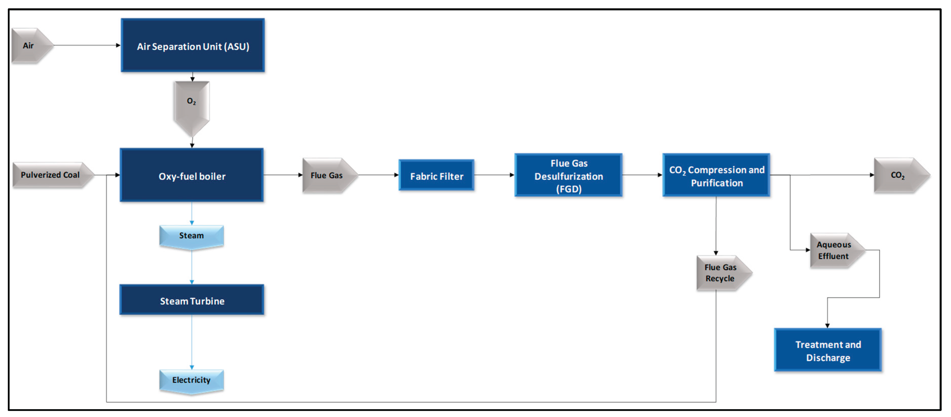
Figure 3.
Aspen Plus process flow diagram for the alkaline water electrolysis unit (NEL A3880 model).
Figure 3.
Aspen Plus process flow diagram for the alkaline water electrolysis unit (NEL A3880 model).
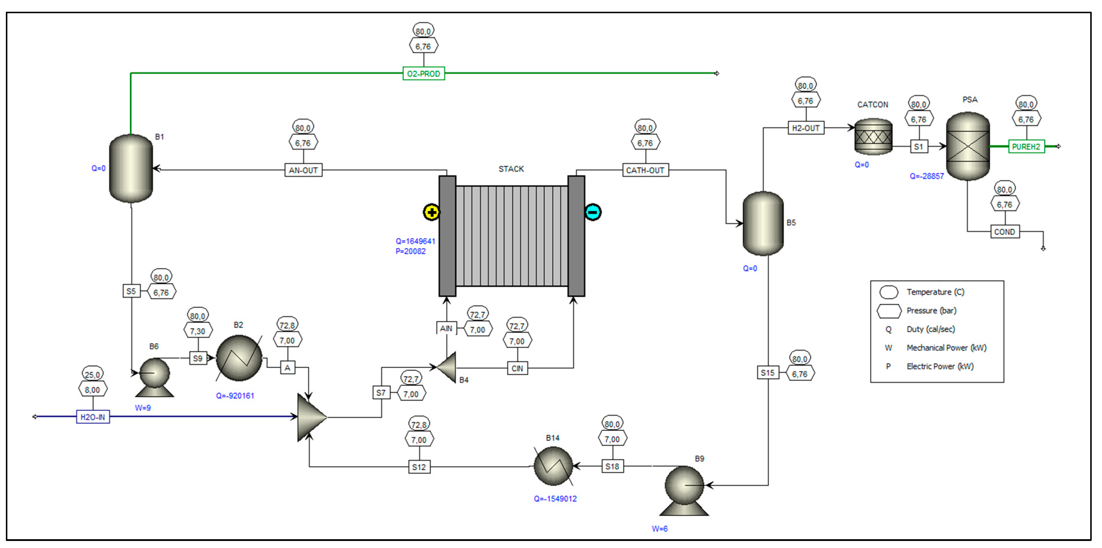
Figure 4.
Flow diagram of the methanol synthesis unit in Aspen Plus, considering process scale adjustments, reactor configuration, and inlet conditions of the H₂ and CO₂ streams.
Figure 4.
Flow diagram of the methanol synthesis unit in Aspen Plus, considering process scale adjustments, reactor configuration, and inlet conditions of the H₂ and CO₂ streams.
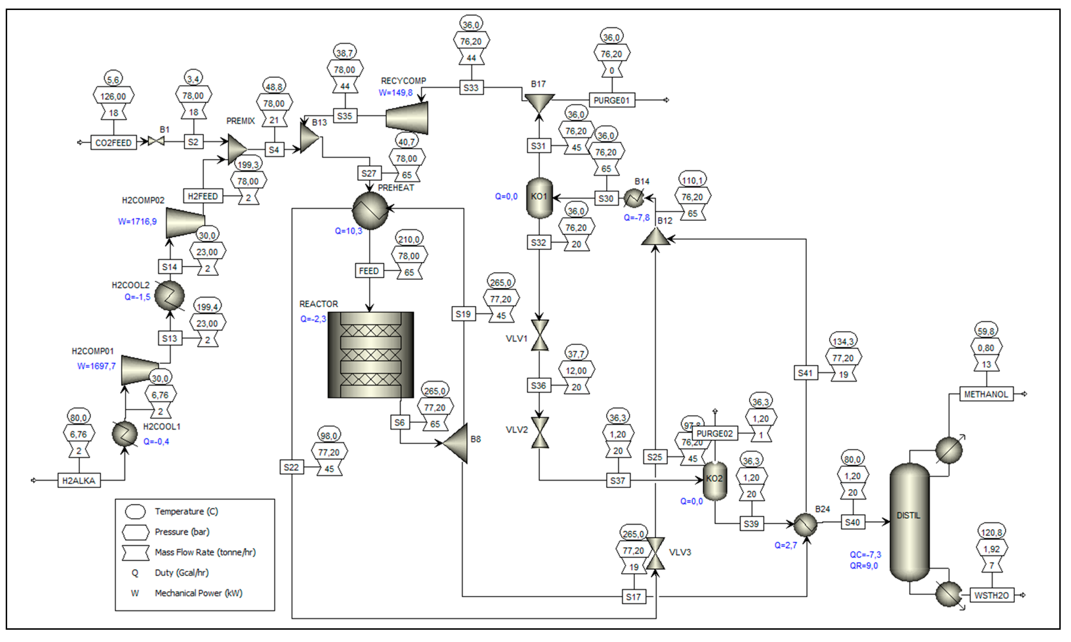
Figure 5.
Integration of results for the power-to-liquid route – main process flows.
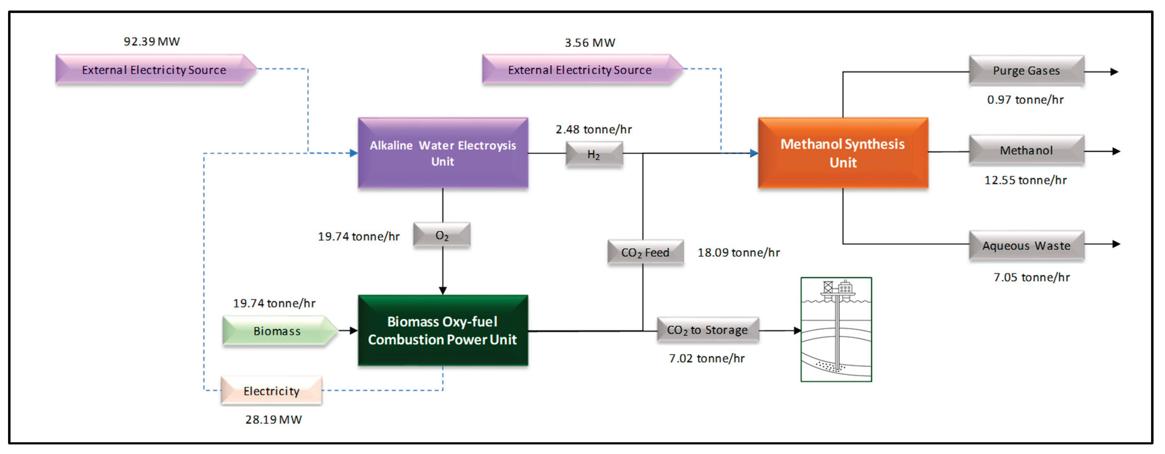

Table 1.
Proximate and ultimate analyses and calorific values of eucalyptus charcoal (dry basis).
| Main biomass properties | Unit | Value (dry basis) |
Value (as received) 1 |
|---|---|---|---|
| Proximate analysis | |||
| Ash content | wt% | 10.45 | 9.93 |
| Volatile matter | wt% | 19.22 | 18.26 |
| Fixed carbon | wt% | 70.33 | 66.81 |
| Ultimate analysis (macroelements) | |||
| Carbon | wt% | 76.1 | 72.29 |
| Hydrogen | wt% | 1.33 | 1.26 |
| Oxygen | wt% | 11.1 | 10.54 |
| Nitrogen | wt% | 1.02 | 0.97 |
| Total (with halides) | wt% | 100 | 95 |
| Heating value | |||
| Net calorific value (LHV) | MJ/kg | 27.31 | 25.94 |
| Gross calorific value (HHV) | MJ/kg | 27.6 | 26.22 |
| HHV (Milne method) | MJ/kg | 26.11 | 24.8 |
1 Values converted from the original data in the Phyllis2 database, provided on a dry basis, considering a moisture content of 5 wt%. The term as received here refers to the reference basis in which the fuel properties are determined under the conditions in which the sample is received, without a prior drying step, and does not refer to the original data provided in the Phyllis2 database.
Table 2.
Simulation of a plant specified for 100 MWg, operating in oxy-fuel combustion using the IECM tool.
Table 2.
Simulation of a plant specified for 100 MWg, operating in oxy-fuel combustion using the IECM tool.
| Parameter | Value | Unit |
|---|---|---|
| Performance | ||
| Gross Electrical Output | 100.000 | MW |
| Primary Fuel Input | 233.444 | MW |
| Net Electrical Output (MW) | 62 | MW |
| Net Plant Efficiency, HHV | 26.41% | % |
| Plant Electricity Requirements | ||
| Air Separation Use (MW) | 23.730 | MW |
| Base Plant Use (MW) | 3.303 | MW |
| In-Furnace NOx Use (MW) | 0.000 | MW |
| Fabric Filter Use (MW) | 0.053 | MW |
| Spray Dryer Use (MW) | 0.102 | MW |
| FG Recycle/Purification Use (MW) | 9.798 | MW |
| Secondary Fabric Filter Use (MW) | 0.111 | MW |
| Cooling Tower Use (MW) | 1.250 | MW |
| Major Mass Flow Rates (inputs) | ||
| Primary Fuel Input (Eucalyptus Char) | 32.060 | tonne/hr |
| Total Water Withdrawal | 232.100 | tonne/hr |
| Oxygen (O2) from ASU | 59.790 | tonne/hr |
| Major Mass Flow Rates (outputs) | ||
| Bottom Ash Disposed | 1.412 | tonne/hr |
| Fly Ash Disposed | 5.643 | tonne/hr |
| Captured CO2 | 65.670 | tonne/hr |
| Wastewater Discharge | 74.980 | tonne/hr |
| Water Evaporated (Consumptive) | 154.300 | tonne/hr |
Table 3.
Results for the scaled oxy-fuel plant using electrolytic oxygen.
| Parameter | Value | Unit |
|---|---|---|
| Performance | ||
| Gross Electrical Output | 33.012 | MW |
| Primary Fuel Input | 77.063 | MW |
| Net Electrical Output (MW) | 28.187 | MW |
| Net Plant Efficiency, HHV | 36.6% | % |
| Plant Electricity Requirements | ||
| Air Separation Use (MW) | n/a | |
| Base Plant Use (MW) | 1.090 | MW |
| In-Furnace NOx Use (MW) | 0.000 | MW |
| Fabric Filter Use (MW) | 0.018 | MW |
| Spray Dryer Use (MW) | 0.034 | MW |
| FG Recycle/Purification Use (MW) | 3.234 | MW |
| Secondary Fabric Filter Use (MW) | 0.036 | MW |
| Cooling Tower Use (MW) | 0.413 | MW |
| Major Mass Flow Rates (inputs) | ||
| Primary Fuel Input (Eucalyptus Char) | 10.584 | tonne/hr |
| Total Water Withdrawal | 76.620 | tonne/hr |
| Oxygen (O2) from ASU | 19.738 | tonne/hr |
| Major Mass Flow Rates (outputs) | ||
| Bottom Ash Disposed | 0.289 | tonne/hr |
| Fly Ash Disposed | 1.155 | tonne/hr |
| Captured CO2 | 25.112 | tonne/hr |
| Wastewater Discharge | 25.086 | tonne/hr |
| Water Evaporated (Consumptive) | 51.465 | tonne/hr |
Table 4.
Mass and Enthalpy Balance of the Alkaline Electrolysis Unit (Main Results).
| Category | Stream | Description | Property | Result | Unit |
|---|---|---|---|---|---|
| Output | PUREH2 | Specified Hydrogen Product Stream from Electrolysis | Enthalpy Flow | 0.55 | MW |
| Mass Flow | 2.48 | tonne/hr | |||
| Temperature | 80.00 | °C | |||
| Pressure | 6.76 | bar | |||
| O2-PROD | High Purity Oxygen Product Stream (97 % wt) |
Enthalpy Flow | -2.02 | MW | |
| Mass Flow | 20.36 | tonne/hr | |||
| Temperature | 80.00 | °C | |||
| Pressure | 6.76 | bar | |||
| COND | Condensed Water of PSA Block | Enthalpy Flow | -4.91 | MW | |
| Mass Flow | 1.13 | tonne/hr | |||
| Temperature | 80.00 | °C | |||
| Pressure | 6.76 | bar | |||
| Input | H2O-IN | Specified Water for Electrolysis | Enthalpy Flow | -105.65 | MW |
| Mass Flow | 23.97 | tonne/hr | |||
| Temperature | 25.00 | °C | |||
| Pressure | 8.00 | bar | |||
| Mass Balance | |||||
| Input Mass Flow | 23.97 | tonne/hr | |||
| Output Mass Flow | 23.97 | tonne/hr | |||
| Enthalpy Balance | 99.27 | MW | |||
Table 5.
Energy Inputs and Outputs for the Modular Alkaline Electrolysis Unit.
| Operation Block (as in the ASPEN PFD) |
Equipment | Network Required (6x) | Heat Duty (6x) | Unit |
|---|---|---|---|---|
| STACK | Electrolyzer | 120.49 | 41.44 | MW |
| B6 | Pump | 0.05 | 0.00 | MW |
| B2 | Heat Exchanger | 0.00 | -23.12 | MW |
| B14 | Heat Exchanger | 0.00 | -38.91 | MW |
| B9 | Pump | 0.04 | 0.00 | MW |
| PSA | Pressure Swing Adsorption |
0.00 | -0.72 | MW |
| TOTAL | 120,58 | -21.31 | MW | |
Table 6.
Mass and Enthalpy Balance of the Methanol Synthesis Unit (Main Results).
| Category | Stream | Description | Property | Result | Unit |
|---|---|---|---|---|---|
| Output | METHANOL | Top fraction of the distillation column. with a purity of 99.12 wt%. | Enthalpy Flow | -21.79 | MW |
| Mass Flow | 12.55 | tonne/hr | |||
| Temperature | 59.77 | °C | |||
| Pressure | 0.80 | bar | |||
| WSTH2O | Aqueous residue from the bottom of the distillation column | Enthalpy Flow | -30.50 | MW | |
| Mass Flow | 7.05 | tonne/hr | |||
| Temperature | 120.79 | °C | |||
| Pressure | 1.92 | bar | |||
| PURGE01 | Purge before RECYCOMP block | Enthalpy Flow | -0.76 | MW | |
| Mass Flow | 0.45 | tonne/hr | |||
| Temperature | 36.00 | °C | |||
| Pressure | 76.20 | bar | |||
| PURGE02 | Purge before DISTIL Block | Enthalpy Flow | -1.26 | MW | |
| Mass Flow | 0.52 | tonne/hr | |||
| Temperature | 36.27 | °C | |||
| Pressure | 1.20 | bar | |||
| Input | CO2FEED | CO2 captured from oxyfuel unit | Enthalpy Flow | -46.44 | MW |
| Mass Flow | 18.09 | tonne/hr | |||
| Temperature | 5.60 | °C | |||
| Pressure | 126.00 | bar | |||
| H2O-IN | Specified Water for Electrolysis | Enthalpy Flow | 0.55 | MW | |
| Mass Flow | 2.48 | tonne/hr | |||
| Temperature | 80.00 | °C | |||
| Pressure | 6.76 | bar | |||
| Mass Balance | |||||
| Input Mass Flow | 20.58 | tonne/hr | |||
| Output Mass Flow | 20.58 | tonne/hr | |||
| Enthalpy Balance | -8.42 | MW | |||
Table 7.
Energy Inputs and Outputs for the Methanol Synthesis Unit1.
| Operation Block (as in the ASPEN PFD) | Equipment | Network Required | Heat Duty | Unit | |
|---|---|---|---|---|---|
| H2COMP01 | Compressor (ηs=0.75) | 1.70 | 0 | MW | |
| H2COMP02 | Compressor (ηs=0.75) | 1.72 | 0 | MW | |
| RECYCOMP | Compressor (ηs=0.75) | 0.15 | 0 | MW | |
| H2COOL1 | Heat Exchanger | 0 | -0.50 | MW | |
| H2COOL2 | Heat Exchanger | 0 | -1.69 | MW | |
| B14 | Heat Exchanger | 0 | -9.10 | MW | |
| REACTOR | Multitube reactor (constant thermal fluid temperature) |
0 | -2.69 | MW | |
| CONDENSER (DISTIL) | Condenser | 0 | -8.49 | MW | |
| REBOILER (DISTIL) | Reboiler | 0 | 10.49 | MW | |
| TOTAL | 3.56 | -11.98 | MW | ||
1 Both PREHEAT and B24 blocks are configured as counter-current heat exchangers that exchange heat internally between process streams. Therefore, their respective heat duties are not included in the energy balance calculation for the control volume representing the methanol synthesis unit.
Disclaimer/Publisher’s Note: The statements, opinions and data contained in all publications are solely those of the individual author(s) and contributor(s) and not of MDPI and/or the editor(s). MDPI and/or the editor(s) disclaim responsibility for any injury to people or property resulting from any ideas, methods, instructions or products referred to in the content. |
© 2025 by the authors. Licensee MDPI, Basel, Switzerland. This article is an open access article distributed under the terms and conditions of the Creative Commons Attribution (CC BY) license (http://creativecommons.org/licenses/by/4.0/).
Copyright: This open access article is published under a Creative Commons CC BY 4.0 license, which permit the free download, distribution, and reuse, provided that the author and preprint are cited in any reuse.


