
Submitted:
08 July 2025
Posted:
10 July 2025
You are already at the latest version
Abstract
The paper investigates the potential of co-electrolysis as a viable pathway for hydrogen production and industrial decarbonization, expanding on previous studies on water electrolysis. The analysis adopts a general and critical perspective, aiming to assess the realistic scope of this technology in light of current energy and environmental needs. Although co-electrolysis theoretically offers improved efficiency by simultaneously converting H₂O and CO₂ into syngas, the practical advantages are difficult to consolidate. The study highlights that the energetic margins of the process remain relatively narrow, and that several key aspects, including system irreversibilities and the limited availability of CO₂ in many contexts, significantly constrain its applicability. Despite the growing interest and promising technological developments, co-electrolysis still faces substantial challenges before it can be implemented on a scale. The findings suggest that its success will depend on targeted integration strategies, advanced thermal management, and favorable boundary conditions rather than on the intrinsic efficiency of the process alone. However, there are specific sectors where assessing the implementation potential of co-electrolysis could be of interest, a perspective this paper aims to explore.
Keywords:
co-electrolysis
; carbon dioxide (CO₂) capture
; hydrogen production
; energy efficiency
; hard-to-abate industries
1. Introduction: Contextualizing Hydrogen and Co-Electrolysis
The urgent drive for decarbonization has positioned it at the core of global energy policies. Although closely linked to the broader issue of climate change, it also serves as a catalyst for innovation in the energy sector, encouraging the adoption of low-carbon technologies and the transition toward sustainable energy systems, [1]. In this context, reducing carbon dioxide emissions from industrial sectors, especially those classified as "hard-to-abate" such as steel, cement, and chemicals, is a relevant issue, [2]. Despite renewable energy sources like solar and wind power have made significant strides in decarbonizing the electricity sector, industrial processes remain heavily reliant on fossil fuels.
To reduce emissions in these energy-intensive industries, technologies such as carbon capture, utilization, and storage (CCUS), direct electrification, and hydrogen-based solutions have emerged as key strategies. Hydrogen has gained global recognition as a crucial enabler of decarbonization, providing a pathway to replace fossil fuels in sectors where direct electrification is impractical, [3]. Its versatility allows it to be used as a fuel, chemical feedstock, and energy storage medium. Low-carbon hydrogen can be produced either through Steam Methane Reforming (SMR) coupled with CCUS, known as blue hydrogen, or via water electrolysis powered by renewable energy, referred to as green hydrogen. CCUS encompasses CO₂ capture from sources such as power plants or directly from air, transportation mainly via pipelines, underground storage in geological formations, or reuse in industrial processes, which helps close the carbon loop and supports emission reduction goals. Hydrogen and CCUS are often promoted separately across industries, with hydrogen for decarbonizing fuels and CCUS for reducing industrial emissions. As green hydrogen production scales up, attention is turning to technologies that enhance overall efficiency and possibly integrate carbon reuse directly into the production process. Although blue hydrogen integrates hydrogen production with CCUS, its adoption is limited by technical and infrastructural challenges as well as environmental concerns from a life cycle perspective, [4,5]. By contrast, co-electrolysis offers a unified solution that uses renewable electricity to simultaneously convert water and CO₂ into synthetic fuels or feedstocks, providing a dual benefit of emission reduction and resource valorization, [6]. While still emerging, it can potentially overcome the limits of blue hydrogen and fragmented decarbonization strategies.
Compared to conventional electrolysis, co-electrolysis offers several advantages. The first is the possible integration of CO₂ capture and conversion: instead of merely capturing CO₂ for storage, co-electrolysis transforms it into usable energy carriers, [7]. The second is a potential higher system efficiency: the process utilizes high-temperature solid oxide electrolysis cells (SOECs), which enable better conversion efficiencies than low-temperature electrolysis, [8,9]. Challenges such as scaling up technology, ensuring economic viability, and managing system durability remain, but overall co-electrolysis presents a comprehensive pathway for industries aiming to reduce their carbon footprint.
This article explores the potential of co-electrolysis in decarbonizing hard-to-abate sectors by integrating CO₂ utilization with hydrogen production. Despite existing technological and economic hurdles, co-electrolysis could offer a sustainable alternative to conventional fossil-based processes. The co-electrolysis research reflects a complexity of approaches, primarily divided between two major lines. On one side, there are studies with a strong electrochemical focus, aiming to optimize and understand the underlying technology in detail. On the other, much of the recent attention has concentrated on high-temperature co-electrolysis, driven by its appealing characteristics, such as near-100% electricity-to-syngas efficiency and fast reaction kinetics. While justified by the integration potential with catalytic fuel synthesis and syngas production, this focus may have inadvertently overshadowed the possibilities offered by low-temperature systems. As emphasized in recent reviews, [8,9], the dominance of high-temperature approaches risks underestimating the advantages of low-temperature electrolysis, such as system modularity, operational flexibility, and potentially lower material constraints. A more balanced and integrated perspective could foster innovation across a broader technological spectrum, unlocking new opportunities for co-electrolysis development. Building on previous work by one of the authors on water electrolysis, [10], this paper examines the progress of co-electrolysis processes for hydrogen production and industrial decarbonization. The aim is to assess the viability of this technology to face current energy and environmental needs. Particular attention is given to the enabling conditions for the practical implementation of co-electrolysis, considering that CO₂ availability is often limited to specific contexts. Section 2 overviews process fundamentals and provides a comprehensive energy analysis. Section 3 outlines recent and potential technological developments, while Section 4 highlights potential applications in selected industrial settings where, despite current technical challenges and energy balance issues, co-electrolysis could hold promise, particularly in contexts where CO₂ is already available in a separated form. The aim is to shed light on sectors where implementation may be worthy of further investigation.
2. Fundamentals and Energy Analysis of Co-Electrolysis of H2O and CO2
Co-electrolysis is an advanced electrochemical process that converts water (H₂O) and carbon dioxide (CO₂) into syngas, a mixture of hydrogen (H₂) and carbon monoxide (CO). Conceptually, co-electrolysis appears highly attractive, as it embodies the principle illustrated in Figure 1: a process enabling CO₂ reduction and clean energy carriers’ production.
For this technology to be considered a viable solution, feasibility must be assessed from multiple perspectives. From an energy standpoint, process efficiency depends on operating conditions, particularly temperature, and integration with renewable sources, [11]. In addition to these factors, technical aspects such as the durability and performance of electrolyzers must be carefully evaluated alongside economic factors, including capital and operational costs, to determine the practical viability and potential of co-electrolysis. A comprehensive analysis must consider the entire transformation chain. Since CO₂ is often mixed with other gases, and syngas is a mixture of CO and H₂, separation and purification steps are required before downstream fuel synthesis.
2.1. Operating Principles of Co-Electrolysis
Considering the case illustrated in Figure 1, the electro-reduction reactions at the cathode side are:
H2O + 2e− → H2 + ½ O2−
CO2 + 2e− → CO + O2−
while the corresponding electro-oxidation reaction at the anode side is:
O2− → ½ O₂ + 2e−
Dissociation of H2O, CO2 or mixtures requires a well-defined energy input, at least equal to the standard reaction enthalpy at ambient temperature:
H2O → H2 + ½ O2 ∆H = 286 kJ/mol (at T = 25 °C)
CO2 → CO + ½ O2 ∆H = 283 kJ/mol (at T = 25 °C)
Considering the simultaneous availability of the two substances, the basic reaction is the following one:
CO2 + H2O + electricity + heat → CO + H2 + O2
Both electrical energy and heat are required to drive these dissociation reactions, with their relative contributions depending on operating temperature, as illustrated in Figure 2. The total energy required for co-electrolysis (of H₂O and CO₂) remains constant with temperature; however, as temperature increases, there is a significant shift in the distribution between the different forms of energy supplied. The portion of energy required in the form of electrical input decreases, while the thermal energy contribution increases. This behavior is linked to the temperature dependence of the Gibbs free energy, which leads to a reduction in the theoretical cell voltage (Nernst potential) at higher temperatures.
The minimum total energy requirement corresponds to the reaction enthalpy (ΔH), with the electrical energy input related to the Gibbs free energy (ΔG) and the remining part provided as thermal energy (TΔS). As can be seen, water electrolysis presents a jump in the total and thermal energy requirements due to the supply of water in the gaseous form for temperatures above the boiling point (100 °C, 1 bar). At around 825 °C the Gibbs free energy for CO₂ electrolysis becomes lower than that for H₂O electrolysis, making CO₂ reduction thermodynamically more favorable at higher temperatures.
The co-electrolysis process typically utilizes solid oxide electrolysis cells (SOECs), which operate at temperatures between 700-1000 °C, enabling higher efficiency and lower electricity consumption compared to low-temperature electrolysis. SOECs have demonstrated efficiency advantages over proton exchange membrane (PEM) and alkaline electrolysis technologies due to their ability to directly utilize thermal energy, [12]. The high-temperature environment facilitates the simultaneous reduction of H₂O and CO₂, producing H₂ and CO at the cathode while oxygen is released at the anode. High-temperature co-electrolysis reduces electrical energy demand by lowering the required electrochemical potential, as Gibbs free energy decreases with temperature, [13]. Co-electrolysis shifts a portion of the energy input from electricity to heat, which is easier and cheaper to supply. The significant thermal input required adds complexity, cost, and scalability challenges. Material stability and thermal integration are also critical issues in industrial applications, [14]. Electrodes and electrolytes must withstand high thermal and chemical stress, requiring advanced materials resistant to degradation over long operational periods. Moreover, the high-temperature operation requires robust insulation and precise thermal control to minimize heat loss and maximize efficiency, [15]. Large-scale deployment remains a challenge due to the high initial capital costs and the need for robust engineering solutions to maintain efficiency over extended use.
2.2. Energy Analysis of Co-Electrolysis
Co-electrolysis simultaneously produces H₂ and CO, with a total energy demand (electricity + heat) like that of water electrolysis. Obviously, if you consider only the energy required to produce pure hydrogen, co-electrolysis becomes less advantageous, because part of the energy is used to produce CO. In practice, co-electrolysis could be beneficial if syngas production is considered. The power required for the co-electrolysis process can be estimated by evaluating the minimum electrical potential and the number of electrons involved in the reaction. The overall electrochemical conversion of one mole of CO₂ and one mole of H₂O into CO and H₂ requires the transfer of 4 moles of electrons. In standard conditions, the theoretical minimum potential for the co-electrolysis of CO₂ and H₂O is approximately 1.46 V, which is slightly higher than that of water electrolysis alone (1.23 V). Considering a unit CO2 feed of 1 kg/s and the corresponding moles listed in Table 1, the theoretical power required to conduct the process is illustrated in Table 2.
Under real operating conditions, both the required voltage and current will be higher, leading to increased energy consumption and, consequently, higher operational costs. The required potential applied to the cell can be expressed as
V = E + ηact,a + ηact,c + ηohmic + ηconc,a + ηconc,c
where ηact,a and ηact,c are the activation overpotential at the anode and cathode, ηohmic is the ohmic overpotential, ηconc,a and ηconc,c is the concentration overpotential at the anode and cathode that contribute to increase the required power and energy used in the process. As suggested for water electrolysis by Min et al. in [15], the proper characterization of the energy performance of co-electrolysis requires clear and standardized definitions including metrics at different boundaries of the system such as efficiency and specific energy consumption. Some expressions are provided below for system efficiency for hydrogen production ηH2,syst, system efficiency for syngas production ηsyn,syst, and system specific energy consumption for hydrogen production SECH2,syst, and system specific energy consumption for syngas production, SECsyn,syst:
ηH2,syst = mH2LHVH2 / (Ẇ stack / ηAC,DC + Σ Ẇ BoP + Σ Q̇ ext)
ηsyn,syst = (ṁH2LHVH2 + ṁCOLHVCO) / (Ẇ stack / ηAC,DC + Σ Ẇ BoP + Σ Q̇ ext)
SECH2,syst = (Ẇ stack / ηAC,DC + Σ Ẇ BoP + Σ Q̇ ext) / ṁH2
SECsyn,syst = (Ẇ stack / ηAC,DC + Σ Ẇ BoP + Σ Q̇ ext) / ṁsyn
where ṁ represent the flow rates of products, Ẇ the electrical power for the cell and the auxiliary system, and Q̇ thermal power from external sources. A comparative overview is provided between conventional water electrolysis and the co-electrolysis of CO₂ and H₂O in Table 3. The comparison is based on producing 1 kg of hydrogen and includes key technical and energetic parameters such as feedstock requirements, energy consumption, operating conditions, and overall process efficiency. The values reported in Table 3 refer to highly general conditions, meant to provide a simplified and idealized benchmark. In practice, these figures can vary significantly depending on the specific configuration and integration of the system.
Table 4 reports some energy balances calculated assuming an ideally stoichiometric co-electrolysis reaction, based on a reference CO₂ feed flow rate of 1 kg/s and some hypothetical efficiencies of the whole process. Considering a higher level of 70% or a more cautionary level of 30%, we can obtain the balances, reported in Table 4 which is usually between 30% and 70% for co-electrolysis, as also discussed in [16].
The apparent energy advantage in co-electrolysis comes from the energy potential of the products, primarily hydrogen (H₂), which has a high calorific value (120 MJ/kg), and carbon monoxide (CO), which, while having a lower calorific value, still has useful industrial applications. The previously shown balances demonstrate some potential advantages of co-electrolysis from a theoretical perspective. However, the advantages of this process can only be significant if system efficiency exceeds at least 50% and if both hydrogen and carbon monoxide can be effectively valorized. By leveraging high-temperature heat, co-electrolysis can consume an energy amount well over those for simple electrolysis per kilogram of hydrogen under ideal conditions. Evaluating the efficiency of an electrolysis process, and by extension that of co-electrolysis, is challenging due to the difficulty in accounting for the various thermochemical irreversibilities involved in real systems. Table 5 shows some estimated projections of the process efficiency with respect to temperature. If co-electrolysis is to be considered for applications of meaningful scale, it would necessarily involve significant power input and substantial energy demands.
3. Outlook and Recent Developments of Co-Electrolysis of H2O and CO2
Solid Oxide Electrolysis Cells (SOECs) have emerged as a key technology for converting renewable electricity into syngas (H₂ + CO) through the high-temperature co-electrolysis of CO₂ and H₂O. Early research, such as that conducted by Ebbesen et al. in [17], investigated the feasibility and reaction mechanisms of syngas production and assessed the impact of co-electrolysis on stack degradation. Indeed, although cathode reactions are widely accepted, the detailed dissociation processes for co-electrolysis remains partly. [18]. While steam is the primary reactant in electrolysis CO2 reduction is governed by thermochemical reactions, [19].
More recent efforts have focused on improving catalyst composition to enhance electrochemical activity, efficiency, and stability. Experimental efforts have scaled SOEC technology to pilot and industrial levels (at the moment the level of 10 kW high-temperature co-electrolysis system, achieving syngas production rate of 3.08 Nm³/h and adjustable H₂/CO ratio between 1.3 and 4.8 and some possible applications in steel blast furnaces, using a steam + CO₂ mixture to produce renewable syngas, demonstrating the potential to replace natural gas in steel production. The studies on co-electrolysis and the development of early-stage experimental systems appear to be entirely focused on high-temperature systems. Table 6 highlights the reasons why high-temperature operation is preferred for co-electrolysis. This is correct from an electrochemical perspective, as it aligns with the goal of optimizing efficiency. However, it may have come at the expense of low-temperature electrolysis, which offers distinct benefits such as simpler design, lower material constraints, and easier coupling with intermittent renewable sources like photovoltaics.
In the field of co-electrolysis, achieving significant efficiency improvements requires advancements both in membrane development and in electrode material optimization. In this context, there is promising research activity, particularly focused on materials, which shows encouraging potential for further enhancement. Deka et al. in [20] studied a-site deficient perovskite oxide La₀.₇Sr₀.₂FeO₃ as a cathode material, showing that iron site doping with Ni or a combination of Ni and Co significantly improved performance. The doped cathode achieved a Faradaic efficiency of up to 100%, demonstrating excellent electrocatalytic properties. Bian et al. in [21] developed a cathode material based on pre-reduced La₀.₇Sr₀.₃Fe₀.₉Ni₀.₁O₃-δ (LSFNi), triggering the formation of uniformly distributed Ni-Fe alloy nanoparticles (~45 nm). Their system achieved current density of ~1.0 A/cm² at 1.5 V and 750°C, current density of ~2.4 A/cm² at 850°C, and Faradaic efficiency close to 100%. Bimpiri et al. in [22] observed that varying the H2O/CO2 ratio can increase the H2/CO ratio although the overall electrochemical performance of the cell remains unaffected. Moreover, SOEC co-electrolysis provides significant flexibility in syngas production, allowing for the precise control of the H₂/CO ratio, which is essential for fuel synthesis. Modifying the operating parameters the H₂/CO ratio can be adjusted from ~0.1 to ~7, leveraging the fact that H2O electrolysis dominates at low currents whereas CO2 electrolysis dominates at large currents, [23]. In a recent work, [24], Liang et al. reviewed tests of co-electrolysis and corresponding mechanisms, and durability tests under varying cell configuration and operating conditions. Stable operation for over 100 hours without carbon deposit have been demonstrated for operation with flue gases, [25]. The harsh operating conditions in co-electrolysis, particularly the need for elevated temperatures (typically between 500–800°C) to facilitate the reaction, demand specialized materials. Current materials used in solid oxide electrolysis cells (SOEC) are prone to degradation due to the high temperatures and reactive nature of the CO₂ feedstock. Researchers are exploring new materials that are both durable and efficient under these extreme conditions, but material limitations remain a significant barrier. Table 7 outlines from a qualitative point of view, critical aspects such as energy efficiency, material durability, system integration, and scalability, highlighting ongoing efforts to enhance the viability of co-electrolysis technology. Recent research efforts in the field of high-temperature SOECs for CO₂ and H₂O co-electrolysis have made some significant advancements even if commercial availability appears to be difficult in a limited time step. Expanding SOEC technology from laboratory-scale to full-scale industrial systems requires advancements in electrode materials, reactor design, and heat management to ensure long-term operation and minimal degradation. Considering the developments of the past 15 years, it remains challenging to envision this technology becoming a key solution for large-scale decarbonization. While SOECs offer high efficiency and potential integration with industrial processes, issues related to availability of low-grade thermal heat, technological complexity, high cost, durability, and scalability continue to limit their widespread adoption. Alternative approaches, including low-temperature co-electrolysis and hybrid electrolysis systems, may warrant further exploration to enhance the feasibility of electrolytic pathways in the decarbonization landscape. However, in a context where hydrogen is increasingly considered a key element for stabilizing energy loads in a renewable-based system, it is worth questioning whether low-temperature co-electrolysis should also be revisited. Exploring its potential in conjunction with PEM technologies, currently experiencing significant advancements in the field of electrolysis, could open new pathways for more flexible and adaptable hydrogen production solutions. A promising example of such an approach is the CO2Chem project, conducted by Sebastien et al. in [26], which focuses on the development of a polymeric electrolyte electrochemical reactor operating at low temperatures (30-95°C). The project aims to achieve a one-step conversion of CO₂ and water into methanol, utilizing surplus renewable energy. This approach could overcome some of the limitations of high-temperature SOECs by offering a lower temperature range (30-95°C), reducing material degradation and simplifying system design. While SOECs have been at the center of research due to their high efficiency and ability to operate at large scales, low-temperature co-electrolysis might offer a complementary solution.
4. Potential Application of Co-Electrolysis in Specific Industrial Contexts
Decarbonizing hard-to-abate industrial sectors is a cornerstone of modern energy policy. A major challenge for the real-world implementation of co-electrolysis is that the CO₂ produced in many industrial processes is mixed with other gases and not readily separated, posing significant barriers for its direct use. The separation of CO₂ from combustion gas streams is known to be a highly energy-intensive process, a topic that one of the authors of this work investigated extensively in earlier studies, [27]. Co-electrolysis becomes attractive primarily when CO₂ is already available in a separated or easily recoverable form, and when the system design allows for the integration of thermal energy to reduce the overall electrochemical load. In this regard, chemical and petrochemical industries offer promising scenarios, as processes like ammonia or methanol production generate relatively pure CO₂ streams that can be internally reused for further conversion. The practical implementation of co-electrolysis remains limited to contexts where CO₂ separation is intrinsic to the process, highlighting both the opportunities and the constraints of this emerging solution. In the following section, some illustrative cases will be explored where co-electrolysis may conceptually make sense, offering preliminary insights into contexts in which this technology could potentially be integrated with minimal additional energy burden.
4.1. Cement Production
The cement industry stands out as a prime example of a hard-to-abate sector—those industries where emissions are particularly difficult to reduce through electrification or energy efficiency alone. Cement production involves not only significant energy use but also process-related CO₂ emissions from the calcination of limestone. This makes the sector a critical testing ground for emerging decarbonization technologies, including the use of hydrogen as an alternative fuel and the development of carbon capture, utilization, and storage (CCUS) solutions. Hydrogen, in particular, is being explored as a viable substitute for fossil fuels in cement kilns, helping to reduce emissions while maintaining production performance. A detailed and up-to-date overview of recent developments in the sector can be found in [28,29]. The cement sector represents a more promising case for co-electrolysis too. During the calcination of limestone to produce clinkers. The cement manufacturing process begins with raw materials such as limestone (CaCO₃), clay, shale and iron ore. These materials are crushed, blended, and heated in a rotary kiln at temperatures of around 1400–1450°C. During this process, limestone decomposes into calcium oxide (CaO), which then reacts with silica (SiO₂), alumina (Al₂O₃), and iron oxides (Fe₂O₃) to form the main clinker phases as Tricalcium silicate (C₃S - Ca₃SiO₅), Dicalcium silicate (C₂S - Ca₂SiO₄), Tricalcium aluminate (C₃A - Ca₃Al₂O₆), Tetracalcium aluminoferrite (C₄AF - Ca₄Al₂Fe₂O₁₀). The resulting clinker is then additivated with other elements like gypsum (CaSO₄) to produce Portland cement, the key ingredient in concrete. Figure 3 provides a simplified schematic view of the process.
A relatively concentrated stream of CO₂ is generated in the clinker production process, limestone (CaCO₃) is heated in a kiln to produce clinker, which is the primary ingredient for cement. This process involves two key steps:
CaCO₃ (s)→CaO (s)+CO₂ (g)
(12)
- −
- Calcination of Limestone: at high temperatures (approximately 900-1000°C), limestone (CaCO₃) undergoes a chemical reaction known as calcination. During this reaction, calcium carbonate decomposes into calcium oxide (CaO), also known as lime, and carbon dioxide (CO₂):
- −
- The CaO produced is solid and remains in the kiln, while the CO₂ is released into the atmosphere as a gas.
- −
- Clinker Formation: the CaO produced in the calcination step then reacts with other materials in the kiln, such as silica (SiO₂), alumina (Al₂O₃), and iron oxide (Fe₂O₃), at higher temperatures (around 1400-1450°C). These reactions result in the formation of clinker, a solid material that is ground into cement.
About 68% of the total CO₂ emissions from the cement production come from this calcination step. So significant amounts of CO₂ are separated during the process, making these facilities potential candidates for integrating co-electrolysis.
To get an idea of the amount of CO2 available, consider a medium to large-scale plant producing 1 million tons per year. This highlights how interesting it could be to implement co-electrolysis with the goal of reducing CO2 emissions. Table 8 provides some relevant data on CO₂ emissions from such a plant. This could also be a sector where co-electrolysis—with the simultaneous electrochemical conversion of CO₂ and H₂O into syngas, shows interesting potential. An analysis of the dimensional data also highlight the importance of scale: any meaningful application would require systems of significant size and power capacity.
4.2. Natural Gas and Biogas Processing Facilities
A field in which co-electrolysis could have interesting developments is natural gas refineries. In these facilities, the separation of CO₂ from the gas is often mandatory and can be carried out using different methods, including sorbents, membranes, or cryogenic techniques. In these plants, raw natural gas contains significant amounts of acid gases, including CO₂, that must be removed to meet pipeline quality specifications. This separation is typically achieved using technologies such as amine scrubbing, which yields a high-purity CO₂ stream as a byproduct. Gas separation membranes (Figure 4) are particularly interesting due to their simplicity of use. However, they do not guarantee a high-purity CO₂ stream in a single step, so solvent-assisted membranes are being developed, combining the advantages of membranes with those of chemical absorption.
This separated CO₂ is produced in large volumes and, rather than being vented or used solely for enhanced oil recovery, it could serve as an ideal feedstock for co-electrolysis processes. By combining this CO₂ with water, the co-electrolysis process can convert these inputs into valuable products like hydrogen and carbon monoxide. Leveraging the already separated CO₂ from natural gas sweetening not only enhances the overall efficiency of the process but also provides a sustainable pathway for utilizing what would otherwise be considered waste. This integration could be particularly beneficial in regions with extensive natural gas processing infrastructure, offering a pathway for decarbonizing sectors by coupling with renewable energy sources to drive the co-electrolysis reaction. Various literature sources report that the CO₂ content in natural gas can vary significantly depending on the source and processing. For instance, pipeline-quality natural gas is typically treated to reduce CO₂ levels to less than 2%. However, raw natural gas from sour fields can contain much higher concentrations of CO₂. Studies indicate that in many sour gas reservoirs, the CO₂ content can range from 5% up to 15%, and in some extreme cases even exceed 20%. For example, the U.S. Department of Energy (DOE) has noted that raw natural gas may include CO₂ in the range of 2–15% by volume, depending on the field characteristics. Additionally, Bahadori in [30] reported that sour gas fields often exhibit CO₂ concentrations on the order of 15% or more, whereas the gas destined for distribution is typically treated to contain only trace amounts of CO₂. These figures suggest that natural gas processing facilities, particularly those handling sour gas, can yield significant streams of relatively pure CO₂ through separation processes like amine scrubbing. Such streams could potentially serve as an attractive feedstock for co-electrolysis processes, converting CO₂ into valuable chemicals when integrated with renewable energy sources. The fermentation of corn is a well-established industrial process primarily used to produce bioethanol; a renewable fuel widely utilized in the transportation sector. Another relevant case is that of biogas produced from anaerobic digestion processes, which are widely implemented and could be effectively integrated into co-electrolysis-schemes to produce synthetic fuels. This pathway offers a promising opportunity to combine renewable electricity with carbon-containing feedstocks of biological origin, as in Figure 5.
4.3. Carbon Dioxide Generation and Capture in Corn Fermentation for Bioethanol Production
Another particularly interesting field for the potential application of co-electrolysis of CO₂ and H₂O is bioethanol production. This topic has been widely explored in the literature and encompasses various perspectives, as outlined in [31]. One of the key byproducts of bioethanol production is CO₂, which is generated in significant amounts during ethanol fermentation. This makes corn-based bioethanol production an interesting case for CO₂ utilization. Corn fermentation involves several stages:
- − Milling and Starch Preparation: The corn is ground to release starch, which is then broken down into fermentable sugars through enzymatic hydrolysis.
- − Liquefaction and Saccharification: Enzymes (such as amylase) convert starch into simple sugars like glucose and maltose.
- − Fermentation: Yeast: converts glucose into ethanol and CO₂:
C6H12O6 2 C2H5OH + 2 CO2
Figure 6 provides a simplified schematic diagram of the process. This process typically takes 48-72 hours and occurs at temperatures between 30-35°C. Ethanol is separated from the fermentation broth and purified to 95-99% concentration. For every ton of ethanol produced, approximately 0.8-1 ton of CO₂ is released. The CO₂ produced during fermentation is relatively pure, making it suitable for various industrial applications, including food and beverage industry (carbonation of soft drinks), agriculture (enhancing plant growth in greenhouses) but certainly fuel synthesis too (conversion of CO₂ into synthetic fuels via processes like co-electrolysis).
4.4. Co-Electrolysis of CO2 and H20 in the Power Sector: The Case of Geothermal Power Plants
While the reduction of CO₂ emissions from thermoelectric power generation is often discussed as a possibility, the application of CO₂ separation techniques remain largely impractical, as previous studies have shown them to be economically unfeasible. However, one interesting case that could be considered is geothermal power generation. It is well known that CO₂ is one of the main components of geothermal fluids.
The development of CO₂ and H₂O co-electrolysis—both abundantly present in geothermal fluids—offers an interesting opportunity to decarbonize geothermal energy production while simultaneously generating hydrogen. Examining geothermal energy production in the Monte Amiata and Larderello areas, CO₂ emissions vary between approximately 250 and 520 kg/MWh of electricity produced. While the lower end of this range may be considered acceptable, the higher value is problematic, as it even exceeds the emission levels of natural gas-fired combined cycle power plants (around 350 kg/MWh). Table 10 presents CO₂ emissions from various geothermal power plants worldwide, highlighting the significant variability influenced by geological and operational factors. These high emissions negatively impact the social acceptability of certain geothermal plants.
In geothermal power plants, particularly in regions with dominant steam production such as Larderello, CO2 is often separated from the steam. This results in significant amounts of CO2 being extracted, which is often released into the atmosphere. This CO2 could be effectively utilized for hydrogen production through the process of co-electrolysis, which combines CO2 and H2O to produce hydrogen (H2) and carbon monoxide (CO). This idea presents an intriguing opportunity for the utilization of both the CO2 and the available steam in geothermal plants. By utilizing the CO2 separated in geothermal plants, it is possible to reduce the environmental impact of these plants. Geothermal plants already provide a renewable, continuous energy source. A portion of this energy could be redirected to power the co-electrolysis process, allowing for the sustainable production of hydrogen. For illustrative purposes, some significant data from one of the plants in the Larderello area, like in Figure 7 can be reported.
The Larderello geothermal field contains superheated steam at a temperature of approximately 200°C with a CO₂ content of around 5%. This means that for every 1 kg/s of geothermal fluid, about 0.05 kg/s consists of CO₂. Therefore, to obtain a CO₂ flow rate of 1 kg/s, a geothermal fluid flow of approximately 20 kg/s would be required. The geothermal plant operates under standard inlet conditions defined by ENEL for design purposes: a pressure of 5 bar absolute, a temperature of 195°C, and a CO₂ content of approximately 5%. For a 60 MW power plant, the nominal inlet mass flow rate is set at 111.1 kg/s, serving as a reference value for plant sizing. The mixing condensers operate at pressures of 0.08 bar and 0.272 bar, ensuring a balanced compression ratio between the two compressors. The data of the plant is reported in Table 10. Although geothermal energy is a limited and, in some respects, controversial resource, the development of co-electrolysis could enable the exploitation of certain resources currently unused due to high CO₂ concentrations. This is particularly true for saturated vapor two-phase systems, where co-electrolysis could convert the abundant CO₂ and H₂O into syngas or other valuable products, thereby improving the overall system efficiency. By analyzing the data in Table 11 and taking into account the CO₂ mass flows, it is possible to estimate the power levels involved, as well as the significant amount of hydrogen that could potentially be produced in geothermal plants with dry steam source, according to Table 1.
5. Conclusions
In this paper, we have analyzed from a general point of view the co-electrolysis of CO₂ and H₂O, a process that enables the simultaneous production of hydrogen and carbon monoxide, resulting in syngas, a key feedstock for synthetic fuels and chemicals. From a thermodynamic point of view, the process appears of interest in the perspective of decarbonization. It benefits from high-temperature operation (700–900 °C), where heat replaces part of the electrical input, thus improving overall energy efficiency. However, the efficiency advantage is only meaningful if both H₂ and CO are valued outputs. If hydrogen alone is the target, the process becomes less efficient due to the energy diverted to CO₂ reduction. For syngas production, especially when using renewable electricity and waste heat, co-electrolysis offers a potentially integrated and sustainable route.
From a thermochemical perspective, co-electrolysis is limited in application and current results; in practice, achieving efficiencies above 30–40% remains challenging. The process becomes more favorable when operated at high temperatures (700–800 °C), particularly in contexts where substantial amounts of waste heat are available. Under these conditions, the energy input requirements can be partially offset, improving the overall viability of the system.
Practical implementation remains challenging. The hydrogen yield is modest, about 46 kg of H₂ per ton of CO₂, and the energy input is considerable, ranging from 10 to 15 MWh/tCO₂. Co-electrolysis can be surely considered as an interesting opportunity in sectors with readily available, concentrated CO₂ streams and decarbonization mandates, such as cement production, natural gas processing, bio-ethanol production and geothermal energy. Still, current technological complexity, sizing problems and high cost in connection with the actual limited commercial readiness, raise doubts about large-scale deployment.
Although co-electrolysis aligns conceptually with the principles of Industry 5.0—promoting sustainable, resilient, and human-centric industrial systems, its practical implementation is constrained by narrow energy margins. The high energy demand relative to the hydrogen yield limits its attractiveness, particularly when compared to alternative hydrogen production technologies.
In conclusion, while co-electrolysis of CO2 and H20 holds conceptual promise, its practical viability in industrial decarbonization hinges on overcoming technical constraints related to energy efficiency, system design, and scalability. Moreover, the significant energy demand associated with large-scale implementation raises additional concerns about the availability of sufficient renewable electricity and waste thermal heat, a key requirement if the process is to contribute meaningfully to low-carbon strategies. Its future role as either a practical solution or a persistent challenge will largely depend on progress in addressing these technical and energy-related limitations.
Data Availability Statement
The original contributions presented in the study are included in the article. Further inquiries can be directed to the corresponding author.
Conflicts of Interest
The authors declare no conflict of interest.
Abbreviations and Acronyms
The following abbreviations are used in this manuscript:
| AC | Alternate Current |
| act, a | Activation at anode |
| act, c | Activation at cathode |
| conc, a | Concentration at anode |
| conc, c | Concentration at cathode |
| DC | Direct Current |
| E | Ideal Potential [V] |
| F | Faraday's constant |
| I | Current [A] |
| LHV | Lower Heating Value [MJ/kg] |
| M | Mass flow rate [kg/s] |
| Ne | Number of “moles” of electrons |
| ohmic | Ohmic overpotential |
| P | Pressure [bar] |
| PEM | Proton Exchange Membrane |
| Q | Charge [Coulomb] |
| Q̇ | Thermal power [W] |
| SEC | Specific energy consumption [kWh/kg] |
| SOEC | Solid Oxide Electrolytic Cell |
| Syn | Syngas |
| T | Temperature |
| V | Potential [V] |
| Ẇ | Power [W] |
| X | Steam quality |
| ηact | Activation overpotential |
| h | Efficiency |
| DG | Gibbs free energy [kJ/kmol] |
| DH | Enthalpy of the reactions [kJ/kmol] |
References
- Hydrogen Council (2021). Hydrogen Council Report-Decarbonization Pathways: Hydrogen Council Report-Decarbonization Pathways Part 1: Life cycle Assessment Part 2: Supply Scenarios available. Available online: https://hydrogencouncil.com/wp-content/uploads/2021/04/Hydrogen-Council-Report_Decarbonization-Pathways_Part-1-Lifecycle-Assessment.pdf.
- Blank, T. K. , & Molly, P. (2020). Hydrogen’s decarbonization impact for industry. Near-term challenges and long-term potential. Report of the Rocky Mountain Institute. Available online: https://www.fuelcellpartnership.net/sites/default/files/Rocky_Mountain_Institute_hydrogen_insight_brief-1.pdf.
- Franco, A.; Giovannini, C. Routes for Hydrogen Introduction in the Industrial Hard-to-Abate Sectors for Promoting Energy Transition. Energies 2023, 16, 6098. [Google Scholar] [CrossRef]
- Bauer, C.; Treyer, K.; Antonini, C.; Bergerson, J.; Gazzani, M.; Gencer, E.; Gibbins, J.; Mazzotti, M.; McCoy, S.T.; McKenna, R.; et al. On the Climate Impacts of Blue Hydrogen Production. Sustain. Energy Fuels 2022, 6, 66–75. [Google Scholar] [CrossRef]
- Howarth, R.W.; Jacobson, M.Z. How Green Is Blue Hydrogen? Energy Science & Engineering 2021, 9, 1676–1687. [Google Scholar] [CrossRef]
- Boston Metal (2023). Zero CO2 Steel by Molten Oxide Electrolysis: A Path to 100% Global Steel Decarbonization. Available online: https://www.bostonmetal.com/news/zero-co2-steel-by-molten-oxide-electrolysis-a-path-to-100-global-steel-decarbonization/.
- Crownhart, C. (2022). How green steel made with electricity could clean up a dirty industry. Available online: https://www.technologyreview.com/</italic>2022/06/28/1055027/green-steel-electricity-boston-metal/.
- Graves, C.; Ebbesen, S.D.; Mogensen, M.; Lackner, K.S. Sustainable Hydrocarbon Fuels by Recycling CO 2 and H 2 O with Renewable or Nuclear Energy. Renew. Sustain. Energy Rev. 2011, 15, 1–23. [Google Scholar] [CrossRef]
- Zong, S.; Zhao, X.; Jewell, L.L.; Zhang, Y.; Liu, X. Advances and Challenges with SOEC High Temperature Co-Electrolysis of CO2/H2O: Materials Development and Technological Design. Carbon Capture Sci. Technol. 2024, 12, 100234. [Google Scholar] [CrossRef]
- Franco, A.; Giovannini, C. Recent and Future Advances in Water Electrolysis for Green Hydrogen Generation: Critical Analysis and Perspectives. Sustainability 2023, 15, 16917. [Google Scholar] [CrossRef]
- Jensen, S.H.; Larsen, P.H.; Mogensen, M. Hydrogen and Synthetic Fuel Production from Renewable Energy Sources. Inter-Natl. J. Hydrog. Energy 2007, 32, 3253–3257. [Google Scholar] [CrossRef]
- Belsa, B.; Xia, L.; García De Arquer, F.P. CO2 Electrolysis Technologies: Bridging the Gap toward Scale-up and Commercial-ization. ACS Energy Lett. 2024, 9, 4293–4305. [Google Scholar] [CrossRef]
- Xia, R.; Overa, S.; Jiao, F. Emerging Electrochemical Processes to Decarbonize the Chemical Industry. JACS Au 2022, 2, 1054–1070. [Google Scholar] [CrossRef]
- Gao, N.; Quiroz-Arita, C.; Diaz, L.A.; Lister, T.E. Intensified Co-Electrolysis Process for Syngas Production from Captured CO2. Journal of CO2 Utilization 2021, 43, 101365. [Google Scholar] [CrossRef]
- Min, G.; Choi, S.; Hong, J. A Review of Solid Oxide Steam-Electrolysis Cell Systems: Thermodynamics and Thermal Integration. Appl. Energy 2022, 328, 120145. [Google Scholar] [CrossRef]
- Kupecki, J.; Motylinski, K.; Jagielski, S.; Wierzbicki, M.; Brouwer, J.; Naumovich, Y.; Skrzypkiewicz, M. Energy Analysis of a 10 kW-Class Power-to-Gas System Based on a Solid Oxide Electrolyzer (SOE). Energy Conversion and Management 2019, 199, 111934. [Google Scholar] [CrossRef]
- Ebbesen, S.D.; Graves, C.; Mogensen, M. Production of Synthetic Fuels by Co-Electrolysis of Steam and Carbon Dioxide. -Ternational J. Green Energy 2009, 6, 646–660. [Google Scholar] [CrossRef]
- Zhang, X.; Song, Y.; Wang, G.; Bao, X. Co-Electrolysis of CO2 and H2O in High-Temperature Solid Oxide Electrolysis Cells: Recent Advance in Cathodes. J. Energy Chem. 2017, 26, 839–853. [Google Scholar] [CrossRef]
- Kim, S.-W.; Kim, H.; Yoon, K.J.; Lee, J.-H.; Kim, B.-K.; Choi, W.; Lee, J.-H.; Hong, J. Reactions and Mass Transport in High Temperature Co-Electrolysis of Steam/CO2 Mixtures for Syngas Production. J. Power Sources 2015, 280, 630–639. [Google Scholar] [CrossRef]
- Deka, D.J.; Gunduz, S.; Fitzgerald, T.; Miller, J.T.; Co, A.C.; Ozkan, U.S. Production of Syngas with Controllable H2/CO Ratio by High Temperature Co-Electrolysis of CO2 and H2O over Ni and Co- Doped Lanthanum Strontium Ferrite Perovskite Cathodes. Appl. Catal. B: Environ. 2019, 248, 487–503. [Google Scholar] [CrossRef]
- Bian, L.; Duan, C.; Wang, L.; Chen, Z.; Hou, Y.; Peng, J.; Song, X.; An, S.; O’Hayre, R. An All-Oxide Electrolysis Cells for Syngas Production with Tunable H2/CO Yield via Co-Electrolysis of H2O and CO2. Journal of Power Sources 2021, 482, 228887. [Google Scholar] [CrossRef]
- Bimpiri, N.; Konstantinidou, A.; Tsiplakides, D.; Balomenou, S.; Papazisi, K.M. Effect of Steam to Carbon Dioxide Ratio on the Performance of a Solid Oxide Cell for H2O/CO2 Co-Electrolysis. Nanomaterials 2023, 13, 299. [Google Scholar] [CrossRef]
- Cinti, G.; Discepoli, G.; Bidini, G.; Lanzini, A.; Santarelli, M. Co-Electrolysis of Water and CO2 in a Solid Oxide Electrolyzer (SOE) Stack: Study of High-Temperature Co-Electrolysis Reactions in SOEC. Int. J. Energy Res. 2016, 40, 207–215. [Google Scholar] [CrossRef]
- Liang, J.; Zhu, J.; Han, M.; Hua, X.; Li, D.; Ni, M. The Development of Solid Oxide Co-Electrolysis of H2 O and CO2 on Large-Size Cells and Stacks. iEnergy 2023, 2, 109–118. [Google Scholar] [CrossRef]
- Zheng, Y.; Zhou, J.; Zhang, L.; Liu, Q.; Pan, Z.; Chan, S.H. High-Temperature Electrolysis of Simulated Flue Gas in Solid Oxide Electrolysis Cells. Electrochim. Acta 2018, 280, 206–215. [Google Scholar] [CrossRef]
- Sebastián, D., Palella, A., Siracusano, S., Lo Vecchio, C., Monforte, G., Baglio, V., Spadaro, L., & Aricò, A. S. (2016). Development of an electrochemical co-electrolysis system for CO₂ and H₂O with a polymer electrolyte operating at low temperature for CO₂ reduction (CO2CHEM) - R.E. 45/16. CNR-ITAE. Available online: https://publications.cnr.it/doc/359565.
- Franco, A.; Diaz, A.R. Environmental Sustainability of CO2 Capture in Fossil Fuel Based Power Plants. In Proceedings of the Ecosytems and Sustainable Development VI; Vol. I; WIT Press: Coimbra, Portugal, August 17, 2007; pp. 251–261. [Google Scholar]
- Guo, Y. , Luo, L., Liu, T., Hao, L., Li, Y., Liu, P., & Zhu, T. (2024). A review of low-carbon technologies and projects for the global cement industry. Journal of Environmental Sciences, 136, 682-697.
- Volaity, S. S. , Aylas-Paredes, B. K., Han, T., Huang, J., Sridhar, S., Sant, G.,... & Neithalath, N. (2025). Towards decarbonization of cement industry: a critical review of electrification technologies for sustainable cement production. npj Materials Sustainability, 3(1), 23.
- Bahadori, A. Natural Gas Processing: Technology and Engineering Design; Elsevier: Amsterdam ; Boston, 2014; ISBN 978-0-08-099971-5.
- Joyia, M. A. K., Ahmad, M., Chen, Y. F., Mustaqeem, M., Ali, A., Abbas, A., & Gondal, M. A. (2024). Trends and advances in sustainable bioethanol production technologies from first to fourth generation: a critical review. Energy Conversion and Management, 321, 119037.
- Frondini, F.; Caliro, S.; Cardellini, C.; Chiodini, G.; Morgantini, N. Carbon Dioxide Degassing and Thermal Energy Release in the Monte Amiata Volcanic-Geothermal Area (Italy). Appl. Geochem. 2009, 24, 860–875. [Google Scholar] [CrossRef]
- Taussi, M.; Nisi, B.; Brogi, A.; Liotta, D.; Zucchi, M.; Venturi, S.; Cabassi, J.; Boschi, G.; Ciliberti, M.; Vaselli, O. Deep Regional Fluid Pathways in an Extensional Setting: The Role of Transfer Zones in the Hot and Cold Degassing Areas of the Larderello Geo-thermal System (Northern Apennines, Italy). Geochem Geophys Geosyst 2023, 24, e2022GC010838. [Google Scholar] [CrossRef]
- Fridriksson, T.; Merino, A.M.; Yasemin Orucu, A.; Audinet, P. Greenhouse Gas Emissions from Geothermal Power Production. In Proceedings of the PROCEEDINGS, 42nd Workshop on Geothermal Reservoir Engineering Stanford University; 2017. [Google Scholar]
- Ármannsson, H.; Fridriksson, T.; Wiese, F.; Hernandez, P.; Pérez, N.M. CO2 Budget of the Krafla Geothermal System, NE-Iceland. 2007. [Google Scholar] [CrossRef]
- Bloomberg, S.; Werner, C.; Rissmann, C.; Mazot, A.; Horton, T.; Gravley, D.; Kennedy, B.; Oze, C. Soil CO2 Emissions as a Proxy for Heat and Mass Flow Assessment, T Aupō V Olcanic Z One, N Ew Z Ealand. Geochem Geophys Geosyst 2014, 15, 4885–4904. [Google Scholar] [CrossRef]
- Lasco, R.D.; Lales, J.S.; Arnuevo, Ma.T.; Guillermo, I.Q.; De Jesus, A.C.; Medrano, R.; Bajar, O.F.; Mendoza, C.V. Carbon Dioxide (CO2) Storage and Sequestration of Land Cover in the Leyte Geothermal Reservation. Renew. Energy 2002, 25, 307–315. [Google Scholar] [CrossRef]
- Bettagli, N.; Bidini, G. Larderello-Farinello-Valle Secolo Geothermal Area: Exergy Analysis of the Transportation Network and of the Electric Power Plants. Geothermics 1996, 25, 3–16. [Google Scholar] [CrossRef]
Figure 1.
Conceptual representation of CO₂ and H₂O co-electrolysis.
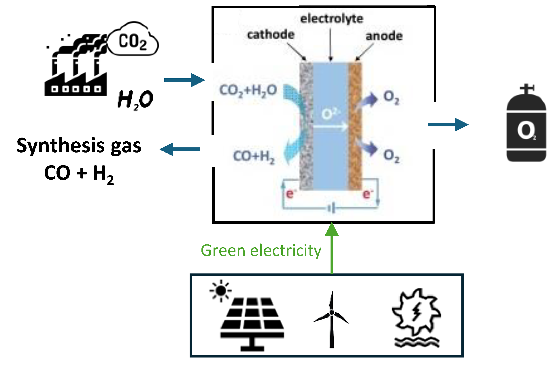
Figure 2.
Temperature variation of total, electrical, and thermal energy requirements for water and CO2 electrolysis.
Figure 2.
Temperature variation of total, electrical, and thermal energy requirements for water and CO2 electrolysis.
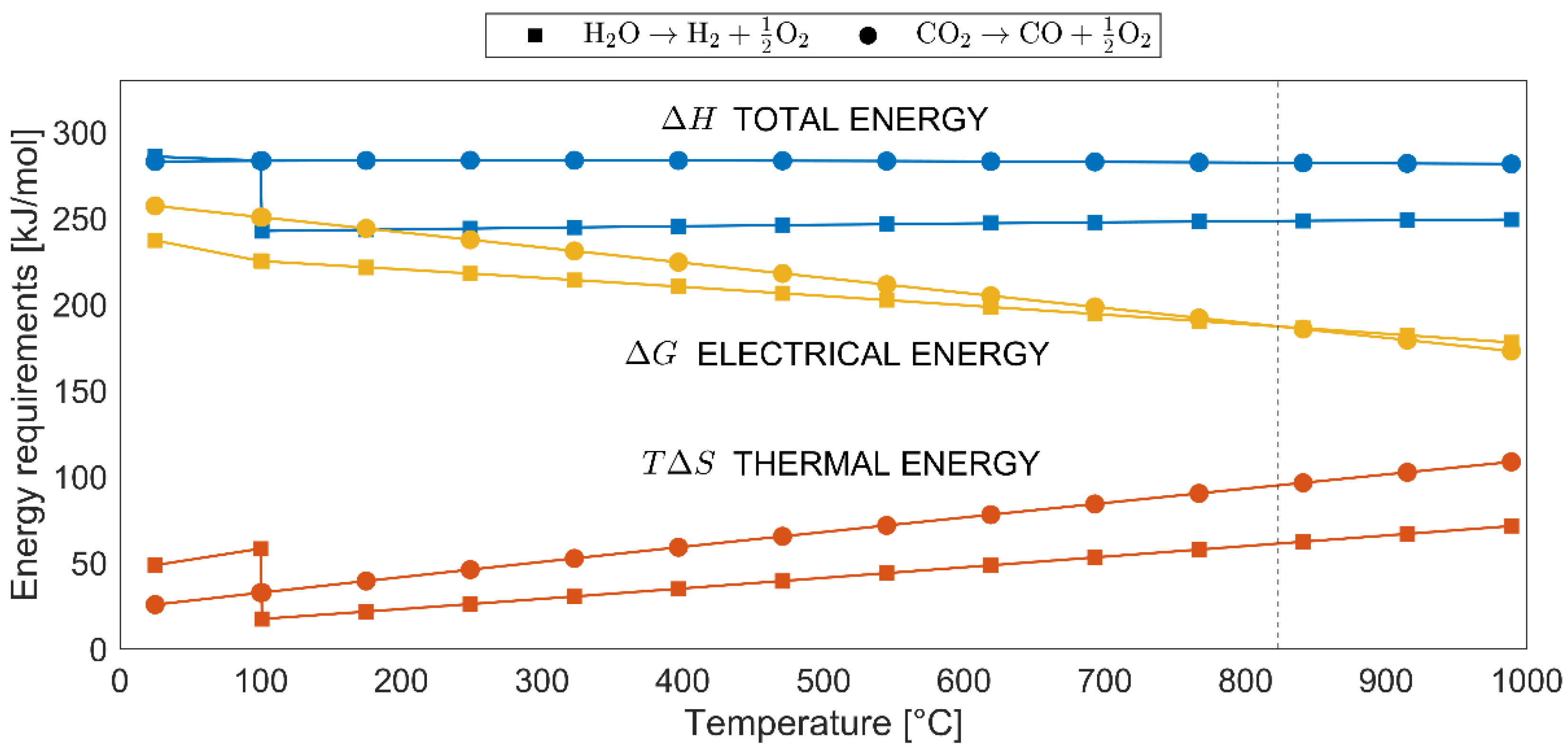
Figure 3.
Schematic representation of the cement production process, illustrating the main stages.
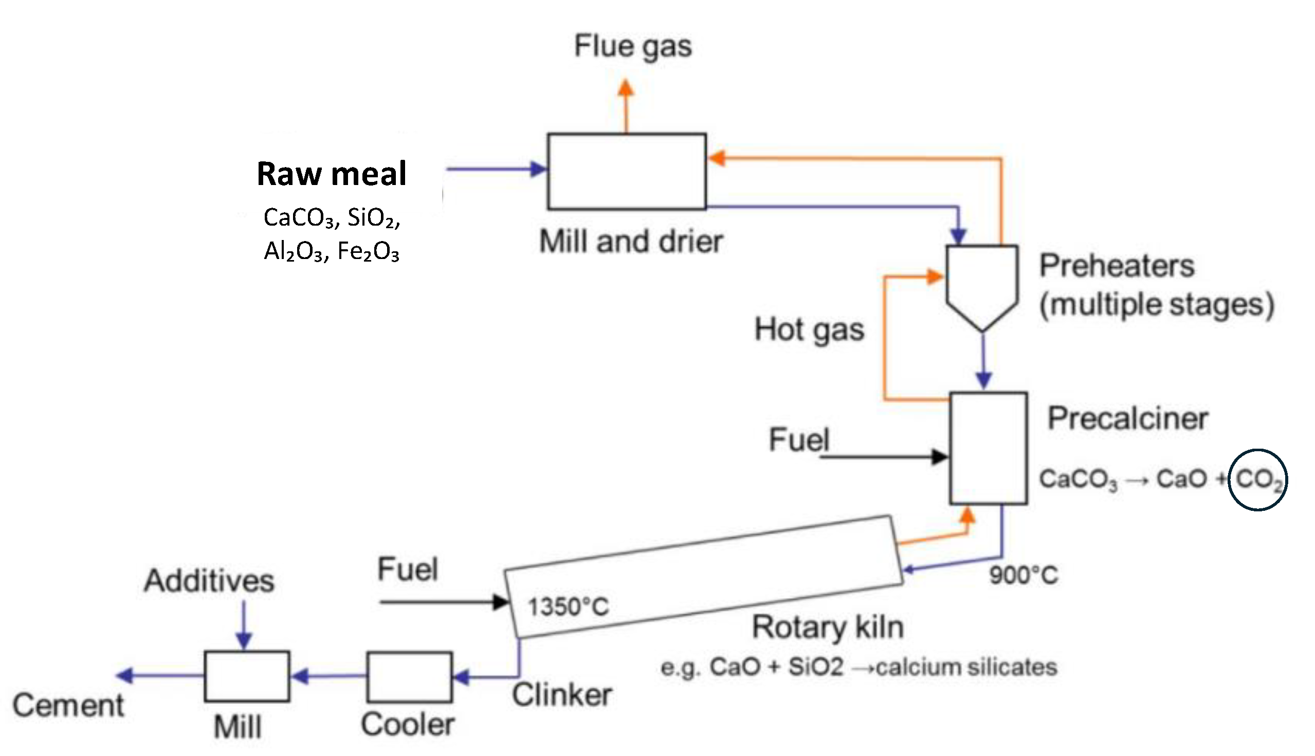
Figure 4.
Simplified schematic of CO₂ separation using membranes.
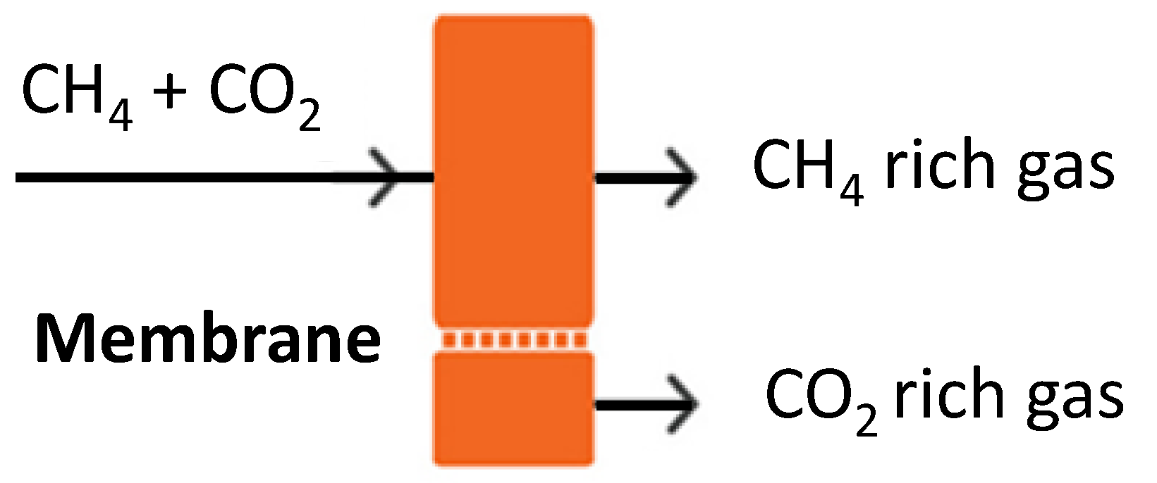
Figure 5.
Conceptual scheme of a biorefinery integrating biogas and co-electrolysis. CO₂ from anaerobic digestion is combined with H₂O in a high-temperature co-electrolysis unit powered by renewable electricity, producing syngas for synthetic fuel synthesis.
Figure 5.
Conceptual scheme of a biorefinery integrating biogas and co-electrolysis. CO₂ from anaerobic digestion is combined with H₂O in a high-temperature co-electrolysis unit powered by renewable electricity, producing syngas for synthetic fuel synthesis.
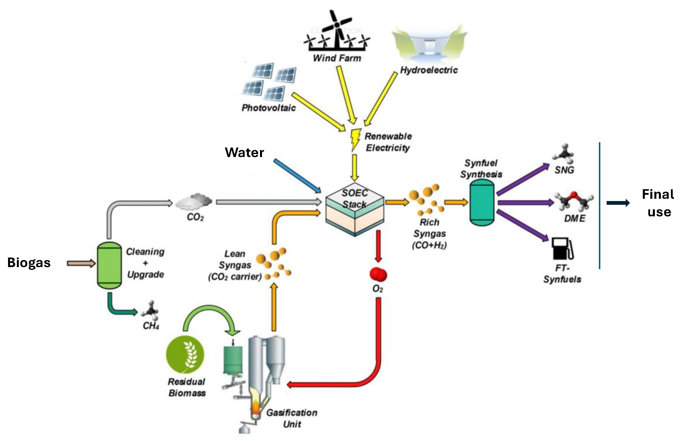
Figure 6.
Simplified diagram of the ethanol production via fermentation, with CO₂ separation.
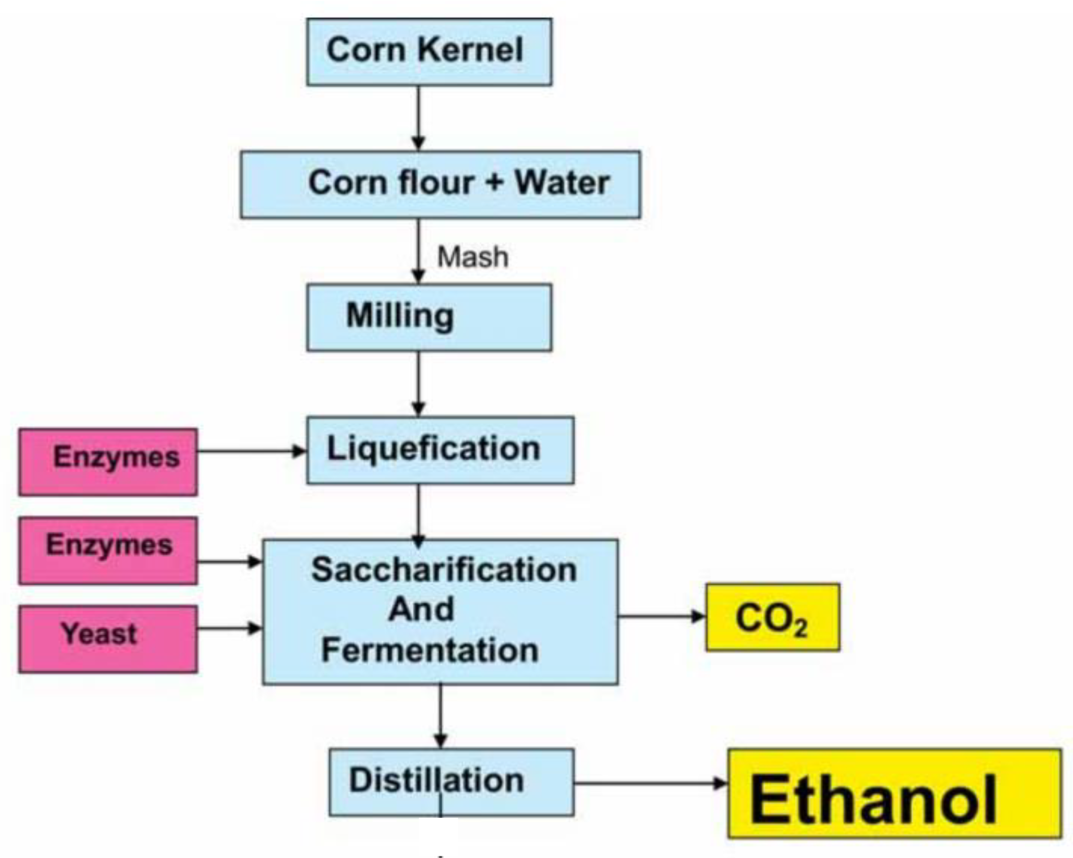
Figure 7.
Schematic diagram of the Valle Secolo dominant steam geothermal plant. The figure highlights the main components, including the turbine (T), mixers (M1 and M2), cooling tower (CT), and the compressors (C1 and C2) for extracting non-condensable gases.
Figure 7.
Schematic diagram of the Valle Secolo dominant steam geothermal plant. The figure highlights the main components, including the turbine (T), mixers (M1 and M2), cooling tower (CT), and the compressors (C1 and C2) for extracting non-condensable gases.
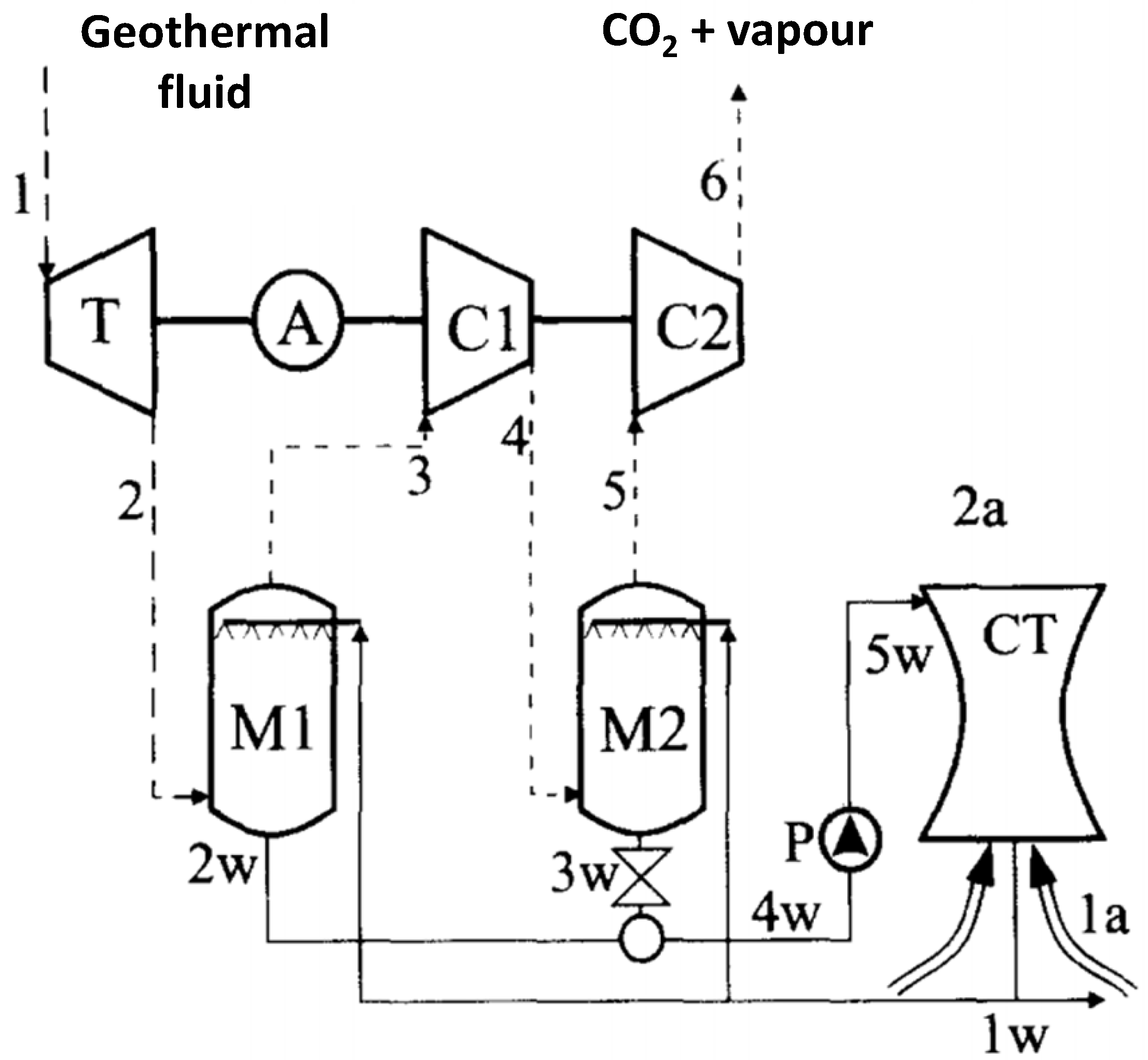

Table 1.
Molar mass, molar flow rate, mass flow rate, and lower heating value (LHV) of the chemical species involved in the co-electrolysis process.
Table 1.
Molar mass, molar flow rate, mass flow rate, and lower heating value (LHV) of the chemical species involved in the co-electrolysis process.
| Chemical species | Molar mass (g/mol) |
Moles [mol/s] |
Mass flow rate [kg/s] |
LHV [kJ/mol] |
LHV [MJ/kg] |
|---|---|---|---|---|---|
| H2O | 18.02 | 22.73 | 0.41 | ||
| CO2 | 44.01 | 22.73 | 1 | ||
| CO | 28.01 | 22.73 | 0.637 | 283.0 | 10.1 |
| H2 | 2.02 | 22.73 | 0.046 | 241.8 | 120 |
Table 2.
Summary of the theoretical power requirements for co-electrolysis process in ideal conditions, considering unitary mass flow rate of CO2 (1 kg/s).
Table 2.
Summary of the theoretical power requirements for co-electrolysis process in ideal conditions, considering unitary mass flow rate of CO2 (1 kg/s).
| Number of electrons [mol/s] |
Total charge [C/s] |
Minimum cell potential, E [V] |
P = Q x E [kW] |
|---|---|---|---|
| 90.92 | 8.76 × 10⁶ | 1.46 | 12680.9 |
Table 3.
Comparison between electrolysis and co-electrolysis.
| Parameter | Water Electrolysis (H₂O → H₂ + ½O₂) |
Co-electrolysis (CO₂ + H₂O → CO + H₂) |
|---|---|---|
| Reactants required | ~9 kg H₂O | ~9 kg H₂O + ~22 kg CO₂ |
| Overall reaction | H₂O → H₂ + ½O₂ | CO₂ + H₂O → CO + H₂+ O₂ |
| Technology used | PEM / Alkaline / SOEC | SOEC |
| Operating temperature | 60–80 °C (ALK, PEM); 700–850 °C (SOEC) |
700–850 °C |
| ΔG° | ~ 237 kJ/mol H₂ | ~ 257 kJ/mol H₂ |
| Minimum energy required | 39,6 kWh/kg H₂ | 42,7 kWh/kg H₂ |
| Electrical energy input | 55-60 kWh/kg H₂ | 79–84 kWh/kg H₂ |
| Thermal energy input (net) | ~0–1 kWh/kg H₂ | ~5–10 kWh/kg H₂ |
| Total energy required | ~55–61 kWh/kg H₂ | ~84–94 kWh/kg H₂ |
| Main product gas | H₂ | Syngas (H₂ + CO) |
| CO₂ processed per kg of H₂ | None | ~22 kg |
| Efficiency (on LHV basis) | ~60–70% | ~45–50% |
Table 4.
Process balances for co-electrolysis with efficiencies of 30% to 70% based on a reference mass flow rate of CO2 (1 kg/s).
Table 4.
Process balances for co-electrolysis with efficiencies of 30% to 70% based on a reference mass flow rate of CO2 (1 kg/s).
| Efficiency of co-electrolysis | Electricity required [kWh] |
Energy required for water vaporization | H2 mass flow rate [kg/h] |
CO mass flow rate [kg/h] |
H2 energy content [kWh] |
CO energy content [kWh] |
SEC for hydrogen prod. [kWh/kg] |
|---|---|---|---|---|---|---|---|
| 70% | 9100 | 3790 | 165,6 | 2293.2 | 5520 | 6435.7 | 77.8 |
| 50% | 12800 | 3790 | 165,6 | 2293.2 | 5520 | 6435.7 | 100.2 |
| 30% | 21330 | 3790 | 165,6 | 2293.2 | 5520 | 6435.7 | 151.7 |
Table 5.
Temperature influences the performance of co-electrolysis (estimated values).
| Operating Temperature [°C] |
Estimated perspective efficiency [%] |
|---|---|
| 50-80 | 20–30 |
| 200 | 30–40 |
| 400 | 40–50 |
| 600 | 50–60 |
| 800 | 60–70 |
Table 6.
Qualitative comparison between high temperature and low-temperature co-electrolysis.
| Factor | High-Temperature Co-Electrolysis |
Low-Temperature Co-Electrolysis |
|---|---|---|
| Energy Requirement | Lower electrical input, as heat provides part of the required energy. |
Higher electrical input needed, increasing energy consumption. |
| Reaction Kinetics | Faster reaction rates, improving efficiency. | Slower reaction rates, making the process inefficient. |
| Electrolyte Conductivity | Solid oxide electrolytes (e.g., YSZ) conduct oxygen ions efficiently. |
Poor ion conductivity at low temperatures, leads to high resistance. |
| Water Phase | Operates with steam, which enhances reaction efficiency. | Requires additional energy to convert liquid water into steam. |
| Overall Efficiency | Higher efficiency due to improved kinetics and lower electrical losses. | Lower efficiency, high losses, and impractical operation. |
| Cost Reduction | High manufacturing and operational costs | Possible use of low-cost materials |
Table 7.
Research areas in co-electrolysis, associated key challenges, and potential solutions.
| Research Area | Key Challenges | Potential Solutions & Directions |
|---|---|---|
| Electrode Materials & Catalysts |
Stability, efficiency, and resistance to degradation | Advanced perovskite oxides, transition metal doping, nanostructured catalysts |
| Electrochemical Performance |
Faradaic efficiency, current density, and reaction kinetics | Optimized doping, interface engineering, enhanced electrode architecture |
| Temperature Optimization |
High operating temperatures (700–900°C) increase thermal energy quality demand and material stress and thermal control | Exploring lower-temperature SOECs, hybrid approaches integrating PEM technology |
| H₂/CO Ratio Control |
Precise tuning for downstream applications (e.g., Fischer-Tropsch synthesis) | Adjusting feed gas composition, operating voltage, and catalyst properties |
| System Scalability |
Transitioning from laboratory-scale to industrial-scale applications | Modular SOEC stacks, integration with renewable energy sources |
| Durability & Degradation |
Long-term stability, anode/electrolyte interface degradation | Improved material selection, protective coatings, optimized operational strategies |
| Integration with Industrial Processes |
Compatibility with processes in which CO2 separation is required and sizing problem | Direct syngas utilization, coupling with carbon capture and utilization (CCU) technologies |
Table 8.
Estimated CO₂ emissions from a cement plant producing 1 million tons of clinker.
| Parameter | Value |
|---|---|
| Annual Cement Production | 1,000,000 tons/year |
| Daily Production | 1,000,000 tons ÷ 365 days = 2740 tons/day |
| Hourly Production | 2,740 tons ÷ 24 h = 114.17 tons/h |
| CO₂ Emissions from Calcination | 0.68 × 114.17 tons = 77.76 tons CO₂/hour |
| Annual CO₂ Emissions | 77.76 tons/hour × 24 h × 365 days = 681,000 tons CO₂/year |
Table 9.
Estimated CO₂ separation potential in natural gas processing facilities handling sour gas.
| Parameter | Value |
|---|---|
| Natural gas treated (per day) | 2,000,000 m³ |
| Initial CO₂ content (6% of total) | 120,000 m³ |
| CO₂ separation efficiency | 85% |
| CO₂ separated (per day) | 102,000 m³ |
| CO₂ residual (in treated gas) | 18,000 m³ |
| CO₂ separated (per year) | 37,230,000 m³ (approx. 37.23 million m³) |
| CO₂ separated (mass per day) | 102,000 m³ × 1.977 kg/m³ = 201,654 kg (201.65 tons) |
| CO₂ residual (mass per day) | 18,000 m³ × 1.977 kg/m³ = 35,346 kg (35.35 tons) |
Table 10.
CO₂ emissions from selected geothermal power plants worldwide.
| Geothermal Field | CO₂ Concentration (wt%) | CO₂ Emissions (kg/MWh) |
Reference |
|---|---|---|---|
| Monte Amiata (Italy) | ~5-8% | 250-520 | [32] |
| Larderello (Italy) | ~1-5% | Lower than Monte Amiata | [33] |
| The Geysers (USA) | ~0.5-2% | ~40-100 | [34] |
| Krafla (Iceland) | ~0.5-1.5% | ~10-50 | [35] |
| Taupo Volcanic Zone (NZ) | ~2-6% | ~100-300 | [36] |
| Philippines Fields | ~1-4% | ~50-200 | [37] |
Table 11.
Mass flow rate from geothermal plant of Valle Secolo, area of Larderello (data from [38]).
Table 11.
Mass flow rate from geothermal plant of Valle Secolo, area of Larderello (data from [38]).
| Point | m [kg/s] |
P [bar] |
T [°C] |
x CO2 |
|---|---|---|---|---|
| 1 | 111.11 | 5.00 | 195 | 5.0 |
| 2 | 111.11 | 0.08 | 41 | 5.0 |
| 3 | 7.65 | 0.07 | 26 | 72.6 |
| 4 | 7.65 | 0.272 | 177 | 72.6 |
| 5 | 6.10 | 0.260 | 33 | 91.1 |
| 6 | 6.10 | 1.013 | 176 | 91.1 |
Disclaimer/Publisher’s Note: The statements, opinions and data contained in all publications are solely those of the individual author(s) and contributor(s) and not of MDPI and/or the editor(s). MDPI and/or the editor(s) disclaim responsibility for any injury to people or property resulting from any ideas, methods, instructions or products referred to in the content. |
© 2025 by the authors. Licensee MDPI, Basel, Switzerland. This article is an open access article distributed under the terms and conditions of the Creative Commons Attribution (CC BY) license (http://creativecommons.org/licenses/by/4.0/).
Copyright: This open access article is published under a Creative Commons CC BY 4.0 license, which permit the free download, distribution, and reuse, provided that the author and preprint are cited in any reuse.


