Submitted:
06 August 2025
Posted:
07 August 2025
You are already at the latest version
Abstract
Designing the control system is a crucial phase in spacecraft development. Control systems come in various forms, typically including electrical actuators, cold gas thrusters, and monopropellant thrusters. Monopropellant micro-thrusters generate more thrust compared to other actuators and are more cost-effective for short space missions. This research focuses on the design of the propulsion system for hydrazine monopropellant thrusters on a space probe. Based on the required torque for attitude control, twelve micro-thrusters were utilized. Each axis is controlled by four actuators, with each actuator required to provide 10 Newtons of thrust. For this purpose, 10 N hydrazine thrusters were employed. The thrusters are arranged on the carrier within the biological capsule as two sets of four and two sets of two. Each set is designed modularly, meaning that the propellant tank and connections for each set are independent of the other sets. This study determined the necessary quantities of hydrazine and nitrogen gas, as well as the required tank volumes for the system.
Keywords:
monopropellant thruster
; hydrazine
; space probe
; propellant
; propulsion system
1. Introduction
Thrusters are essential for orbit correction and attitude control of satellites. Low-Earth orbit satellites often require impulsive propulsion for various purposes, including injecting the satellite into its mission orbit, drag compensation, increasing and decreasing satellite velocity along its trajectory, and position control across three axes. Hydrazine monopropellant thrusters are commonly used to provide the necessary propulsion for satellites [1,2].
Propulsion systems can be categorized into several groups based on their operation: cold gas thrusters, monopropellant thrusters, bipropellant thrusters, electric thrusters, and solid fuel thrusters. Monopropellant micro-thrusters offer high reliability and are typically used for satellite maneuvers. While hydrogen peroxide is a common fuel for monopropellant micro-thrusters, it tends to decompose spontaneously, even under optimal storage conditions [3,4,5,6].
Hydrazine is a viable alternative to hydrogen peroxide. Hydrazine decomposes in the presence of metal catalysts like iridium and platinum, making hydrazine thrusters simpler and more reliable than bipropellant thrusters. Hydrazine monopropellant thrusters are widely used in space missions due to their high reliability and have been extensively employed for satellite attitude control and orbit correction over the past few decades [7].
Lim [2] utilized four hydrazine monopropellant micro-thrusters for attitude control of the TacSat-4 satellite. When the fuel tank is full, each actuator produces 4.3 Newtons of thrust, which decreases to 1.6 Newtons as the tank pressure drops. The micro-thruster nozzle outlet can rotate by 10 degrees, generating torque along the x and y axes. The hydrazine actuators are positioned on the four sides of the satellite's service tray, with the fuel tank located in the center. All micro-thrusters are on a single plane [8].
As satellite missions become more complex, the demand for monopropellant thrusters has increased. A hydrazine monopropellant thruster consists of various components, including an injector, a catalyst bed, and a nozzle [9,10,11,12]. Liquid hydrazine from the thruster's tank is injected into the catalyst bed via the injector. The decomposition of hydrazine produces high-temperature gases in the catalyst bed, which then exit through a converging-diverging nozzle, generating thrust [3]. To control the attitude of the space probe under investigation, a 10 N hydrazine monopropellant micro-thruster was designed for this research [13,14,15]. Figure 1 illustrates the schematic of the micro-thruster, including the injector, decomposition chamber, nozzle, and other components. The micro-thruster configuration was developed using SolidWorks software. Figure 2 shows an image of the manufactured micro-thruster prototype by the authors. The design process for this micro-thruster can be found in reference [6,16,17,18,19,20,21].
While cold gas propulsion systems are prevalent in outer space and used by many satellites and rockets, hydrazine thrusters are more effective when entering dense atmospheres due to their ability to generate high thrust. Consequently, in the attitude control system of the present research's space capsule, 12 hydrazine monopropellant thrusters were employed. The design of the thruster feeding system and the final dimensions of the tanks will be determined in the following sections [4,22,23,24,25].
The thrusters within the biological capsule are mounted on the carrier in two sets of four and two sets of two. Each set is designed modularly, meaning that the propellant tank and connections for each set are independent of the other sets. As depicted in Figure 3, the feeding systems for the two sets of four thrusters are identical, and similarly, the feeding systems for the two sets of two thrusters are identical.
The following sections will detail the design of the thruster feeding system for each configuration. The feeding system comprises the propellant tank, tubing and fittings, filters, and valves.
2. Thruster Cluster Design
The space probe contains two dual-thruster clusters and two quad-thruster clusters, each with a separate feeding system. For hydrazine storage, a tank with a one-millimeter wall thickness is designed, made of stainless steel. There is a charge/discharge valve for nitrogen and another charge/discharge valve for charging or discharging hydrazine. A separate control valve is used for each actuator, and a burst disc and a filter are considered for the entire cluster. A pressure sensor is located on the tank. In this design (for the flight model), a temperature sensor will not be used [26,27,28].
The most critical parameter in determining the tank dimensions is the amount of propellant required for thruster operation. This depends on the specified thrust and specific impulse, and is solely contingent on the propulsion system's assigned mission and the duration for which the thruster must operate [29]. In missions where the required propellant volume is so small that it is comparable to the volume inside the tubes and fittings, the effect of the tube volume must definitely be considered in determining the required propellant. For a tank using a blow-down system, it is assumed that the initial pressure inside the tank is 25 bar and it can inject propellant to the injector head down to a pressure of 5 bar. In the calculations for this section, it was assumed that nitrogen gas is used for pressurization, and the ideal gas law was applied. It should be noted that the mission duration is 165 seconds, and all calculations are based on this time.
The specifications for the dual-thruster and quad-thruster cluster tanks are presented in Table 1 and Table 2, respectively. The circuit layout of the dual-thruster and quad-thruster cluster systems for the space prototype are shown in Figure 4 and Figure 5, respectively. The elements considered in these designs include:
- Propellant Gas Charge/Discharge Valve: Used for injecting the pressurizing agent gas or for purging the tank during hydrazine charging.
- Hydrazine Propellant Charge/Discharge Valve: Used for injecting propellant into the tank or discharging unused excess propellant.
- Tank and PMD (Propellant Management Device): This equipment is essential for safely storing propellant, providing the necessary pressure, and ensuring continuous propellant injection to the actuator's injector head in zero-gravity conditions.
- Filter: Necessary to remove propellant contaminants to prevent clogging of the injector orifice. The filter's flow cross-section is selected to be 40 microns based on the injector orifice size, and its material is compatible with hydrazine.
- Flow Control Valve: Used to open and close the flow path to the actuator for thrust control.
- Thruster: Equipment that converts the chemical energy of the propellant into thermal and kinetic energy by spraying hydrazine onto a catalyst.
3. Flow Control Valve
Flow control valves (Figures X and Y) are widely used in various industries to control the mass flow rate of liquids and gases at different operating pressures. Therefore, they can be categorized from several perspectives, the most important of which are [26]:
- Flow Type: Divided into two categories: constant flow and variable (adjustable) flow.
- Valve Mechanism Type: Can be poppet or piston, diaphragm, ball, or other types.
- Actuation Type: Can be solenoid, pneumatic, or other types.
- Valves with/without Pressure Compensator System: These are capable of automatically maintaining a constant fluid flow rate despite pressure fluctuations.
- Normally Closed or Normally Open: This refers to the valve's status prior to actuation.
Figure 6.
Solenoid Valve in Electrical Actuation Mode.
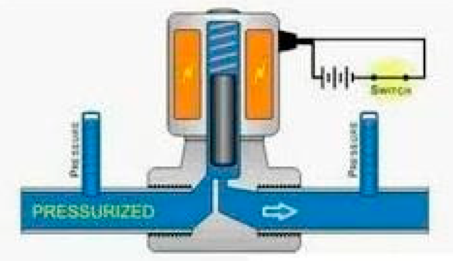
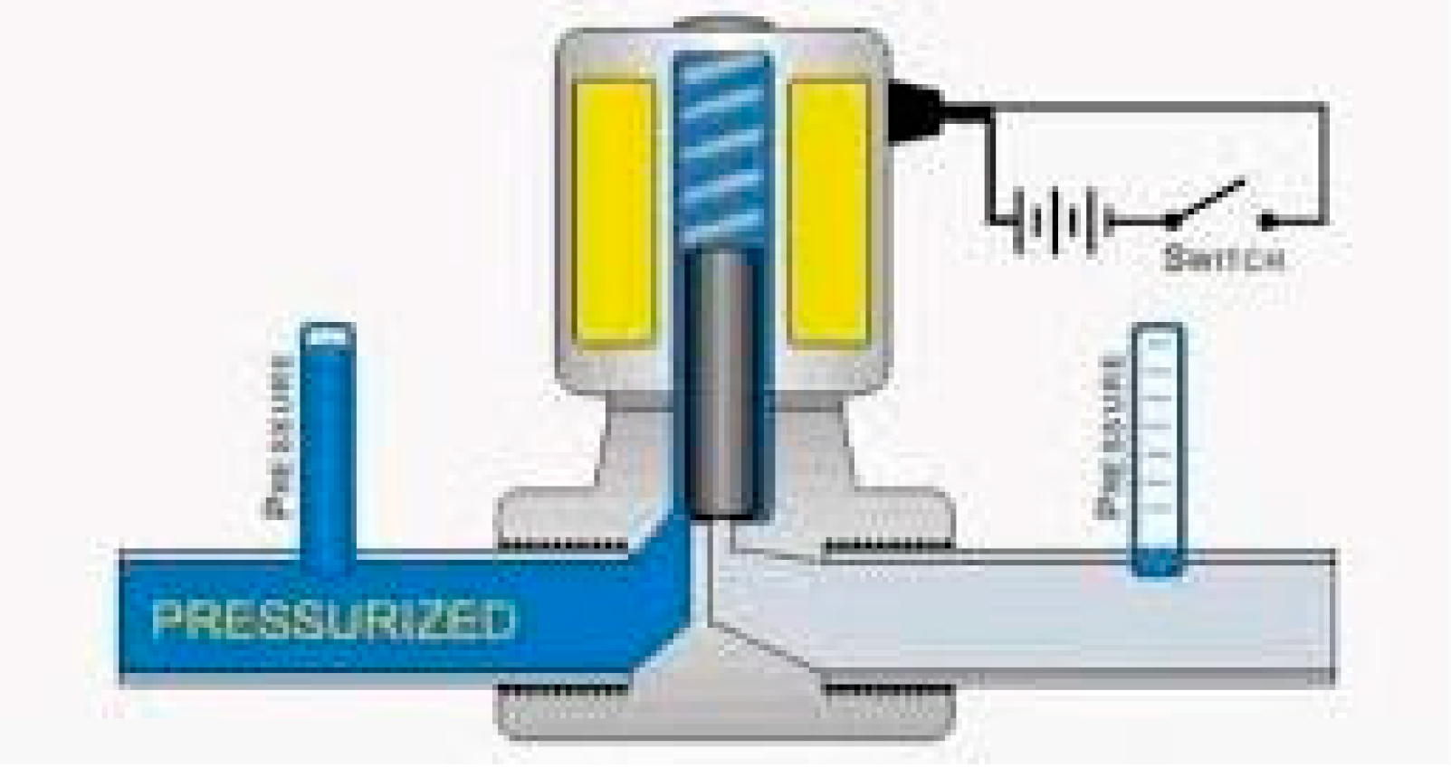
Figure 7.
Solenoid Valve in De-energized State.
Regarding flow control valves for ground testing, weight and power consumption are not significant concerns. Therefore, readily available commercial models with either electrical or pneumatic actuation can be used [30]. It's important to note that the seal material of these valves can be modified for use with different fluids.
BURKET solenoid flow control valves come in both normally closed and normally open types, and can handle fluid temperatures ranging from -10°C to 90°C. Their body material can be brass or stainless steel.
Two models of Parker solenoid flow control valves were selected for thruster application. The first model is normally open and can be used at pressures over 21 bar. However, due to its normally open configuration, it's not a suitable option. The second type of valve, a normally closed model, can withstand pressures up to 40 bar and has a maximum operating temperature slightly above 90°C, making it a suitable choice for ground test thrusters. A view of this valve model is shown in Figure 8.
After designing the feeding system for the hydrazine thrusters on the space probe, the schematic of their dual cluster assembly was drawn in SolidWorks, as shown in Figure 9. As mentioned, the feeding system for each thruster cluster is independent, and based on this, four hydrazine tanks and their accessories are installed in the space probe.
4. Conclusions
Suborbital spaceflight with living organisms is a mission that space probes have undertaken to advance technology and send life into space. These capsules aim to provide suitable in-flight conditions and ensure the safe and timely recovery and landing of the living organism. This imposes specific systemic, technical, and operational requirements and constraints on all the capsule's subsystems. Among the most critical of these is the propulsion system design.
The thrust for satellite attitude control and thruster operation can be provided through various methods. Monopropellant thrusters generate more thrust compared to other methods. Accordingly, this research focused on the design of a hydrazine thruster feeding system, and the dimensions of the propellant tanks were determined. Furthermore, other components of the feeding system, such as valves, were selected based on their pressure tolerance and corrosion resistance to hydrazine.
References
- Ley, H.; Wittmann, K.; Hallmann, W. Handbook of space technology; 2009. [Google Scholar]
- Saboohi, Z.; Moradi, A.; Hosseini, S.E.; Karimi, N. Experimental investigation of atmospheric boundary layer using unmanned aerial system equipped with novel measurement system. Meteorol. Atmos. Phys. 2025 1371 2025, 137, 1–17. [Google Scholar] [CrossRef]
- Lim, T.W. Thruster attitude control system design and performance for Tactical Satellite 4 maneuvers. J. Guid. Control. Dyn. 2014, 37, 403–412. [Google Scholar] [CrossRef]
- Davari, S.; Ommi, F.; Saboohi, Z.; Hosseini, S.E. Hybrid Multi-Objective Optimization of Gas Turbine Combustor to Reduce Non-Volatile Particulate Matter and Gaseous Emissions. 2025. [Google Scholar] [CrossRef]
- Sabohi, Z.; Hosseini, S.E. Advancements in Biogas Production: Process Optimization and Innovative Plant Operations. Clean Energy 2024. [Google Scholar] [CrossRef]
- Hosseini, S.E.; Jafaripanah, S.; Saboohi, Z. CFD simulation and aerodynamic optimization of two-stage axial high-pressure turbine blades. J. Brazilian Soc. Mech. Sci. Eng. 2024, 46, 1–20. [Google Scholar] [CrossRef]
- Davari, S.; Hosseini, S.E. A review on the oxygenated fuels on engine performance parameters and emissions of spark ignition engines. OSF 2025. [Google Scholar] [CrossRef]
- Jamshidi, D.; Poureyvaz Borazjani, D.; Hosseini, S.E.; Davari, S. Impact of Exhaust Manifold Design on Internal Combustion Engine Performance. 2025. [Google Scholar] [CrossRef]
- Liu, Y.; Lu, B.; Kong, X.; Chen, H. Experimental study on the outlet flow field and cooling performance of vane-shaped pre-swirl nozzles in gas turbine engines. Case Stud. Therm. Eng. 2023, 44, 102878. [Google Scholar] [CrossRef]
- Jofre-Reche, J.A.; Pulpytel, J.; Fakhouri, H.; Arefi-Khonsari, F.; Martín-Martínez, J.M. Surface Treatment of Polydimethylsiloxane (PDMS) with Atmospheric Pressure Rotating Plasma Jet. Modeling and Optimization of the Surface Treatment Conditions. Plasma Process. Polym. 2016, 13, 459–469. [Google Scholar] [CrossRef]
- Hosseini, S.E.; Deyranlou, A.; Talebizadehsardari, P.; Mohammed, H.I.; Keshmiri, A. Developing a numerical framework to study the cavitation and non-cavitation behaviour of a centrifugal pump inducer. Int. J. Nav. Archit. Ocean Eng. 2024, 16, 100606. [Google Scholar] [CrossRef]
- Mardani, A.; Bahonar, H.; Beige, A.A. Experimental investigation of flame state transition in a gas turbine model combustor by analyzing noise characteristics. Phys. Fluids 2023, 35. [Google Scholar] [CrossRef]
- Davari, S.; Ommi, F.; Saboohi, Z. Investigating the Effects of Adding Butene, Homopolymer to Gasoline on Engine Performance Parameters and Pollutant Emissions : Empirical Study and Process Optimization. J. Inst. Eng. Ser. C 2021. [Google Scholar] [CrossRef]
- Saberi, F.F.; Mehdi, Z. Design and Analysis of Gimbal Thruster Configurations for 3-Axis Satellite Attitude Control. Int. J. Comput. Appl. 2015, 112, 29–38. [Google Scholar]
- Hosseini, S.E.; Keshmiri, A. Experimental and numerical investigation of different geometrical parameters in a centrifugal blood pump. Res. Biomed. Eng. 2022, 38, 423–437. [Google Scholar] [CrossRef]
- Davari, S.; Ommi, F.; Saboohi, Z.; Safar, M. Experimental study of the effect of a non-oxygenated additive on spark-ignition engine performance and pollutant emissions. Int. J. Eng. Trans. A Basics 2021, 34, 1035–1045. [Google Scholar] [CrossRef]
- Rysanek, F.; Hartmann, J.W.; Applied, A.; Corporation, S.; Ave, P.; Leandro, S.; Rysanek, F. MicroVacuum Arc Thruster Design for a CubeSat Class Satellite. In Proceedings of the Small Satellite Conference; 2002; pp. 1–7. [Google Scholar]
- Bontempo, R.; Manna, M. Effects of the duct thrust on the performance of ducted wind turbines. Energy 2016, 99, 274–287. [Google Scholar] [CrossRef]
- Shojaeefard, M.H.; Hosseini, S.E.; Zare, J. Numerical simulation and multi-objective optimization of the centrifugal pump inducer. Modares Mech. Eng. 2018, 17, 205–216. Available online: http://mme.modares.ac.ir/article-15-15078-en.html.
- Hosseini, S.E.; Saboohi, Z. Ducted wind turbines: A review and assessment of different design models. Wind Eng. 2024, 1–22. [Google Scholar] [CrossRef]
- Delaval, M.N.; Jonsdottir, H.R.; Leni, Z.; Keller, A.; Brem, B.T.; Siegerist, F.; Schönenberger, D.; Durdina, L.; Elser, M.; Salathe, M.; et al. Responses of reconstituted human bronchial epithelia from normal and health-compromised donors to non-volatile particulate matter emissions from an aircraft turbofan engine. Environ. Pollut. 2022, 307. [Google Scholar] [CrossRef]
- Hosseini, S.E.; Salehi, F. Analyzing overlap ratio effect on performance of a modified Savonius wind turbine. Phys. Fluids 2023, 35, 125131. [Google Scholar] [CrossRef]
- Onwosi, C.O.; Ozoegwu, C.G.; Nwagu, T.N.; Nwobodo, T.N.; Eke, I.E.; Igbokwe, V.C.; Ugwuoji, E.T.; Ugwuodo, C.J. Cattle manure as a sustainable bioenergy source: Prospects and environmental impacts of its utilization as a major feedstock in Nigeria. Bioresour. Technol. Reports 2022, 19, 101151. [Google Scholar] [CrossRef]
- Ghimire, A.; Gyawali, R.; Lens, P.N.L.; Lohani, S.P. Technologies for removal of hydrogen sulfide (H2S) from biogas. Emerg. Technol. Biol. Syst. Biogas Upgrad. 2021, 295–320. [Google Scholar] [CrossRef]
- Hosseini, S.E.; Karimi, O.; AsemanBakhsh, M.A. Experimental investigation and multi-objective optimization of savonius wind turbine based on modified non-dominated sorting genetic algorithm-II. Wind Eng. 2024, 48, 446–467. [Google Scholar] [CrossRef]
- Davari, S.; Ommi, F.; Saboohi, Z.; Hosseini, S.E. Conceptual Design of a Conventional Aero Gas Turbine Combustor for Soot and Gaseous Emissions Reduction. J. Engine Res. 2025. [Google Scholar]
- Shojaeefard, M.H.; Hosseini, S.E.; Zare, J. CFD simulation and Pareto-based multi-objective shape optimization of the centrifugal pump inducer applying GMDH neural network, modified NSGA-II, and TOPSIS. Struct. Multidiscip. Optim. 2019, 60, 1509–1525. [Google Scholar] [CrossRef]
- Lee, D.; Yang, S. Surface modification of PDMS by atmospheric-pressure plasma-enhanced chemical vapor deposition and analysis of long-lasting surface hydrophilicity. Sensors Actuators B Chem. 2012, 162, 425–434. [Google Scholar] [CrossRef]
- Zare, J.; Hosseini, S.E.; Rastan, M.R. Airborne dust-induced performance degradation in NREL phase VI wind turbine: a numerical study. Int. J. Green Energy 2024, 21, 1295–1314. [Google Scholar] [CrossRef]
- Davari, S.; Ommi, F.; saboohi, Z. Experimental study of the effects of adding methylated homopolymer to gasoline on the engine performance and pollutant emissions. J. Solid Fluid Mech. 2021, 11, 199–210. [Google Scholar] [CrossRef]
Figure 1.
3D View of the Micro-thruster.
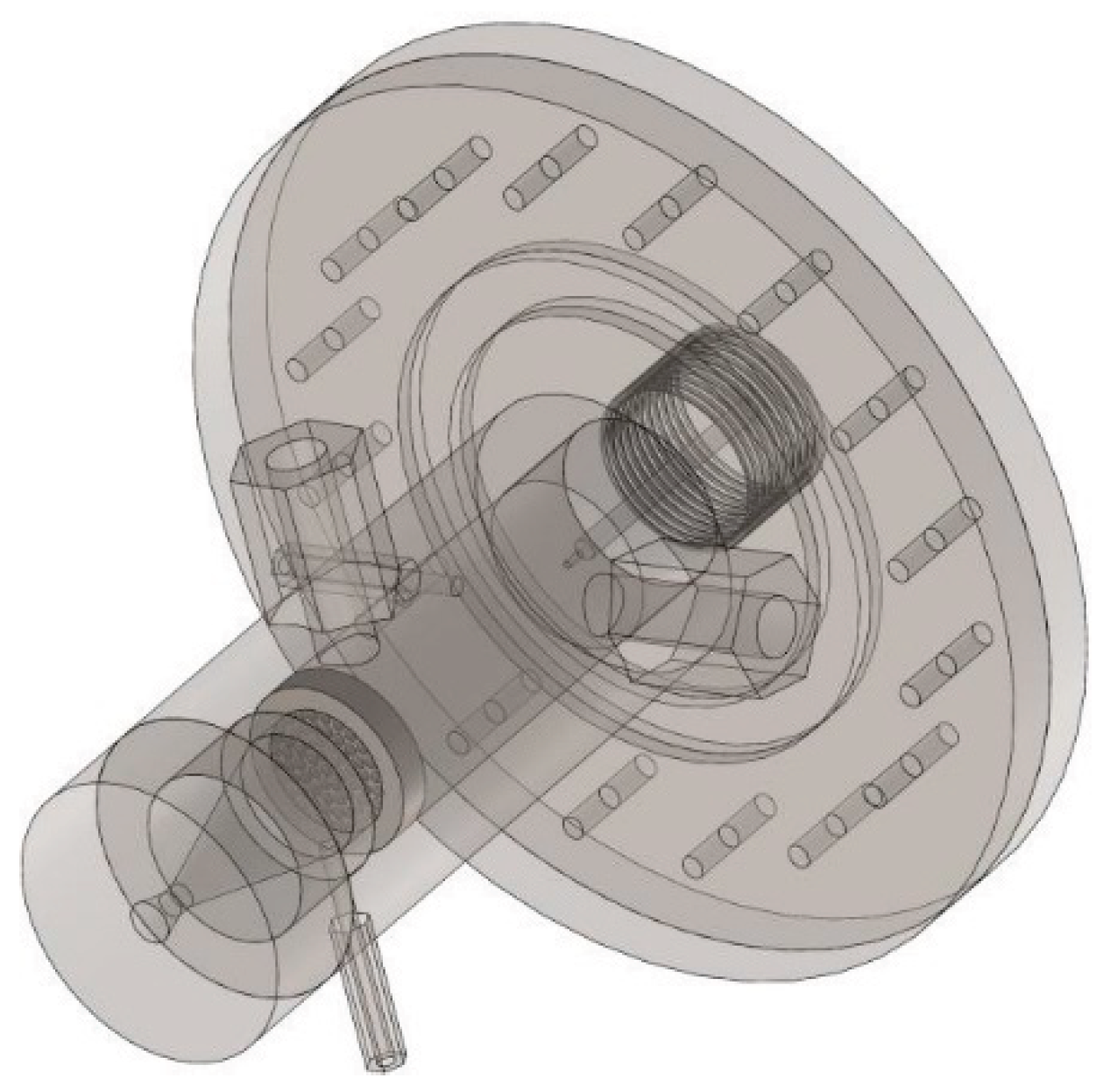
Figure 2.
Micro-thruster Prototype.
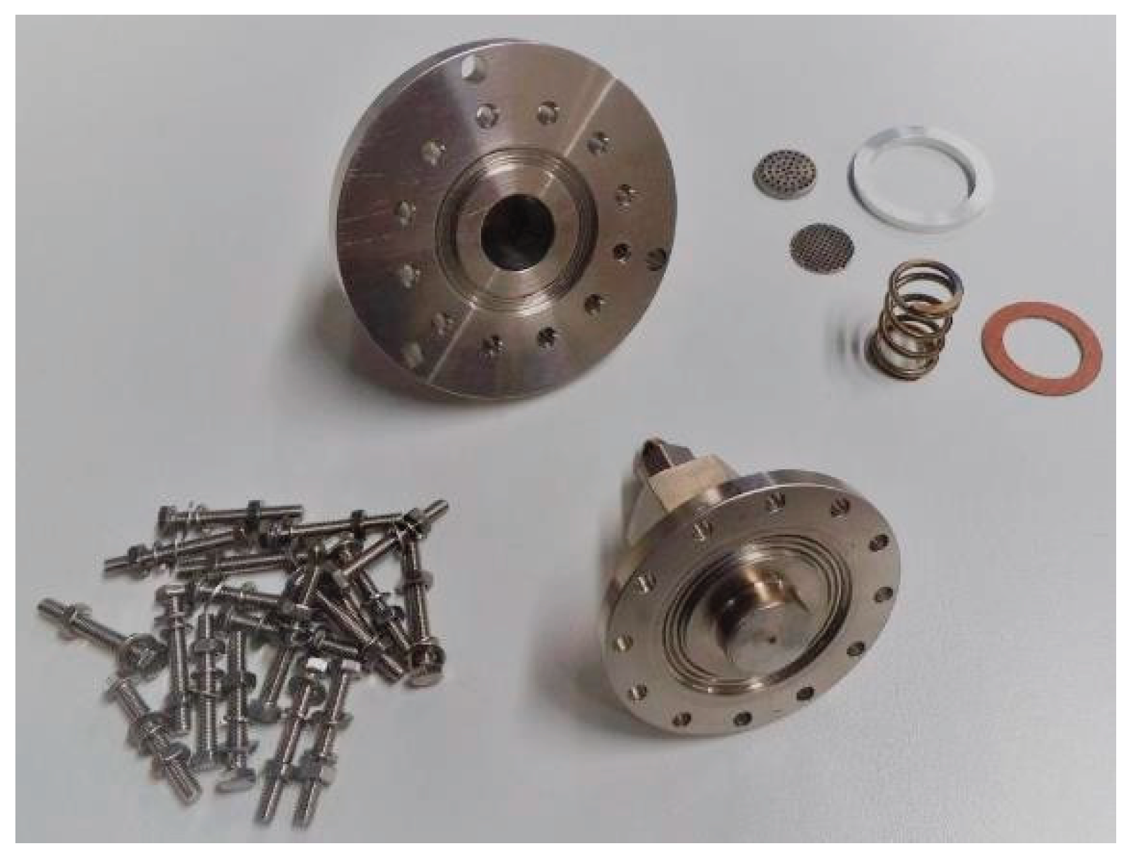
Figure 3.
- Arrangement of Thruster Clusters on the Space Probe.
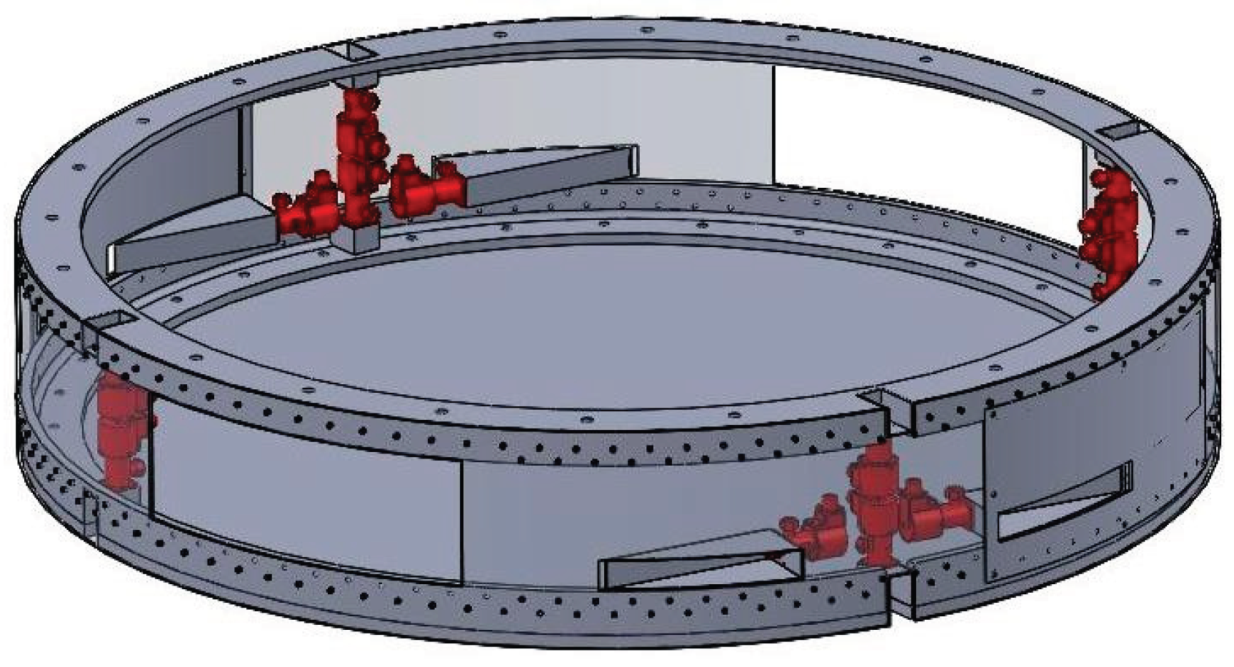
Figure 4.
Circuit Layout of the Dual Thruster Cluster System.
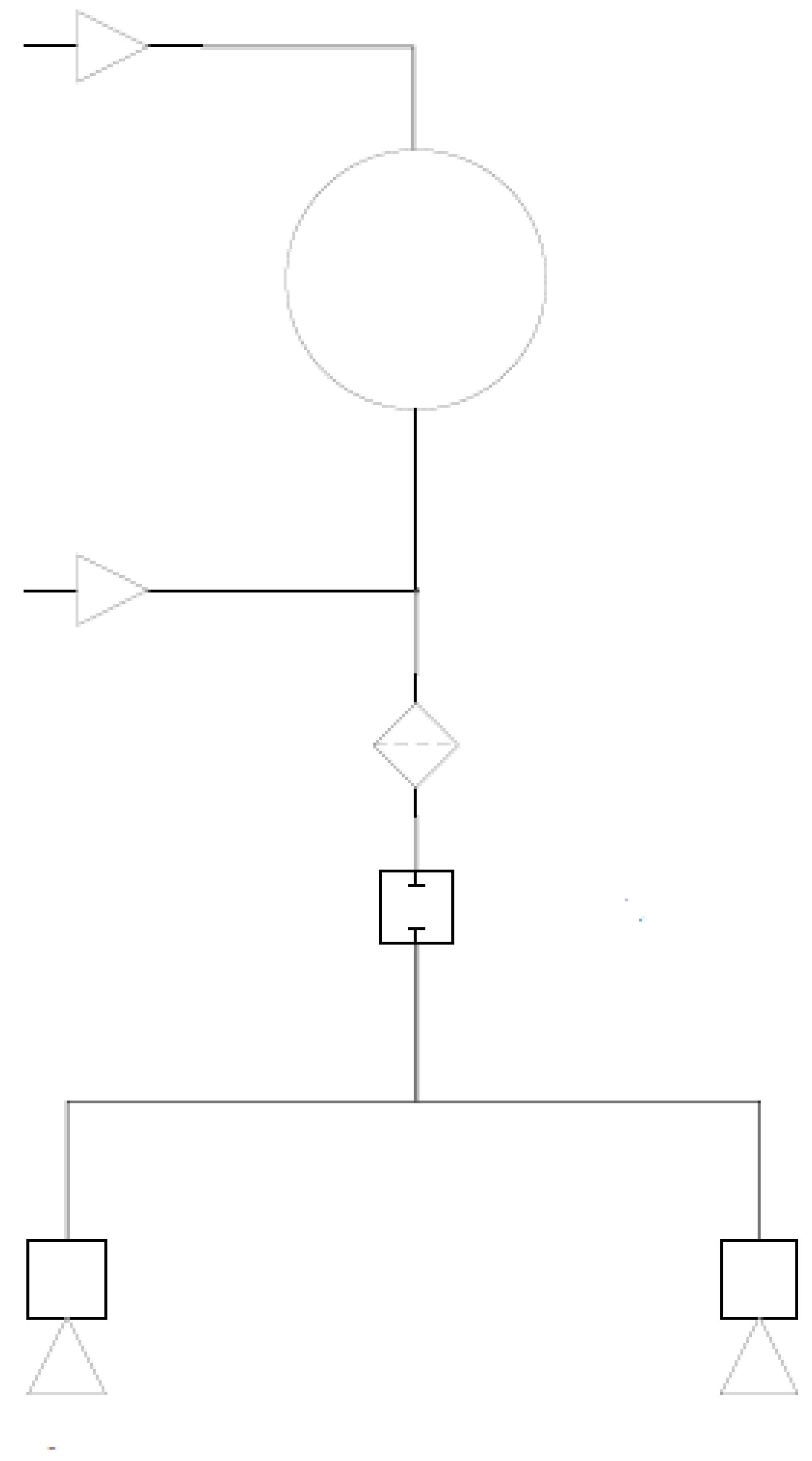
Figure 5.
Circuit Layout of the Quad Thruster Cluster System.
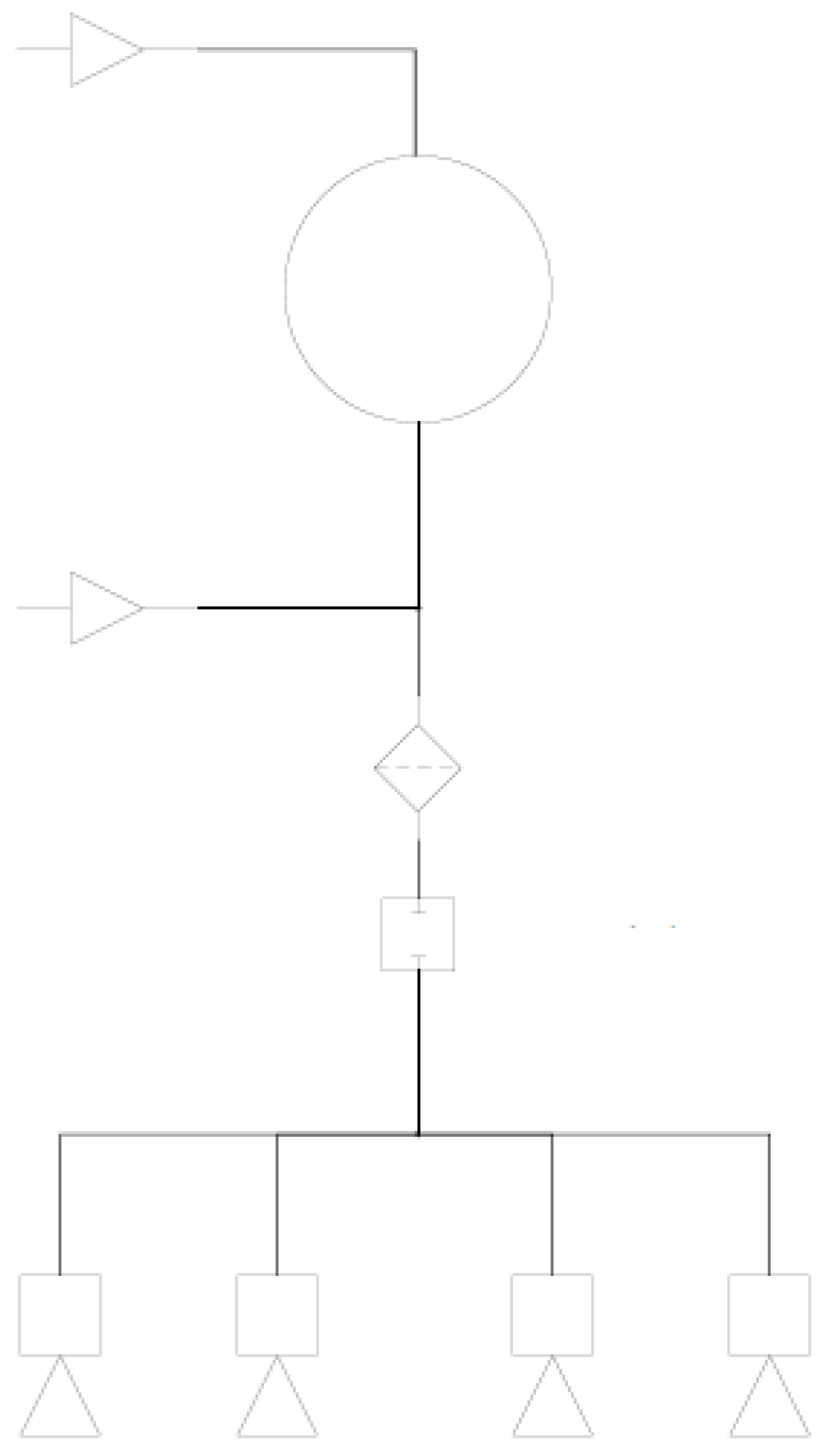
Figure 8.
- An Example of a Parker Flow Control Valve with Diverse Applications, Including Fuel On/Off Control at 40 Bar.
Figure 8.
- An Example of a Parker Flow Control Valve with Diverse Applications, Including Fuel On/Off Control at 40 Bar.

Figure 9.
3D Schematic of the Hydrazine Thruster Dual Cluster Feeding System.
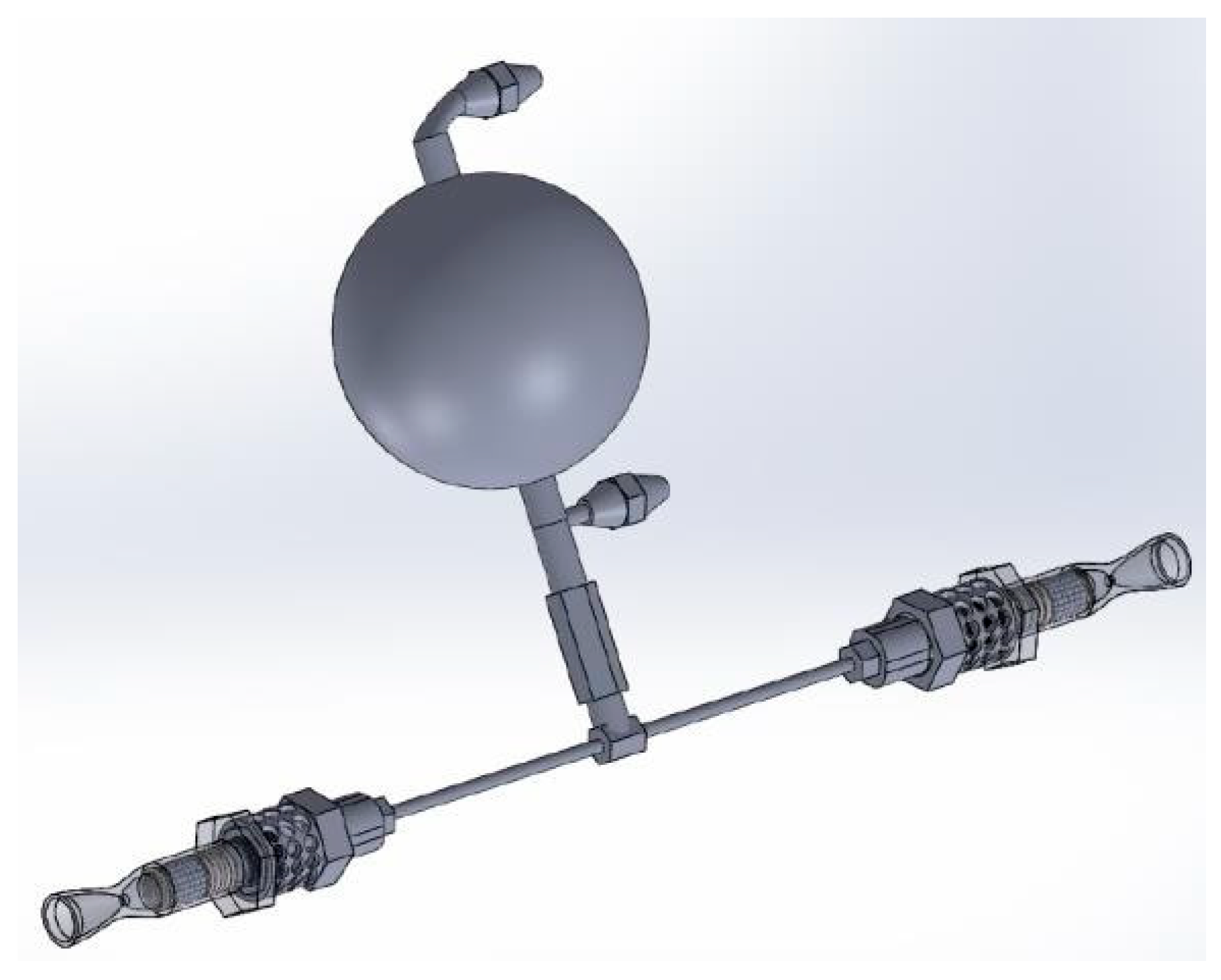

Table 1.
Volumetric and Pressure Specifications for the Dual Thruster Cluster Tank.
| Parameter | Quantity | Unit |
| Hydrazine Propellant Mass | 1.98 | kg |
| Hydrazine Propellant Volume | 1.94 | lit |
| Nitrogen Pressurant Gas Volume | 0.63 | lit |
| Gas to Liquid Volume Ratio in Tank | 0.33 | - |
| Tank Radius | 8.5 | cm |
| Tank Volume | 2.58 | lit |
| Dry Tank Mass | 0.72 | kg |
| Tank Operating Pressure | 21.5 | bar |
| Maximum Tank Operating Pressure | 25 | bar |
| Tank Burst Pressure | 40 | bar |
Table 2.
Volumetric and Pressure Specifications for the Quad Thruster Cluster Tank.
| Parameter | Quantity | Unit |
| Hydrazine Propellant Mass | 3.96 | kg |
| Hydrazine Propellant Volume | 3.88 | lit |
| Nitrogen Pressurant Gas Volume | 0.97 | lit |
| Gas to Liquid Volume Ratio in Tank | 0.25 | - |
| Tank Radius | 10.5 | cm |
| Tank Volume | 4.85 | lit |
| Dry Tank Mass | 1.1 | kg |
| Maximum Tank Operating Pressure | 25 | bar |
| Tank Burst Pressure | 40 | bar |
Disclaimer/Publisher’s Note: The statements, opinions and data contained in all publications are solely those of the individual author(s) and contributor(s) and not of MDPI and/or the editor(s). MDPI and/or the editor(s) disclaim responsibility for any injury to people or property resulting from any ideas, methods, instructions or products referred to in the content. |
© 2025 by the authors. Licensee MDPI, Basel, Switzerland. This article is an open access article distributed under the terms and conditions of the Creative Commons Attribution (CC BY) license (http://creativecommons.org/licenses/by/4.0/).
Copyright: This open access article is published under a Creative Commons CC BY 4.0 license, which permit the free download, distribution, and reuse, provided that the author and preprint are cited in any reuse.


