
Submitted:
13 June 2025
Posted:
17 June 2025
You are already at the latest version
Abstract
In both scientific and industrial fields, there has been a notable increase in attention toward High-Altitude Pseudo-Satellites (HAPS) in recent years. This surge is driven by their distinct advantages over traditional satellites and Remotely Piloted Aircraft Systems (RPAS). These benefits are particularly evident in critical areas such as intelligent transportation systems, surveillance, remote sensing, traffic and environmental monitoring, emergency communications, disaster relief efforts, and the facilitation of large-scale temporary events. This review provides an overview of key aspects related to the propellers and propulsion systems of HAPS. Firstly, an analysis of the propulsion systems proposed in literature or employed by HAPS is presented, focusing on both the technical challenges and advancements in this emerging field. Given that propellers remain the most efficient propulsor for such applications, the discussion then shifts to the fundamental principles of propeller theory, followed by an overview of innovative design methodologies proposed in literature for propellers intended for high-altitude operations and a discussion concerning methodologies for evaluating their performance. The unique atmospheric conditions at high altitudes result in distinct characteristics for the propellers of stratospheric airships compared to conventional ones.
Keywords:
HAPS
; Stratospheric Propellers
; Propulsion systems
1. Introduction
In recent years, there has been a growing interest in unmanned stratospheric platforms for long-duration Earth observation and telecommunications, commonly referred to as High Altitude Platform Systems (HAPS). These platforms represent a valuable complement to satellites and Remotely Piloted Aircraft Systems (RPAS). Most HAPS operate at altitudes of approximately 18–20 km, which are well above commercial air traffic. At these altitudes, the atmospheric conditions are relatively stable, with minimal convective activity and nearly constant temperatures. Wind speeds are also generally lower compared to those observed in both lower and higher atmospheric layers, making this region of the stratosphere particularly attractive for persistent operations.
This segment of the atmosphere is part of what is often referred to as Near Space, qualitatively defined as the region extending from around 20 km altitude up to the Kármán line at 100 km. Earth observation from the stratosphere benefits from the proximity to the Earth’s surface, enabling higher spatial resolution than satellite imagery, assuming equivalent optical payload characteristics. Furthermore, temporal resolution is significantly enhanced, as HAPS can maintain a fixed position (station-keeping), thereby eliminating or substantially reducing revisit times. Until recently, HAPS technologies had received limited attention. However, several configurations have now been proposed and can generally be classified into two main categories, based on their method of lift generation: fixed-wing platforms and lighter-than-air systems. Among the fixed-wing solutions, the Airbus Zephyr platform [1] and the AE Prismatic PHASA-35 system [2] show considerable promise. In the category of lighter-than-air systems, Thales is developing the Stratobus airship [3], while the SCEYE airship [4] has already completed multiple missions in the stratosphere. These platforms differ in configuration and payload capacity, which can range from a few kilograms (5–20 kg) to several hundred kilograms, depending on the specific design.
Hybrid configurations have also been explored in the literature. For example, the Italian Aerospace Research Centre (CIRA) is actively developing a hybrid solution that combines both aerostatic and aerodynamic lift, as detailed in [5,6].
One of the most critical subsystems in HAPS is the propulsion system, due to its significant impact on both power consumption and overall system weight. Achieving the required endurance and payload capacity at stratospheric altitudes and relatively low flight speeds presents a substantial challenge. The most feasible approach to address this issue is the adoption of propulsion systems characterized by high efficiency and low specific energy consumption.
The design of propulsion systems for HAPS has undergone significant evolution over the past decades, primarily driven by technological advancements in renewable energy sources (e.g., photovoltaic systems) and energy storage technologies (e.g., batteries). In [7], a study is presented on a propulsion system for a subsonic, high-altitude unmanned aircraft capable of operating at an altitude of approximately 100,000 ft, with a loiter time of about three hours. The propulsion system in that case consisted of a turboprop engine fueled by onboard fuel and oxidizer.
At the time of publication [7], the endurance record at 65,000 ft was held by the Boeing Condor UAV, which achieved 58 hours of continuous flight using a liquid-cooled, two-stage turbocharged spark-ignition engine. A key challenge associated with air-breathing turbocharged piston engines at high altitudes is heat rejection, due to the low ambient air density. This necessitates the use of larger radiators. In addition, achieving effective combustion requires very high pressure ratios to compensate for the low atmospheric pressure.
In [8], a comparative study is provided, analyzing various propulsion system types for a High-Altitude Long-Endurance (HALE) airship across two mission profiles at altitudes between 60,000 and 70,000 ft, each with a target endurance of one month. The primary difference between the two scenarios lies in the payload mass. The authors evaluate four propulsion technologies: solar photovoltaic arrays, hydrogen fuel cells, rechargeable batteries, turboshaft engines powered by hydrogen, and regenerative fuel cells. At that time, prototype regenerative fuel cells could deliver approximately 400 Wh/kg, with projected capabilities reaching 700 Wh/kg. According to the analysis in [8], turboshaft or turboprop engines—potentially hydrogen-fueled—remained the most favorable solution for high-altitude propulsion, as they offered a lower propulsion-system-to-total-mass ratio compared to other alternatives.Two critical design requirements are emphasized in [9]: the propulsion system must be extremely lightweight and highly reliable, and must be able to operate at temperatures as low as 217 K. An additional challenge is the requirement for operation across a wide altitude range, as the platform must be capable of reaching and maintaining very high altitudes. Although propellers remain the preferred choice for many near-space aircraft, the authors of [9] also investigate unconventional propulsion concepts, including those based on electrohydrodynamic forces, radiometric forces, and thermal transpiration. However, these emerging technologies are not yet viable, mainly due to the limited understanding of the underlying physical mechanisms and the presence of multiple unresolved engineering challenges. Historically, one of the main obstacles in the practical deployment of HAPS has been the limited efficiency of solar cells and the relatively low energy density of battery systems. At present, HAPS are typically powered by solar energy during daylight hours and rely on battery storage during nighttime operations. This architecture is motivated by findings reported in [10], where the authors compare various UAV platforms powered by different energy sources, including combustion engines, regenerative fuel cells, solar energy, and batteries. While most of the UAVs analyzed are tropospheric in nature, the Airbus Zephyr HAPS is also included as a case study due to its reliance on solar energy for propulsion.
The study concludes that, compared to combustion systems and regenerative fuel cells, solar energy combined with battery storage offers the most favorable performance in terms of flight time-to-total weight ratio, payload weight-to-flight time ratio, and flight time-to-cost ratio. These advantages have significantly contributed to the growing viability and development of HAPS technology [11]. In early studies on HAPS platforms, battery energy densities were approximately 100 Wh/kg. Subsequent technological advancements led to an increase to 250 Wh/kg [12]. In 2022, Amprius Technologies (USA) announced the commercial availability of lithium-ion battery cells with an energy density of 450 Wh/kg and a volumetric density of 1150 Wh/L [13]. Similarly, MicroLink Devices (USA), a manufacturer of solar arrays for both satellite and HAPS applications, has developed high-efficiency solar sheets capable of delivering over 1.5 kW/kg, with a solar energy conversion efficiency of up to 37.75% [14]. Fuel cell technology has also progressed substantially. Since 2009, when state-of-the-art systems delivered power densities of around 400 W/kg, the technology has advanced considerably, with current systems reaching up to 1.6 kW/kg and targets as high as 2 kW/kg set by key stakeholders in the aviation sector [15]. Regardless of the energy source, most contemporary HAPS concepts—across various stages of development—employ electric propulsion systems, wherein electric motors drive lightweight, high-efficiency propellers. For low-speed applications typical of stratospheric flight, propellers continue to represent the most efficient propulsion method [16]. When integrated with renewable energy sources such as solar panels, these systems offer not only high precision and reliability, but also enable the long-duration, continuous operations that are essential for sustained HAPS missions in the stratosphere. Some of the most representative HAPS configurations developed over the past 40 years, each of which has successfully completed at least one flight, are presented in Figure 1 and Figure 2, along with their corresponding altitude and endurance performance data. The year indicated for each platform refers to the date when the performance was actually achieved or to the year in which such performance is expected to be reached on the basis of the design specifications. The data illustrated in these figures clearly demonstrate that, on average, HAPS equipped with electric propulsion systems tend to achieve superior altitude and endurance capabilities compared to those powered by combustion-based propulsion.
As a result, two main categories of HAPS can currently be identified: solar-powered airplanes and solar-powered airships [27]. Among the most notable solar airplane projects, both past and present, are Helios [28], AEV-3 [29], Aquila [30], Zephyr [31], and Cai-Hong [32]. Regarding solar airships, key projects include HiSentinel [33], the Stratospheric Platform (SPF) [34], the Korean Stratospheric Airship Program [27], the High-Altitude Airship (HAA) [35], and Stratobus [27].
To achieve high endurance capabilities at high altitudes, it is essential not only to improve engine efficiency but also to properly design propellers to enhance their performance. A key factor in propeller design and operation is the environment in which it functions. High-altitude conditions (ranging from 17 km up to 50 km) present unique challenges for propeller operation. At these altitudes, airfoils operate under low Reynolds number conditions, typically between and [36]. Within this range, the transition from laminar to turbulent flow plays a crucial role, with viscous forces becoming a significant factor influencing flow behavior. Compared to high Reynolds number operations, some of the most notable effects include a sharp decrease in the lift-to-drag ratio after its maximum, caused by the development of thicker boundary layers; possible nonlinear behavior of airfoils at low angles of attack; laminar flow separation along the blades leading to short or long laminar separation bubbles; increased sensitivity of the flow to free-stream turbulence; and a consequent rise in drag forces resulting in reduced efficiency [36,37,38].
The laminar separation bubble is a primary factor contributing to the decrease in propeller efficiency at very low Reynolds numbers [39]. The key to designing an effective propeller lies in mitigating the detrimental effects of laminar separation bubbles on the blades [40]. Furthermore, the interactions between three-dimensional effects, such as centrifugal [41,42] and Coriolis forces, with the transition process and the development of laminar separation bubbles along the blade, are not yet fully understood. These three-dimensional effects, amplified by blade rotation, can induce cross-flow within the boundary layer and alter the transition location, thereby influencing both the extent and stability of laminar separation [43]. Traditional low-fidelity methods, such as blade element momentum (BEM) theory and lifting-line theory, are unable to accurately capture these mechanisms, particularly under low Reynolds number conditions. Although these methods remain popular for preliminary design due to their computational efficiency, their predictive accuracy deteriorates rapidly in flow regimes dominated by viscous and unsteady effects. Consequently, high-fidelity computational fluid dynamics (CFD) approaches—especially Reynolds-Averaged Navier–Stokes (RANS) solvers coupled with transition-sensitive models such as the – model—have been increasingly employed to model these flows with improved accuracy [42,44]. Recent research has also integrated such solvers with shape optimization algorithms to develop propellers that actively control or delay laminar separation bubble formation, thereby enhancing aerodynamic efficiency over a wider range of operating conditions [45]. Several propeller designs tailored for various high-altitude systems have been reported in the literature. Each design is optimized to operate efficiently within specific altitude ranges and with different propulsion systems. Colozza provides an overview of existing propeller systems used in various high-altitude pseudo-satellite (HAPS) configurations [26].
Some of the main HAPS exploiting stratospheric propellers are: Condor aircraft [17]; Pathfinder aircraft [21,46] shown in Figure 3; Strato 2C aircraft [46,47] shown in Figure 4; Grob EGRETT aircraft [48,49]; Perseus A and B [20,26] aircrafts shown in Figure 5, Centurion and Helios aircrafts [28,46,50] shown in Figure 6 and Theseus [51];
Although limited information is available on the design of high-altitude propellers, a review of their key characteristics is provided in Table 1 [52].
This review begins with an overview of the propulsion systems for High-Altitude Pseudo-Satellites (HAPS), with a primary focus on electric propulsion, while briefly addressing combustion, hybrid, and future propulsion concepts. Afterwards, a brief review of the theoretical background of propellers is presented, followed by an overview of innovative design methods proposed in the literature for propellers intended for high-altitude operation.
2. Propulsion Systems for HAPS
The capability of aircraft and airships to operate at high altitudes for extended durations is strongly dependent on the performance of the propulsion system. For many years, propulsion has been the primary limiting factor for stratospheric applications, mainly due to its power consumption—it is the largest power-consuming system onboard—and its weight. Significant research on propulsion systems for high-altitude pseudo-satellites (HAPS) has been conducted over the past fifty years to overcome these power and weight constraints and enhance aircraft performance in terms of altitude, flight endurance, and payload capacity. This section provides an estimation of the propulsion system power requirements and presents an overview of the main propulsion concepts proposed in the literature. A propulsion system for HAPS must satisfy multiple requirements, primarily related to power, mass, and operating conditions. Regarding operational requirements, the propulsion system must function efficiently across a wide range of environmental conditions. A HAPS may need to autonomously take off from the ground and reach the stratosphere; therefore, the propulsion system should perform efficiently throughout the entire altitude range, characterized by varying temperatures and pressures. The propulsion power requirement is mainly driven by the thrust necessary to overcome drag and by the efficiencies of the system components. The drag forces for aircraft and airships are defined, respectively, by Equations 1 and 2.
In Equation 2, the drag is expressed as a function of the volumetric drag coefficient, , and the volume of the airship, . The volumetric drag coefficient, , can be related to the fineness ratio (defined as the ratio of the length to the diameter or width of the airship). An equation proposed in the literature [53], valid for a maximum fineness ratio of 10 and for a cylindrical body with hemispherical ends, is presented in Equation 3.
The velocity in the preceding equations depends on the specific application. For an airship aiming to maintain a stationary position, corresponds to the ambient wind speed. Wind speeds represent a major design consideration for HAPS, as they vary with time, location, and altitude. Many stratospheric platform concepts proposed in the literature operate at approximately 20 km altitude, where wind speeds generally reach a minimum. For high-altitude aircraft and airships, the typical thrust requirement ranges from 100 N to 100 kN. Once the drag is determined, the power required by propulsion systems employing propellers to generate thrust can be readily calculated. Numerous types of propulsion systems have been proposed and many have undergone testing. The following paragraphs provide an overview of the main propulsion systems discussed in the literature. These systems are categorized into four groups in this section: combustion propulsion, electrical propulsion, hybrid propulsion, and future propulsion concepts for high-altitude applications.
2.1. Combustion Propulsion
Combustion propulsion was the first type of propulsion system investigated for achieving stratospheric flight. Early stratospheric aircraft employed piston engines equipped with large radiators to cool the system, due to the low-density environment where heat convection efficiency is poor. The Boeing Condor, with an endurance of 56 hours at approximately 20 km altitude, utilized a liquid-cooled, two-stage turbocharged spark-ignition engine. The Aurora Flight Sciences Perseus A UAV, designed to operate for several hours at an altitude of around 25 km, used a spark-ignition engine and carried liquid oxygen to support combustion. The Grob Strato 2C, designed for operations at 24 km altitude with an eight-hour endurance, employed the same propulsion system as the Boeing Condor but featured an additional turbocharging stage. Subsequently, turboprop and turboshaft engines have been investigated. In [7], a propulsion system capable of powering an aircraft to an altitude of approximately 30 km for several hours was analyzed. The described system is a turboprop engine using fuel and oxidizer carried onboard. Specifically, a stoichiometric mixture of methanol and hydrogen peroxide, diluted with water to maintain acceptable turbine inlet temperatures, was considered as the propellant. Compared to piston engines, this system offers the advantage of eliminating the need for a radiator, as all waste heat is expelled through the exhaust gases without requiring convective heat transfer to the atmosphere. Preliminary analyses demonstrated the capability of this system to operate effectively at high stratospheric altitudes, achieving flight endurance of several hours.
Recently, propulsion systems utilizing hydrogen have gained attention. Historically, hydrogen has received limited consideration in the literature for propulsion systems due to safety concerns arising from its high flammability and storage complexity. Additionally, hydrogen’s low energy density per unit volume necessitates large storage volumes. However, hydrogen offers several advantages in the HAPS domain, particularly for hybrid buoyant aircraft [54]. These aircraft, characterized by large hulls filled with low-density gases, can accommodate the storage of large hydrogen volumes without issue. Furthermore, although hydrogen’s volumetric energy density is lower than that of fuels such as kerosene, its gravimetric energy density is substantially higher. This implies that less fuel mass is required to deliver the same energy for a mission, making hydrogen especially suitable for applications where weight reduction is critical. Moreover, combustion of hydrogen with air produces water vapor, leading to reduced atmospheric pollution compared to conventional fuels. An example of a HAPS employing a liquid hydrogen-fueled propulsion system is AeroVironment’s Global Observer, designed to operate for several days at an altitude of 20 km. Although the project was discontinued years ago, a prototype successfully completed test flights. Currently, due to significant advances in batteries, solar cells, and fuel cells, hydrogen-based propulsion systems receive comparatively less attention.
2.2. Electric Propulsion
Electric propulsion is one of the most commonly investigated alternatives for HAPS in the literature due to its advantageous properties. In general, a HAPS equipped with a properly designed pure electric propulsion system can operate for extended periods in the stratosphere (on the order of months), compared to vehicles employing combustion or hybrid propulsion systems, albeit with a significant reduction in payload mass. An electric propulsion system (EPS) can be divided into three main components: the energy device, the drive device, and the propulsion device. The energy device typically consists of photovoltaic arrays (solar cells) or fuel cells. Photovoltaic arrays convert the incoming solar energy into electrical energy with an efficiency of approximately 10–20%, supplying power to the engines, payload, and, when in excess during daylight hours, recharging batteries or regenerative fuel cells for use during night flights. An innovative storage method related to excess daytime solar energy collected by solar cells is presented in [55]. This method involves converting the surplus power into gravitational potential energy; specifically, the excess power during daylight hours is used to climb to a higher altitude. During the night, the HAPS descends to its initial altitude without engine use. The analysis in [55] indicates that this ascent and descent maneuver can result in mass savings compared to storing excess power in batteries and regenerative fuel cells or simply rejecting the surplus energy. Therefore, this approach may be preferable if maintaining a constant altitude is not a mission requirement. Fuel cells electrochemically combine two elements, commonly hydrogen and oxygen, to produce electricity with high efficiency (up to approximately 50%), outperforming combustion processes limited by Carnot efficiency. Regenerative fuel cells (RFC), which can operate both as fuel cells and as electrolysers to store energy, are of particular interest for high-altitude long-endurance applications. If other types of hydrogen-oxygen fuel cells are used, an electrolyser may be required to replenish hydrogen and oxygen in storage tanks by splitting the water produced during fuel cell operation; this electrolyser can be powered by energy from solar arrays. In many HAPS configurations, fuel cells are commonly used in conjunction with solar cells to recharge fuel tanks.
Previous studies have assessed the suitability of using fuel cells alone as energy devices for HALE aircraft [56]. In particular, phosphoric acid and polymer electrolyte fuel cells, which utilize hydrogen and external air compressed by a turbo-compressor, have been considered as potential energy sources. To drive the turbine, the working fluid exiting the fuel cell is heated further through a burner and a burner preheater, thereby increasing its energy content.
The results of the analysis presented in [56] indicate lower specific fuel and air consumption compared to conventional aircraft propulsion systems. However, the high specific heat rejection, which necessitates large heat exchangers, combined with the substantial volume required for hydrogen storage, render this approach non-viable as an energy source for HALE aircraft. The drive device comprises the electric motor, inverter, and controller. Electric motors are generally classified into two categories: AC and DC motors, each with its own advantages and disadvantages. DC motors operate on direct current and, for these applications, can be further divided into brushed and brushless types based on their operating principles. A primary advantage of DC motors is compatibility with power sources such as solar arrays and fuel cells, which produce DC power, thereby eliminating the need for a DC-to-AC converter (inverter). Additional benefits include ease of torque-speed control, precision, power density, versatility, and quiet operation. However, drawbacks include increased complexity—due to the presence of brushes, commutators, and controllers that wear out relatively quickly, especially in low-pressure and low-density environments—higher maintenance requirements, susceptibility to malfunctions compared to AC motors, greater cost, and lower energy efficiency.
AC motors are electric motors that operate with alternating current (AC). They can be classified into two main categories: synchronous and asynchronous. The primary advantages of AC motors include their simplicity, reliability (requiring less maintenance), efficiency (consuming less power), and wide availability. The main disadvantage is the necessity of an inverter in the system to supply power to the motor. Permanent magnet synchronous motors (PMSM) and brushless DC motors (BLDC) are, respectively, the most common AC and DC electric motors used in industrial applications. Due to their advantages, AC motors are generally preferred for HAPS propulsion systems. However, some studies in the literature have analyzed propulsion systems for HAPS employing DC electric motors, demonstrating their feasibility for high-altitude applications [57].
In the literature, several curve fits have been developed using data from electric motors reported in open sources, which can be used to estimate the mass and efficiency of an electric motor based on the required power, P [58]. The mathematical expression for the mass curve is presented in Equation 4.
The motor efficiency, in general, is a function of angular speedy and power. A motor has a design RPM in which the efficiency is higher and working at a different RPM means working inefficiently. Often, a gearbox is necessary, and its use comes from a compromise between efficiency and weight. In [53] there is a simplified relationship to make a preliminary estimate of the efficiency, knowing the power P, of a 4-pole AC motor; this formula is shown in Equation 5.
Extensive research has been conducted to improve electric motor efficiency, such as the work by Yu [59] on PMSMs. Yu proposes an integrated optimization control method that combines loss-model-based efficiency optimization control methods (which rely on loss models of PMSMs [60]) with search-based optimization control methods (which continuously regulate the stator current to drive system efficiency toward the optimum). This approach involves first determining the optimal value of the d-axis current using the loss-model-based efficiency optimization method and then, utilizing this value, applying the search-based optimization control method with a narrowed search interval. This strategy improves convergence time and efficiency, overcoming the limitations of applying the two methods separately.
Motor efficiency affects not only power consumption but also heat generation. A less efficient motor dissipates more energy as heat, resulting in higher temperatures and potential performance issues, particularly in low-density environments. Electric motors designed for high-altitude applications must therefore achieve both high efficiency and effective cooling to dissipate heat. Some passive cooling solutions proposed by manufacturers include introducing cuts along the motor casing or open-frame designs (e.g., holes or fissures designed to promote airflow through the motor body) to enhance cooling performance. Several studies in the literature address the thermal response of motors operating in low-density environments. For instance, [61] reports testing of a commercial off-the-shelf motor inside a large vacuum chamber capable of reaching high vacuum levels ( atm). Results indicate that motor temperature increases with decreasing pressure and increasing angular velocity (power output), as expected. However, the motor remains adequately cooled throughout the simulations as long as the propeller continues spinning. Following shutdown, without the cooling effect of propwash, the motor temperature rises, leading to overheating. Depending on the mission profile, the most demanding condition for the motor may not be cruise but take-off. According to [62,63], power losses during take-off can exceed those during cruise, making heat dissipation critical in this phase and representing the greatest challenge for the thermal management system. An alternative approach proposed in the literature involves integrating heat exchangers within the motor design. Designing such heat exchangers for these applications is challenging due to numerous constraints, including requirements for lightweight construction, compact volume, high mechanical strength to support active motor components, low thermal resistance between heat source and sink, and effective integration of thermal management within the propulsion system.
In [62,63], two innovative heat exchangers with different surface areas, designed to be placed inside the stator inner bore of electric motors for HAPS, were developed. These motors are intended to operate in environmental conditions ranging from 45°C to –85°C and pressures from 101 kPa to 5.5 kPa, corresponding to sea level and 20 km altitude, respectively. To meet the stringent requirements described above, the authors employed additive manufacturing techniques using powder bed selective laser melting, with an aluminum alloy (AlSi10Mg) as the powder material. Although this manufacturing method is unconventional for heat exchangers, it proved capable of fulfilling the design criteria. This technique enabled the authors to create heat exchangers featuring a very high active surface area-to-volume ratio and internal structures that would be unachievable with traditional manufacturing methods.
Propulsion device refers to elements like propellers and fans that, driven by the engine shaft, generate thrust. A detailed analysis of propellers for HAPS is presented in the following chapters. An initial feasibility assessment of a HAPS, equipped with an electric propulsion system that exploits both solar and fuel cells to power an electric motor has been conducted in [58]. The feasibility assessment would provide the viability for operating a HAPS, with also the goal of pointing out any limitations and constraints. The analysis takes in consideration the environmental model of the US cost and the state of the art of power and propulsion technologies (exploiting conservatives “off-the-shelf” values for most of the components exploited in the system) to determine the capabilities and limitations of a HAPS. The results of the analysis states that a HAPS equipped with this type of propulsion system could operate on West US cost continuously, using the technology that was available on market at the time in [58]. On East US coast, where the winds are stronger, the operation was possible during the whole year except in winter months. Therefore, at the time of [58], further technological advancements of the propulsion systems were necessary to support operations during the winter months. Nowadays this kind of propulsion is the most considered for HAPS due to recent remarkable developments in the field of renewable energy sources [12,13].
2.3. Hybrid Propulsion
Hybrid propulsion for HAPS refers to propulsion systems that combine more propulsion technology in the same aircraft to reduce the drawbacks related to each propulsion system type. A total electric aircraft could remain in flight for months, but it necessitates high aspect ratios and huge wingspans; this is due to the high specific weight of electric storage devices for night flight. An aircraft that exploits combustion engines, instead, could carry more payload mass, but it is unable to remain in flight for long time.
In [8], an investigation was conducted on the combination of various power sources and propulsion systems currently employed in HAPS. Specifically, the authors first analyzed the performance of electric motors powered by solar photovoltaic arrays, hydrogen fuel cells, regenerative fuel cells, and rechargeable batteries, as well as turboshaft and turboprop engines fueled by hydrogen. Subsequently, they evaluated the performance of hybrid propulsion systems. Among the hybrid propulsion systems studied in [8] are configurations that use photovoltaic cells to power the electric motor during daytime flight, while relying on rechargeable batteries, fuel cells, regenerative fuel cells (which generate hydrogen from water during the day by utilizing excess solar power, and consume water and power during the night), or hydrogen-fueled turboshafts or turboprops for nighttime operation. At that time, prototype regenerative fuel cells were capable of delivering 400 Wh/kg, with expectations to reach 700 Wh/kg.
The analysis conducted by the authors in [8], which considered the requirements for a flight at 20 km altitude with a target endurance of one month, showed that the propulsion system mass represented approximately 10% of the total airship mass when using photovoltaic cells that provide energy only during daylight. This ratio increased to 14–24% for regenerative fuel cells, 21–36% for batteries, and 30–50% for polymer electrolyte membrane (PEM) fuel cells. The mass of the engine itself was not included in these estimates, but its impact was approximately 2.1%. At that time, the turboshaft or turboprop engine—potentially fueled by hydrogen—remained the preferred solution for high-altitude propulsion, offering a propulsion system mass to total mass ratio of about 28.5%.
Instead, for longer missions, combining an electric motor powered by solar cells during hours of daylight and a turboprop/turboshaft propulsion system exploited during hours of darkness could be better. This hybrid solution leads to important mass savings compared to an electric propulsion system and a longer endurance compared to a turboprop/turboshaft propulsion system. It is evident that, for long endurance (weeks or months), solar power during the day should be exploited; a long endurance flight will be impossible using consumable sources of energy. However, when going further away from the equator and particularly for arctic region flights, exploiting hydrogen-fueled turboshafts (or turboprops) both for day- and night-flight is mandatory.
Other feasibility studies on hybrid propulsion systems combining electric motors and combustion engines have been conducted in [55] with the aim of leveraging the advantages of both propulsion types, resulting in a more reasonably sized vehicle at the expense of some flight endurance. Additionally, as interface methods between the electric and combustion engines, the use of a clutch—which allows each engine to independently power the propeller—and the subsequent use of the combustion engine as an electricity generator to supply power to the electric motor alongside solar cells have been investigated. The feasibility assessment results indicate that a reasonably sized vehicle suitable for long-endurance (several days) stratospheric flight can be achieved by employing a hybrid propulsion system combining electric and combustion engines with a clutch. However, due to power losses, using the combustion engine to drive the electric motor during nighttime was found to be less effective. Moreover, hybrid propulsion demonstrated longer endurance compared to internal combustion engines alone, especially during summer, and a more practical HAPS size compared to a fully electric aircraft. Another type of hybrid propulsion system, a turbo-electric distributed propulsion system powered by hydrogen combustion, has been investigated in [64] for use on HAPS carrying payloads with high electric power demands. Specifically, this system utilizes a lightweight gas turbine engine that burns hydrogen to generate electricity, which powers multiple electric motors and the payload. A small amount of thrust is also produced from the gas expelled through the turbo-generator’s nozzle. Applied to a suitably designed stratospheric aircraft, this system demonstrated good endurance capabilities (on the order of days), with slight endurance improvements as the number of fans increases, while simultaneously generating sufficient power for high-demand payloads.
2.4. Future Propulsion Concepts
Observing all the HAPS projects present in literature, it can be seen that they are all designed to operate in the lowest part of the stratosphere. In order to operate at higher altitudes (more than 25-30 km) new types of vehicles with entirely new propulsion systems are required. Probably, propulsion systems to operate at these altitudes won’t exploit propellers to generate thrust, unless more innovative materials are developed; propeller, in fact, are already characterized by large diameters for many proposed HAPS and will scale larger with the increase of the altitude. A promising propulsion technology, based on electric power, seems to be atmospheric ion propulsion. In [65] an initial feasibility assessment on this kind of propulsion has been successfully carried demonstrating its feasibility. Additionally, in [9] an overview of advanced concepts for high altitude propulsion is provided. According to the authors, the main propulsion systems candidate for these applications could be the electro-hydrodynamics propulsion systems, the radiometric force propulsion systems and a thermal transpiration-based propulsion system. Electro-hydrodynamics propulsion systems generate thrust by ionizing and accelerating air flow through a high potential difference between two electrodes. They are possible candidates for stratospheric loitering applications for their light-weight and simplicity. However, this kind of propulsion is characterized by a very low thrust efficiency. Despite studies being conducted to enhance its efficiency, there are still several concerns regarding the devices that must be addressed. Concerning the radiometric force, it is a force that arises when there is a temperature difference between a hot side and a cold side of a plate or vane that is immersed in a rarefied gas. Lots of theories suggest that relatively high forces per unit area could be produced, enough to support a high-altitude craft. A possible application is shown in [66], in which the temperature gradient, exploited to drive this force, generated by continuous beaming of microwave energy from a ground station impacting a lightweight carbon fiber sail, produces a sufficient lift force to maintain the sail in flight. The main drawbacks of this technology are that this force became very small at higher or lower altitudes than the designed altitude and the extremely high cost of maintaining a constant beam power to generate lift. In addition, nowadays, this mechanism is still not fully understood; a better comprehension of the physical mechanism of radiometric forces generation is necessary to assess the true potential of these forces for high altitude flight applications. The latter mechanism, thermal transpiration, is a physical phenomenon where a temperature gradient across a tube containing a rarefied gas results in gas motion. The gas flow moves from the colder side of the tube to the hotter part. The main advantage is that instead of converting solar power into electrical energy and then to propulsive force, solar beams can directly power the system. The main limitations of this kind of propulsion are the low energy efficiencies, despite numerous efforts being made to improve it, and the too low thrust level for these applications. An additional propulsion system, based on breakthrough physics, described in [9], relies on antimatter. Antimatter annihilation mechanism has the highest energy density, and less than one milligram of this material could be sufficient to operate for months. However, nowadays, the low production rates and the energy efficiency of the current production process make the use of such technology impracticable. All the advanced propulsion concepts for HAPS, just described, face substantial technological hurdles, necessitating significant advancements for their feasibility.
3. Propellers Theory for HAPS
3.1. Development on Theoretical Background
Nowadays, as discussed in previous chapters, the propulsion system of HAPS platforms typically employs propellers. The low atmospheric density in the stratosphere, which at 20 km altitude is approximately 1/14 of the air density at sea level, coupled with low flight speeds (10–30 m/s), results in HAPS platforms operating at low Reynolds numbers and advance ratios (depending on RPM and propeller diameter) [67,68,69,70]. Additionally, the lower temperature increases the Mach number, especially at the blade tip. Consequently, numerous studies have focused on optimizing propellers for HAPS platforms. The development of propeller theory dates back to the 19th century with contributions from Rankine and Froude [71,72]. Drzewiecki introduced blade element theory in [73], although his approach did not consider the induced velocity of the propeller. The method aimed at minimizing induced losses was initially proposed by Betz and Prandtl [74] and further developed by Goldstein [75]. Betz and Prandtl established criteria for minimizing energy loss, primarily focusing on propellers operating under light loads, while Theodorsen in [76] demonstrated that Betz’s condition could also be applied to propellers with heavy disk loadings. Glauert formulated an estimation of the airflow around helicoidal vortex sheets, which provides more accurate predictions for propellers with lower advance ratios and becomes increasingly effective as the number of blades increases [77].
Integrating momentum theory, blade element theory, and vortex theory, Larrabee in [50,78] introduced a practical design theory for propellers with minimal induced loss. The aerodynamic design of propellers is still primarily conducted using two-dimensional methods, such as Blade Element Momentum Theory (BEMT) or vortex theory, even for propellers operating under high-altitude conditions [52,68,70,79,80,81,82,83,84,85,86]. BEMT enables rapid evaluation of a propeller when planform parameters and airfoil cross-section characteristics are known. Furthermore, given specific flow conditions, airfoil characteristics, and thrust requirements, BEMT facilitates rapid inverse design of a propeller’s planform, including chord length and pitch angle distribution, based on Minimum Induced Loss (MIL) criteria. However, designs based on BEMT often lack high precision, leaving room for performance improvement. To enhance propeller aerodynamic efficiency, optimization techniques have been applied to blade shape design. Liu et al. [68] refined chord length and pitch angle distribution using NSGA-II and MIGA based on BEMT, achieving a lightweight and efficient propeller. Ning [81] improved BEMT accuracy by correcting its residual sequence and optimizing chord length and pitch angle through gradient-based methods. Marinus [69] performed multi-stage optimization for high-altitude pseudo-satellites, considering factors such as airfoil type, diameter, planform shape, and thickness, revealing important trends in propeller design.
However, BEMT struggles to capture three-dimensional rotational effects like radial flow and root and tip influences, particularly at low Reynolds numbers. Its accuracy depends heavily on blade element aerodynamic coefficients, limiting computational precision. Thus, BEMT is primarily suitable for initial optimization and low-fidelity evaluations. More precise assessment methods are necessary to further enhance propeller efficiency. With the advancement of numerical simulation tools, the CFD method has become an essential aid in optimizing propeller design [87,88,89,90,91]. Compared to BEMT, CFD-based numerical simulations provide more accurate evaluations of propeller aerodynamic forces, thereby enhancing design precision. Kou et al. [92] proposed a propeller design optimization approach using Bayesian optimization. This method collects samples through CFD simulations, constructs a Gaussian process model, and applies a genetic algorithm to optimize the chord length and twist angle distribution of the propeller. Yao [45] performed high-fidelity CFD aerodynamic optimization of a propeller incorporating a Gurney flap. While high accuracy is critical, the direct use of CFD for propeller optimization is computationally expensive due to complex flow dynamics. Gradient-based optimization methods can reduce CFD computational costs [87], but they are susceptible to convergence to local optima. To improve both accuracy and efficiency, CFD can be used to enhance BEMT. Guo et al. [93] used CFD to optimize pitch angle and aerodynamic forces before applying BEMT for inverse design. A multi-stage method was proposed in [94], employing BEMT for initial design and CFD for airfoil optimization. Another approach involves decoupling the design process, as demonstrated by [95], who used discrete adjoint methods and flow field reconstruction to optimize pitch angle and chord distribution. However, although decoupling may improve efficiency, it often fails to achieve global optimization.
Most studies focus on optimizing propellers using BEMT supplemented by CFD to improve design accuracy, yet CFD-based methods remain less accurate than high-precision CFD simulations. In [96], a multi-fidelity approach combining high-fidelity CFD simulations with BEMT to accelerate high-precision design is proposed. This approach uses a multi-fidelity data fusion model, based on a small number of high-fidelity and a larger number of low-fidelity samples, to improve computational efficiency and optimize propeller blade designs. Models such as random forests [97] and multi-fidelity Kriging [98] have been applied in aerospace, achieving better results than single-fidelity models. This strategy leverages the strengths of BEMT for low-fidelity data and CFD for high-fidelity data, aligning with practical requirements of multi-fidelity fusion models.
Regarding the evaluation of propeller performance, the aerodynamic characteristics of blade elements are generally computed using coupled viscous-inviscid solvers such as XFoil [99]. While these methods offer significant computational efficiency, they exhibit limitations in modeling complex aerodynamic phenomena, including the prediction of laminar separation bubbles, transition from laminar to turbulent flow on three-dimensional surfaces, and the occurrence of radial crossflow [100]. Numerous studies employ numerical simulations to calculate propeller performance, frequently utilizing the shear-stress transport turbulence model or the turbulence model [52,86,101,102,103].
In Nigam’s work [104], vortex theory-based methods often yield accurate performance predictions. However, performance evaluations of propellers operating at high altitudes are subject to increased uncertainty due to the scarcity of experimental or flight data and the challenges associated with modeling low Reynolds number flows [105]. Consequently, Nikolaos et al. [105] employed the Polynomial Chaos Expansion (PCE) method to quantify performance uncertainty for propellers in high-altitude conditions. For completeness, the following sections present the BEMT and vortex theory.
3.2. Blade Element Momentum Theory
The Blade Element Momentum Theory (BEMT), well described in [106], operates under the same assumptions as Blade Element Theory, where the blade is divided into finite segments called blade elements, and the aerodynamic characteristics of each element are calculated using principles derived from airfoil theory [67], while also incorporating insights from Momentum Theory. Generally, BEMT accounts for the effect of propeller rotation on the induced angle of attack and provides an efficient approach for propeller design and analysis [107,108], with minimal computational cost during the early design stages. However, it cannot accurately capture the three-dimensional aerodynamic effects of propeller rotation, which leads to relatively lower accuracy [69,96,109].
In [110], a method for designing an optimum propeller is presented, where the search for the optimal propeller involves solving a constrained minimization problem aimed at minimizing power consumption while maximizing thrust by applying BEMT. This optimization problem has been addressed by various authors in the literature [110,111]. Larrabee [50] revisited the core vortex theory concerning a single-rotation propeller with a limited number of blades. This theory defines a radial distribution of confined circulation on each blade to minimize induced losses, analogous to the elliptical distribution of circulation along a wing span that minimizes induced drag. By combining the Momentum Theory equations with those from Blade Element Theory (BET), it is possible to derive the BEMT formulation, as thoroughly explained in [112]. From Blade Element Theory (BET), the thrust and torque distributed over each annular section are expressed in Equations 6 and 7. The fundamental forces acting on the airfoil are illustrated in Figure 7. Here, represents the forward velocity of the propeller, and is the number of blades. denotes the angular velocity of the propeller. The pitch angle is defined relative to the zero-lift line of the airfoil section and varies with the radial position r. The advance angle is , and is the total relative velocity of the airfoil section, calculated from the velocity triangle in Figure 7 as where a is the axial induction factor and is the tangential induction factor. The chord length of the propeller blade section is denoted by c, and is the angular velocity.
By imposing that and and introducing solidity defined as , the final expressions utilized in the BEMT for thrust and torque are obtained in Equations 8, 9.
By equating the thrust and torque relations provided by the BET theory (Equations 6, 7) with those obtained from the Momentum Theory, using the conservation of axial momentum to the stream tube swept out by each radial blade element [84,113], and taking into account the relationships derived from the velocity triangle, it is possible to derive the fundamental expressions for the axial and rotational induction factors, denoted as a and (Equations 10, 11).
The impact of induced velocity within the propeller plane is most significant near the blade tips. The BEMT does not take into account the influence of vortices released from the blade tips into the slipstream, affecting the induced velocity field. To address this limitation in the BEMT, a correction factor denoted as momentum loss factor F, firstly developed by Prandtl [74], is utilized for compensation (Equation 12).
3.3. Solidity
The solidity, also known as Activity Factor (AF), is a critical parameter in the design of a propeller, particularly for applications involving high-altitude platforms. The Activity Factor is a dimensionless number representing the ratio of the blade area to the disk area of the propeller. Selecting an appropriate AF ensures that the propeller operates at optimal efficiency. If the AF is too low, the propeller blades might be too narrow, resulting in insufficient thrust. Conversely, a very high AF might cause excessive drag and power loss. For evaluating the performance of high-altitude pseudo-satellites, it is important to note that high-altitude platforms, unlike conventional aircraft, should work in a wide range of altitudes, and so in a wide range of densities. A propeller designed with an appropriate Activity Factor can maintain better performance under varying air densities, ensuring consistent thrust and efficiency at different altitudes. In [114], wind tunnel tests were conducted on five propellers with different blade tip widths to explore the effects of blade planform and advance ratio on both power coefficient and propulsive efficiency. The aim was to identify the optimal blade planform for achieving high thrust and a low advance ratio. Tests were conducted on five distinct propellers with varied blade planforms, assessing pitch angles ranging from to while maintaining specific geometric parameters and activity factors (AFs) as outlined in [114] and [115]. In that study, a Reynolds number of for the propeller, based on the chord length at , has been imposed. The Activity Factor (AF) increases with the widening of the propeller tip as shown in Figure 8. Analysis of the characteristic curve of this propeller with respect to the power coefficient () shows that the propeller with the highest AF yields a greater power coefficient, as illustrated in Figure 9.
A comparison of the max efficiency value and power coefficients of blades with different AF has been illustrated in Figure 10, Figure 11. The main characteristics of the described propellers are shown in the Table 2. One important result from this study, as shown the figures mentioned before, is that for propellers operating at a low advance ratio (), a blade with a narrower tip is advantageous for propulsive efficiency, although it limits power performance. Conversely, for propellers with an advance ratio exceeding 0.8 (), those with wider tips exhibit superior power absorption capabilities while maintaining acceptable propulsive efficiency. The variation of the efficiency with blade planform and advance ratio is determined by the radial distributions of airflow angle and interference angle, which directly affects the efficiency of the blade elements. At low advance ratio, the low airflow angle and high interference angle of the blade element can result in reduced blade element efficiency, thereby decreasing the overall propulsive efficiency of the propeller. As advance ratio increased, although the higher interference angle still caused the blade element efficiency to decrease, the increase in airflow angle could enhance the efficiency of the blade elements, leading to an overall improvement in propulsive efficiency.
3.4. Thrust and Power Coefficient
The performance of a propeller can be evaluated using nondimensional coefficients: thrust coefficient, power coefficient, torque coefficient, and efficiency (Equations 14–17). These coefficients, which characterize the performance of the propeller, are essential for comparing propellers of different sizes tested under varying operating conditions [46,77].
3.5. Vortex Theory
To accurately predict the performance of a rotating propeller, various techniques have been developed to comprehensively analyze the aerodynamic properties of the blade. All these methods utilize the concept of “blade elements,” as defined in the previous section, dividing the propeller into individual sections along its radius [84,86]. Each section can be treated as a two-dimensional airfoil segment and analyzed independently once the relevant parameters are determined. The forces acting on each section are then combined to compute the overall thrust and torque produced by the propeller. With reference to Figure 12, the induced angle and advance angle are defined in Equations 18, 19, respectively. The induced angle of attack, , results from the induced velocity w, which is the vector sum of the tangential and axial components of induced velocity, and .
The vortex theory yields the expression for the total circulation around the propeller as given by Equation 20.
By equating the expression derived from the Kutta-Jukowsky theorem for a blade element (Equation 21) with the aforementioned expression (Equation 20) and incorporating the solidity term , the equation for the tangential velocity, denoted as is derived. (Equation 22).
To determine the axial velocity as a function of the tangential velocity, it is necessary to equate the thrust derived from the Blade Element theory with that from the general impulsive theory. This process involves obtaining the relationships between the axial and rotational interference factors (Equation 23).
Where , a, and are defined as: , , and . By substituting these relations into Equation 23, a relation between the two components of the induced velocity is obtained in Equation 24, which can be solved for as a function of , as defined in Equation 25.
The calculation process is discussed in [86]. After determining and through an iterative process (for example, solving the implicit equation given in Equation 22 by applying Newton’s method to find the zeros of the function), it is possible to obtain the induced angle using Equation 19. Finally, the simple blade element theory is applied to develop the coefficients for the studied propeller (Equations 26-27).
4. Propellers Design for HAPS operation
4.1. Design Issues for High Altitude Propellers
Several challenges are associated with the design of a propeller for high-altitude platforms. The primary concern is the selection of the propeller rotational speed (RPM), which is limited by considerations related to the Mach number at the propeller tip. Typically, the Mach number at the propeller tip is maintained between 0.65 and 0.75 to prevent the formation of shock waves on the blade.
The secondary and most critical challenge, as previously mentioned, concerns the operating environment. Due to the high altitude, airfoils operate under low Reynolds number conditions (from to ). This flow regime is characterized by the onset of laminar-to-turbulent transition, where viscous effects dominate the aerodynamic behavior. Compared to high Reynolds number conditions, several phenomena become more pronounced: the lift-to-drag ratio decreases significantly after reaching its peak due to the development of thicker boundary layers; symmetric airfoils may exhibit nonlinear aerodynamic responses even at small angles of attack; and flow separation along the blades can generate either short or extended laminar separation bubbles. Moreover, the flow becomes increasingly sensitive to external disturbances such as free-stream turbulence, which increases drag and degrades overall propeller performance [36,37,38].
The laminar separation bubble is a primary factor contributing to the reduction of propeller efficiency at low Reynolds numbers [39]. Designing an effective propeller requires mitigating the detrimental effects of laminar separation bubbles on the blades [40]. Moreover, at low Reynolds numbers, the variation of Reynolds number along the propeller blade can become significant due to the increasing linear velocity from the hub to the tip, especially if the airfoil chord does not decrease consistently. This variation, which is negligible at high Reynolds numbers, is typically not considered in the design of conventional propellers. In fact, during the design phase of a conventional aircraft propeller operating in a high Reynolds number regime, constant airfoil characteristics such as lift and drag curves are used for each propeller section, derived from an average constant Reynolds number [111]. Consequently, applying traditional design methods to High-Altitude Platform Stations (HAPS) will not yield optimal aerodynamic performance. A poorly optimized design may cause unnecessary drag, increase demands on the power system, and ultimately compromise the mission feasibility.
Additionally, to efficiently design a propeller, it is crucial to account for the variation of Reynolds number with wind speed. Although wind intensity is minimal at the altitudes where HAPS operate [121], wind speed remains a critical factor. It affects not only the thrust required for station keeping but also the Reynolds number experienced by each blade section and the relative inflow velocity at the propeller disk, which combines the vehicle’s forward speed with any ambient wind along the flight direction. Therefore, analyzing the wind characteristics in the mission region is essential.
4.2. Recent Development on Propeller Design Methodology
The traditional approach to propeller design begins with determining the thrust required for the platform to accomplish its mission [122]. After establishing this requirement, the next step involves designing the most suitable propeller to produce the necessary thrust [52,123]. The propeller is designed with specific dimensions to operate efficiently within a defined range of rotational speed and torque. Finally, an engine is selected that offers optimal performance within this rotational speed and torque range. The current approach to propeller design has evolved to incorporate various methods aimed at improving performance and efficiency [124]. One of the most commonly used techniques is the inverse design method, which determines blade geometry based on a predefined operating point, with the goal of optimizing the overall propeller efficiency, . This efficiency is often expressed as the product of two components: viscous efficiency , related to drag losses caused by friction, and induced efficiency , associated with losses from vortex generation. The primary focus during the design process is typically on minimizing induced drag, thereby maximizing , following guidelines established by Theodorsen [76]. Most propeller designs tend to neglect the impact of Reynolds number variations across different blade sections, simplifying the process but limiting accuracy. This is the case in the simple multi-objective genetic algorithm (thrust and efficiency maximization) for designing HALE propellers proposed in [125], where a constant Reynolds number of is considered for estimating the aerodynamic coefficients of blade airfoils. This estimation is performed using viscous/inviscid panel codes (e.g., XFOIL), in which the flow outside the boundary layer is solved as inviscid, while the region near the surface, known as the boundary layer, is solved using boundary layer equations that account for viscous effects; the interaction is also extended to separated flow. Furthermore, accurate modeling of laminar separation bubbles allows quite precise prediction of both lift and drag even when extensive laminar separation bubbles are present.
Recent studies have focused on adapting design methods to address challenges posed by low Reynolds number regimes. For example, three-dimensional flow equilibrium models, corrections, and adjustments for rotational effects have been proposed [113,123,126]. Despite these advances, there remains no consensus on the optimal approach to handle viscous losses (). A common practice is to experiment with different designs [113,123,127] and select the one offering the best performance. However, these approaches often do not explicitly address low Reynolds number phenomena or the variation of aerodynamic performance along the propeller blade sections during the optimization process.
A more efficient and low-cost iterative method for preliminary design of stratospheric propellers is presented in [85]. This method accounts for low Reynolds number effects and variations in Reynolds number along the blade sections by combining traditional design approaches with modern numerical tools. The core of the method uses Theodorsen’s analytical theory to minimize induced drag, while leaving one free parameter (since two variables are constrained by a single condition, creating a degree of freedom) that is optimized using a cost function, such as , which depends on Reynolds number. In high Reynolds number regimes, the standard assumption is that aerodynamic curves remain constant across different propeller sections (assuming the same airfoil is used along the blade), and the lift coefficient at maximum efficiency, the same for all airfoils, can be readily calculated from the airfoil polar. However, this approach is not applicable in low Reynolds number conditions due to significant variation in airfoil curves along the blade. To address this, especially for High Altitude Pseudo-Satellite (HAPS) propellers, viscous-potential numerical tools (e.g., XFOIL, Javafoil) have been employed in [85] to compute and curves over a wide range of Reynolds and Mach numbers. These curves are then interpolated to find the required values of and for any combination of angle of attack, Reynolds number, and Mach number during the design process.
This method enables optimal determination of geometric characteristics of the propeller, such as chord and pitch distribution, significantly improving overall efficiency. Indeed, this approach has demonstrated an increase in propeller efficiency by approximately 5% compared to conventional methods, primarily through careful selection of propeller features. The design was performed for a propeller with , , , and an altitude of 20 km, achieving a maximum efficiency of 85%. The curve of maximum efficiency obtained from the optimization process is shown in Figure 13.
According to [85], this improvement corresponds to a potential payload increase of up to 25%. Other recent studies using two-dimensional methods, such as Blade Element Momentum (BEM) theory and Vortex Theory, to evaluate the performance of various propeller designs are reported in [52,68,70,84,86,128,129]. Although these methods have been extensively validated across a range of flow conditions, direct evaluation in stratospheric environments remains limited due to the scarcity of experimental data in this regime. In [130], verification of the applicability of Vortex Theory to high-rotation, low Reynolds number propellers was performed. For a 13-inch propeller operating at 10,000 RPM, the maximum error in predicted efficiency was approximately 9%, highlighting the limitations of classical theories for designing propellers operating in this regime. Instead, top-performing designs from optimization processes are typically verified using three-dimensional Reynolds-Averaged Navier-Stokes (RANS) simulations. In general, two-dimensional methods provide reasonable predictions of efficiency trends and serve as valuable tools for rapid assessment of new designs. However, their accuracy decreases when three-dimensional effects become significant or when lift and drag coefficient data (- and -) for blade sections are less reliable. These limitations are especially relevant for complex blade geometries, with large variations in thickness and chord distributions along the blade span, or for swept blade designs. Furthermore, applying two-dimensional theory under the assumption of laminar flow (including laminar separation bubbles) does not guarantee similar behavior in three-dimensional flow, where centrifugal and Coriolis forces are present. These forces can significantly alter flow patterns and influence the separation point [131]. Centrifugal forces drive the boundary layer airflow toward the blade tip, while the Coriolis force produces a favorable pressure gradient along the chordwise direction, accelerating airflow toward the leading edge [132,133]. This leads to a stall delay phenomenon, necessitating aerodynamic corrections. To account for these three-dimensional effects, several models have been developed in recent years, such as the Corrigan and Schillings method [134]. This method models these effects as a shift in the angle of attack, , which depends on the local chord, blade station, and the strength of centrifugal terms. Subsequently, lift is corrected using the Equation 30.
In this equation, represents the lift curve slope in the linear region of the lift. Other models for aerodynamic corrections in three-dimensional flow are presented in [135,136,137]. One key advantage of two-dimensional methods is their computational efficiency, which often allows aerodynamic coefficients of blade sections to be calculated using faster techniques such as panel methods, rather than more detailed two-dimensional RANS simulations. These rapid methods, often combined with viscous/inviscid boundary layer interaction models, provide quick estimations. However, while solvers like XFoil are well established for conventional airfoil shapes, their accuracy may decrease when applied to unconventional geometries or complex flow conditions, which are common in gradient-free optimization and low Reynolds number flows. As a result, the design space is often limited to regions where classical propeller analysis methods remain valid and computationally inexpensive, restricting exploration of more innovative or complex propeller configurations.
A study presented in [38] compares the results of a design methodology based on a two-dimensional method (Larrabee method) with those from CFD analysis of the resulting propeller. The findings reveal that the thrust predicted by the CFD simulation is consistently lower than the thrust used in the design process, with an average discrepancy of 20% across the cases examined. These results demonstrate that two-dimensional methods may introduce errors in the calculation of thrust and power coefficients, particularly at low Reynolds numbers [69]. To improve the design methodology, these approaches should be complemented by high-fidelity methods such as three-dimensional CFD. This issue arises because separation bubbles form more easily at low Reynolds numbers [138], a phenomenon that is challenging to capture even with CFD simulations and significantly impacts lift, drag, and overall efficiency [139]. In general, two-dimensional methods can accurately predict the drag coefficient and thus the effect of separation bubbles, while pressure gradient effects along the blade and their influence on separation bubbles and transition can only be observed through CFD analysis. Furthermore, as Reynolds number decreases, the accuracy of these methods diminishes due to increasing interaction between inviscid and viscous regions [140].
In [69], a comparison between low-fidelity and high-fidelity methods was carried out. In particular, the work by Marinus [69] focuses on optimizing efficiency using a process that includes optimization cycles based on low-fidelity methods (Blade Element Method (BEM) with airfoil performance calculated by XFoil and two-dimensional RANS). Optimization was performed using the Particle Swarm Optimization (PSO) algorithm, selected for its ability to find the global maximum with fewer function evaluations. Operational conditions were set at an altitude of 16 km and an airspeed of 77.64 m/s, corresponding to a flight Mach number of 0.26. The aerodynamic solvers used were XFoil for viscous analysis and Ansys Fluent for steady two-dimensional RANS simulations with the Spalart-Allmaras turbulence model. Subsequently, a comparison was made between the BEM method and a high-fidelity three-dimensional RANS simulation with the SST turbulence model (including Gamma Transition (GT) options) to assess the loss of accuracy when using low-fidelity methods compared to more precise simulations. The aim was to determine whether simpler methods could still provide reliable results for preliminary design, saving time and computational resources. The results, presented as efficiency curves of the blade, are shown in Figure 14(a),Figure 14(b).
The comparison between vortex theory and three-dimensional RANS simulations shown in Figure 14(a) and Figure 14(b) highlights the limitations of low-fidelity aerodynamic models, particularly beyond the design point. Figure 14(a), which displays a wider range of advance ratios, demonstrates good agreement between the two methods up to approximately , corresponding to the design point (indicated by the dashed vertical line). Beyond this point, the predicted efficiency diverges significantly: vortex theory predicts a decreasing trend, whereas three-dimensional RANS reveals a new efficiency peak around , reaching approximately 86%. To better illustrate the agreement within the design region, Figure 14(b) provides a zoomed-in view of the advance ratio range to . Within this range, both methods follow a similar trend, although vortex theory slightly overestimates efficiency compared to the three-dimensional RANS model with Gamma Transition. These discrepancies primarily arise from vortex theory’s inability to capture complex three-dimensional flow phenomena accurately, such as flow separation, spanwise effects, and transition. Although correction factors, including tip and hub loss models, enhance predictions, they remain insufficient under high Reynolds number, separated, or transonic flow conditions. Consequently, the low-fidelity method lacks robustness and may both overpredict and underpredict performance depending on operating conditions, as confirmed by the presented results. In contrast, three-dimensional RANS simulations (e.g., Gamma Transition), provide more reliable and accurate efficiency predictions over a broader range of operating conditions.
Similar findings are reported in [141,142,143], where a surrogate-based optimization method for designing high-altitude propellers has shown promising results, even though with increased computational demands.
In Ref. [144] a 3D RANS database of high-altitude propeller designs, is analyzed following the optimization process outlined in Ref. [141]. The performance of the designs was compared between Vortex Theory and CFD simulations. The comparison showed good agreement for low thrust and power consumption, but higher values resulted in increased variance and the presence of outliers. Efficiency predictions were more accurate for efficiencies above 70%. A variance-based sensitivity analysis identified key geometric and operational factors, such as sweep, twist, and rotational velocity, as the most influential on performance. Two multi-fidelity surrogate models, Co-Kriging and Hierarchical Kriging, were trained using data from both 3D RANS and Vortex Theory, and their performance was compared with a single-fidelity model (Kriging). Hierarchical Kriging outperformed the other models in most performance metrics and showed good agreement with Vortex Theory when sufficient training data were available. Notably, multi-fidelity models performed significantly better than the single-fidelity Kriging model, particularly when only CFD data were used. The best design obtained from this optimization process achieved an efficiency of 84.2%, with a propeller diameter of 3.4 meters, 4 blades, and an RPM of 480.
The main conclusion is that, although Vortex Theory presents challenges due to outliers and noise in its predictions, combining it with multi-fidelity optimization approaches helps create more accurate surrogate models. This approach enhances propeller performance prediction while optimizing computational costs. This type of approach is impractical for iterative methodologies, where thousands of calculations are required, each taking several hours to complete. A solution proposed in [40] involves the use of CFD to simulate a propeller blade to account for centrifugal and Coriolis effects. Then, pseudo-2D curves for the profiles up to 40% of the span are extracted and used in BEMT methods, which are faster, evaluating the performance of the optimized propellers. The methodology in [40] suggests optimizing not only the chord distribution and pitch angle iteratively, but also the sectional airfoil, which is parameterized using two 5th-order class-shape transformation (CST) curves, under low Reynolds conditions. This approach results in improved efficiency compared to traditional methods. Such optimization wouldn’t be feasible with a non-iterative method, as the design parameters and operating conditions of the propeller remain unknown until the optimization process is complete.
Another kind of approach, in order to include CFD in the design process, is proposed in [95]; authors present a high-fidelity multi-level optimization framework for the propeller, which is characterized by direct optimization using CFD. They propose a series of criteria to quantify the influence of shape changes on the viscosity loss and induced loss of the propeller, which can avoid the consumption of computing power at unnecessary design points and thus keep the computational cost within an acceptable range without sacrificing the computational accuracy. First of all, the optimization result based on a variable-fidelity model based on BEMT and CFD, is taken as the baseline propeller [145,146,147]. Subsequently, the discrete adjoint method is used to optimize the airfoil cluster in a three-dimensional state. Next, parametric perturbation and flow pattern reconstruction techniques are employed to refine the chord length distribution and twist angle. To assess viscosity losses, the concepts of perturbation loss and additional efficiency are introduced, enabling a more precise evaluation of chord length optimization at each blade section. The optimization accuracy is verified through Computational Fluid Dynamics (CFD) simulations, which closely align with experimental data. By effectively balancing high accuracy with low computational costs, this approach optimizes the propeller shape while accounting for complex three-dimensional aerodynamic effects. Ultimately, the methodology provides valuable insights for designing efficient propellers for high-altitude, long-endurance UAVs. In this study, the operational conditions considered are altitude of 15 km, with a constant undisturbed flow velocity of 17 , the characteristics of the propeller are: D=1.4m, Nb =2, RPM =1150 with a thrust of about 13 N for propeller. As a result of this optimization process, the efficiency achieved is 79.29%. Compared to all the other cases studied, the design of this propeller is the most realistic, especially in terms of diameter, rotational speed, and thrust that these platforms sustain. For a fully electric platform operating in the stratosphere at altitudes between 15 and 20 km and at low speeds (between 16 and 20 ), the air resistance encountered is on the order of hundreds [148]. Therefore, the thrust that each individual propeller must provide ranges between 10 and 30 N (Considering four propellers). A diameter size of 1.4 certainly facilitates the installation of the propeller on the platform and reduces its weight. Obviously, CFD methods need to be calibrated carefully to ensure they can accurately simulate laminar separation bubbles, especially under low Reynolds number conditions. In 2D simulations, laminar separation bubbles are easier to capture compared to 3D cases, as the flow is confined to a plane, simplifying the behavior of flow separation and reattachment.
An innovative design aimed at further enhancing propeller efficiency is presented in [45], involving the addition of a Gurney flap to the propeller airfoil. A Gurney flap is a small, flat plate mounted vertically at the trailing edge of the airfoil, typically with a height between 0.5% and 5% of the chord. Its primary function is to increase lift by increasing pressure on the lower surface of the airfoil. The design process, detailed in [45], is iterative and consists of several steps. Initially, design parameters such as free-stream velocity, propeller radius, blade number, required thrust, rotation speed, and initial airfoil data are established. The initial chord and pitch distributions are then determined using the Betz method. Subsequently, the cross-sectional airfoils with a Gurney flap are optimized using a multi-island genetic algorithm (MIGA), where the airfoils are parameterized and iteratively optimized to maximize the lift-to-drag ratio. The chord and pitch distributions of the propeller are also optimized using MIGA, focusing on maximizing efficiency while meeting thrust requirements.
After each iteration, convergence is assessed by comparing efficiencies between iterations. If convergence is not achieved, the airfoil constraints are updated based on CFD data using the BEMT method, and the process repeats until a final optimal solution with maximum efficiency is obtained.
Figure 15 and Figure 16 show the blades obtained from the optimization process and the corresponding efficiency results, comparing the optimized blade without a Gurney flap and the blade equipped with a Gurney flap.
The study results indicate that an optimized propeller equipped with a Gurney flap can achieve higher efficiency than one without it, particularly at low Reynolds numbers ( or less). At these low Reynolds numbers, provided that the three-dimensional separation bubble can be accurately predicted, the Gurney flap significantly enhances the lift coefficient of the airfoil with minimal drag penalty by effectively increasing camber and limiting the growth of laminar separation bubbles. This improvement leads to a higher ratio of lift to drag for the airfoil and consequently increases the overall propeller efficiency. However, as the Reynolds number increases, the efficiency gains from the Gurney flap diminish and become negligible at Reynolds numbers above approximately . This behavior occurs because laminar separation bubbles, which the Gurney flap helps control, naturally decrease with increasing Reynolds numbers, reducing their adverse effects. Once these bubbles nearly vanish, the Gurney flap no longer provides benefits in terms of camber increase or separation prevention. Instead, the additional drag introduced by the flap slightly reduces the ratio of lift to drag for the airfoil, leading to a decrease in propeller efficiency at higher Reynolds numbers.
In propeller design, both efficiency and weight are critical factors in improving the endurance or payload capacity of a High-Altitude Pseudo-Satellite (HAPS). This topic is investigated in [98], where a parallel multi-fidelity, multi-objective optimization framework is developed. The framework combines advanced metamodeling techniques and acquisition functions to efficiently handle large datasets while balancing computational cost and accuracy, aiming to optimize propellers for high-altitude operations. The framework targets two main objectives: the aerodynamic performance of the propeller and the weight of the propeller blades, specifically their total volume, without specifying the material. Both objectives significantly influence the endurance of unmanned aerial vehicles. A notable innovation is the Deep Mean Subset of Data (DMSoD), a novel Kriging-based model that surpasses traditional Sparse Gaussian Process models in processing high-dimensional datasets.
For acquisition, the framework employs the Variable Fidelity Expected Improvement Matrix (VFEIM), which effectively selects designs by optimizing the trade-off between cost and accuracy across various fidelity levels. This approach proves particularly beneficial when fidelity cost ratios are high, such as those between Vortex Theory and 3D Reynolds-Averaged Navier–Stokes (RANS) simulations. Additionally, a three-level Hierarchical Kriging model integrates evaluations from Vortex Theory and two types of 3D RANS simulations (first- and second-order upwind schemes), enhancing optimization robustness.
A batch-based infill strategy outperforms sequential design selection, accelerating the identification of high-performance solutions. Nevertheless, challenges occur in high-fidelity simulations, as many designs fail to converge using the second-order upwind scheme. Despite these difficulties, the framework successfully identifies propeller designs with efficiencies between 80% and 85%, illustrating the benefits of multi-fidelity modeling in optimizing aerodynamic performance while managing computational costs. The integration of DMSoD, VFEIM, and Hierarchical Kriging increases the reliability and efficiency of the optimization process, providing a powerful tool for the development of high-altitude propellers.
An innovative method that integrates Bayesian optimization, vortex theory, and 3D Reynolds-Averaged Navier–Stokes (RANS) simulations is presented in [149] to maximize efficiency during cruise (i.e., minimize energy consumption for the required thrust) while simultaneously minimizing volume to reduce weight and aerodynamic drag. The study considers operational conditions at altitudes of 16 and 20 km, with a constant undisturbed flow velocity of 55 m/s.
The proposed method identified blade designs achieving up to 86% cruise efficiency at 16 km and 83% at 20 km, which are highly promising results for the design of stratospheric propellers. The blade geometry obtained from the optimization process is shown in Figure 17, while efficiency characteristics, derived from CFD simulations using 3D RANS with the - transition model, are presented in Figure 18.
Recently, it is demonstrated in [96] that a propeller designed using an optimization framework based on a Multi-Fidelity Neural Network (MFNN), which integrates low-fidelity Blade Element Momentum Theory (BEMT) data with high-fidelity Computational Fluid Dynamics (CFD) aerodynamic data, achieves a maximum efficiency of 87.1%. The design was developed for a propeller operating at 28 m/s under cruise conditions. A comparison between the baseline propeller, obtained using BEMT, and the optimized propeller is presented through the efficiency trends shown in Figure 19. These trends clearly indicate that the MFNN model effectively captures the nonlinear relationship between low-fidelity BEMT and high-fidelity CFD, improving aerodynamic predictions with minimal computational cost.
As a result, the optimized propeller features increased chord length at the root and tip, along with a reduced pitch angle. This configuration helps to minimize tip vortex intensity and enhances efficiency both at cruise conditions (design point) and at higher rotational speeds. Furthermore, the MFNN model demonstrates significantly higher accuracy compared to single-fidelity surrogate models. Performance predictions were derived using CFD with a 3D RANS SST turbulence model. At the design point, the propeller thrust is 190 N. When the advance ratio falls below 0.32, corresponding to relatively high rotational speeds, the optimized propeller exhibits higher efficiency over a wide range of operating conditions, accompanied by a slight increase in thrust.
Finally, Table 3 summarizes the methodologies, optimization techniques, and the models to design propellers for HAPS propulsion systems, previously discussed, providing the propeller efficiency values obtained for each of these methods.
Some common findings from the optimizations methodologies for HAPS propellers illustrated before, are as follows: the diameter in every optimization consistently converges toward the maximum allowable value, so once clearances are determined, it is recommended to use the largest possible diameter. Regarding chord distribution, the results show low values at the root, peak values in the 60-80% span range, and low values at the tip. Additionally, it has been found that properly increasing the camber of the sectional airfoil can improve the aerodynamic efficiency of the propeller at low Reynolds numbers [40].
In order to further improve the design methodology, it is crucial to consider wind speed and its effects on the Reynolds number during the design phase. One possible approach, proposed in [85], involves performing a statistical study of wind conditions at the mission location to obtain a probabilistic wind distribution. This distribution can be discretized, and a cost function, defined as a weighted sum based on the probability of each wind value, can be maximized. In Ref. [153], an algorithm based on generalized polynomial chaos expansion theory, which utilizes wind intensity probability density functions (PDFs), is proposed to convert the stochastic design problem into a deterministic one. This approach demonstrated, in the authors’ case study, that stochastic design improves mean net propulsion efficiency by approximately 5% compared to a classical deterministic design. Finally, a fundamental aspect to consider is the implementation of a mechanism that allows in-flight adjustment of propeller pitch. During the design phase of a propeller for a stratospheric aircraft, assessing the need for a variable-pitch propeller is important to enhance the overall propulsion system performance. A study detailed in [143] compares the aerodynamic performance of a fixed-pitch propeller—optimized through surrogate-based methods for operation at 25 km altitude, 40 m/s wind speed, and 1200 RPM rotational speed—with variable-pitch propellers analyzed via Reynolds-Averaged Navier-Stokes (RANS) solvers. Table 4 provides a comparison between fixed-pitch and variable-pitch propellers in terms of thrust and efficiency at different altitudes relative to the design point, under a constrained rated torque.
The results show that, although the efficiency of a variable-pitch propeller is lower than that of a fixed-pitch propeller, its maximum thrust is significantly higher, especially at low altitude and low wind speed, because the shaft power of the variable-pitch propeller is much greater than that of the fixed-pitch propeller. The maximum relative increase in thrust can exceed 80%, expanding the flight envelope of the aircraft. However, while this improves performance in off-design conditions, it also increases the weight and complexity of the platform due to the need for actuation systems. A thorough analysis should therefore be carried out to assess whether the performance benefits of a variable pitch propeller outweigh the additional weight and resulting increase in energy consumption.
5. Experimental Methods for Evaluating HAPS Propeller Performance
The purpose of this section is to discuss methods for evaluating propeller performance using experimental techniques specifically designed for high-altitude airships (HAA) operating at altitudes between 10 and 22 km, where average wind speeds are approximately 20 m/s. Propeller performance can vary significantly with changing flight conditions, and this uncertainty is especially pronounced in environments with limited experimental or flight data, such as at high altitudes. Furthermore, propellers operating in these regimes encounter low Reynolds number flows, which are challenging to model accurately. Reference [154] introduces an experimental method for measuring propeller performance in high-altitude platforms. This method involves first applying scaling relationships to develop a scaled model suitable for ground-based testing, ensuring similitude with the full-scale propeller. Specifically, geometric, kinematic, and dynamic similitude are preserved by matching advance ratio J, Reynolds number, and Mach number between the scaled model and the prototype [155]. Scaled propeller models feature appropriately scaled diameters, rotational speeds, and velocities. After establishing aerodynamic characteristics of the high-altitude propeller, multiple scaled models are defined to simulate performance at various altitudes. Subsequently, the design of simple mobile testing systems is described and validated using CFD and wind tunnel experiments. The results demonstrate that the mobile testing system can reliably measure dynamic propeller performance across different altitudes. Comparisons between scaled model test results and CFD predictions show an efficiency difference of about 3% at the design point, highlighting significant time and cost savings over other experimental methods in the study of high-altitude propellers. As in the previously described work, predictions of full-scale propeller performance commonly rely on model-scale experiments. While flow around full-scale propellers is generally assumed to be fully turbulent, different flow regimes—including laminar, transitional, and turbulent—may coexist at model scale [156]. Additionally, flow separation that does not occur at full scale can arise at model scale. Complementing experimental tests, advances in high-performance computing enable increasing use of Reynolds-averaged Navier-Stokes (RANS) solvers for performance prediction and scale-effect quantification. Use of turbulence models capable of simulating laminar-to-turbulent transition is critical, with several such models having been proposed in the literature [157,158]. A recent study [159] investigated UAV propellers designed for high-altitude applications, evaluating performance experimentally, analytically, and through CFD. Experimental thrust measurements employed a digital tachometer, while CFD simulations were conducted in ANSYS Fluent. The propeller was modeled as stationary in a rotating reference frame using the standard k- turbulence model. Governing equations were discretized with the finite volume method and a pressure-based solver. Comparison of thrust results from experimental, analytical, and numerical methods showed strong agreement, with minor discrepancies attributed to variations in manufactured propeller geometry relative to the original design. Given the scarcity of experimental and flight data and the complexity of modeling low Reynolds number flows, reference [105] employs Polynomial Chaos Expansion (PCE) to assess performance uncertainty of high-altitude propellers. This study quantifies overall uncertainty considering both epistemic and aleatoric sources, applying PCE to two propeller flow modeling approaches: Blade Element Momentum Theory (BEMT) and three-dimensional RANS with the - transition model. Multipoint uncertainty quantification (UQ) analyses were conducted on two benchmark propeller geometries across operating conditions with available experimental data. For BEMT, uncertainty bounds encompassed experimental data for two distinct propellers operating at medium to low Reynolds numbers over a broad range of advance ratios. However, at high altitudes, these uncertainty bounds widened excessively, limiting predictive accuracy particularly at the highest advance ratios. Conversely, 3D RANS-based UQ yielded well-defined uncertainty bounds consistently containing experimental values. Predictions at high altitudes showed low standard deviation. Sensitivity analysis identified freestream velocity and the structure parameter as the most influential factors. Consequently, future UQ efforts using 3D RANS may focus primarily on these variables, enabling substantial computational cost reductions.
6. Conclusions
The design of propulsion systems for high-altitude platform stations (HAPS) presents a complex challenge, closely linked to the extreme environmental conditions characterizing the upper atmosphere. Low air density, along with strict constraints on weight and power, necessitates an innovative and highly engineering-focused approach. Currently, for low-speed applications, propulsion systems employing propellers remain the most efficient propulsors. The design and testing of propellers for stratospheric applications will play a central role in the development of unconventional aerial vehicles, such as high-altitude drones and aircraft intended for stratospheric operations. Improvements in propeller efficiency during the design phase directly translate into increased payload capacity or endurance. Traditional propeller design methods often result in suboptimal solutions because they neglect Reynolds number effects under HAPS operating conditions. After a concise review of the main propulsion systems used on stratospheric platforms and their evolution over time, this study delves into propeller theory, design methodology, and performance estimation for such applications, emphasizing how design methodology is crucial for maximizing efficiency at these altitudes. Optimization results reveal common trends, such as maximizing propeller diameter to improve efficiency and distributing chord length with maximum values between 60% and 80% of the blade span. A significant limitation in the design process is the considerable computational time required. The most effective approach to designing a high-efficiency propeller involves integrating 3D CFD simulations within each step of the iterative process, although this can be time-consuming. To reduce computational effort, employing potential 2D codes or limiting the use of 3D CFD simulations may be viable alternatives, albeit with some loss in accuracy. Among the methodologies proposed in the literature, promising results have been achieved using an optimization framework based on a Multi-Fidelity Neural Network (MFNN), which combines low-fidelity BEMT data with high-fidelity CFD aerodynamic data, achieving a maximum efficiency of 87.1% in cruise conditions. Additional methods to enhance performance, such as incorporating Gurney flaps and accounting for wind speed in the design process, have demonstrated significant potential compared to traditional propeller design techniques, which were originally developed for low-altitude propulsion systems. Regarding performance evaluation methodologies for propellers designed for high-altitude applications, various approaches have been presented, ranging from experimental to numerical analysis. It is evident that adopting an experimental approach, especially when using scaled-model testing systems, offers advantages over pure CFD analysis in terms of reliability and practical relevance.
Author Contributions
ER: Data curation, Investigation, Writing, Original draft preparation. FP: Data curation, Investigation. VBR: Supervision, Reviewing and Editing. DC: Supervision, Reviewing and Editing.
Funding
Not applicable.
Institutional Review Board Statement
Not applicable.
Informed Consent Statement
Not applicable.
Data Availability Statement
The data presented in this study are available on request from the corresponding author.
Acknowledgments
Not applicable.
Conflicts of Interest
The authors declare no conflict of interest.
Abbreviations
The following abbreviations are used in this manuscript:
| Blade Element Momentum Theory | |
| Blade Element Theory | |
| Italian Aerospace Research Centre | |
| Computational Fluid Dynamics | |
| High Altitude Airship | |
| High Altitude Long Endurance | |
| High Altitude Pseudo Satellite | |
| Remotely Piloted Aircraft Systems | |
| Unmanned Aerial Vehicle |
References
- Botti, J. Airbus Group: A Story of Continuous Innovation. Aeronaut. J. 2016, 120, 3–12.
- BAE Systems. PHASA-35 Completes First Successful Stratospheric Flight. 2024. Available online: https://www.baesystems.com/en/article/phasa-35-completes-first-successful-stratospheric-flight (accessed on 4 January 2024).
- Mumford, R. Stratobus Project Takes Off. Microw. J. 2016, 59, 6.
- Sceye. High Altitude Platform Systems (HAPS). 2024. Available online: https://www.sceye.com/platform (accessed on 5 February 2024).
- Baraniello, V.R.; Persechino, G.; Borsa, R. Tools for the Conceptual Design of a Stratospheric Hybrid Platform. SAE Tech. Pap. 2020. [CrossRef]
- Baraniello, V.R.; Persechino, G.; Angelino, C.V.; et al. The Application of High-Altitude Pseudo-Satellites for a Rapid Disaster Response. In Proceedings of the IEEE International Geoscience and Remote Sensing Symposium (IGARSS), Brussels, Belgium, 11–16 July 2021. [CrossRef]
- Gallington, R.; Schoenung, S.; Papadales, B. Possibilities for Very High-Altitude Subsonic Propulsion. In Proceedings of the 30th Joint Propulsion Conference and Exhibit, Indianapolis, Indiana, USA, 27–29 June 1994.
- Hendrick, P.; Hallet, L.; Verstraete, D. Comparison of Propulsion Technologies for a HALE Airship. In Proceedings of the 7th AIAA ATIO Conference, 2nd CEIAT International Conference on Innovation and Integration in Aerospace Sciences, Belfast, Northern Ireland, 18–20 September 2007.
- Young, M. An Overview of Advanced Concepts for Near Space Systems. In Proceedings of the 45th AIAA/ASME/SAE/ASEE Joint Propulsion Conference & Exhibit, Denver, Colorado, USA, 2–5 August 2009. [CrossRef]
- Townsend, A.; Jiya, I.N.; Martinson, C.; Bessarabov, D.; Gouws, R. A Comprehensive Review of Energy Sources for Unmanned Aerial Vehicles, Their Shortfalls and Opportunities for Improvements. Heliyon 2020, 6, 11.
- Deloitte. Research Study on High-Altitude Pseudo-Satellites. 2022. Available online: https://www.frontex.europa.eu/assets/EUresearchprojects/News/2023/Frontex_HAPS_KoM.pdf (accessed on 20 December 2023).
- Boaretto, N.; Garbayo, I.; Valiyaveettil-SobhanRaj, S.; et al. Lithium Solid-State Batteries: State-of-the-Art and Challenges for Materials, Interfaces and Processing. J. Power Sources 2021, 502, 229919. [CrossRef]
- Amprius. Amprius Technologies Ships First Commercially Available 450 WH/KG, 1150 Wh/L Batteries. 2022. Available online: https://amprius.com/amprius-technologies-ships-first-commercially-available-450-wh-kg-1150-wh-l-batteries (accessed on 20 December 2023).
- MicroLink Devices Recognized as Airbus Key Supplier. 2019. Available online: https://mldevices.com/test-news/ (accessed on 20 December 2023).
- Hydrogen-powered aviation. A fact-based study of hydrogen technology, economics, and climate impact by 2050. Available online: https://www.clean-hydrogen.europa.eu/document/download/754333a6-070d-4954-bda6-9ca4a3637a5d_en?filename=20200720_Hydrogen%20Powered%20Aviation%20report_FINAL%20web.pdf (accessed on 20 December 2023).
- Alves, P.; Silvestre, M.; Gamboa, P. Aircraft Propellers—Is There a Future? Energies 2020, 13, 4157. [CrossRef]
- Nixon, D. The Boeing Condor. SAE Tech. Pap. 2001. [CrossRef]
- Halawi, S. Zephyr’s Next Chapter, Airbus Trade Media Briefing 2022, Madrid, Spain. 2022. Available online: https://mediaassets.airbus.com/pm_38_602_602492-ie1gtafyip.pdf?dl=true (accessed on 20 December 2023).
- Boeing. Boeing Phantom Eye Completes 1st Autonomous Flight. 2012. Available online: https://boeing.mediaroom.com/2012-06-04-Boeing-Phantom-Eye-Completes-1st-Autonomous-Flight (accessed on 20 December 2023).
- NASA. Perseus B. 1999. Available online: https://www.nasa.gov/wp-content/uploads/2021/09/120313main_FS-059-DFRC.pdf (accessed on 20 December 2023).
- NASA. Pathfinder: Leading the Way in Solar Flight. 2022. Available online: https://www.nasa.gov/wp-content/uploads/2021/09/120291main_FS-034-DFRC.pdf (accessed on 20 December 2023).
- U.S. Air Force. RQ-4 Global Hawk. 2014. Available online: https://www.af.mil/About-Us/Fact-Sheets/Display/Article/104516/rq-4-global-hawk/ (accessed on 20 December 2023).
- Taylor, M.J.H. World Aircraft & Systems Directory; Brassey’s: London, UK, 1999.
- Fédération Aéronautique Internationale. Class C-1e (Landplanes: Take-Off Weight 3000 to 6000 kg) – Altitude. 1988. Available online: https://www.fai.org/record/1388 (accessed on 20 December 2023).
- Lobner, P. Sceye Stratospheric Airship. 2022. Available online: https://lynceans.org/wp-content/uploads/2021/04/Sceye_stratospheric-airship-converted.pdf (accessed on 4 January 2024).
- Colozza, A. High Altitude Propeller Design and Analysis Overview. NASA-CR-1998-208520, 1998.
- Gonzalo, J.; López, D.; Domínguez, D.; et al. On the Capabilities and Limitations of High-Altitude Pseudo-Satellites. Prog. Aerosp. Sci. 2018, 98, 37–56. [CrossRef]
- NASA. Helios Prototype: The Forerunner of 21st Century Solar-Powered Atmospheric Satellites. 2022. Available online: https://www.nasa.gov/wp-content/uploads/2021/09/120318main_FS-068-DFRC.pdf (accessed on 20 December 2023).
- Hwang, S.J.; Kim, S.G.; Kim, C.W.; et al. Aerodynamic Design of the Solar-Powered High Altitude Long Endurance (HALE) Unmanned Aerial Vehicle (UAV). Int. J. Aeronaut. Space Sci. 2016, 17, 132–138. [CrossRef]
- Zuckerberg, M. The Technology Behind Aquila. 21 July 2016. Available online: https://www.facebook.com/notes/mark-zuckerberg/the-technology-behind-aquila/10153916136506634/ (accessed on 29 November 2017).
- Zephyr. The High-Altitude Pseudo-Satellite. 2017. Available online: http://defence.airbus.com/portfolio/uav/zephyr/ (accessed on 29 November 2017).
- Wong, K. Solar-Electric Cai Hong UAV Conducts Stratospheric Flight. Int. Def. Rev. 2017, June.
- Smith, I.S.; Lee, M. The HiSentinel Airship. In Proceedings of the 7th AIAA Aviation Technology, Integration and Operations Conference (ATIO), Belfast, Northern Ireland, 18–20 September 2007.
- Maekawa, S.; Nakadate, M.; Takegaki, A. Structures of the Low Altitude Stationary Flight Test Vehicle. J. Aircr. 2007, 44, 662–666. [CrossRef]
- United States Government Accountability Office. Future Aerostat and Airship Investment Decisions Drive Oversight and Coordination Needs; GAO-13–81; U.S. Government Accountability Office: Washington, DC, USA, 2012.
- Winslow, J.; Otsuka, H.; Govindarajan, B.; et al. Basic Understanding of Airfoil Characteristics at Low Reynolds Numbers (104–105). J. Aircr. 2018, 55, 1050–1061. [CrossRef]
- Ma, R.; Zhong, B.; Liu, P. Optimization Design Study of Low-Reynolds-Number High-Lift Airfoils for the High-Efficiency Propeller of Low-Dynamic Vehicles in Stratosphere. Sci. China Technol. Sci. 2010, 53, 2792–2807. [CrossRef]
- Maulana, F.A.; Amalia, E.; Moelyadi, M.A. Computational Fluid Dynamics (CFD) Based Propeller Design Improvement for High Altitude Long Endurance (HALE) UAV. Int. J. Intell. Unmanned Syst. 2023, 11, 425–438. [CrossRef]
- Lissaman, P.B.S. Low-Reynolds-Number Airfoils. Annu. Rev. Fluid Mech. 1983, 15, 223–239. [CrossRef]
- Yao, Y.; Ma, D.; Yang, X. Optimization Design of Propeller for Ultra-High-Altitude Unmanned Aerial Vehicle. J. Phys. Conf. Ser. 2022, 2364, 012009. [CrossRef]
- Khedr, A.; Castellani, F. Large Eddy Simulation of the Effect of Blade Rotation on Laminar Separation Bubbles in Horizontal Axis Wind Turbines. Phys. Fluids 2025, 37, 041604. [CrossRef]
- Goyal, J.; Sinnige, T.; Avallone, F.; Ferreira, C. Benchmarking of Aerodynamic Models for Isolated Propellers Operating at Positive and Negative Thrust. AIAA J. 2024, 62, 3758–3775.
- Melani, P.F.; Mohamed, O.S.; Cioni, S.; Balduzzi, F.; Bianchini, A. An Insight into the Capability of the Actuator Line Method to Resolve Tip Vortices. Wind Energy Sci. 2024, 9, 601–622. [CrossRef]
- Mueller, T.J. Fixed and Flapping Wing Aerodynamics for Micro Air Vehicle Applications; AIAA: Reston, VA, USA, 2001.
- Yao, Y.; Ma, D.; Zhang, L.; et al. Aerodynamic Optimization and Analysis of Low Reynolds Number Propeller with Gurney Flap for Ultra-High-Altitude Unmanned Aerial Vehicle. Appl. Sci. 2022, 12, 3195. [CrossRef]
- Monk, J.S. A Propeller Design and Analysis Capability Evaluation for High Altitude Application. Ph.D. Dissertation, University of the Witwatersrand, Johannesburg, South Africa, 2010.
- Schawe, D.; Rohardt, C.H.; Wichmann, G. Aerodynamic Design Assessment of Strato 2C and Its Potential for Unmanned High Altitude Airborne Platforms. Aerosp. Sci. Technol. 2002, 6, 43–51. [CrossRef]
- G-520 Egrett. The Perfect Platform for High Altitude Reconnaissance and Surveillance; Grob Company: 1991.
- Egrett II Brochure; E-Systems Greenville Division, 1991.
- Larrabee, E.E. Practical Design of Minimum Induced Loss Propellers. SAE Trans. 1979, 88, 2053–2062.
- Merlin, P.W. Crash Course: Lessons Learned from Accidents Involving Remotely Piloted and Autonomous Aircraft; No. AFRC-E-DAA-TN5128, 2013.
- Morgado, J.; Abdollahzadeh, M.; Silvestre, M.A.R.; et al. High Altitude Propeller Design and Analysis. Aerosp. Sci. Technol. 2015, 45, 398–407. [CrossRef]
- McCormick, B.W. Aerodynamics, Aeronautics, and Flight Mechanics; John Wiley & Sons: New York, NY, USA, 1979.
- Haque, A.U.; Asrar, W.; Omar, A.A.; et al. Assessment of Engine’s Power Budget for Hydrogen Powered Hybrid Buoyant Aircraft. Propuls. Power Res. 2016, 5, 34–44.
- Harmats, M.; Weihs, D. Hybrid-Propulsion High-Altitude Long-Endurance Remotely Piloted Vehicle. J. Aircr. 1999, 36, 321–331. [CrossRef]
- Bentz, J.C. Fuel Cell Powered Electric Propulsion for HALE Aircraft. In Proceedings of the ASME 1992 International Gas Turbine and Aeroengine Congress and Exposition, Cologne, Germany, 1–4 June 1992; Volume 2.
- Chen, S.; Wang, H.; Song, B. Modeling and Dynamic Simulation Study of Big Inertia Propulsion System of High-Altitude Airship. In Proceedings of the 2011 2nd International Conference on Artificial Intelligence, Management Science and Electronic Commerce, Dengleng, China, 8–10 August 2011. [CrossRef]
- Colozza, A.J.; Dolce, J. Initial Feasibility Assessment of a High-Altitude Long Endurance Airship; NASA Technical Reports Server (NTRS), NASA/CR-2003-212724, 2003.
- Yu, K.; Guo, H.; Sun, Z.; Wu, Z. Efficiency Optimization Control of Permanent Magnet Synchronous Motor for Electric Propulsion System. In Proceedings of the 2013 International Conference on Electrical Machines and Systems (ICEMS), Busan, South Korea, 26–29 October 2013; pp. 56–61; IEEE. [CrossRef]
- Lee, J.; Nam, K.; Choi, S.; Kwon, S. Loss Minimizing Control of PMSM with the Use of Polynomial Approximations. IEEE Trans. Power Electron. 2009, 24, 1071–1082. [CrossRef]
- McElroy, T.; Landrum, D.B. Simulated High-Altitude Testing of a COTS Electric UAV Motor. In Proceedings of the 50th AIAA Aerospace Sciences Meeting including the New Horizons Forum and Aerospace Exposition, Nashville, TN, USA, 9–12 January 2012. [CrossRef]
- Wrobel, R.; Scholes, B.; Mustaffer, A.; et al. Design and Experimental Characterization of an Additively Manufactured Heat Exchanger for the Electric Propulsion Unit of a High-Altitude Solar Aircraft. In Proceedings of the 2019 IEEE Energy Conversion Congress and Exposition (ECCE), Baltimore, MD, USA, 29 September–3 October 2019. [CrossRef]
- Wrobel, R.; Scholes, B.; Hussein, A.; et al. A Metal Additively Manufactured (MAM) Heat Exchanger for Electric Motor Thermal Control on a High-Altitude Solar Aircraft—Experimental Characterization. Thermal Sci. Eng. Prog. 2020, 19, 100629. [CrossRef]
- Gallo, L.; Tashie-Lewis, B.; Laskaridis, P.; et al. Modelling of Distributed-Propulsion Low-Speed HALE UAVs Burning Liquid Hydrogen. SAE Tech. Pap. 2015, No. 2015-01-2467.
- Riboldi, C.; Belan, M.; Cacciola, S.; et al. Preliminary Sizing of High-Altitude Airships Featuring Atmospheric Ionic Thrusters: An Initial Feasibility Assessment. Aerospace 2024, 11, 590. [CrossRef]
- Benford, G.; Benford, J. An Aero-Spacecraft for the Far Upper Atmosphere Supported by Microwaves. Acta Astronaut. 2005, 56, 529–535. [CrossRef]
- Xie, C.; Tao, G.; Wu, Z. Performance Prediction and Design of Stratospheric Propeller. Appl. Sci. 2021, 11, 4698. [CrossRef]
- Liu, X.; He, W.; Wei, F. Design of High-Altitude Propeller Using Multilevel Optimization. Int. J. Comput. Methods 2020. [CrossRef]
- Marinus, B.G.; Mourousias, N.; Malim, A. Exploratory Optimizations of Propeller Blades for a High-Altitude Pseudo-Satellite. In Proceedings of the AIAA Aviation 2020 Forum, Virtual Event, 15–19 June 2020. [CrossRef]
- Zheng, X.K.; Wang, X.L.; Cheng, Z.J.; Han, D. The Efficiency Analysis of High-Altitude Propeller Based on Vortex Lattice Lifting Line Theory. CEAS Aeronaut. J. 2017, 8, 141–162. [CrossRef]
- Rankine, W.J.M. On the Mechanical Principles of the Action of Propellers. Trans. R. Inst. Nav. Archit. 1865, 6, 13–39.
- Froude, W. On the Elementary Relation between Pitch, Slip, and Propulsive Efficiency. Trans. R. Inst. Nav. Archit. 1878, 19, 22–33.
- Drzewiecki, S. Méthode pour la détermination des éléments mécaniques des propulseurs hélicoïdaux. Bulletin ATM 1892, 3, 11–13.
- Betz, A. Schraubenpropeller mit geringstem Energieverlust. Mit einem Zusatz von L. Prandtl. Nachrichten von der Gesellschaft der Wissenschaften zu Göttingen 1919, 193–217.
- Goldstein, S. On the Vortex Theory of Screw Propellers. Proc. R. Soc. Lond. A 1929, 123, 440–465.
- Theodorsen, T. Theory of Propellers; McGraw–Hill: New York, NY, USA, 1948.
- Glauert, H. Airplane Propellers. In Aerodynamic Theory; Durand, W.F., Ed.; Springer: Berlin, Germany, 1935; pp. 169–360.
- Larrabee, E. Propellers of Minimum Induced Loss, and Water Tunnel Tests of Such a Propeller. In Proceedings of the NASA, Ind., Univ., General Aviation Drag Reduction Workshop, Lawrence, Kansas, USA, 14–16 July 1975.
- D’Angelo, S.; Berardi, F.; Minisci, E. Aerodynamic Performances of Propellers with Parametric Considerations on the Optimal Design. Aeronaut. J. 2002, 106, 313–320. [CrossRef]
- Li, X.; Li, Q.; Zhang, J. Aerodynamic Design of a High Efficient Solar Powered UAV Propeller. Adv. Aeronaut. Sci. Eng. 2020, 11, 02. [CrossRef]
- Ning, A. Using Blade Element Momentum Methods with Gradient-Based Design Optimization. Struct. Multidiscip. Optim. 2021, 64, 991–1014. [CrossRef]
- Guo, J.; Zhou, Z.; Fan, Z. A Method of Propeller Design with Given Thrust Distribution and Its Application. J. Aerosp. Power 2020, 35, 1238–1246. [CrossRef]
- Hu, B.; Gao, Y.; Wei, B. Propeller Design Rule Extraction Based on Rough Set Theory. J. Aerosp. Power 2023, 1–9. [CrossRef]
- Liu, X.; He, W. Performance Calculation and Design of Stratospheric Propeller. IEEE Access 2017, 5, 14358–14368. [CrossRef]
- García-Gutiérrez, A.; Gonzalo, J.; Domínguez, D.; et al. Aerodynamic Optimization of Propellers for High Altitude Pseudo-Satellites. Aerosp. Sci. Technol. 2020. [CrossRef]
- Jiao, J.; Song, B.F.; Zhang, Y.G.; et al. Optimal Design and Experiment of Propellers for High Altitude Airship. Proc. Inst. Mech. Eng. Part G J. Aerosp. Eng. 2018, 232, 1887–1902. [CrossRef]
- Zhang, T.; Barakos, G.N.; Foster, M. Multi-Fidelity Aerodynamic Design and Analysis of Propellers for a Heavy-Lift eVTOL. Aerosp. Sci. Technol. 2023, 135, 108185. [CrossRef]
- Hu, Y.; Qing, J.; Liu, Z.; et al. Hovering Efficiency Optimization of the Ducted Propeller with Weight Penalty Taken into Account. Aerosp. Sci. Technol. 2021, 117, 106937. [CrossRef]
- Yu, P.; Peng, J.; Bai, J.; et al. Aeroacoustic and Aerodynamic Optimization of Propeller Blades. Chin. J. Aeronaut. 2020, 33, 826–839. [CrossRef]
- Peters, N.; Silva, C.; Ekaterinaris, J. A Data-Driven Reduced-Order Model for Rotor Optimization. Wind Energy Sci. 2023, 8, 1201–1223. [CrossRef]
- Geng, X.; Liu, P.; Hu, T.; Akkermans, J. Multi-Fidelity Optimization of a Quiet Propeller Based on Deep Deterministic Policy Gradient and Transfer Learning. Aerosp. Sci. Technol. 2023, 137, 108288. [CrossRef]
- Kou, Q.; Wang, H.; Liu, K.; et al. Aerodynamic Design of High-Altitude Propellers within a Bayesian Optimization Framework. Acta Aerodyn. Sinica 2023, 41, 96–103. [CrossRef]
- Guo, J.; Zhou, Z.; Fan, Z. A Quick Design Method of Propeller Coupled with CFD Correction. Acta Aeronaut. Astronaut. Sin. 2020, 41, (2).
- Kwon, H.I.; Yi, S.; Choi, S.; et al. Design of Efficient Propellers Using Variable Fidelity Aerodynamic Analysis and Multilevel Optimization. J. Propuls. Power 2015, 31, 1057–1072. [CrossRef]
- Yang, X.; Ma, D.; Zhang, L. High-Fidelity Multi-Level Efficiency Optimization of Propeller for High Altitude Long Endurance UAV. Aerosp. Sci. Technol. 2023. [CrossRef]
- Wu, X.; Zuo, Z.; Ma, L.; Zhang, W. Multi-Fidelity Neural Network-Based Aerodynamic Optimization Framework for Propeller Design in Electric Aircraft. Aerosp. Sci. Technol. 2024, 146, 108963. [CrossRef]
- Wang, X.; Ning, C.; Wang, W.; et al. Intelligent Fusion Method of Multi-Source Aerodynamic Data for Flight Tests. Acta Aerodyn. Sinica 2023, 41, 12–20. [CrossRef]
- Mourousias, N.; Malim, A.; Marinus, B.G.; et al. Multi-Fidelity Multi-Objective Optimization of a High-Altitude Propeller. In Proceedings of the AIAA Aviation 2023 Forum, San Diego, CA, USA, 12–16 June 2023. [CrossRef]
- Drela, M. XFOIL: An Analysis and Design System for Low Reynolds Number Airfoils. In Low Reynolds Number Aerodynamics: Proceedings of the Conference; Mueller, T.J., Ed.; Notre Dame, USA, 1989. [CrossRef]
- Marinus, B.G.; Akila, H.; Constantin, L.; et al. Effect of Rotation on the 3D Boundary Layer around a Propeller Blade. In Proceedings of the 23rd AIAA/CEAS Aeroacoustics Conference, Denver, Colorado, USA, 5–9 June 2017. [CrossRef]
- Liu, P.; Ma, L.; Duan, Z.; et al. Study and Verification on Similarity Theory for Propellers of Stratospheric Airships. J. Beijing Univ. Aeronaut. Astronaut. 2012, 7, 957.
- Sodja, J.; Stadler, D.; Kosel, T. Computational Fluid Dynamics Analysis of an Optimized Load-Distribution Propeller. J. Aircr. 2012, 49, 955–961. [CrossRef]
- Wang, Y.; Liu, Z.; Tao, G. Numerical Simulation of High-Altitude Propeller’s Aerodynamic Characteristics and Wind Tunnel Test. J. Beijing Univ. Aeronaut. Astronaut. 2013, 39, 1102.
- Nigam, N.; Tyagi, A.; Chen, P.; et al. Multi-Fidelity Multi-Disciplinary Propeller/Rotor Analysis and Design. In Proceedings of the 53rd AIAA Aerospace Sciences Meeting, Kissimmee, Florida, USA, 5–9 January 2015. [CrossRef]
- Mourousias, N.; García-Gutiérrez, A.; Malim, A.; et al. Uncertainty Quantification Study of the Aerodynamic Performance of High-Altitude Propellers. Aerosp. Sci. Technol. 2023. [CrossRef]
- Ledoux, J.; Riffo, S.; Salomon, J. Analysis of the Blade Element Momentum Theory. SIAM J. Appl. Math. 2021, 81, 2596–2621. [CrossRef]
- Fan, Z.; Zhou, Z.; Zhu, X.; Wang, R.; Wang, K. High-Robustness Nonlinear-Modification Method for Propeller Blade Element Momentum Theory. Acta Aeronaut. Astronaut. Sin. 2018, 39, 32–45. [CrossRef]
- Mahmuddin, F. Rotor Blade Performance Analysis with Blade Element Momentum Theory. Energy Procedia 2017, 105, 1123–1129. [CrossRef]
- Loureiro, E.V.; Oliveira, N.L.; Hallak, P.H.; et al. Evaluation of Low-Fidelity and CFD Methods for the Aerodynamic Performance of a Small Propeller. Aerosp. Sci. Technol. 2021, 108, 106402. [CrossRef]
- Fiddes, S.P.; Brown, K.; Bunniss, P.C. Optimum Propellers Revisited—Beyond Blade Element Theory. In Proceedings of the 19th Congress of the International Council of the Aeronautical Sciences (ICAS), Anaheim, California, USA, 18–23 September 1994.
- Adkins, C.N.; Liebeck, R.H. Design of Optimum Propellers. J. Propuls. Power 1994, 10, 676–682. [CrossRef]
- Rwigema, M.K. Propeller Blade Element Momentum Theory with Vortex Wake Deflection. In Proceedings of the 27th International Congress of the Aeronautical Sciences, Nice, France, 19–24 September 2010.
- MacNeill, R.; Verstraete, D. Blade Element Momentum Theory Extended to Model Low Reynolds Number Propeller Performance. CEAS Aeronaut. J. 2017, 121, 835–857. [CrossRef]
- Liu, Z.; Liu, P.; Hu, T.; et al. Experimental Investigations on High Altitude Airship Propellers with Blade Planform Variations. Proc. Inst. Mech. Eng. Part G J. Aerosp. Eng. 2018, 232, 2952–2960. [CrossRef]
- Liu, Z.; Liu, P.; Qu, Q.; et al. Effect of Advance Ratio and Blade Planform on the Propeller Performance of a High-Altitude Airship. J. Appl. Fluid Mech. 2016, 9, 2993–3000. [CrossRef]
- Fradenburgh, E.A.; Matuska, D.G. Advancing Tiltrotor State-of-the-Art with Variable Diameter Rotors. In Proceedings of the 48th American Helicopter Society International Annual Forum, Washington, DC, USA, 3–5 June 1992.
- Beemer, J.D. POBAL-S, the Analysis and Design of a High-Altitude Airship; DTIC Document, ADA012292, 1975.
- Okuyama, M.; Shibata, M.; Yokokawa, A.; et al. Study of Propulsion Performance and Propeller Characteristics for Stratospheric Platform Airship. JAXA Res. Dev. Rep. 2006, 5, 1–23.
- Kim, D.M. Korea Stratospheric Airship Program and Current Results. In Proceedings of the AIAA 3rd Annual Aviation Technology, Integration, and Operations (ATIO) Forum, Denver, Colorado, USA, 17–19 November 2003. [CrossRef]
- Liu, P.; Duan, Z.; Ma, L.; et al. Aerodynamics Properties and Design Method of High Efficiency-Light Propeller of Stratospheric Airships. In Proceedings of the 2011 International Conference on Remote Sensing, Environment and Transportation Engineering (RSETE), Nanjing, China, 24–26 June 2011. [CrossRef]
- Dumas, A.; Pancaldi, F.; Anzillotti, F.; et al. High Altitude Platforms for Telecommunications: Design Methodology. SAE Tech. Pap. 2009. [CrossRef]
- Mattingly, J.D.; Heiser, W.H.; Pratt, D.T. Aircraft Engine Design; AIAA: Reston, VA, USA, 2002. [CrossRef]
- Morgado, J.; Silvestre, M.Â.R.; Páscoa, J.C. Validation of New Formulations for Propeller Analysis. J. Propuls. Power 2015, 31, 467–477. [CrossRef]
- Liu, J.; Luo, S. Navier-Stokes Equations-Based Flow Simulations of Low Reynolds Number Propeller for Unmanned Aerial Vehicle. In Proceedings of the 55th AIAA Aerospace Sciences Meeting, Grapevine, Texas, USA, 9–13 January 2017. [CrossRef]
- Svorcan, J.; Hasan, M.S.; Baltić, M.; et al. Optimal Propeller Design for Future HALE UAV. Sci. Tech. Rev. 2019, 69, 25–31. [CrossRef]
- Dumitrescu, H.; Cardoş, V.; Dumitrache, A. Modelling of Inboard Stall Delay Due to Rotation. J. Phys.: Conf. Ser. 2007, 75, 012022. [CrossRef]
- Morgado, J.C.P.J.; Vizinho, R.; Silvestre, M.A.R.; et al. XFOIL vs CFD Performance Predictions for High Lift Low Reynolds Number Airfoils. Aerosp. Sci. Technol. 2016, 52, 207–214. [CrossRef]
- Park, D.; Lee, Y.; Cho, T.; et al. Design and Performance Evaluation of Propeller for Solar-Powered High-Altitude Long-Endurance Unmanned Aerial Vehicle. J. Aerosp. Eng. 2018. [CrossRef]
- Tang, J.; Wang, X.; Duan, D.; Xie, W. Optimization and Analysis of Efficiency for Contra-Rotating Propellers for High-Altitude Airships. CEAS Aeronaut. J. 2019, 123, 706–726. [CrossRef]
- Oliveira, L.; Muñoz, H.; Catalano, F. Aerodynamic Analysis of High Rotation and Low Reynolds Number Propeller. In Proceedings of the 48th AIAA/ASME/SAE/ASEE Joint Propulsion Conference & Exhibit, Atlanta, Georgia, USA, 30 July–1 August 2012. [CrossRef]
- Breton, S.P.; Coton, F.N.; Moe, G. A Study on Rotational Effects and Different Stall Delay Models Using a Prescribed Wake Vortex Scheme and NREL Phase VI Experiment Data. Wind Energy Int. J. Progr. Appl. Wind Power Convers. Technol. 2008, 11, 459–482. [CrossRef]
- Lanzafame, R.; Messina, M. BEM Theory: How to Take into Account the Radial Flow Inside of a 1-D Numerical Code. J. Renew. Energy 2012, 39, 440–446. [CrossRef]
- Bak, C.; Johansen, J.; Andersen, P.B. Three-Dimensional Corrections of Airfoil Characteristics Based on Pressure Distributions. In Proceedings of the 2006 European Wind Energy Conference and Exhibition, Athens, Greece, 27 February–2 March 2006.
- Corrigan, J.J.; Schillings, J.J. Empirical Model for Stall Delay Due to Rotation. In Proceedings of the American Helicopter Society Aeromechanics Specialists Conference, San Francisco, California, USA, 19–21 January 1994.
- Snel, H.; Houwink, R.; Bosschers, J.; et al. Sectional Prediction of 3-D Effects for Stalled Flow on Rotating Blades and Comparison with Measurements. Netherlands Energy Research Foundation (ECN), ECN-RX-93-028, 1993. https://www.osti.gov/etdeweb/biblio/6222685. Accessed 20 November 2024.
- Du, Z.; Selig, M.S. A 3-D Stall-Delay Model for Horizontal Axis Wind Turbine Performance Prediction. In Proceedings of the 1998 ASME Wind Energy Symposium, Reno, Nevada, USA, 12–15 January 1998. [CrossRef]
- Chaviaropoulos, P.K.; Hansen, M.O.L. Investigating Three-Dimensional and Rotational Effects on Wind Turbine Blades by Means of a Quasi-3D Navier–Stokes Solver. J. Fluids Eng. 2000, 122, 330–336. [CrossRef]
- Wauters, J.; Degroote, J. On the Study of Transitional Low-Reynolds Number Flows over Airfoils Operating at High Angles of Attack and Their Prediction Using Transitional Turbulence Models. Prog. Aerosp. Sci. 2018, 103, 52–68. [CrossRef]
- Koch, L.D. Design and Performance Calculations of a Propeller for Very High-Altitude Flight. NASA Technical Memorandum NASA-TM-1998-206637, 1998. https://ntrs.nasa.gov/citations/19980017535. Accessed 20 November 2024.
- Coiro, D.P.; de Nicola, C. Prediction of Aerodynamic Performance of Airfoils in Low Reynolds Number Flows. In Low Reynolds Number Aerodynamics: Proceedings of the Conference; Mueller, T.J., Ed.; Notre Dame, 1989.
- Mourousias, N.; Malim, A.; Marinus, B.G.; et al. Surrogate-Based Optimization of a High-Altitude Propeller. In Proceedings of the AIAA Aviation 2021 Forum, Virtual Event, 2–6 August 2021. [CrossRef]
- Xu, J.; Han, Z.; Song, W.; et al. Efficient Aerodynamic Optimization of Propeller Using Hierarchical Kriging Models. J. Phys. Conf. Ser. 2020. [CrossRef]
- Xu, J.; Song, W.; Yang, X.; et al. Aerodynamic Performance of Variable-Pitch Propellers for High-Altitude UAVs. IOP Conf. Ser.: Mater. Sci. Eng. 2019. [CrossRef]
- Mourousias, N.; Malim, A.; Marinus, B.G.; et al. Assessment of Multi-Fidelity Surrogate Models for High-Altitude Propeller Optimization. In Proceedings of the AIAA Aviation 2022 Forum, Chicago, IL, USA, 27 June–1 July 2022. [CrossRef]
- Traub, L.W. Considerations in Optimal Propeller Design. J. Aircr. 2021, 58, 950–957. [CrossRef]
- Jiménez, J.H.; Hoyos, J.D.; Echavarría, C.; et al. Exhaustive Analysis on Aircraft Propeller Performance through a BEMT Tool. J. Aeronaut. Astronaut. Aviat. 2022, 54, 13–23. [CrossRef]
- Clarke, M.A.; Erhard, R.M.; Smart, J.T.; et al. Aerodynamic Optimization of Wing-Mounted Propeller Configurations for Distributed Electric Propulsion Architectures. In Proceedings of the AIAA Aviation 2021 Forum, 2021, p. 2471.
- Riccio, E.; Giaquinto, C.; Baraniello, V.R.; et al. Preliminary Conceptual Design for a Box-Wing High Altitude Pseudo Satellite. In Proceedings of the AIAA SCITECH 2025 Forum, 2025, p. 0461.
- Mourousias, N.; Marinus, B.G.; Runacres, M.C. A novel multi-fidelity optimization framework for high-altitude propellers. Aerosp. Sci. Technol. 2024, 153, 109407.
- Wald, Q.R. The aerodynamics of propellers. Prog. Aerosp. Sci. 2006, 42, 85–128.
- Kerwin, J.E.; Coney, W.B.; Hsin, C. Optimum circulation distributions for single and multi-component propulsors. In Proceedings of the 21st American Towing Tank Conference, Washington, DC, USA, 5–7 July 1986.
- Coney, W.B. A method for the design of a class of optimum marine propulsors. Ph.D. Thesis, Massachusetts Institute of Technology, Cambridge, MA, USA, 1989.
- García-Gutiérrez, A.; Gonzalo, J.; López, D.; Delgado, A. Stochastic design of high-altitude propellers. Aerosp. Sci. Technol. 2020, , 106283. [CrossRef]
- Jiao, J.; Song, B.; Li, Y. Development of a testing methodology for high-altitude propeller. Aircr. Eng. Aerosp. Tec. 2017, 9, 1486–1494. [CrossRef]
- Wolowicz, C.H.; Brown Jr, J.S.; Gilbert, W.P. Similitude requirements and scaling relationships as applied to model testing. NASA-TP-1435, 1979. https://ntrs.nasa.gov/citations/19790022005. Accessed 20 November 2024.
- Baltazar, J.; Rijpkema, D.; Falcão de Campos, J. Prediction of the propeller performance at different Reynolds number regimes with RANS. J. Mar. Sci. Eng. 2021, 9, 115. [CrossRef]
- Müller, S.B.; Abdel-Maksoud, M.; Hilbert, G. Scale effects on propellers for large container vessels. In Proceedings of the First International Symposium on Marine Propulsors - SMP’09, Trondheim, Norway, 22–24 June 2009.
- Wang, X.; Walters, K. Computational analysis of marine-propeller performance using transition-sensitive turbulence modelling. J. Fluids Eng. 2012. [CrossRef]
- Bhujel, S.; Basnet, P.; Khadka, T.B.; et al. Analysis and Comparison of Unmanned Aerial Vehicle’s Propellers for High Altitude Search and Rescue Missions. Available online: https://www.researchgate.net/publication/385751605_Analysis_and_Comparison_of_Unmanned_Aerial_Vehicle’s_Propellers_for_High_Altitude_Search_and_Rescue_Missions (accessed on 20 November 2024).
Figure 1.
Altitude performances of some of the main HAPS developed in the last 40 years, that have successfully flown at least once [2,17,18,19,20,21,22,23,24,25,26]. The year corresponds to when each altitude performance was achieved or have the capability to be achieved.
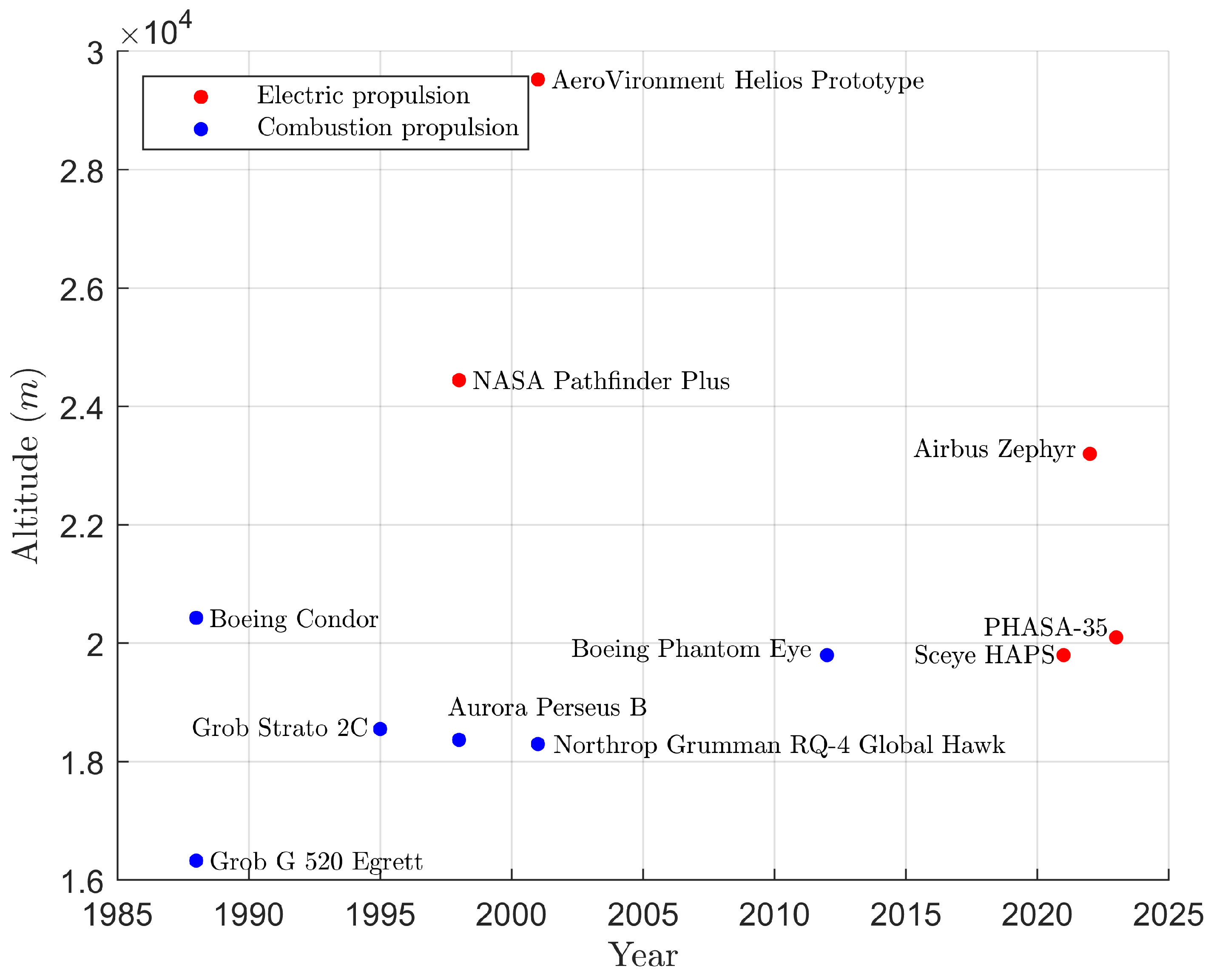
Figure 2.
Endurance performances of some of the main HAPS developed in the last 40 years, that have successfully flown at least once [2,17,18,19,20,21,22,23,24,25,26]. The year corresponds to when each endurance performance was achieved or have the capability to be achieved.
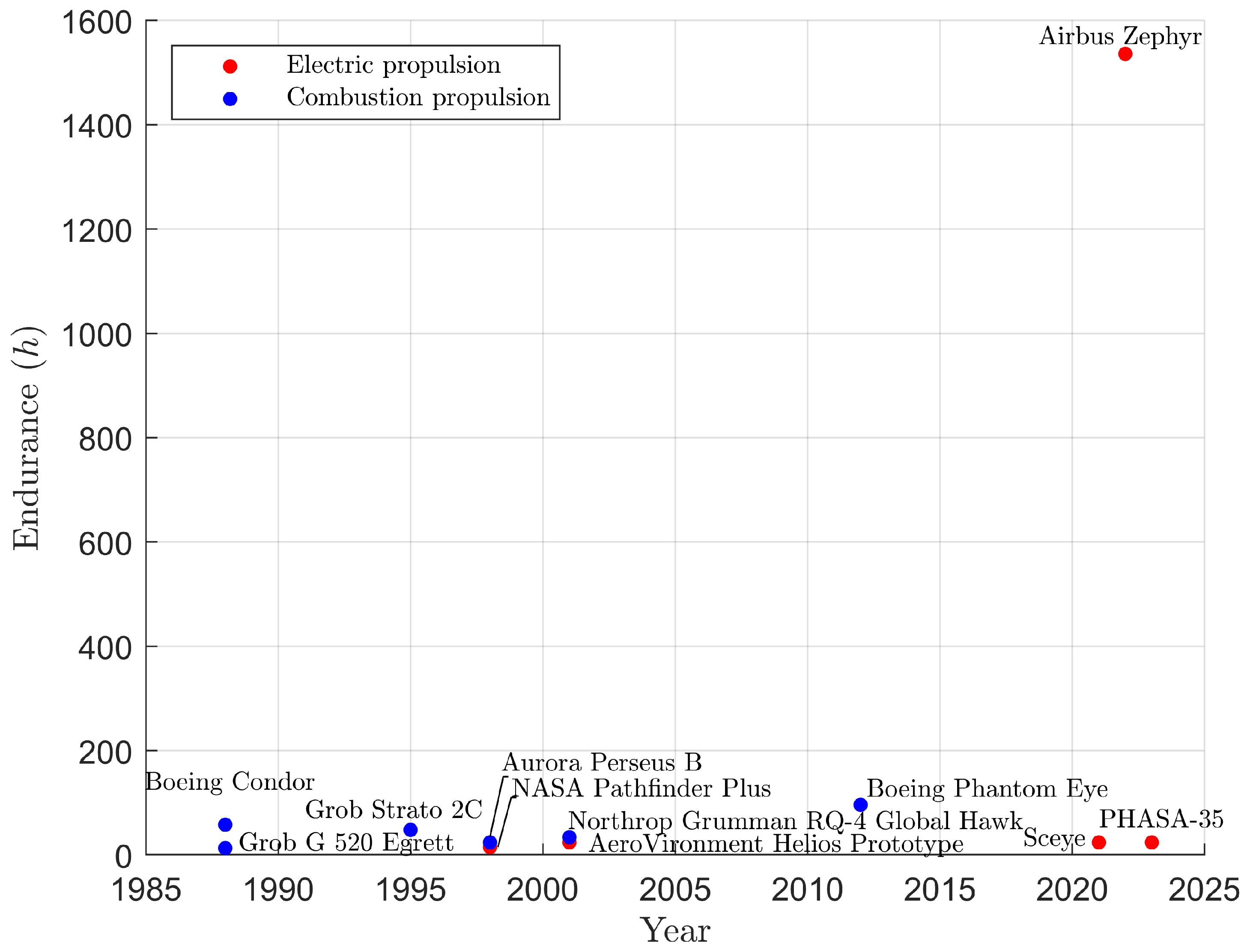
Figure 3.
Pathfinder propellers [46].
Figure 3.
Pathfinder propellers [46].
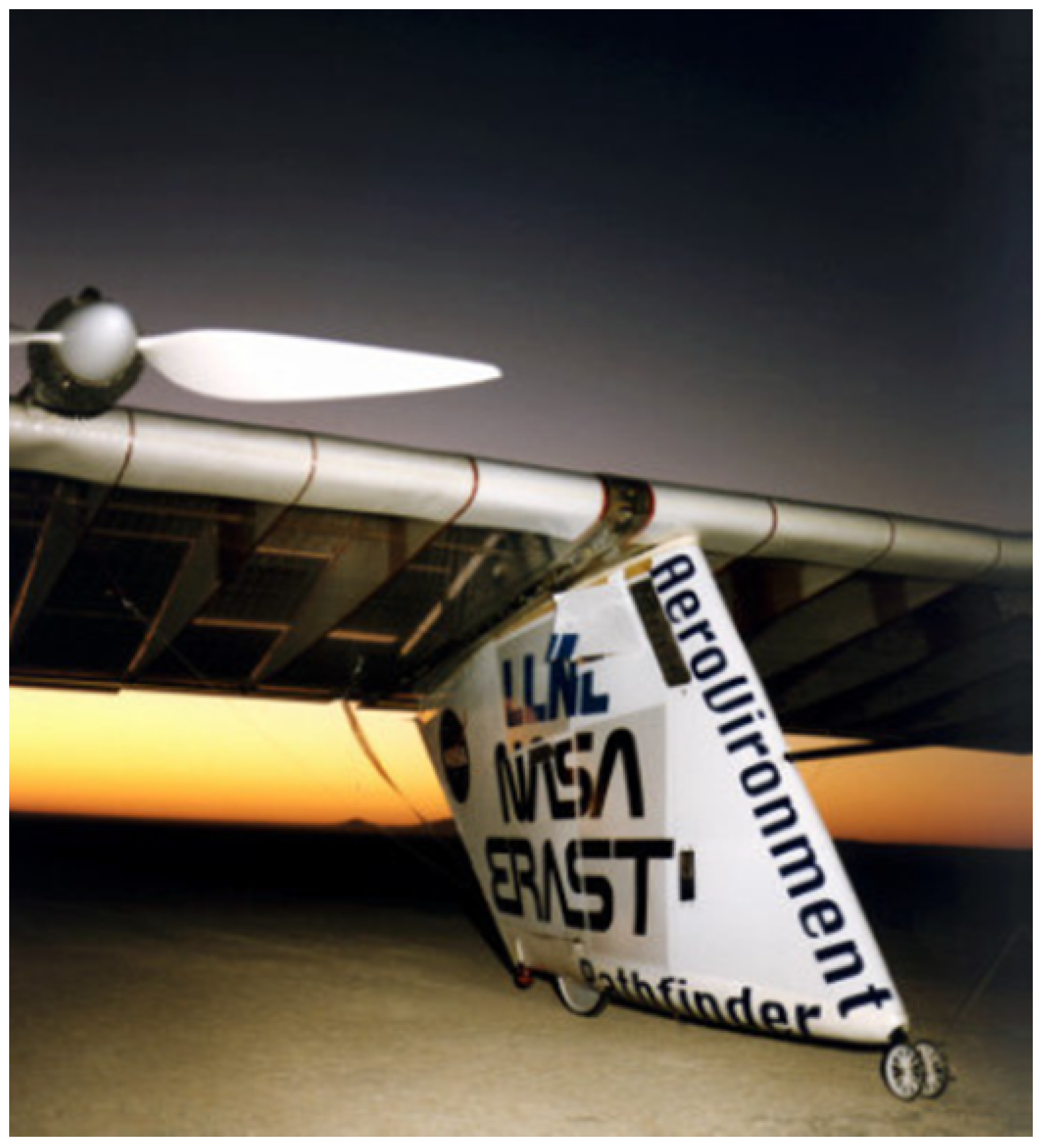
Figure 4.
Strato 2C propellers [46].
Figure 4.
Strato 2C propellers [46].
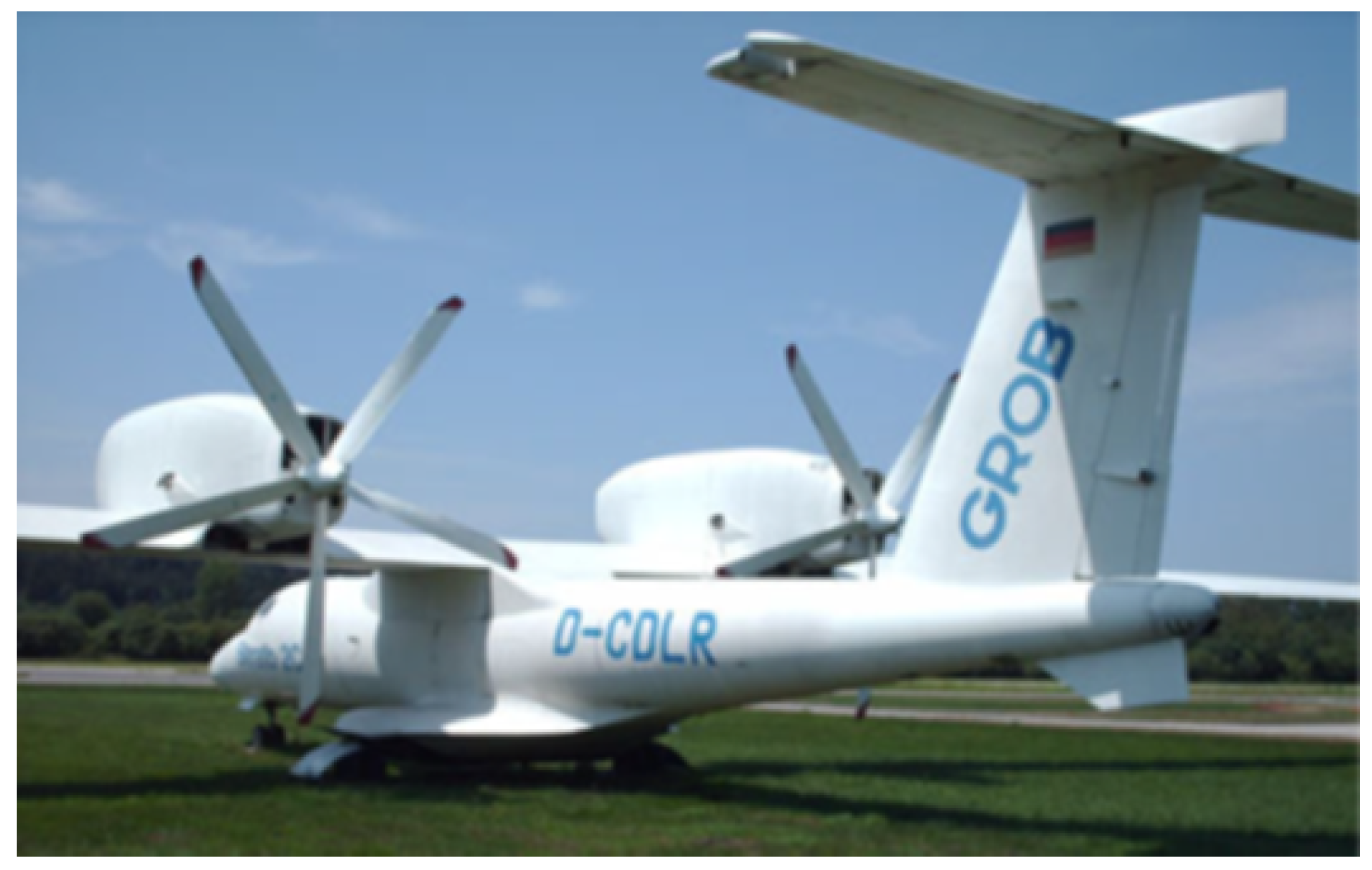
Figure 5.
UAV Perseus B propeller [46].
Figure 5.
UAV Perseus B propeller [46].
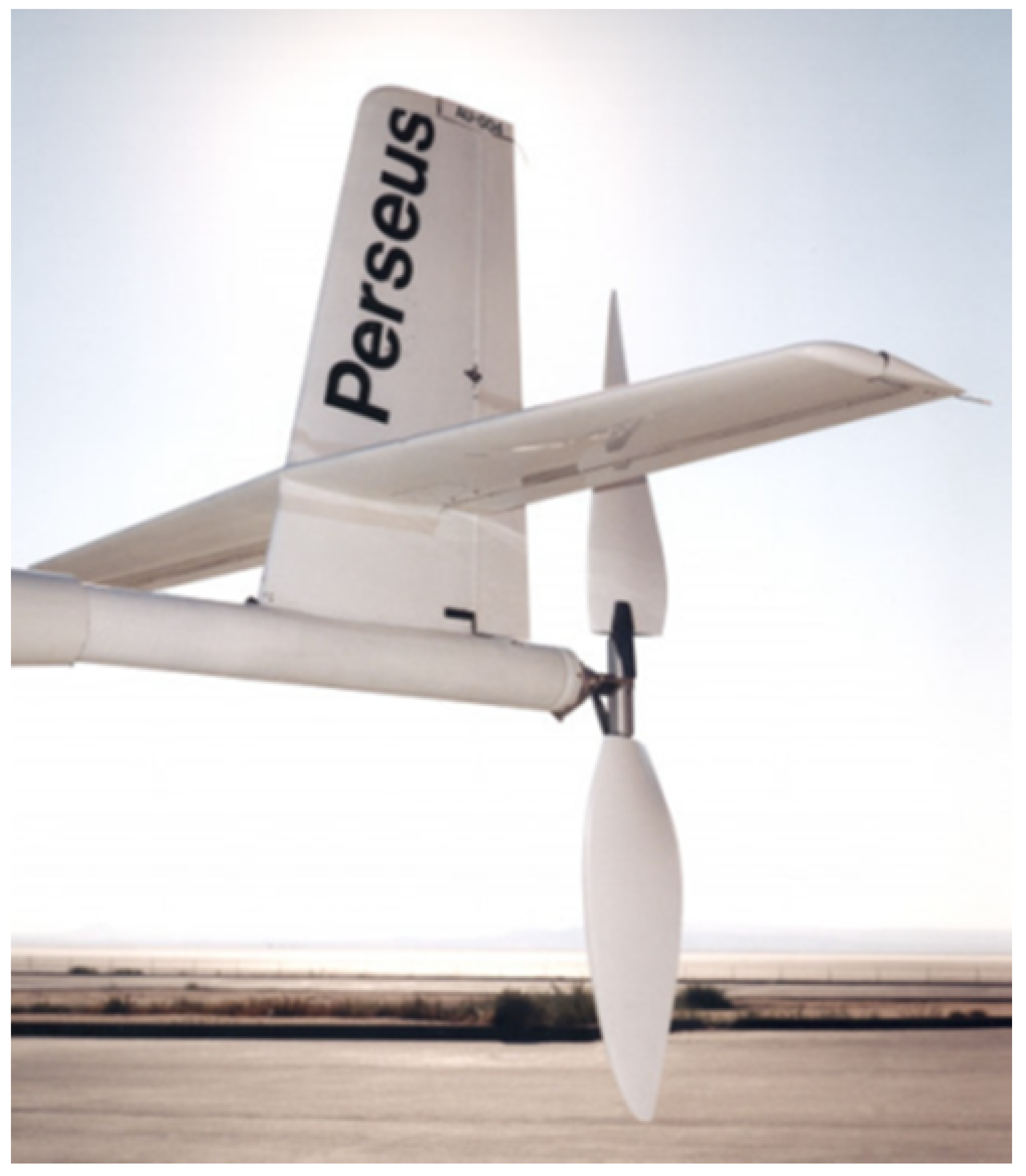
Figure 6.
UAV Perseus B propeller [46].
Figure 6.
UAV Perseus B propeller [46].
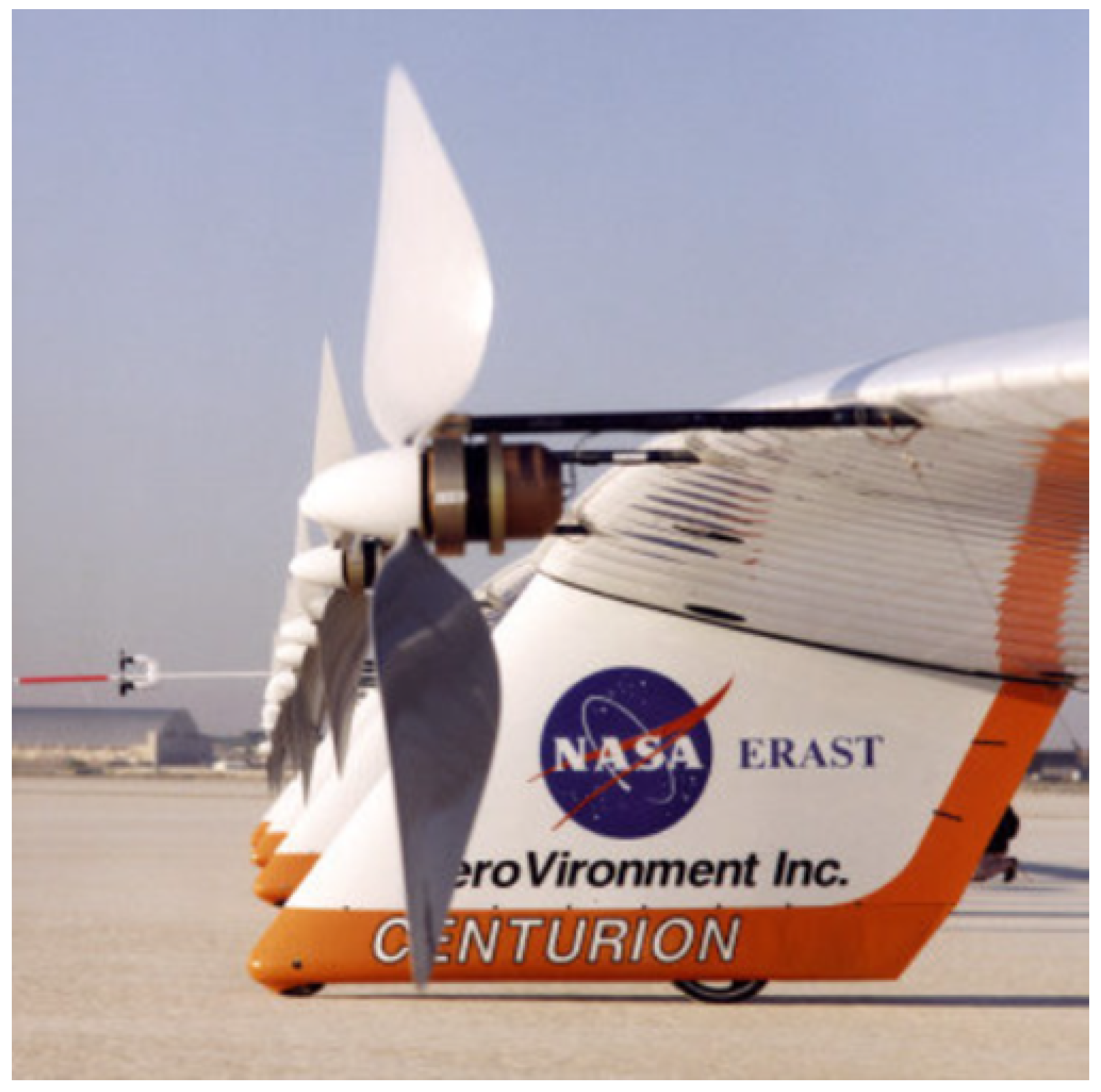
Figure 7.
Velocity, angle and force diagram.
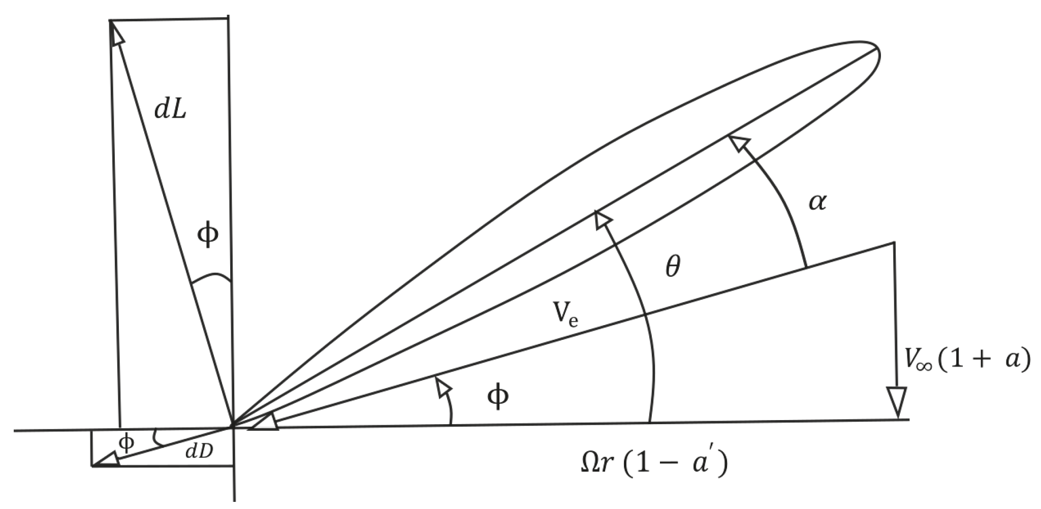
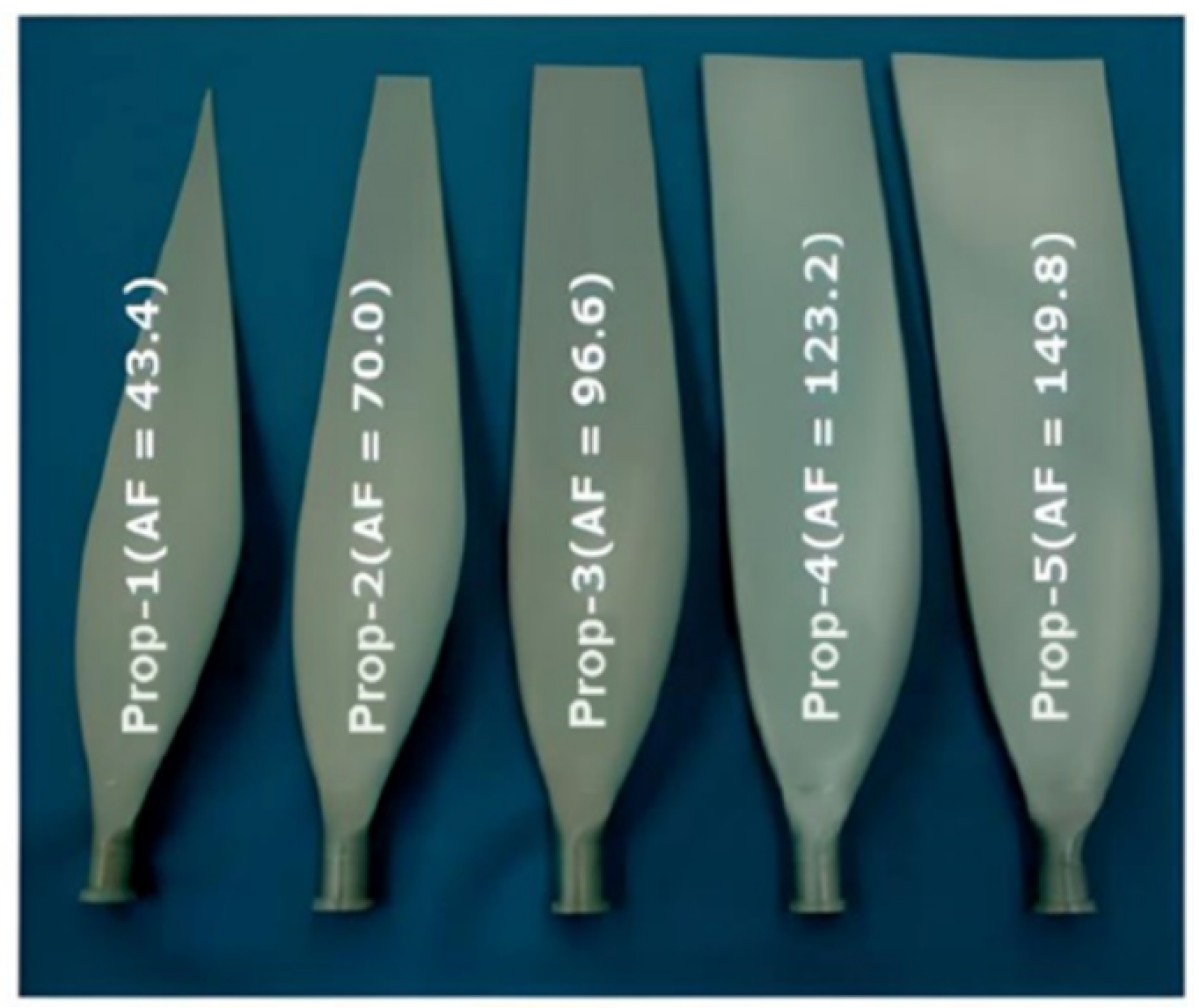
Figure 9.
CP as a function of J at various AF ratio and a constant pitch angle of [114].
Figure 9.
CP as a function of J at various AF ratio and a constant pitch angle of [114].
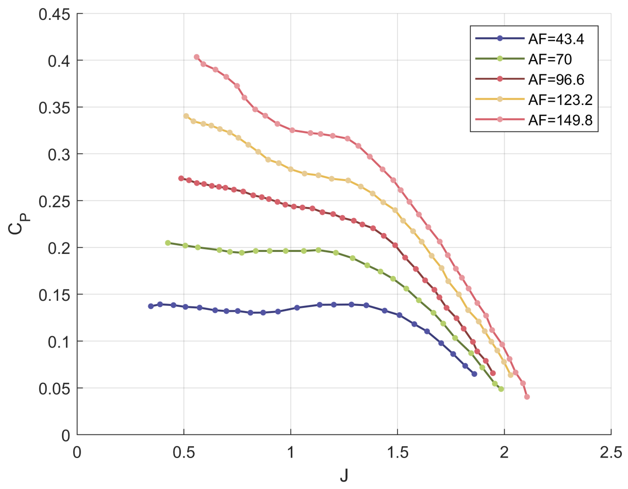
Figure 10.
Characteristic of different propeller designed ad for different HAA operation [114,115,116], in terms of power coefficient at maximum efficiency for different velocity value.
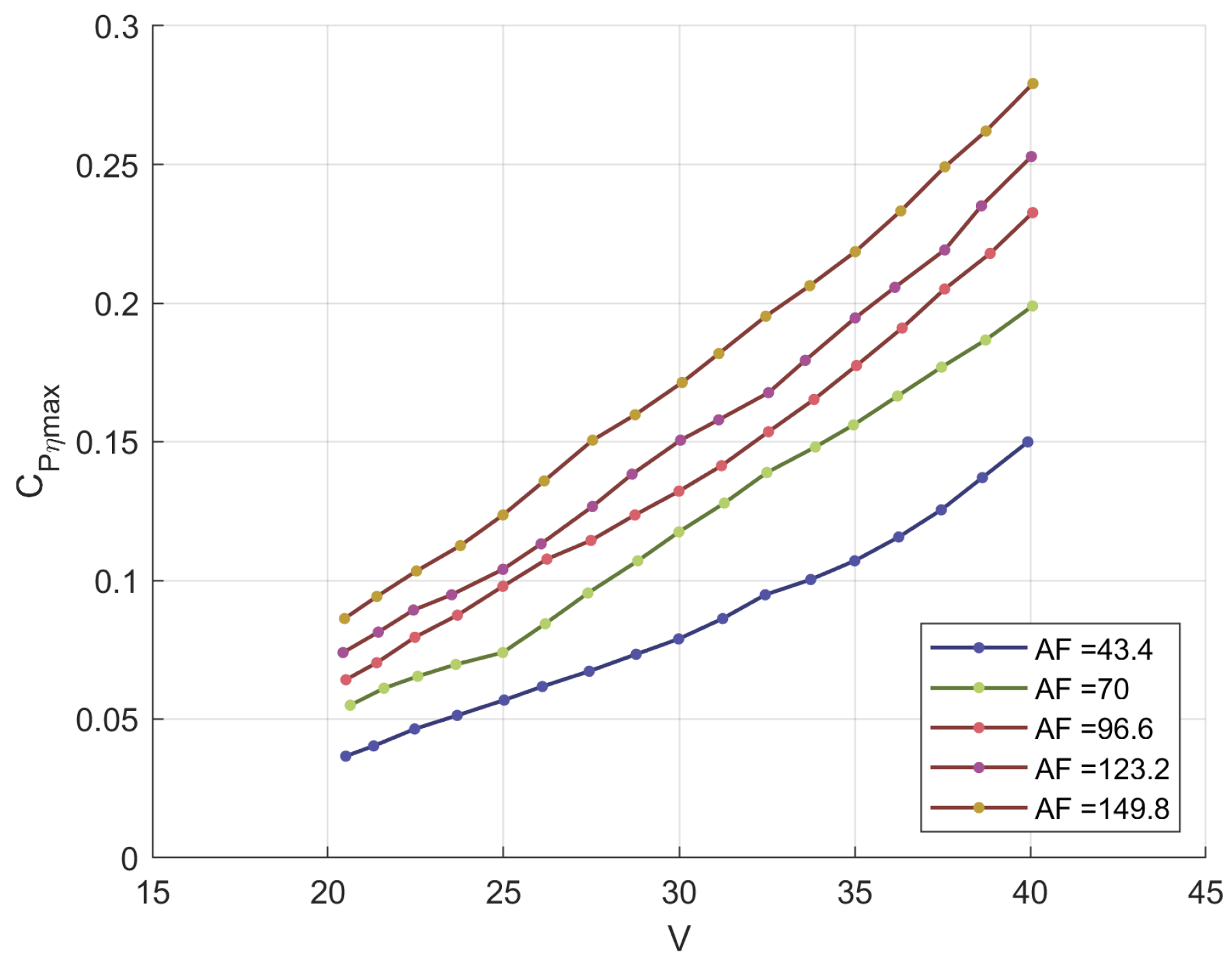
Figure 11.
Characteristic of different propeller designed ad for different HAA operation [114,115,116], in terms of Maximum efficiency curves at different advance ratio value.
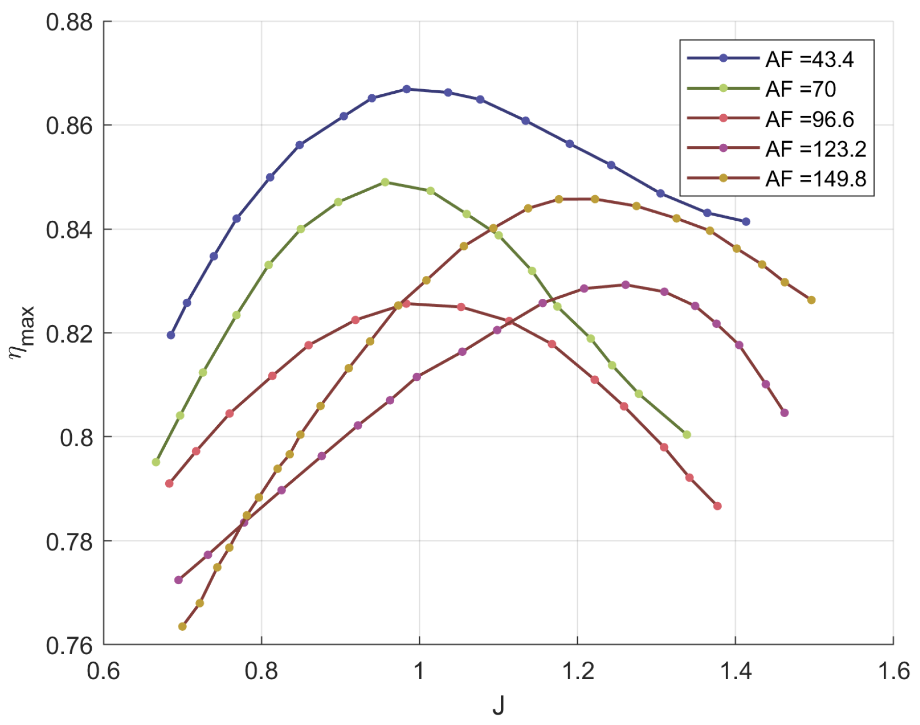
Figure 12.
Diagram of angles and speeds on the blade element considering the induced angle .
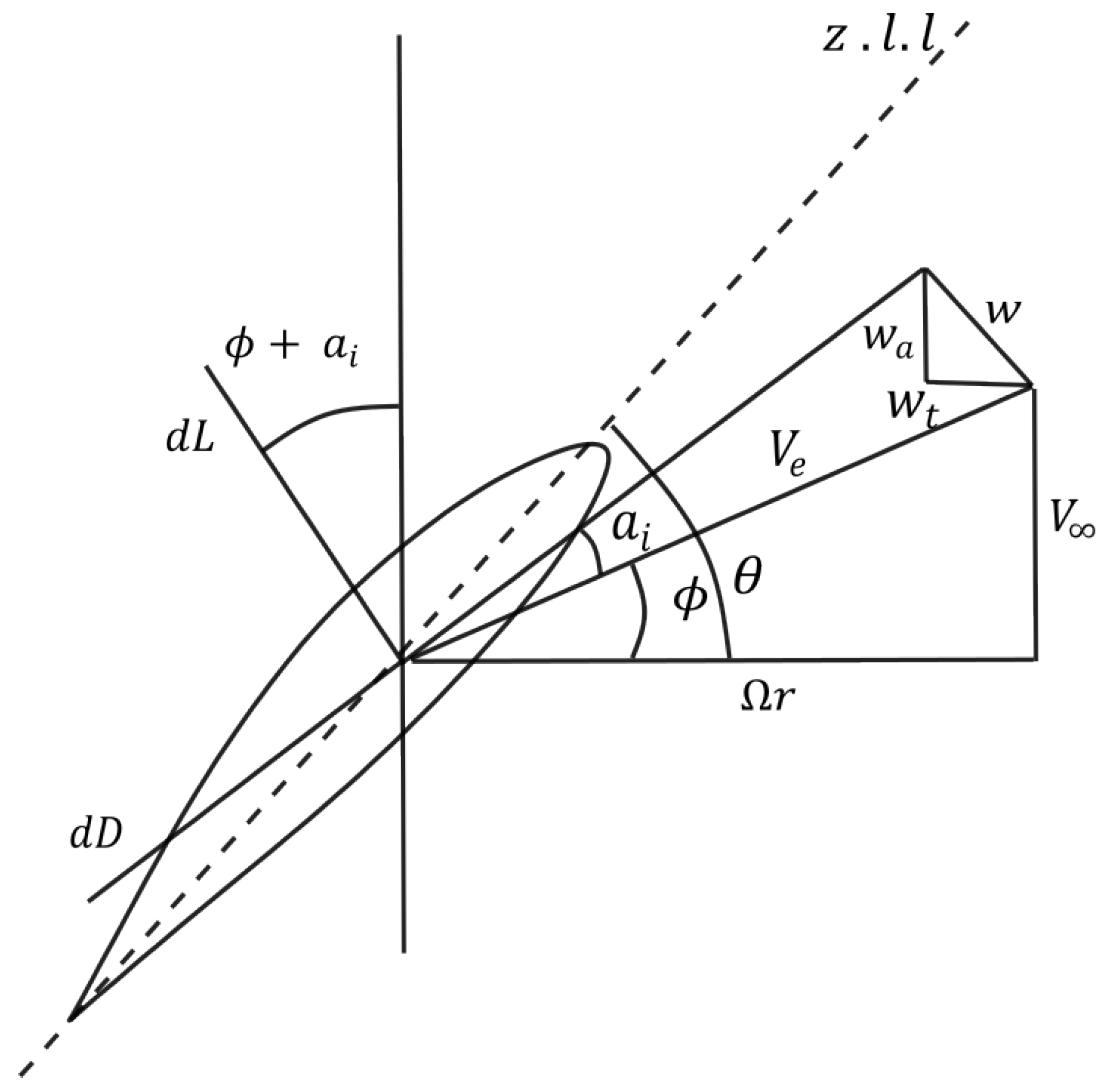
Figure 13.
Optimal design created using the optimization algorithm presented in [85]. Variation of the maximum propeller efficiency in function of J.
Figure 13.
Optimal design created using the optimization algorithm presented in [85]. Variation of the maximum propeller efficiency in function of J.
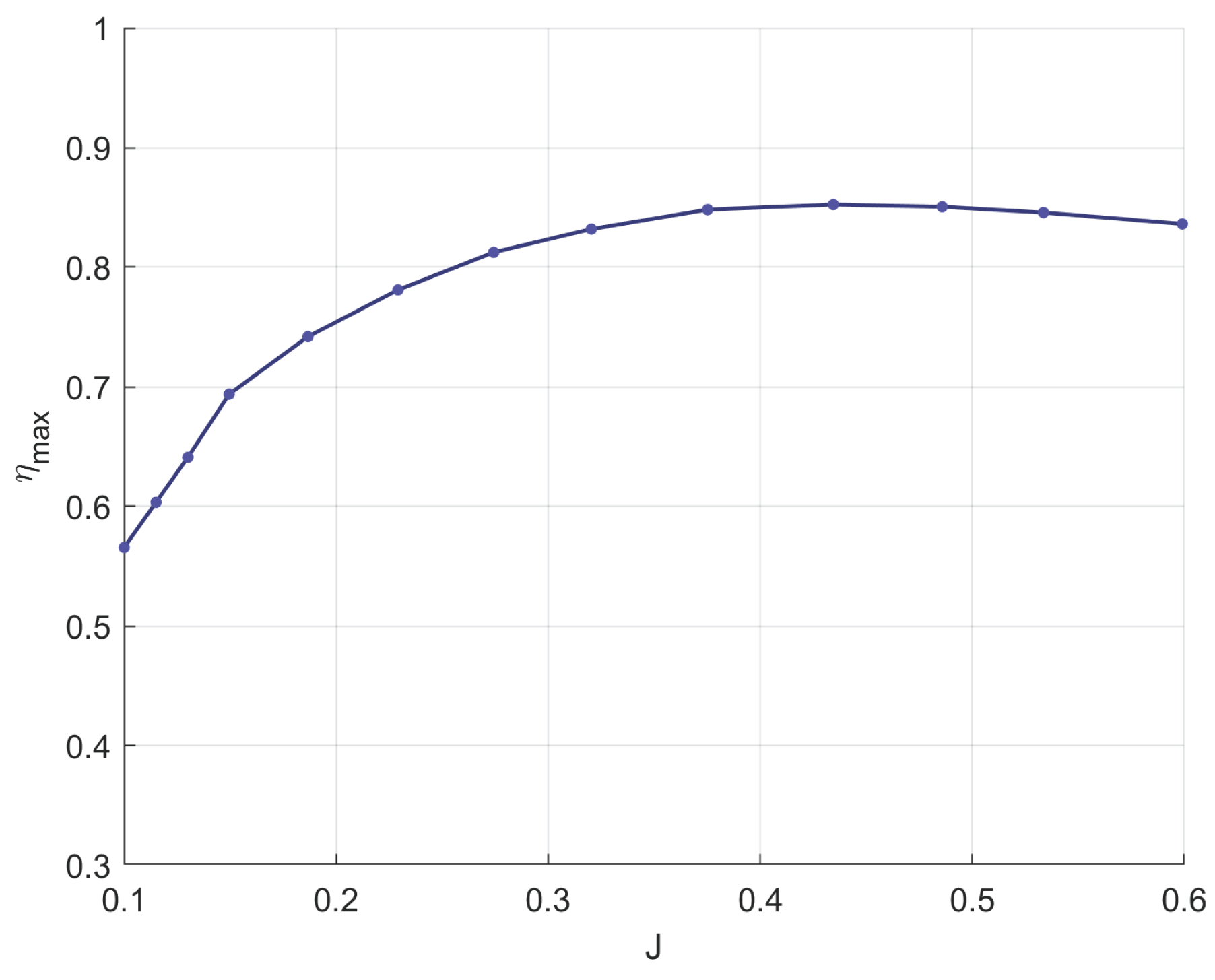
Figure 14.
(a) Comparison between the efficiency curve of a propeller, evaluated with low-fidelity and high-fidelity methods; (b) Zoomed-in view of the efficiency trends near the design point. The dashed line refers to the design point (V = 77.6 m/s, h = 16 km, RPM =1960, Nb =4, D= 1.9m).
Figure 14.
(a) Comparison between the efficiency curve of a propeller, evaluated with low-fidelity and high-fidelity methods; (b) Zoomed-in view of the efficiency trends near the design point. The dashed line refers to the design point (V = 77.6 m/s, h = 16 km, RPM =1960, Nb =4, D= 1.9m).
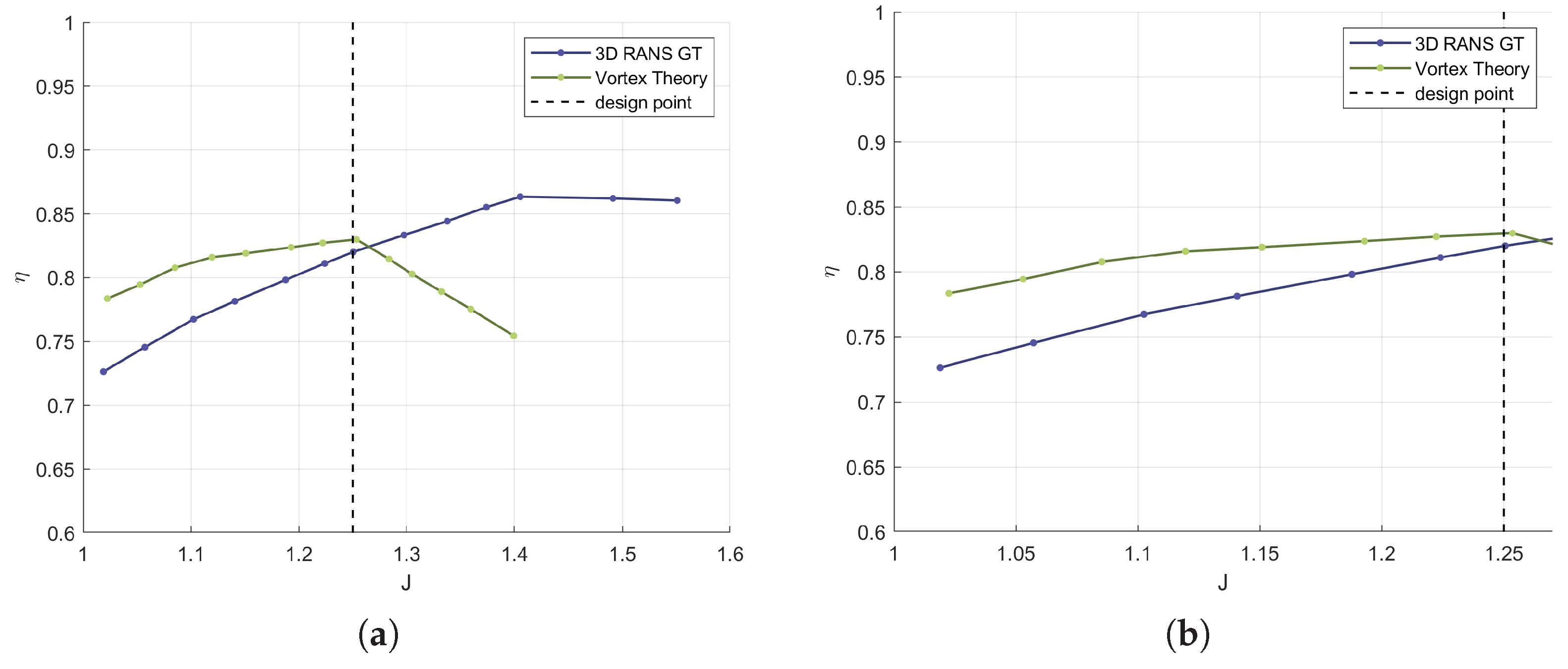
Figure 15.
Comparison of the efficiency curves of the optimized propellers with and without the Gurney flap, along with their respective design points (D =2, Nb =2, V= 32 m/s, h=20km RPM =978-948) [45] .
Figure 15.
Comparison of the efficiency curves of the optimized propellers with and without the Gurney flap, along with their respective design points (D =2, Nb =2, V= 32 m/s, h=20km RPM =978-948) [45] .
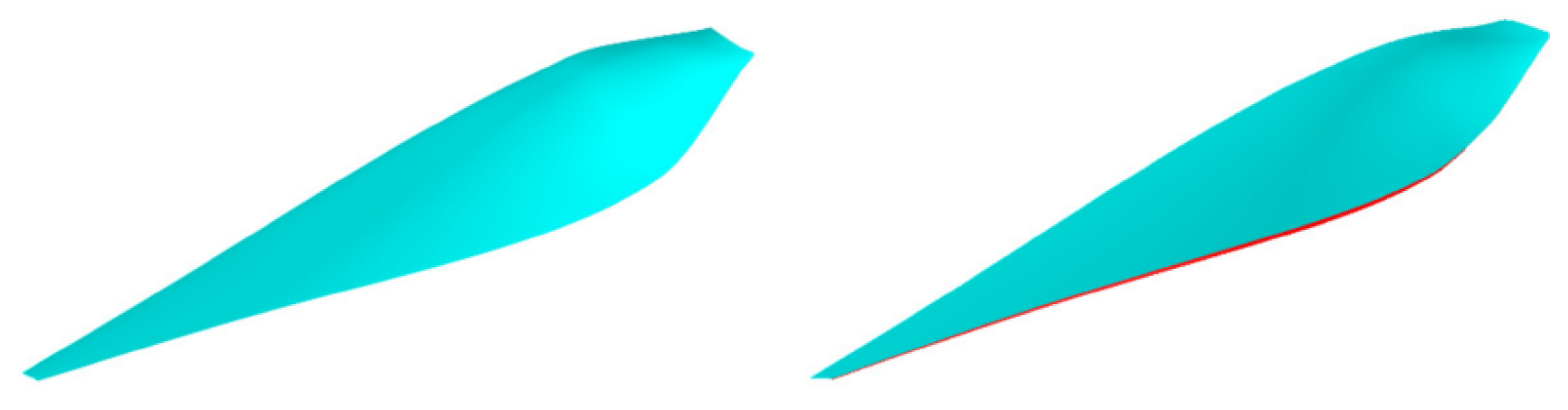
Figure 16.
Optimal design created using the optimization algorithm presented in [85]. Variation of the maximum propeller efficiency in function of J.
Figure 16.
Optimal design created using the optimization algorithm presented in [85]. Variation of the maximum propeller efficiency in function of J.
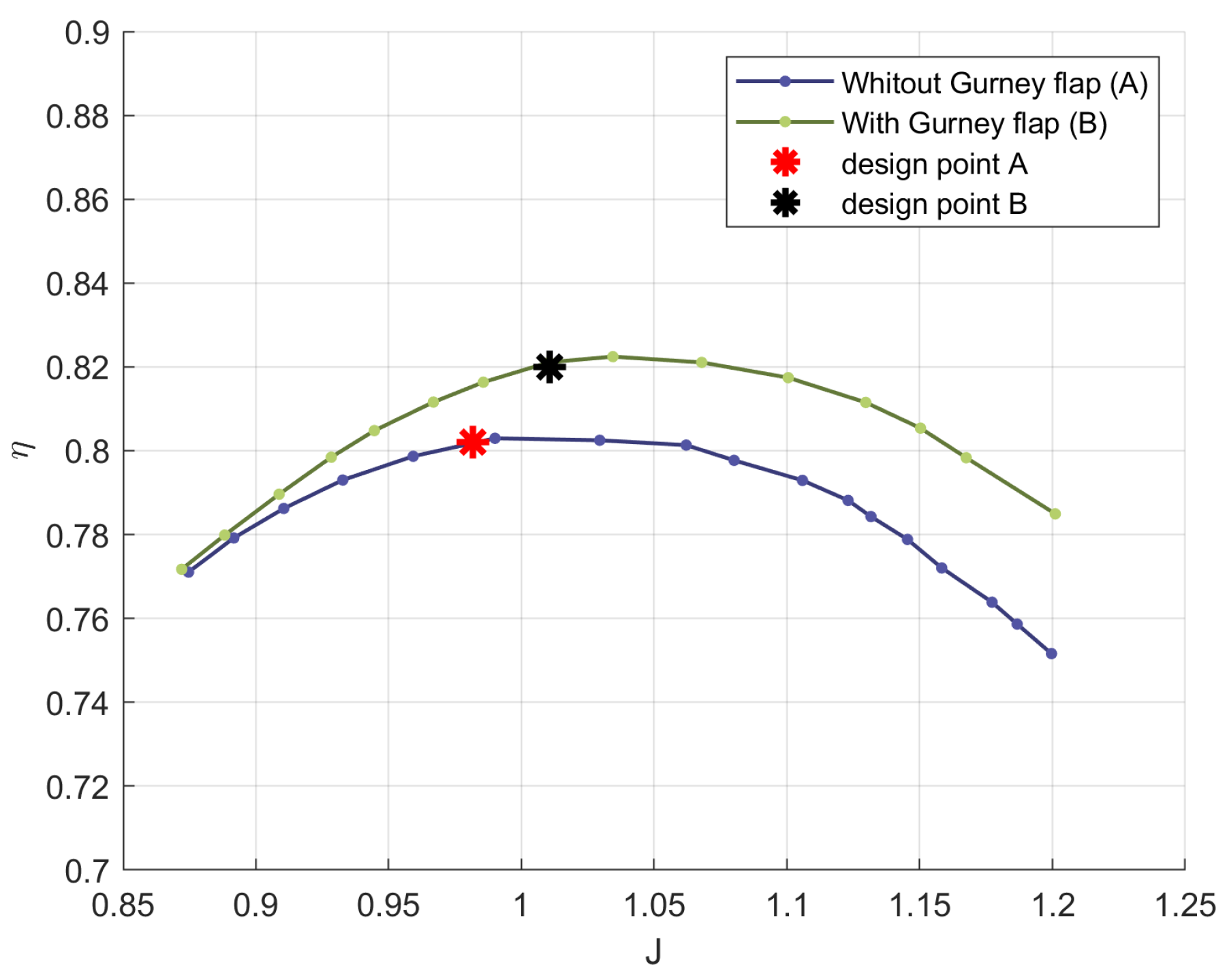
Figure 17.
Propeller as the output of the optimization process, in [149].
Figure 17.
Propeller as the output of the optimization process, in [149].
Figure 18.
Efficiency curves of the propeller obtained from the optimization process described in [149]. The dashed line refers to the design point (V =55 m/s h =16, 20 km, D =3, Nb =3, RPM = 916 RPM).
Figure 18.
Efficiency curves of the propeller obtained from the optimization process described in [149]. The dashed line refers to the design point (V =55 m/s h =16, 20 km, D =3, Nb =3, RPM = 916 RPM).
Figure 19.
Efficiency curve for the propeller designed using BEMT theory and the MFNN optimization method [96]. The dashed line refers to the design point (V = 28 m/s, RPM =1500, Nb =2, D= 1.4m).
Figure 19.
Efficiency curve for the propeller designed using BEMT theory and the MFNN optimization method [96]. The dashed line refers to the design point (V = 28 m/s, RPM =1500, Nb =2, D= 1.4m).

Table 1.
Comparison of aircraft nominal thrust and propeller diameter from various high-altitude UAV platforms.
Table 1.
Comparison of aircraft nominal thrust and propeller diameter from various high-altitude UAV platforms.
| Year | Aircraft Name | Nominal Thrust [N] | Propeller Diameter [m] |
|---|---|---|---|
| 1987 | Egrett [48,49] | 2773 | 3.04 |
| 1988 | Condor [26] | 1129 | 4.90 |
| 1993 | Pathfinder [26,46] | 23 | 2.01 |
| 1994 | Perseus [20] | 388 | 4.40 |
| 1995 | Strato2C [46,47] | 2500 | 6.00 |
| 1996 | Theseus [51] | 409 | 2.74 |
Table 2.
Characteristics of different propellers designed for various HAA operations [114,115,116,117,118,119,120] [112-118].
| Propeller | AF | D (m) | ||
|---|---|---|---|---|
| Propeller 1 | 43.4 | 0.85 | 2 | 0.87 |
| Propeller 2 | 70.0 | 0.85 | 2 | 0.85 |
| Propeller 3 | 96.6 | 0.85 | 2 | 0.83 |
| Propeller 4 | 123.2 | 0.85 | 2 | 0.83 |
| Propeller 5 | 149.8 | 0.85 | 2 | 0.85 |
Table 3.
Overview of the techniques, methodologies, and design models developed over the years for high-altitude platforms propellers and the maximum efficiency values achieved [149].
Table 3.
Overview of the techniques, methodologies, and design models developed over the years for high-altitude platforms propellers and the maximum efficiency values achieved [149].
| References | Maximum Efficiency [%] | Optimization Technique and Design Method | Model Used in Optimization |
|---|---|---|---|
| Wu et al. [96], 2024 | 87.1 | Multi-Fidelity Neural Network (MFNN)-based optimization | 3D RANS / BEMT |
| Mourousias et al. [149], 2024 | 86 | Multi-fidelity multi-objective Bayesian optimization | 3D RANS / Vortex Theory |
| Mourousias et al. [98], 2023 | 85 | Multi-fidelity Bayesian optimization | 3D RANS / Vortex Theory |
| Gutiérrez et al. [85], 2020 | 85 | Based on Wald design method [150] | BEMT |
| Mourousias et al. [144], 2022 | 84.2 | Bayesian optimization | 3D RANS |
| Marinus et al. [69], 2020 | 82.3 | Genetic algorithm (PSO) | Vortex Theory |
| Yao et al. [45], 2022 | 82 | Multi-level: Level 1 Betz method, Level 2 Genetic algorithm, Level 3 Genetic algorithm | 2D RANS / 3D RANS |
| Xu et al. [143], 2019 | 81.84 | Bayesian optimization | 3D RANS |
| Yang et al. [95], 2023 | 79.29 | Multi-level: Level 1 discrete adjoint, Level 2 parametric perturbation, Level 3 flow pattern reconstruction | 2D RANS / 3D RANS / BEMT |
| Tang et al. [129], 2019 | 78.07 (VLM), 65.2 (CFD) | Based on Kerwin’s design method [151] with VLM for contra-rotating propellers | VLM |
| Jiao et al. [86], 2018 | 75 (calculated), 70.5 (experimental scale model) | Genetic algorithm (NSGA-II) | Vortex Theory |
| Zheng et al. [70], 2017 | 73.48 (VLM), 66 (CFD) | Based on Coney’s design method [152] with VLM | VLM |
| Morgado et al. [52], 2015 | 73.2 | Based on Adkins-Liebeck design method | BEMT |
| Park et al. [128], 2018 | 65.4 | Multi-level: Level 1 inverse design based on Adkins and Liebeck, Level 2 RSM and desirability function | BEMT |
Table 4.
Percentage performance differences of a variable-pitch propeller compared to a fixed-pitch propeller at various altitudes [143].
Table 4.
Percentage performance differences of a variable-pitch propeller compared to a fixed-pitch propeller at various altitudes [143].
| Altitude (km) | Wind speed (m/s) | RPM | Shaft Power | Max Thrust | Efficiency |
|---|---|---|---|---|---|
| 20 | 25 | +43.54% | +42.35% | +36.47% | -4.06% |
| 15 | 15 | +112.17% | +112.11% | +75.06% | -17.48% |
| 10 | 10 | +139.89% | +140.66% | +83.14% | -23.85% |
| 5 | 8 | +141.37% | +141.38% | +79.46% | -29.19% |
| 0 | 6 | +156.81% | +159.09% | +78.85% | -30.86% |
Disclaimer/Publisher’s Note: The statements, opinions and data contained in all publications are solely those of the individual author(s) and contributor(s) and not of MDPI and/or the editor(s). MDPI and/or the editor(s) disclaim responsibility for any injury to people or property resulting from any ideas, methods, instructions or products referred to in the content. |
© 2025 by the authors. Licensee MDPI, Basel, Switzerland. This article is an open access article distributed under the terms and conditions of the Creative Commons Attribution (CC BY) license (http://creativecommons.org/licenses/by/4.0/).
Copyright: This open access article is published under a Creative Commons CC BY 4.0 license, which permit the free download, distribution, and reuse, provided that the author and preprint are cited in any reuse.


