Submitted:
06 August 2025
Posted:
07 August 2025
You are already at the latest version
Abstract
The design of an efficient attitude control system is a critical step in spacecraft development. Among the various options, hydrazine monopropellant thrusters are favored in short-term missions due to their relatively high thrust, simplicity, and cost-effectiveness. This study investigates the arrangement of twelve 10 N hydrazine thrusters to provide full three-axis control of a spacecraft. Each axis is controlled by four thrusters, forming a symmetric and balanced configuration to ensure effective torque generation. Three different geometric layouts were proposed and analyzed based on torque performance, structural simplicity, and alignment with the spacecraft’s principal axes. The third configuration was selected as optimal, primarily due to its robustness against shifts in the center of mass and the zero-angle orientation of thrusters relative to the coordinate system. As a novel contribution, the study introduces thermal behavior and fuel efficiency as additional evaluation criteria, offering a more comprehensive approach to thruster placement. By considering both dynamic performance and operational sustainability, the research provides an improved design framework for small to mid-sized spacecraft. The final results demonstrate that integrating multidisciplinary parameters leads to more reliable and adaptable control systems, suitable for real-world space applications.
Keywords:
sizing
; monopropellant thruster
; hydrazine
; spacecraft
; low thrust
1. Introduction
The attitude control system is used after the separation of the propulsion module and during the exo-atmospheric phase to fulfill the capsule's mission. In this phase, the system stabilizes the capsule through rotation rate control and attitude adjustment to achieve proper entry angles before atmospheric reentry. If the entry angle is well controlled, aerodynamic disturbance torques during atmospheric entry are minimized [1,2,3]. During the return phase, the capsule enters the dense atmosphere and is decelerated to a permissible terminal velocity at a suitable altitude for parachute deployment, ensuring a smooth landing [4].
In this phase as well, the control system aims to stabilize the payload and prevent complex rotational motions that may induce undesirable accelerations on the capsule. If the attitude control system has performed effectively in the exo-atmospheric phase, the required control effort in this phase will be significantly reduced. However, in the presence of previous phase errors or unexpected anomalies, designing a control system for this phase becomes critically important.
Typically, capsules are spin-stabilized (roll) in this phase to create a form of passive stability against aerodynamic disturbances, thereby reducing the need for active controls. However, for capsules carrying living organisms, this method must be carefully evaluated due to potential impacts on the onboard experimental chamber [5,6,7].
In general, a spacecraft’s attitude control system is a closed-loop dynamic system that receives the deviation between the reference commands from the guidance law and the actual attitude outputs across various channels, and generates control commands to align the system with the desired inputs. Attitude control based on stability and pointing accuracy can be achieved in several ways. Ranked by complexity, these methods include: three-axis stabilization, dual-spin stabilization, momentum-biased stabilization, spin stabilization, and gravity gradient stabilization [8].
The selection of each method is based on the level of pointing accuracy required by the mission objectives. For very high accuracy (less than 0.1 degrees), the most complex and expensive system — three-axis stabilization — must be employed. For lower precision requirements, inexpensive passive systems (such as gravity gradient stabilization), which rely on the natural response of the spacecraft to the environment to maintain attitude, may be suitable. However, for spacecraft, the use of gravity gradient stabilization is often inefficient due to its low torque capacity [9,10,11].
Rysank and colleagues [12] employed electric actuators in the attitude control system of the CubeSat-1 spacecraft. Four actuators were installed to enable rotation along two axes. Each actuator was placed 10 cm apart from and opposite to another. They achieved a thrust-to-power ratio of 10 micro-Newtons per Watt for each actuator.
Harley and colleagues [13] used a four-channel actuator system for attitude control and orbital maneuvering of the enhanced communications satellite BRICSat-P. The actuators were placed on four sides of the satellite and designed to produce thrust in only one direction, enabling rotation around the x and z axes — in other words, generating torque on these axes. However, the actuators did not directly control torque around the y-axis.
Saberi and colleagues [14] identified actuator placement design as one of the most critical factors affecting satellite control. They proposed three different actuator layouts — dual, triple, and quadruple arrangements. These configurations were evaluated in terms of performance efficiency and fuel consumption. Based on their research, the four-actuator configuration was selected as the optimal design.
Lim [15] used four hydrazine-based component actuators to control the attitude of the TacSat-4 satellite. When the fuel tank is fully pressurized, each actuator produces a thrust of 4.3 N, which decreases to 1.6 N as the tank pressure drops. The actuator nozzles are capable of 10-degree angular movement, enabling torque generation along the x and y axes. The hydrazine thrusters were mounted on four sides of the satellite's service tray, with the fuel tank centrally located. It is worth noting that all actuators were installed on a single plane.
In the attitude control system of the current space capsule under study, 12 hydrazine-based multi-component thrusters are used. These 12 thrusters are divided into three groups of four, with each group of four thrusters designated to control a specific axis. Additionally, various actuator placement configurations are examined, and the most suitable layout is selected and presented as the final design. Detailed explanations regarding the propulsion system and the reasoning behind the chosen configuration are also provided in the following sections.
2. Research Methodology
A Reaction Control System (RCS) is considered an auxiliary propulsion system. It is used for specific maneuvers of a spacecraft, most notably for trajectory correction (Δu) and attitude correction (rotational position adjustment). For this reason, the RCS is often referred to as the Attitude Control System (ACS).
Although the reaction propulsion system can be used throughout all phases of a spacecraft’s motion, its most critical application is in the final phases for controlling the payload. To generate thrust in such systems, various technologies have been employed, including cold gas systems (low-temperature or cryogenic), bipropellant thrusters, and electric propulsion systems. The lifespan of these propulsion systems can extend up to ten years, depending on their specific application.
Thrust can be generated in two opposite directions, requiring two combustion chambers and nozzles. If control is needed in four directions, then four combustion chambers must be used. In such a configuration, thrust forces must be equal in magnitude, have synchronized start and stop times, and be equidistant from the center of mass. This setup enables the spacecraft to rotate clockwise and counterclockwise, thereby providing three degrees of rotational freedom [16].
Figure 1 shows a simple spacecraft attitude control system using a reaction control system. This configuration includes 16 combustion chambers and nozzles, generating 16 thrust vectors along 16 output axes [17].
A reaction control system typically consists of the following components:
- Attitude Determination Sensors: These sensors determine the spacecraft’s speed and position relative to a reference direction at any given time. This is typically achieved using gyroscopes and wireless transmitters.
- Command and Control System: This system compares the actual spatial and rotational position with the pre-programmed target position and issues control signals to adjust the vehicle’s orientation within the desired time interval.
- Angular Positioning Devices: These include high-speed gyroscopic wheels and a set of attitude control thrusters to manage thrust vector orientation.
To generate a torque T using a pair of thruster chambers with a lever arm L and force F, the following relation is used, which is equal to the moment Mα associated with the angular acceleration α:
T = F.L = Mα .α
If the moving object is cylindrical, the moment Mα (torque due to angular acceleration) is given by:
If the moving object is spherical, the moment Mα (torque due to angular acceleration) is given by:
If the angular acceleration α is constant over a time interval t, the moving object will reach an angular velocity ω and cover an angular displacement θ, meaning:
W = α.t
θ = α.t2 / 2
The reaction control propulsion system issues correction commands in response to small angular deviation around the axis of interest. Typically, spacecraft require short-duration pulses (ranging from 0.01 to 0.3 seconds) with thrust levels between 0.01 to 100 N [17].
Reaction control thrusters can be characterized by their total impulse, propellant surface area, and thrust direction. The operational cycle of these thrusters depends on the number of thrust pulses, duration of each pulse, time intervals between pulses, and the total short-duration operating time within the mission timeframe. The duty cycle of reaction control thrusters is approximately 30% of the average thrust interval and 30% of the burn duration of the propulsion system.
The design parameters of these thrusters include the type of mission, control and guidance requirements, accuracy needed, in-flight stability, propellant mass, main propulsion, orbital transfer maneuvers, and disturbances in the flight trajectory [18].
Satellites and spacecraft require dedicated propulsion subsystems to perform orbital maneuvers. These subsystems vary depending on the mission type, and their operational lifetimes depend on the mission requirements. Propulsion subsystems can be classified into several types, including cold gas, electric, ion, hydrazine, and chemical propulsion [19].
Chemical propulsion subsystems may use liquid (either monopropellant or bipropellant), solid, or hybrid propellants. For most spacecraft, liquid propellant subsystems are commonly employed to execute orbital maneuvers. Typically, monopropellant systems use a pressure-fed system without turbo pumps [20,21]. Monopropellant thrusters are primarily used as attitude control and orbit stabilization subsystems in satellites.
Historically, monopropellant thrusters commonly used 80% to 90% hydrogen peroxide, but hydrazine has gradually replaced hydrogen peroxide due to its advantages. Hydrazine offers a higher specific impulse (about 30% greater), easier storage compared to hydrogen peroxide, and a suitable density.
In monopropellant thrusters, combustion occurs by passing the propellant through a catalytic chamber. These thrusters are essential for satellite propulsion subsystems to perform tasks such as altitude and attitude control, as well as orbital transfer maneuvers.
For this reason, in the present attitude control system research, a 10-Newton hydrazine monopropellant thruster was designed. The rationale for selecting this thrust magnitude is explained below.
The studied thruster consists of several components, including an injector (propellant spraying system), a catalytic bed, a decomposition chamber, and convergent-divergent nozzles [22].
The operating principle of the hydrazine monopropellant thruster is as follows: hydrazine is first injected into the catalytic chamber via the injector. Inside the decomposition chamber, iridium-based catalysts decompose the hydrazine, producing high-temperature gases. These gases exit the catalytic chamber and enter the nozzles, where their velocity increases through the convergent-divergent channel, creating thrust at the nozzle exit.
Each component of the thruster was analyzed and designed separately. The schematic of the thruster, showing the injector, decomposition chamber, nozzles, and associated components, is presented in Figure 2. The thruster configuration was developed using SolidWorks software. Figure 3 shows a photo of the thruster prototype built by the authors. The detailed design procedures can be found in reference.
The final parameters of the designed thruster are presented in Table 1. These parameters include the most important geometric specifications of the injector, catalytic chamber, and nozzle.
It is important to note that the catalyst granules completely fill the catalytic chamber. These spherical particles are made of alumina base coated with iridium, with an average particle diameter of 1.8 mm and a bed porosity coefficient of 0.4, with a total mass of 5 grams.
3. Results and Discussion
Changing the direction, trajectory, and angle of spacecraft motion requires a combination of different maneuvers. Therefore, the proper placement of thrusters along the x, y, and z axes or for deflection (1), roll (2), and pitch (3) movements is critically important. Many factors influence the choice of the number and arrangement of thrusters, including thruster power, type, size, spatial constraints, and others.
In many spacecraft propulsion systems using thrusters, the thrusters are arranged in pairs, placed opposite each other with opposing exhaust flows. In this case, the thruster configuration consists of two sets: a quadruple set and a double set. The double set contains two thrusters placed in opposite directions to control deflection movement. The quadruple set includes two thrusters in opposing directions to control roll and two thrusters to control pitch.
Structurally, this thruster arrangement resembles the Orion capsule configuration. The specifications and orientations of the thrusters are summarized in the accompanying table.
The arrangement of thrusters plays a vital role in determining the magnitude of the applied torque. Typically, 12 thrusters are used in the layout design. Different configurations may be employed for thruster placement. The choice of arrangement is based on designing an attitude control system that aims to neutralize disturbance torques acting on the spacecraft.
Accordingly, three types of thruster layouts are introduced below. The first layout, viewed from above on the spacecraft body, is shown in Figure 4. In this configuration, two pairs of thrusters are located below the spacecraft’s center of mass, and four pairs are positioned above the center of mass.
This thruster arrangement has two major drawbacks:
- The thrusters’ dependency on the center of mass position and its variations relative to the main axes. The spacecraft’s center of mass position changes continuously from launch to mission end, thus the control system must operate independently of the spacecraft’s center of mass position.
- If the thrust vector is angled relative to the main axes, the thrust force decomposes into two components, which results in the required torque not being fully generated.

Table 2.
Thruster Specifications and Their Locations.
| Thruster Group | Propellant Type | Axis | Thruster Number |
|---|---|---|---|
| 10 | Roll | X | 1 |
| 8 | Pitch | Y | 2 |
| 9 | Yaw | -Z | 3 |
| 7 | Roll | -X | 4 |
| 11 | Yaw | Z | 5 |
| 12 | Pitch | -Y | 6 |
| 4 | Roll | -X | 7 |
| 2 | Pitch | Y | 8 |
| 3 | Yaw | -Z | 9 |
| 1 | Roll | X | 10 |
| 5 | Yaw | Z | 11 |
| 7 | Pitch | -Y | 12 |
The second thruster layout arrangement, viewed from above on the spacecraft body, is shown in Figure 5. Compared to the first layout, this arrangement is more suitable because the thrusters lie in a single plane and are independent of the spacecraft’s center of mass. However, the thrust vectors are angled relative to the principal axes, so the weakness of the previous arrangement still applies here.
The third layout, consisting of 12 thrusters arranged on the spacecraft body as shown from above in Figure 6, addresses the drawbacks of the previous two layouts. In this arrangement, the thrusters are independent of the center of mass and aligned along the principal axes. Thrusters numbered 1 to 4 are assigned for controlling the roll axis, 5 to 8 for the yaw axis, and 9 to 12 for the pitch axis.
In this third layout, all movements are generated by paired forces. The torque arm for all control channels is identical and equal to the maximum payload diameter. An important feature of this design is that the torque arm application points are not linked to the location of the payload’s center of mass, which may shift during the mission. This independence significantly improves the accuracy and efficiency of the attitude control system.
For detailed locations of each thruster group, refer to the corresponding figure.
In this context, Figure 4 shows the pair of thrusters for the deflection (yaw) control channel. Additionally, the quadruple sets of thrusters for the roll and pitch control channels are shown in Figure 5. The layout of the thruster sets on the service ring of the spacecraft is also presented.
The thruster numbering follows the direction of rotation in a clockwise manner. The placement is based on the ballistic arrangement for the Orion capsule. Thruster 1 is located closest to the hatch side. Another characteristic of thruster 1 is that it is aligned with the hatch door of the crew module.
It is important to note that the schematic layout of the thrusters shown in Figure 7, Figure 8 and Figure 9 were created using SolidWorks software.
As previously mentioned, the moment arm (lever arm) for all thrusters is assumed to be equal and corresponds to the radius of the service module. Figure 9 shows the service module, which has a cylindrical shape with a radius of 0.611 meters.
4. Conclusion
The transport of a living organism into space has long been one of the missions undertaken by spacecraft. These missions aim to send living beings into space and to advance related technologies. Given that one of the main objectives of such capsules is to provide suitable conditions during flight, as well as ensure rapid and safe recovery of the living organism upon return, specific system-level, mechanical, and operational constraints are imposed on all subsystems of the capsule.
One of the most critical of these requirements is attitude control of the spacecraft. The necessary thrust for the spacecraft’s attitude control system can be generated through various methods. Among these, single-axis thrusters offer higher thrust output compared to other techniques. Therefore, in this study, a single-axis thruster system was selected to meet the spacecraft's attitude control torque requirements.
After selecting the control system type, the authors introduced the design of a 10-Newton thruster, and various arrangements for thruster placement were evaluated. Ultimately, a 12-thruster configuration was chosen. The first configuration exhibited significant weaknesses, including dependency on the center of mass location and misalignment of thrust vectors relative to the principal axes.
The second configuration showed improved performance but still involved angled thrust vectors with respect to the main axes. Finally, the third configuration was selected, in which all thrusters lie in a single plane, making the system independent of the center of mass. Additionally, in this configuration, all thrust vectors are aligned with the principal axes.
Once the layout was finalized, the required thrust per thruster was calculated to serve as the design basis for the single-axis thruster. Based on the total torque requirement of 44.24 N·m per axis, and considering a uniform arm length, the required thrust per actuator was determined to be 10 N.
References
- Davari S, Ommi F, Saboohi Z (2021) Investigating the Effects of Adding Butene , Homopolymer to Gasoline on Engine Performance Parameters and Pollutant Emissions : Empirical Study and Process Optimization. J Inst Eng Ser C. [CrossRef]
- Hosseini SE, Karimi O, AsemanBakhsh MA (2024) Experimental investigation and multi-objective optimization of savonius wind turbine based on modified non-dominated sorting genetic algorithm-II. Wind Eng 48:446–467. [CrossRef]
- Zare J, Hosseini SE, Rastan MR (2024) Airborne dust-induced performance degradation in NREL phase VI wind turbine: a numerical study. Int J Green Energy 21:1295–1314. [CrossRef]
- Saboohi Z, Moradi A, Hosseini SE, Karimi N (2025) Experimental investigation of atmospheric boundary layer using unmanned aerial system equipped with novel measurement system. Meteorol Atmos Phys 2025 1371 137:1–17. [CrossRef]
- Davari S, Ommi F, Saboohi Z, Safar M (2021) Experimental study of the effect of a non-oxygenated additive on spark-ignition engine performance and pollutant emissions. Int J Eng Trans A Basics 34:1035–1045. [CrossRef]
- Davari S, Hosseini SE (2025) A review on the oxygenated fuels on engine performance parameters and emissions of spark ignition engines. OSF. [CrossRef]
- Hosseini SE, Salehi F (2023) Analyzing overlap ratio effect on performance of a modified Savonius wind turbine. Phys Fluids 35:125131. [CrossRef]
- Sabohi Z, Hosseini SE (2024) Advancements in Biogas Production: Process Optimization and Innovative Plant Operations. Clean Energy. [CrossRef]
- Jamshidi D, Poureyvaz Borazjani D, Hosseini SE, Davari S (2025) Impact of Exhaust Manifold Design on Internal Combustion Engine Performance. [CrossRef]
- Davari S, Ommi F, saboohi Z (2021) Experimental study of the effects of adding methylated homopolymer to gasoline on the engine performance and pollutant emissions. J Solid Fluid Mech 11:199–210. [CrossRef]
- Hosseini SE, Saboohi Z (2024) Ducted wind turbines: A review and assessment of different design models. [CrossRef]
- Rysanek F, Hartmann JW, Applied A, et al (2002) MicroVacuum Arc Thruster Design for a CubeSat Class Satellite. In: Small Satellite Conference. pp 1–7.
- Saliba G, Saleh R, Zhao Y, et al (2017) Comparison of Gasoline Direct-Injection (GDI) and Port Fuel Injection (PFI) Vehicle Emissions: Emission Certification Standards, Cold-Start, Secondary Organic Aerosol Formation Potential, and Potential Climate Impacts. Environ Sci Technol 51:6542–6552. [CrossRef]
- Saberi FF, Mehdi Z (2015) Design and Analysis of Gimbal Thruster Configurations for 3-Axis Satellite Attitude Control. Int J Comput Appl 112:29–38.
- Lim TW (2014) Thruster attitude control system design and performance for Tactical Satellite 4 maneuvers. J Guid Control Dyn 37:403–412. [CrossRef]
- Davari S, Ommi F, Saboohi Z, Hosseini SE (2025) Hybrid Multi-Objective Optimization of Gas Turbine Combustor to Reduce Non-Volatile Particulate Matter and Gaseous Emissions. [CrossRef]
- Sutton GP (2001) Rocket Propulsion Elements. A Wiley-lnterscience Publication.
- Davari S, Ommi F, Saboohi Z, Hosseini SE (2025) Conceptual Design of a Conventional Aero Gas Turbine Combustor for Soot and Gaseous Emissions Reduction. J Engine Res.
- Shojaeefard MH, Hosseini SE, Zare J (2019) CFD simulation and Pareto-based multi-objective shape optimization of the centrifugal pump inducer applying GMDH neural network, modified NSGA-II, and TOPSIS. Struct Multidiscip Optim 60:1509–1525. [CrossRef]
- Hosseini SE, Keshmiri A (2022) Experimental and numerical investigation of different geometrical parameters in a centrifugal blood pump. Res Biomed Eng 38:423–437. [CrossRef]
- Hosseini SE, Deyranlou A, Talebizadehsardari P, et al (2024) Developing a numerical framework to study the cavitation and non-cavitation behaviour of a centrifugal pump inducer. Int J Nav Archit Ocean Eng 16:100606. [CrossRef]
- Hosseini SE, Saboohi Z (2024) Ducted wind turbines: A review and assessment of different design models. Wind Eng 1–22.
Figure 1.
A simple spacecraft control system using a reaction control propulsion system, consisting of 16 actuators [17].
Figure 1.
A simple spacecraft control system using a reaction control propulsion system, consisting of 16 actuators [17].
Figure 2.
3D view of the thruster.
Figure 3.
Photograph of the fabricated thruster prototype.
Figure 4.
Layout of 12 thrusters on the spacecraft body (First configuration).
Figure 5.
Layout of 12 Thrusters on the Spacecraft Body (Type II Configuration).
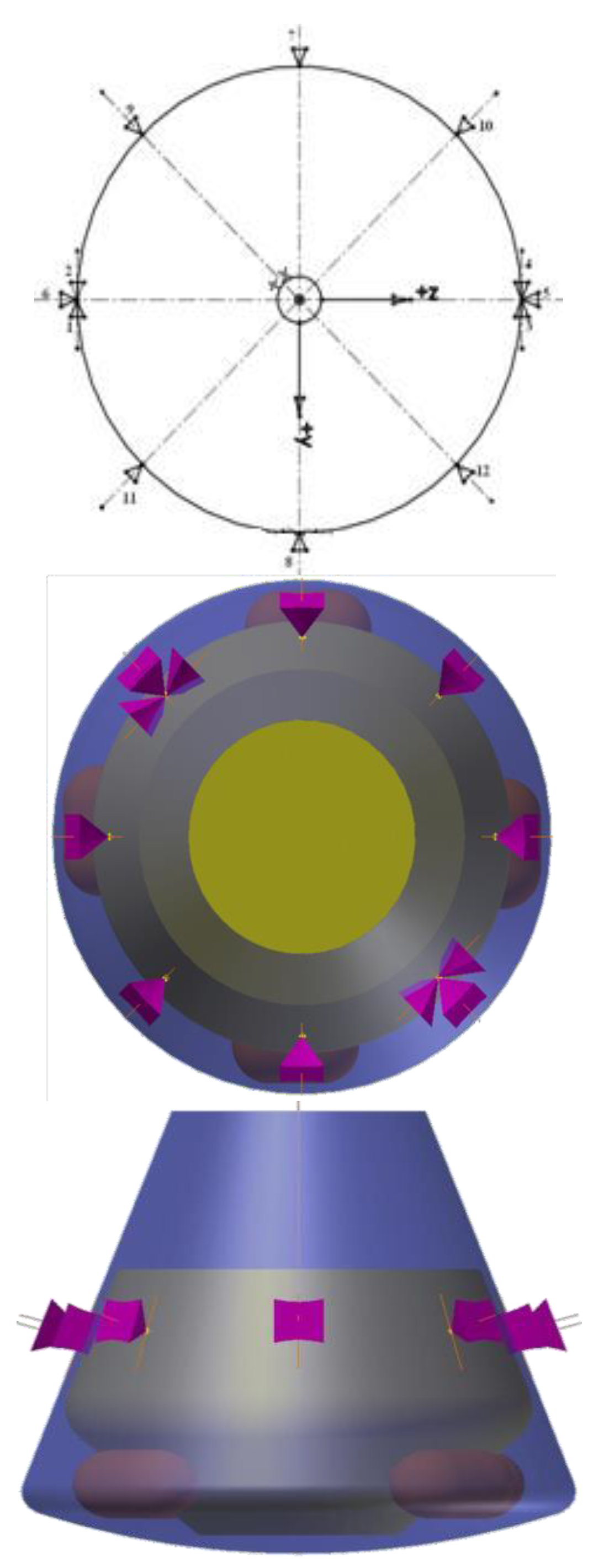
Figure 6.
Layout of 12 Thrusters from Top View on the Spacecraft Body (Type III Configuration).
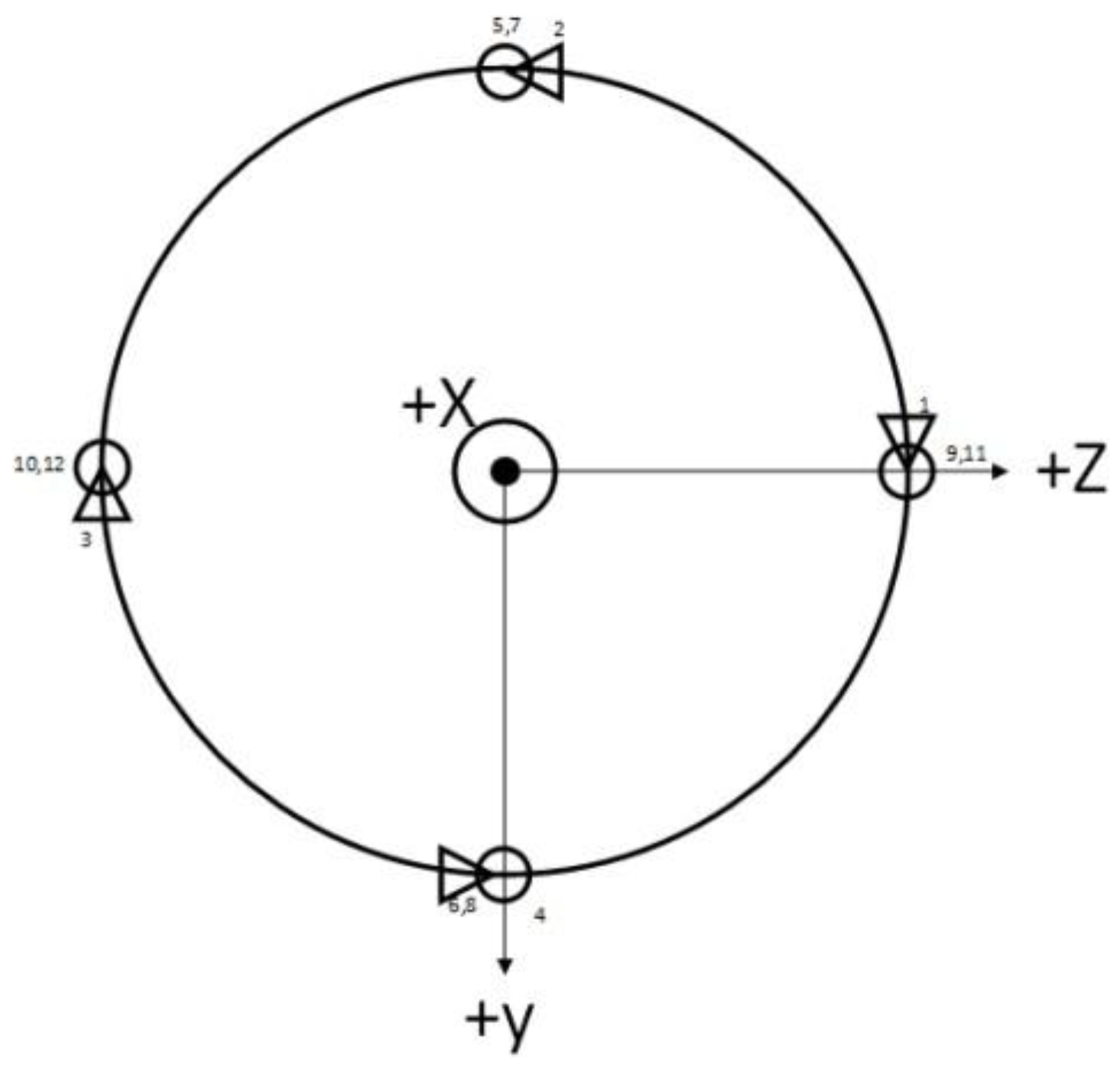
Figure 7.
Dual Thrusters of the Yaw Motion Control Channel.
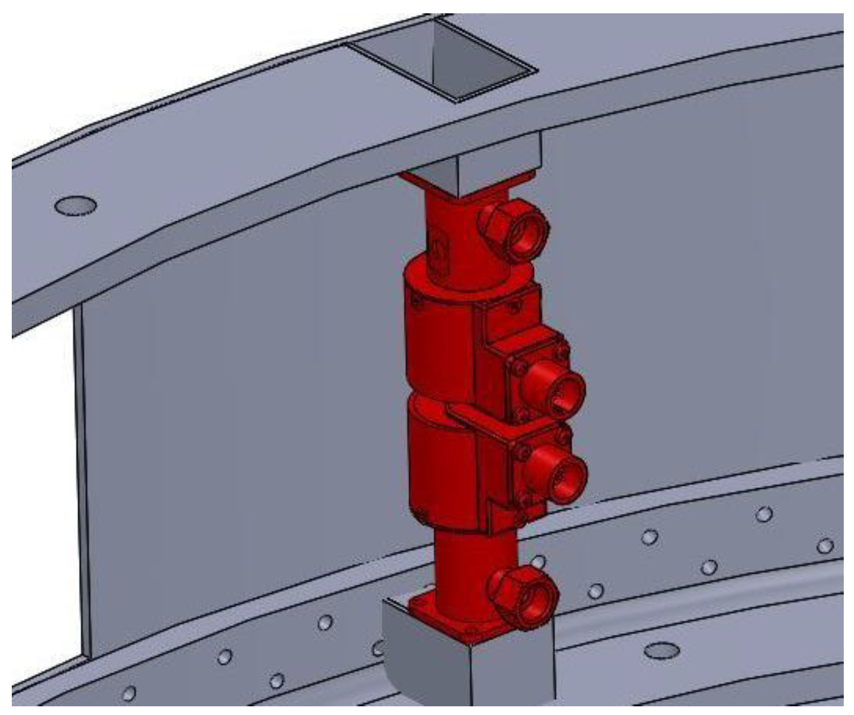
Figure 8.
Quad Thrusters for Roll and Pitch Motion Control.
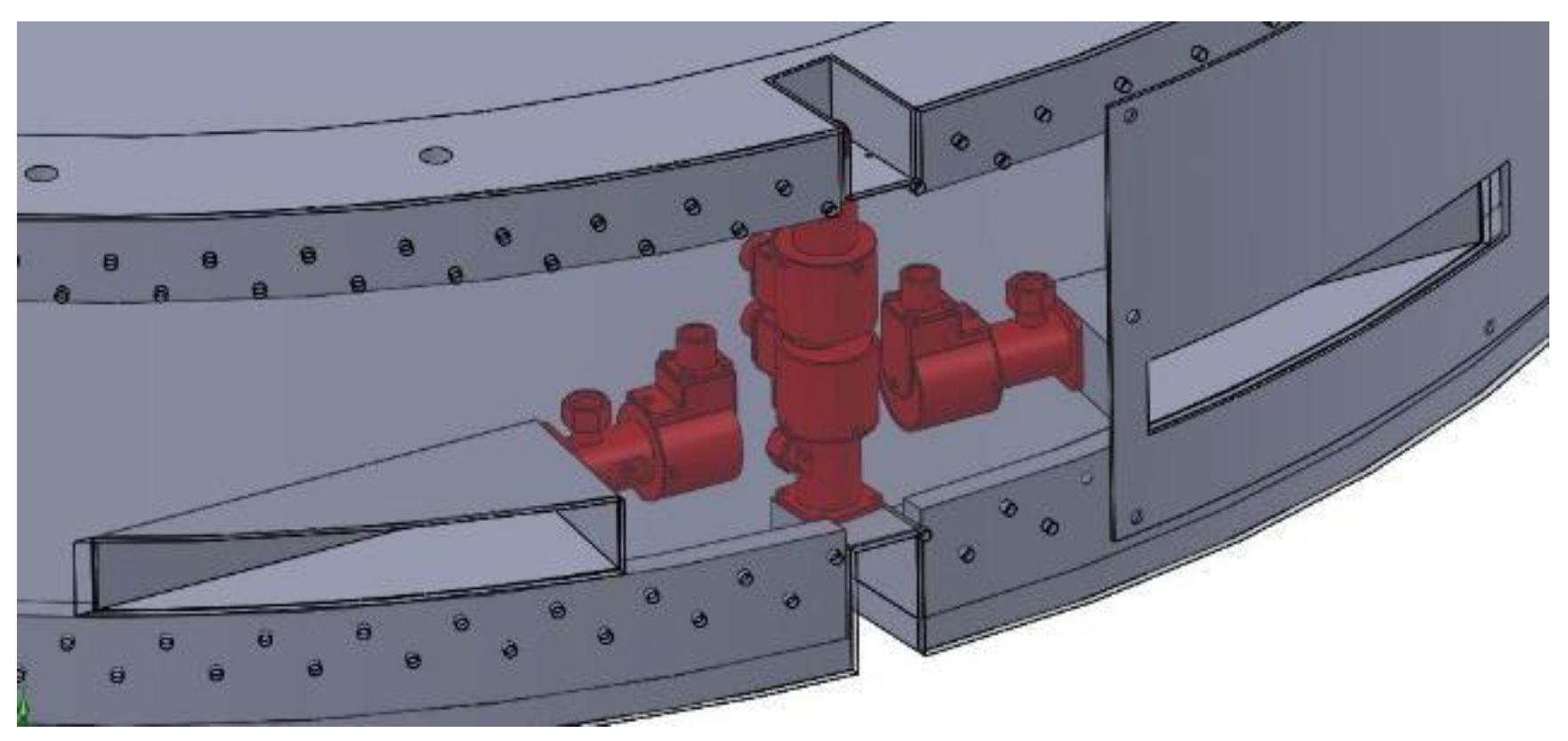
Figure 9.
Arrangement of Thruster Assemblies on the Service System Ring in Two Different View.
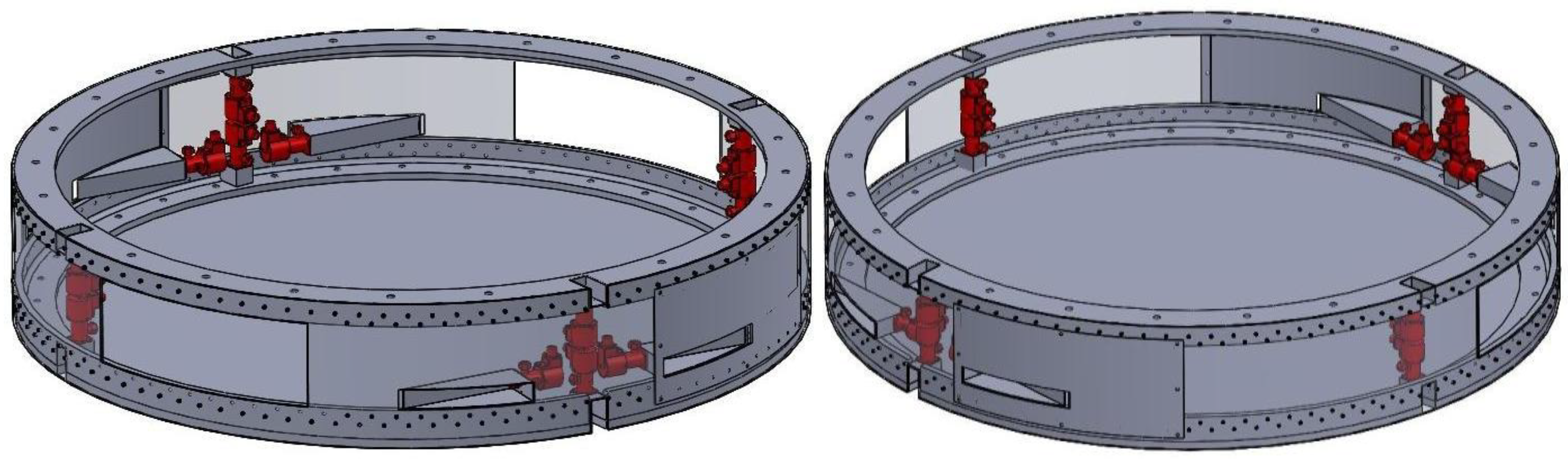
Table 1.
Final Parameters of the Thruster.
| Parameter | Value | Unit |
|---|---|---|
| Injector pressure drop difference | 3 | bar |
| Injector nozzle diameter | 0.6 | mm |
| Injector length | 1.8 | mm |
| Injector bevel angle | 90 | degrees |
| Mass flow rate | 0.005 | kg/s |
| Chamber pressure | 16.4 | bar |
| Catalyst bed loading | 28.29 | kg/m2·s |
| Chamber length | 0.03 | m |
| Chamber diameter | 0.015 | m |
| Nozzle throat diameter | 0.00214 | m |
| Nozzle exit diameter | 0.00364 | m |
Disclaimer/Publisher’s Note: The statements, opinions and data contained in all publications are solely those of the individual author(s) and contributor(s) and not of MDPI and/or the editor(s). MDPI and/or the editor(s) disclaim responsibility for any injury to people or property resulting from any ideas, methods, instructions or products referred to in the content. |
© 2025 by the authors. Licensee MDPI, Basel, Switzerland. This article is an open access article distributed under the terms and conditions of the Creative Commons Attribution (CC BY) license (http://creativecommons.org/licenses/by/4.0/).
Copyright: This open access article is published under a Creative Commons CC BY 4.0 license, which permit the free download, distribution, and reuse, provided that the author and preprint are cited in any reuse.


