
Submitted:
09 July 2025
Posted:
10 July 2025
You are already at the latest version
Abstract
A novel core-shell nano composite is formed by the carbon coating treatment for aluminum nanoparticle (ANP). As a typical energetic material, the injection of heat energy appeared before its ignition and combustion behaviors. In this study, molecular dynamic (MD) simulations are applied to uncover phase transition mechanism during the heating process and analyze the change of core-shell boundary. Those obtained results show that the critical melting point of carbon coated ANP (diameter: 8 nm) is around 1050 K. It is also an inward diffusion process, as the liquid phase firstly produces on surface zone and then develops toward the aluminum core. The mechanism of this development trend is highly relate with the amorphous phase of carbon coating and the coupling zone for both carbon and aluminum. With low interatomic potential energy, liquid phase is transited earlier than other zone. Finally the core-shell ratio largely affects the critical melting point, as the thickness of pure carbon coating decrease with the increase of core-shell ratio.
Keywords:
molecular dynamics
; carbon coating
; aluminum nanoparticle
; core-shell nanocomposite
1. Introduction
With the development of aerospace dynamic technologies, chemical compositions of propellants are discovered, tested and uncovered in many researches. ANP, as a typical metal additve, has been received with concern in applications of solid propellants, such as composite, fuel-rich, and composite modified double base (CMDB) propellants [1]. This is because ANP could effectively reduce the production of toxic gas without any negative effect on the compensation of performance, meanwhile the combustion rate could also be increased as high as 54% [2]. Due to the effect of high specific surface area, those positive change from ANP are more highlighted than that from micro-sized particles [3]. However, high energy density, reactive activity and specific surface area also bring limitation issues, like agglomeration [4] and surface oxidation. It is reported that the alumina shell of ANP will not break or shatter during the oxidation peocess, but deformations may occue from the shell zone [5]. The extent of shell deformation is determined by the diameter of paricle. Besides, an oxidation kinetics study [6] uncovered that the growth of γ-Al2O3 crystallites was combined with the diffusion of surface and grain bounday, which was one of factor for high oxidation rate. Meanwhile, the anions transport through an amorphous and underlying nanocrystalline oxide layer was found as well. The oxidation kinetics of aluminum is highly related to the oxygen concentration, so the additions of non-oxidizing gas could increase the critical oxidation temperature of aluminum powder [7].
Despite the adjustment of gas environment, surface passivation of ANP is another reasonable choice for the inhibition of oxidation. The surface passivation of ANP has been widely studied by those experimental characterizations [8,9] and some numercial simulations [10,11,12]. Apart from those investigated coating applications like organic molecules or metals [13], carbon is another potential coatings material for the surface passivation of ANP. It is said that carbon based graphene has shown well behavied anti-corrosion performances, which enables plenty of application for this novel carbon based 2-D materials [14]. If the ANP could be encapsuled by spheral carbon to form a core-shell nano composite, then a sufficient protection could be prepared on the ANP surface. The preparation of this type of composite has been reported by using the spark plasma sintering (SPS) method, then the prepared composite showed higher Vicker’s hardness and thermal conductivity than that of bulk aluminum [15]. Next, the high energy ball mill is also feasible for the production of carbon-aluminum composite, which has shown high thermal conductivity and low thermal expansion coefficient [16]. Futher, the carbon coating could enven encapsule liquid metals to inhibit some intrinsic limitations [17].
As a metal propellant, the combustion of ANP mainly includes two stages, including the injection and release of heat energy [18]. Especially, the enegy injection or heating stage of ANP is critical for the overall development, because the break and melting of ANP determines the diffusion of oxygen atoms. Inrecent years, many studies have uncovered this mechanism for original ANP. However, the inner changes or behvior of grapheme coated ANP nano composite under linear heating process is still not clear. Firstly, the ANP with over 850 aluminum atoms has presented an obvious transition between solid and liquid phases [19]. But the solid-liquid phase stability with existence of carbon coating on ANP still need to be further investigated, as this is highly related to the melting point of nano composite. Secondly, it is said that a compressive force is added the ANP core with the increase of critical point and fusion heat [20]. For carbon coating, the boundary between core and shell may change the loading effect on aluminum core. Thirdly, the application of ReaxFF force field has demonstrated the feasibility and advantage of non-fixed interatomic potential [21]. Which enables the MD simulations of chemical reaction in the future. With the existence atom type of carbon, MD simulations of carbon is worthwhile to be performed as well.
Due to the limitation of length, this study is mainly focused on the change of core-shell structure and its boundary. According to the preciseness and reliability of relevant studies on ANP and its coating, MD simulations are generally applied to uncover the phase transition stages in atomic scale. The innovativeness of this study is demonstrated on the modelling and point to point analysis of cor-shell boundary between aluminum and carbon.
2. Methods
2.1. Molecular Dynamic Simulations
For an uncoated ANP with a diameter of 8 nm, it only contains for about 1.6×10⁶ aluminum atoms [22]. While at this atomic scale, MD simulation could be applied as a potent instrument to investigate thermal dynamic and structural parameters of alloys and nano composites, such as titanium alloys [23,24] or even organic coated ANP [12,25]. By solving atomic motion equations from Newton’s classical mechanics, MD simulations could offer a step by step understanding of aluminum and carbon atoms in carbon coated ANP. In this study, an open access classical MD program: LAMMPS [26] (Version: 64bit-28Mar2023) is applied to simulate all carbon coated models with various conditions. LAMMPS applies the Velocity-Verlet algorithm to obtain all atomic trajectories due to its convincing dynamic results. Besides, the interatomic force field could compute attraction and repulsion effect between pairs of atoms or clusters. The Tersoff type force field applied in this study was developed by Plummer et al [27,28].
2.2. Computational Models
Because the melting point of ANP is highly related to it radius, it is reasonable to model an ANP with same size. As shown in Figure 1, there are totally three models simulated in this study. The ANP core of each model is modeled similar to an ideal sphere with a diameter of 8 nm. The crystal stricture of ANP obey the parameter of bulk aluminum, which is a typical face-centered cubic (FCC) lattice with a constant of 4.046 Å. Then the carbon coatings are modeled with uniform thickness. Due the demand of discussing the core-shell ratio, The carbon coating is modeled with three different thickness, including 0.5 nm, 1 nm and 1.5 nm. In order to obtain carbon coated ANP models with low potential energy, all models were performed after thermal relaxation between 300-400 K. In this study, the visualization and rendering of all models were completed by OVITO program [29].
2.3. Simulation Parameters
Those modeled ANP with various carbon coatings above are placed in a cubic simulations box, shown in Figure 2. The 3-dimensional size of simulation box is 20×20×20 nm3, and the plane boundary on each direction is set as periodical condition. Other space of simulation box is vacuum space, which eliminates potential influence from other molecules or clusters.
Before performing the injection of heat energy, all models were optimized by Polak-Ribiere version of the conjugate gradient (cg) style algorithm to initialize the MD simulation with low energy. Then the canonical (NVT) ensemble is applied to linearly control the model temperature by Nose-Hoover thermostatting method. During the injection of heat energy, the temperature of overall model is increased from 300 K to 1300 K in 1 ns. The atomic coordinates of each atom is interacted for totally 1×10⁶ steps with the time step of 1 fs. The thermal damping coefficient of thermostatting algorithm is 100 fs, in order to limit the fluctuation of raising temperature.
3. Results and Discussion
3.1. Phase Transition Process Under High Temperature
To some extent, heating process could be considered as a previous step for the ignition of nano composite. The heating of nano composite relies on the injection of heat energy on each atom. In order to eliminate potential effects from heating rates or stability, the temperature rising line is controlled to be linearly by thermal state algorithm. As Figure 3 shows, the temperate plot has already achieved its initial demand. The deviation of temperature raising rate could almost be ignored. While at the beginning, the aluminum core was about 300 K and it is stabilized in FCC phase, even after geometry optimization. However, it seems that the carbon coating was in the state of amorphous phase even at 300 K. This is because of the low potential energy on surface carbon atoms and the limitation of coating thickness. On this occasion, inter-atomic binding effect is too weak to keep the stability of lattice structure. Then with the climb of temperature plot, the entire structure of carbon coated ANP turn into the liquid phase. While at 1300 K, the boundary of aluminum core and carbon shell could be noticed. The final temperature distribution is unique without any heat concentration in this process.
The phase transition from FCC and amorphous phases to liquid phase was not happened immediately, in other words, it is more likely to be step by step transition process. Figure 4 shows the developments of atomic temperature from beginning (300 K) to the end (1200 K). It seems that the temperature on aluminum core and carbon shell is almost equal in each direction. The observed unique temperature distribution were not only happened in liquid phase, but also in FCC and amorphous phases. Therefore, the solid boundary of aluminum core and carbon shell has little inhibit effect on the heat diffusion effect, and will not limit the heat on either core or shell. Beside, the FCC phase zone in aluminum core was reduced at the temperature range from 1000 K to 1200 K. It is deduced that the phase transition process mainly happened in this stage. However, the snapshot of core-shell particle at 1100 K in Figure 4 also show a unique distribution of atomic temperature. Therefore, and phase transition of this core-shell nano composite is mainly presented on the injection of heat or kinetic energy, and it has no limited effect on the temperature distribution. Furthermore, this temperature-phase relationship is maintained before and after the transition of both (FCC → liquid) and (amorphous → liquid) process.
Despite the evaluation of atomic temperature, the structure identification from OVITO could demonstrate the state of phase transition for carbon coated ANP more clearly than previous one. As shown in Figure 5, the FCC phase of aluminum core was surrounded by carbon coating layer with amorphous phase. Due to the internal stress from carbon coating, several crystal defects are identified in aluminum core zone, while at 300 K, 400 K, 500 K and 600 K. Then with the continuously raising trend of overall temperature, aluminum atoms obtained more kinetic energy to release the internal stress. To some extent, the crystal structure is optimized before the melting point.
According to the snapshot change at 1050 K, it seems that the phase transition point of carbon coated ANP is around 1050 K. Besides, the migration of phase boundary is a centripetal motion, from surface to core. So the phase transition of carbon coated ANP started at the carbon coating layer. This is accurately a (amorphous → liquid) process. Then the amorphous-FCC boundary is substituted by the liquid-FCC boundary. The phase transition is continued until all carbon and aluminum atoms are in liquid phase.
In MD simulations, the magnitude of inter-atomic potential energy affects the stability of atoms and the intensity of their interactions. Changes in this potential energy between atoms can trigger alterations in the state of matter. Also, the formation of chemical bonds is closely related to the potential energy between atoms. The potential energy when different atoms combine has unique characteristics, and temperature changes may lead to adjustments in the potential energy between atoms. Figure 6 shows the plot of overall potential energy of nano composite from 300 K to 1300 K. While in solid phase, the increase of temperature bring up the in-situ thermal vibration of each atomic. On this occasion, the inter-atomic distance is enlarged and atomic interactions is weakened. This change demonstrated in the potential energy is the decreasing trend of plot. When the temperature of nano-particle reach 1050 K, a step response appears in the potential energy plot. This is because the in-situ thermal vibration is substituted by thermal migration. According to the snapshot of particle cross-section, it seems that the region of carbon layer is coated with lower potential energy than aluminum core. This is also the reason why phase transition started from surface to the core.
Mean Square Displacement (MSD) is an important parameter in MD simulations, which is used to measure the positional deviation of atoms after their motion over time. Figure 7 is the MSD plot of aluminum core and carbon shell in this nano-composite model. It is shown in Figure 7 that the single aluminum core plot explicitly demonstrates the phase transition at 1050 K. In which the climbing rate of plot at liquid phase zone is much higher than that in FCC solid phase zone. This is because the (FCC → liquid) phase transition allows the thermal migration of aluminum atom in a larger region than before. Which high kinetic energy, the extent of diffusion gets higher and higher. As for another plot for carbon shell. It seems that the stability of diffusion is not as same as aluminum. Besides, there is no obvious change before and after 1050 K. The reason for this change is related to the difference between FCC and amorphous. Although they are both solid phases, the atomic interaction of amorphous phase is much lower than that of FCC phase. With low atomic restrictions, carbon atom are prone to leave its original site. Besides, the snapshot of Figure 7 also illustrates desorption of carbon atoms or pairs in heating process. This further weakened the atomic restrictions in coating layer. On this occasion, the critical point of MSD in carbon shell is hided. Then the plot in Figure 7 is more likely to be presented as a fluctuating line.
3.2. Evaluation of Core-Shell Boundary Before and After Molten
It is said that the growth of carbon coating on aluminum surface is mainly motivated by hydrocarbon precursors, and in this process the C-C bond is stabilized as well [30]. However in this study, hydrocarbon species were not applied in the modelling of core-shell structure. With the lack of precursors, the core-shell boundary in low temperatures is not easy to be expended. According to the cross section snapshot in Figure 5, the core-shell boundary is a typical carbon-aluminum coupling zone with the critical lines of full carbon and full aluminum on each side respectively. Figure 7 is the micro structure of core-shell boundary colored by parameter. It seems that the initial core-shell boundary was formed by a simultaneous and opposite diffusion of carbon and aluminum atoms. In this process, more and more C-Al bond formed by breaking the Al-Al bond. Thus a clear boundary is illustrated by the FCC crystal phase and amorphous phase. Although the stabilized core-shell boundary has shown unique values of kinetic energy, the decline of potential energy is still left in the overall core-shell boundary zone, which largely affects the evolution of phase transition either inside or outside the boundary. According to the related structure around 300 K, it is verified that the state of parameter is stabilized to some extent.
Although the boundary of core-shell structure is stabilized at room temperature, the injection of heat energy still have potential effects from the diffusion of atoms. Figure 8 is the distribution of carbon atoms in the cor-shell boundary. These scatter plots are obtained from the Y-Z plane of spherical model and the thickness of cross section is 10 Ǻ. From the figure, it seems that the injection of heat energy has little effects if the temperature is below the phase transition point. As in this period, kinetic energy of atom is mainly represented by the in-situ thermal vibration, no further diffusion appears in the boundary zone. Then since 1050 K, the form of atomic kinetic energy is changed from in-situ thermal vibration to thermal diffusion. A new type of diffusion mechanism acts on the boundary, which is counter diffusion. In this mechanism, carbon atoms diffuses from high concentration zone to low concentration zone. So the more and more carbon atoms are diffusing inwards to the core direction. Meanwhile, aluminum atoms are diffusing through the carbon coating to the surface. Consequently, the width of cor-shell boundary is enlarged with the injection of heat energy above phase transition temperature. This trend is initially observed in Figure 8. However, due to the limitation of cross section thickness and the extremely short time step, this change is not visible enough in the scatter plot.
3.3. Effect of Core-Shell Ratio on the Heated Micro-Structure
As discussed above, the phase transition, from solid to liquid, of carbon coated ANP started since the outer surface of carbon coating layer. In practical preparation and applications, there is no deny that the diameter of nano composite is not unique, while the effect of coating thickness is still uncovered. In this section, a new definition for core-shell ratio is applied, which is obtained by the deviation of ANP diameter and initial coating thickness. Therefore, the core-shell ratio values for ANP with the 0.5, 1.0 and 1.5 nm thick carbon coating are 8, 4 and 2.7 respectively.
Figure 9 shows the development of total energy for entire nano-composite. Because the total energy of each model is obtained by the sum of potential energy and kinetic energy, similar step responses are presented in each plot of Figure 9. As discussed above, the frame of step response refers to the critical phase transition point. It is obtained that these points for nano-composite with core-shell ratios of 8, 4 and 2.7 are about 1025 K, 1050 K and 1075 K respective. In other words, the higher the core-shell ratios are, the higher the temperature for phase transition point will be. These ANP with thin carbon coating could be melted earlier than those with thick coating.
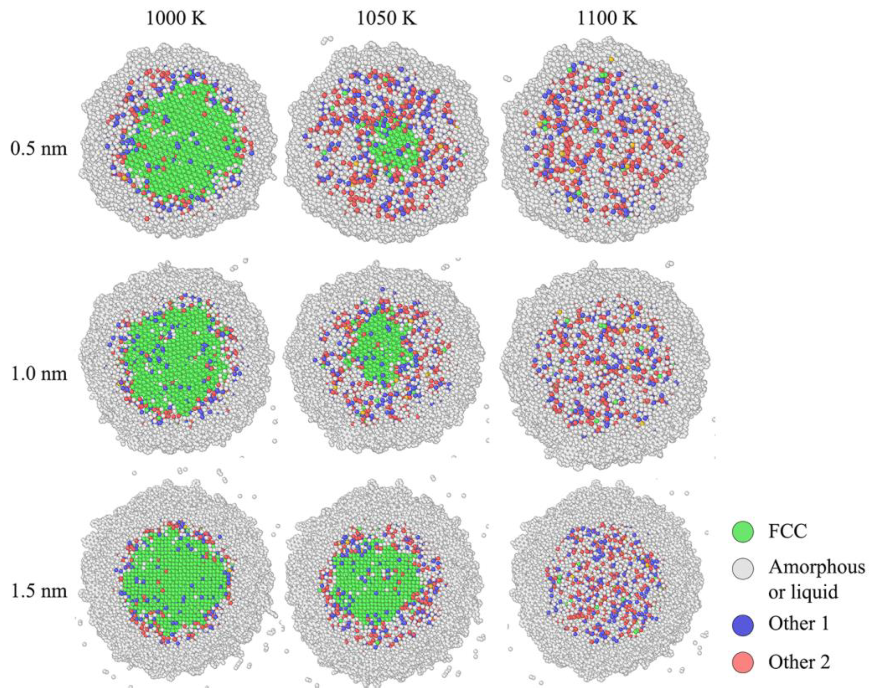
The mechanism of phase transition point affected by core-shell ratio is related to range of core-shell boundary. As presented in Figure 7, the entire structure of core-shell boundary for nano composite mainly includes the pure carbon coating zone and carbon-aluminum coupling zone with the critical lines of full carbon and full aluminum on each side respectively. Because the interatomic diffusion is limited at room temperature, the thickness of carbon-aluminum coupling zone will not be enlarged with the increase of coating thickness. In other words, the pure carbon coating zone in the nano composite with high core-shell ratio is relatively low. To some extent, this zone could be fully substituted by the coupling zone. Comparing with the former style, the coupling zone with low potential energy is prone to be melted in a reduced temperature. Figure 10 is the structural comparison of nano composite with three different core-shell ratios. At 1000 K, three nano composites are still under original state. While the temperature is as high as 1050 K, it is obviously shown that the solid FCC phase in 0.5nm thick carbon coated ANP is much smaller than other two. This is because the thin carbon coating was melted earlier than other those with thick coating layers.
4. Conclusion
Molecular scale simulations were performed to uncover the phase transition behavior of a novel core-shell nano composite, which was formed by the addition of carbon coating on ANP surface. According to those obtained results, it seems that the interatomic potential energy of nano composite is lower than that in aluminum core. Therefore the initial phase transition of it under the injection of heat energy is presented as the substitution from amorphous phase to liquid phase. Then the liquid phase diffuses from surface toe the core. Generally, this is a typical inward melting process. While in this process, the cor-shell ratio largely affects the critical melting point. It is obtained that the melting point of nano composite with the ratio of 8 is about 25 K lower than that with the ratio of 4. The main deviation of this phenomenon is related to the thickness of pure carbon coating zone.
Acknowledgments
This investigation was supported by the National Natural Science Foundation of China under Grant No. 92160201.
References
- Weiqiang Pang, Yang Li, Luigi T. DeLuca, et al., Effect of metal nanopowders on the performance of solid rocket propellants: A review [J]. Nanomaterials, 2021. 11: p. 2749.
- Uma Vellaisamy, Shelly Biswas, Effect of metal additives on neutralization and characteristics of AP/HTPB solid propellants [J]. Combustion and Flame, 2020. 221: p. 326-337.
- Ruochen Sun, Pingan Liu, Hui Qi, et al., Aluminium nanoparticle modelling coupled with molecular dynamic simulation method to compare the effect of annealing rates on diethyl ether coating and oxidation behaviours [J]. Journal of Molecular Graphics and Modelling, 2020. 100: p. 107667.
- Luigi, T. DeLuca, Filippo Maggi, Stefano Dossi, et al., High-energy metal fuels for rocket propulsion: characterization and performance [J]. Chinese Journal of Explosives and Propellants, 2013. 6: p. 1-14.
- Ying Li, Rajiv K. Kalia, Aiichiro Nakano, et al., Size effect on the oxidation of aluminum nanoparticle: Multimillion-atom reactive molecular dynamics simulations [J]. Journal of Applied Physics, 2013. 114(13): p. 541.
- Andrey, V. Korshunov, Oxidation of fine aluminum particles: thermally induced transformations in particle shells and kinetics of oxide nucleation [J]. Physical Chemistry Chemical Physics, 2024. 26: p. 27602-27616.
- Xiaoliang Zhang, Ronghan Guo, Xiao Feng, et al., Thermal oxidation characteristics and kinetics of micron aluminum powder in different ambient oxygen concentration atmospheres [J]. Processes, 2024. 12(11): p. 2408.
- Guanyi Wang, Huixin Wang, Qingzhong Cui, et al., Synthesis, Analysis, and Characterization of Aluminum Nanoparticles Coated with 2,2,4-Trimethylpentane [J]. Metals, 2023. 13(2): p. 322.
- Joseph Raj Xavier, S. P. Vinodhini, R. Ganesan, Innovative nanocomposite coating for aluminum alloy: superior corrosion resistance, flame retardancy, and mechanical strength for aerospace applications [J]. Journal of Materials Science, 2024. 59: p. 12830-12861.
- Ruochen Sun, Pingan Liu, Hui Qi, et al., Molecular dynamic simulations of ether-coated aluminum nano-particles as a novel hydrogen source [J]. Journal of Nanoparticle Research, 2019. 21: p. 72.
- Pingan Liu, Penghua Sui, Zhichao Feng, et al., Molecular dynamic investigations of aluminum nanoparticles coated by the mixtures of ethanol and diethyl ether with different molecular proportions [J]. Journal of Nanoparticle Research, 2020. 22: p. 240.
- Yi Liu, Aojie Li, Yuxin Lei, et al., Molecular dynamics simulation of palmitic acid molecular passivation affecting the surface activity of aluminum nanoparticles [J]. Scientific Reports, 2025. 15: p. 8287.
- Jing Guo, Ruochen Sun, Hui Qi, et al., Corrosion and magnetization analyses of iron encapsulated aluminum particles by numerical simulations [J]. Coatings, 2019. 9(9): p. 557.
- Gan Cui, Zhenxiao Bi, Ruiyu Zhang, et al., A comprehensive review on graphene-based anti-corrosive coatings [J]. Chemical Engineering Journal, 2019. 373: p. 104-121.
- Jinuk Hwang, Woo-Seong Tak, So Youn Mun, et al., Graphene encapsulated al particles for improvement of thermal conductivity in composites [J]. Materials, 2020. 13(16): p. 3602.
- Sunil Kumar Pradhan, Mihir Ranjan Sahoo, Satyajit Ratha, et al., Graphene-incorporated aluminum with enhanced thermal and mechanical properties for solar heat collectors [J]. AIP Advances, 2020. 10: p. 065016.
- Megan, A. Creighton, Michelle C. Yuen, Nicholas J. Morrisac, et al., Graphene-based encapsulation of liquid metal particles [J]. Nanoscale, 2020. 12: p. 23995-24005.
- Pingan Liu, Junpeng Liu, Mengjun Wang, Ignition and combustion of nano-sized aluminum particles: A reactive molecular dynamics study [J]. Combustion and Flame, 2019. 201: p. 276-289.
- Saman Alavi, Donald L. Thompson, Molecular dynamics simulations of the melting of aluminum nanoparticles [J]. Journal of Physical Chemistry A, 2005. 110(4): p. 1518-1523.
- J. Sun, S.L. Simon, The melting behavior of aluminum nanoparticles [J]. Thermochimica Acta, 2007. 463(1-2): p. 32-40.
- Junpeng Liu, Mengjun Wang, Pingan Liu, Molecular dynamical simulations of melting Al nanoparticles using a reaxff reactive force field [J]. Materials Research Express, 2018. 5: p. 065011.
- Ruochen Sun, Pingan Liu, Hui Qi, et al., Structural and atomic displacement evaluations of Aluminium nanoparticle in thermal annealing treatment: an insight through molecular dynamic simulations [J]. Materials Research Express, 2020. 6: p. 1250b9.
- Ruochen Sun, Guangbao Mi, Xu Huang, et al., Molecular dynamic simulations of Ti-6Al and Fe-12Cr alloys for their heat transfer and oxygen transport behaviors [J]. Modern Physics Letters B, 2024. 38(4): p. 2350263.
- Ruochen Sun, Guangbao Mi, Surface temperature field of Ti-6Al and Ti-48Al alloys under continuous laser ablation [J]. Rare Metal Materials and Engineering, 2024. 53(9): p. 2405-2412.
- Yue Chu, Lei Wang, Pingan Liu, et al., Combustion of Al nanoparticles coated with nitrocellulose/ethanol/ether molecules by equilibrium molecular dynamics simulations [J]. ACS Omega, 2023. 8(36): p. 32712-32728.
- Aidan, P. Thompson, H. Metin Aktulga, Richard Berger, et al., LAMMPS - a flexible simulation tool for particle-based materials modeling at the atomic, meso, and continuum scales [J]. Computer Physics Communications, 2022. 271: p. 108171.
- G. Plummer, H. Rathod, A. Srivastava, et al., On the origin of kinking in layered crystalline solids [J]. Materials Today, 2021. 43: p. 45-52.
- Gabriel Plummer, Garritt J. Tucker, Bond-order potentials for the Ti3AlC2 and Ti3SiC2 MAX phases [J]. Physical Review B, 2019. 100: p. 214114.
- Alexander Stukowski, Visualization and analysis of atomistic simulation data with OVITO–the Open Visualization Tool [J]. Modelling and Simulation in Materials Science and Engineering, 2009. 18: p. 015012.
- Sungwook Hong, Adri C. T. van Duin, Atomistic-Scale analysis of carbon coating and its effect on the oxidation of aluminum nanoparticles by reaxff-molecular dynamics simulations [J]. Journal of Physical Chemistry C, 2016. 120(17): p. 9464-9474.
Figure 1.
Cross section of uniform 8 nm ANP models with different thickness of carbon coatings, (a):0.5 nm; (b): 1 nm; (c): 1.5 nm.
Figure 1.
Cross section of uniform 8 nm ANP models with different thickness of carbon coatings, (a):0.5 nm; (b): 1 nm; (c): 1.5 nm.
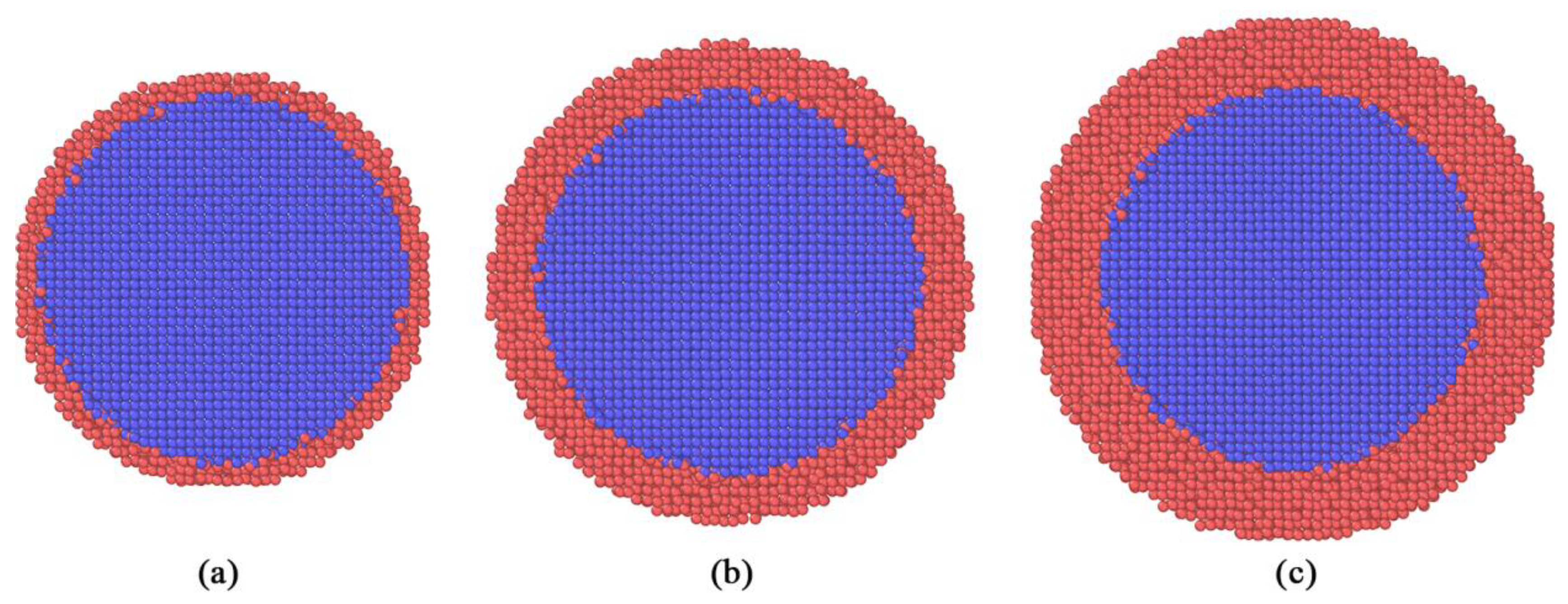
Figure 2.
Carbon coated ANP placed in a cubic simulation box.

Figure 3.
Liner heating process of carbon coated ANP from beginning to the end.
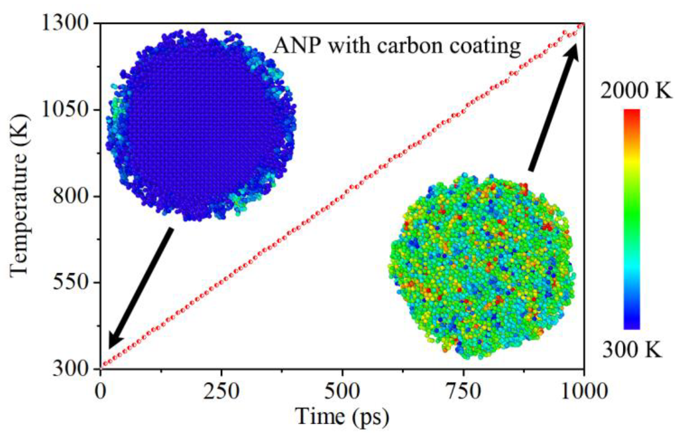
Figure 4.
Phase transition state of carbon coated ANP at each temperature point.
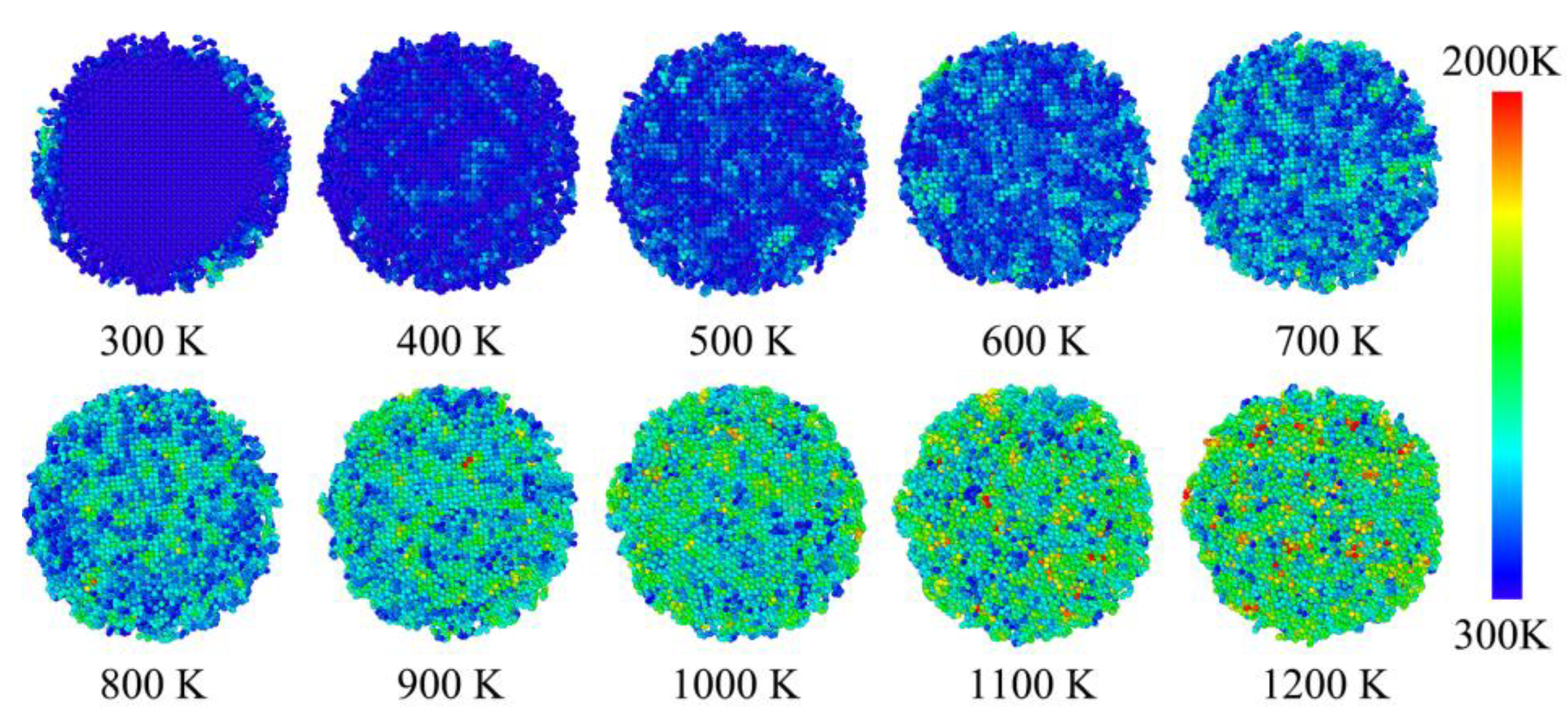
Figure 5.
Phase transition state of carbon coated ANP at each temperature point.
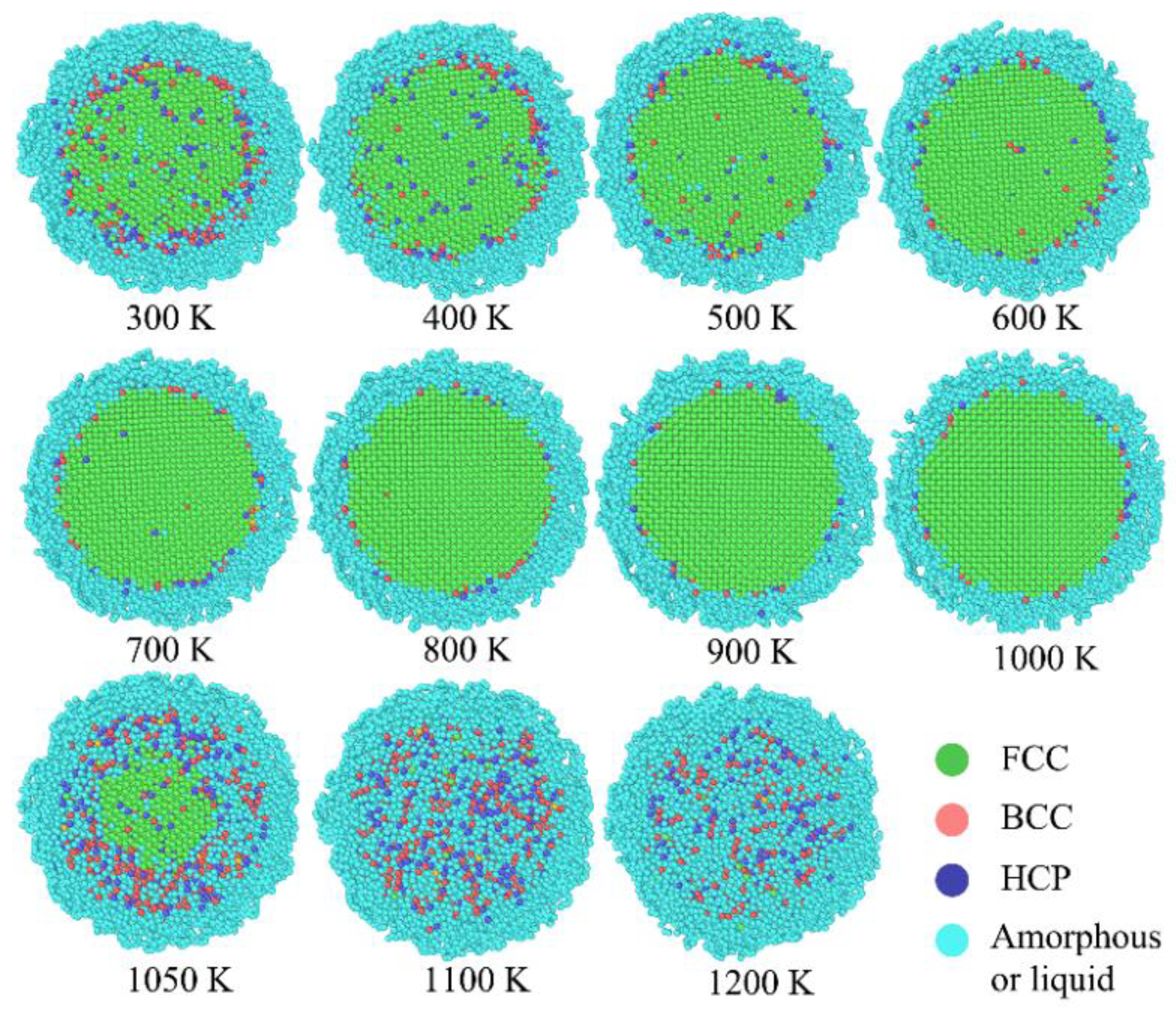
Figure 6.
Development of overall potential energy from 300 K to 1300 K and the atomic value distribution at 1300 K.
Figure 6.
Development of overall potential energy from 300 K to 1300 K and the atomic value distribution at 1300 K.
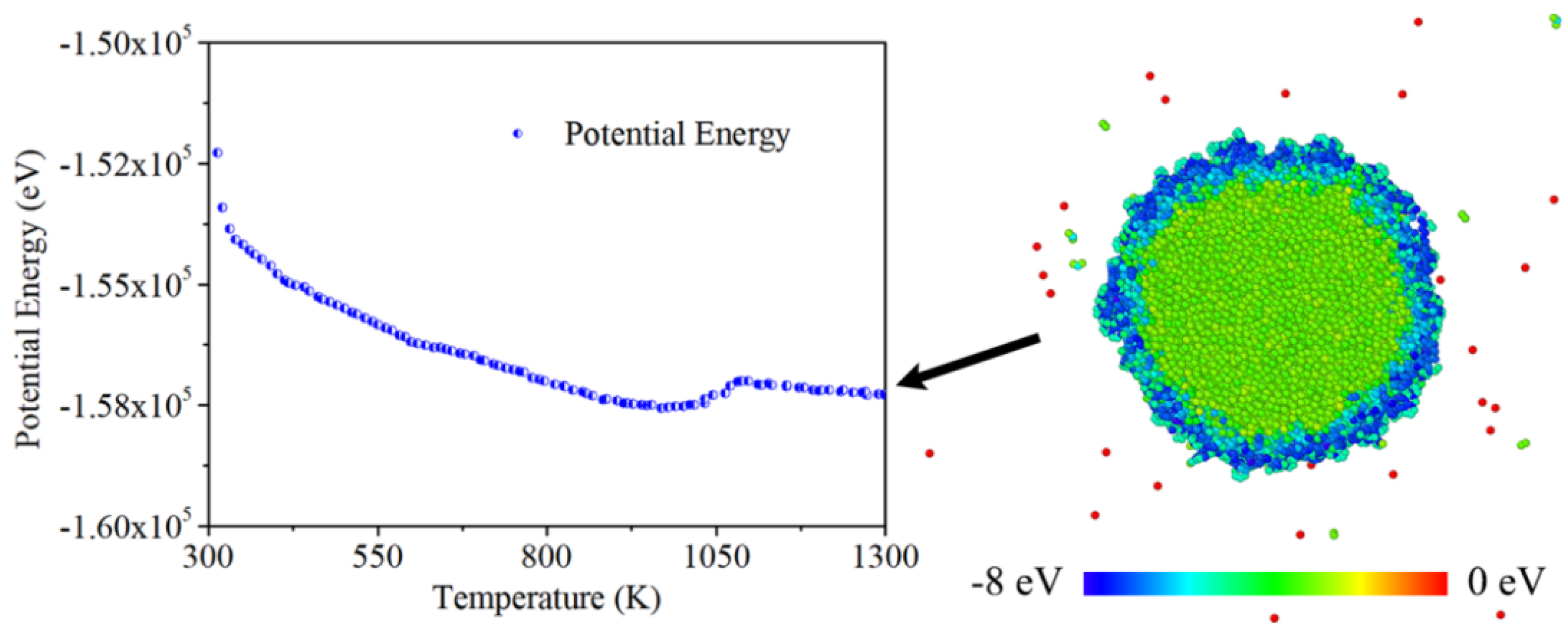
Figure 7.
The change of MSD for core (aluminum) and shell (carbon) in the heating process.
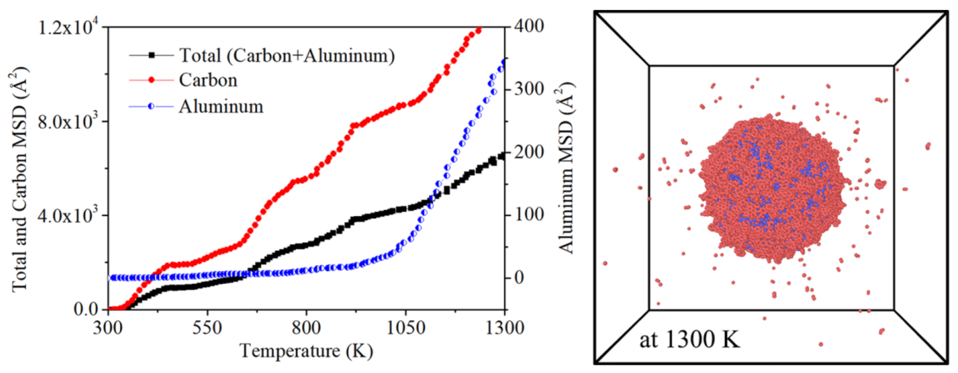
Figure 7.
The different state parameters of core-shell boundary at 300 K.
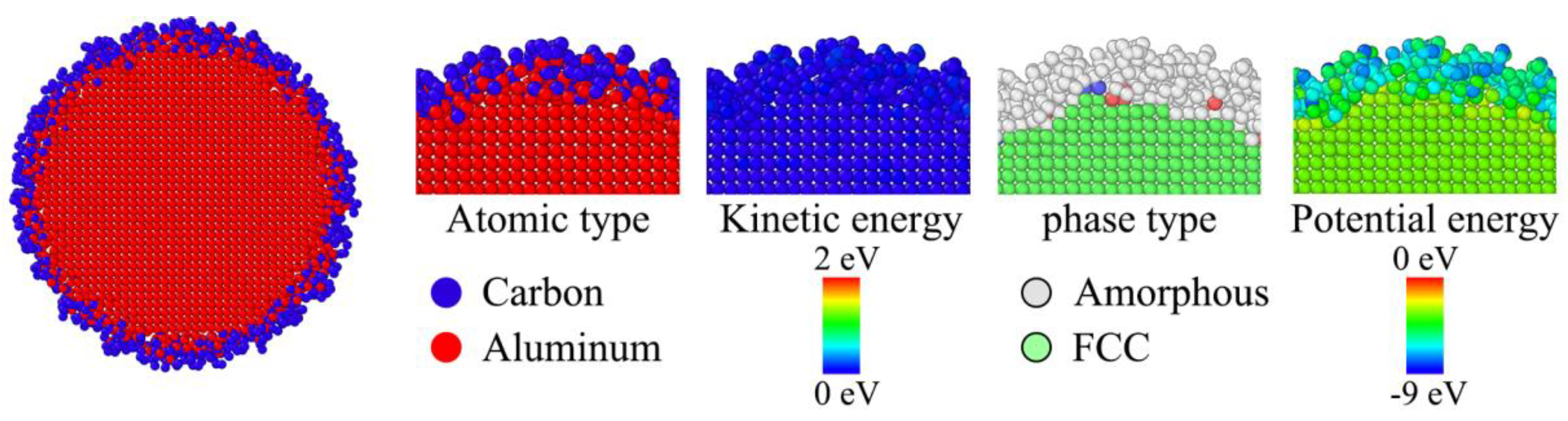
Figure 8.
Atomic distribution of core-shell boundary at 300 K, 800 K, 1050 K and 1300 K respectively.
Figure 8.
Atomic distribution of core-shell boundary at 300 K, 800 K, 1050 K and 1300 K respectively.
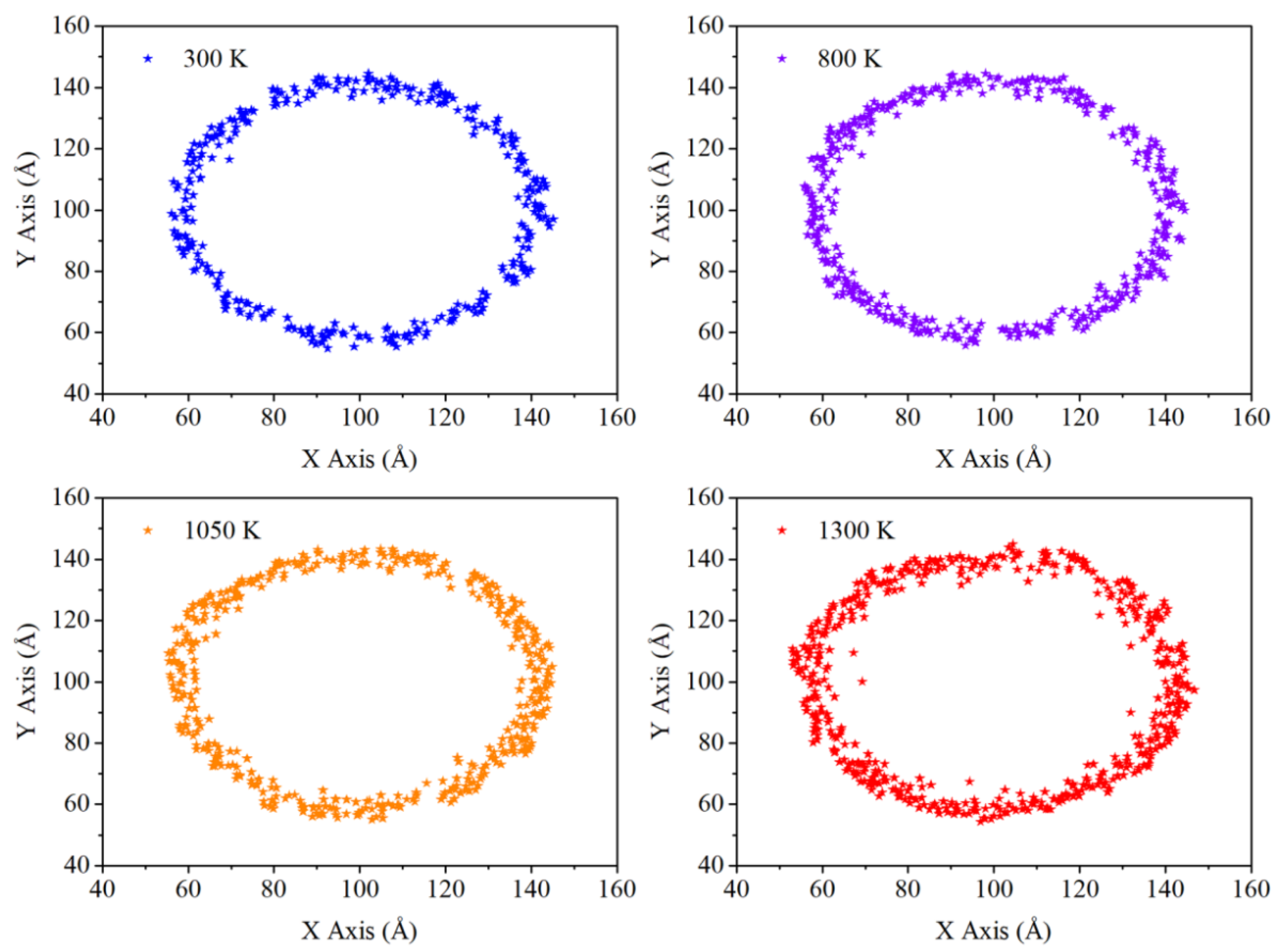
Figure 9.
Plots of total energy for ANP with different thickness of carbon coating layer.
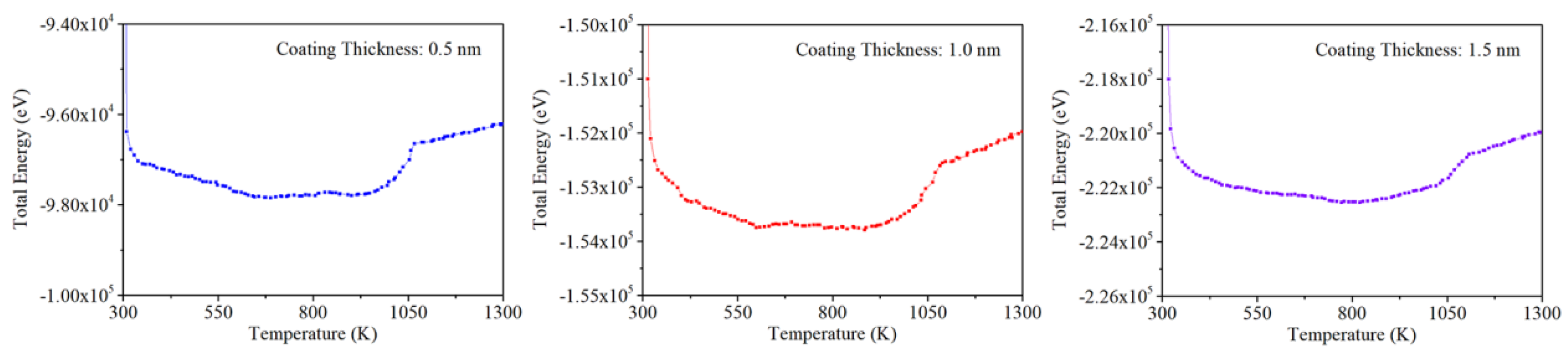
Figure 10.
Cross sections of carbon coated ANP during the phase transition process.
Disclaimer/Publisher’s Note: The statements, opinions and data contained in all publications are solely those of the individual author(s) and contributor(s) and not of MDPI and/or the editor(s). MDPI and/or the editor(s) disclaim responsibility for any injury to people or property resulting from any ideas, methods, instructions or products referred to in the content. |
© 2025 by the authors. Licensee MDPI, Basel, Switzerland. This article is an open access article distributed under the terms and conditions of the Creative Commons Attribution (CC BY) license (http://creativecommons.org/licenses/by/4.0/).
Copyright: This open access article is published under a Creative Commons CC BY 4.0 license, which permit the free download, distribution, and reuse, provided that the author and preprint are cited in any reuse.


