Submitted:
10 December 2024
Posted:
11 December 2024
You are already at the latest version
Abstract
An experimental study of the effect of spatially localized super-large-scale motion structures, propagating in a laminar gas impinging jet, on the dynamics and heat transfer was carried out. A hot-wire anemometer, a high-speed 2D PIV with a frequency of 7 kHz and gradient heat flux sensors were used as equipment. Air and carbon dioxide used as working gases. Puff-type superstructures with a longitudinal size of up to 20-30 nozzle diameters formed in a long pipe in a laminar-turbulent transition regime. These structures have a complex internal topology. Jet containing superstructures impinging on an obstacle leads to deforming of the flow near the surface and a decrease in heat transfer at the stagnation point. Data are obtained on local heat transfer in the region of the flow stagnation point at large distances to the obstacle (h/d = 20) in the Reynolds number range of 250-10000. It is shown that a laminar flow in a jet source corresponds to a more localized heat flux compared to the case of a turbulent regime in the source. The maximum heat transfer is achieved not for the Poiseuille profile in the channel, but in the case of a transitional regime with a small percentage of turbulent vortex structures
Keywords:
impinging jet
; vortex structure (puff)
; heat transfer
; intermittency
1. Introduction
As is known, heat transfer enhancement is a intensively progressing and developing problem [1]. From the point of view of the problem of heat and mass transfer enhancement in jet flows, the most widespread problem is the one with an impact jet [2,3]. Practice has shown that the most optimal option for heat transfer includes: a profiled confuser with a large constriction, a small distance from the nozzle to the obstacle h/d = 4 – 6, high Reynolds numbers (Re > 10000) [4]. The initial velocity profile in this case is top-hat, with thin boundary layers. The laminar-turbulent transition in such flows occurs within the initial section of the jet in the mixing layer (x/d = 3 – 4). In this zone, the linear mechanism of disturbance growth associated with the Kelvin–Helmholtz instability quickly transforms to a nonlinear stage; as a rule, the subharmonic mechanism of transition to turbulence is realized [5]. The initial disturbances quickly transform into coherent structures, with their characteristic size amounting to several nozzle diameters. The maximum extremum is located at the characteristic radius r/d = 4 [4]. This “ideal” scenario is often violated. In real flows, the initial conditions have a strong effect: the velocity profile and the level of turbulence in the core and in the boundary layer, the relative thickness of the boundary layer, the ratio of densities in the jet and the surrounding space [6]. To increase the heat transfer coefficient on the plate, various methods of influencing the jet are usually used: acoustic radiation, mechanical vibration of the nozzle or supply tract, use of gas discharge, and others [4,7].
In practice, jets also flow out of other sources, most often from holes, pipes, and non-cylindrical channels. A significantly smaller number of works are devoted to the study of instability of jets which have sources other than confuser nozzles [8,9,10]. In recent years, such works have been published because of the development of microfluidics [11,12,13]. The instability for the initial parabolic velocity profile in the jet was mainly studied by analytical and numerical methods [14,15,16]. In our works [12,17] it was shown that the instability region in this case significantly increases compared to the top-hat profile, and the transition zone to turbulence in such jets can reach large values of x/d = 200–300. It was also shown that in the range of Reynolds numbers of 2000–3500, the coordinate of the transition to turbulence can significantly decrease. In the case of a variation in the initial velocity profile, the problem of the relationship between two modes is still relevant [18]. Thus, in the mixing layer in the initial section of the jet, the shear layer mode prevails, and in the main section of the jet, jet column mode. The area of our research in this case relates to the range of Reynolds numbers of 1800–4000. It is known that at such Reynolds numbers in long cylindrical channels, a transition to turbulence through intermittency is possible (Pomeau-Manneville scenario, 1980) with the formation of large-scale vortex structures such as puff (superstructures) [19,20].
One of the modern approaches to heat transfer intensification is the method of controlling transfer processes in jet flows using large-scale structures. This method is well developed in relation to impact jets. The main structure by which heat and mass transfer on the surface is intensified is the so-called coherent structures that are formed directly in the jet. It was previously established that large-scale structures can make a significant contribution to the processes of momentum, heat and mass transfer, their effect can be up to 40% [21]. The most famous of them are coherent structures in turbulent jets of liquid or gas at high Reynolds numbers [22]. The primary cause of the formation of coherent structures in turbulent flows is most often called the processes of hydrodynamic instability [23]. At the same time, there is another point of view, according to which large-scale structures can be a consequence of instability of turbulent flow [23]. By using coherent structures, an increase in heat transfer of up to 15-25% is achieved.
In contrast to the above-described mechanism of formation of coherent structures directly in the jet (the characteristic size is on the order of several nozzle diameters) [21], ultra-large-scale structures (superstructures or “puff”, the characteristic size is on the order of 20-30 nozzle diameters) are formed in jet sources (long tubes or channels) as a result of the laminar-turbulent transition [19,20,24]. The size of these large-scale formations, as our experiments have shown, is preserved in the near field of the jet [25,26]. Such superstructures (size 20-30 nozzle diameters) are significantly larger than coherent structures having size 2-4 nozzle diameters and typical for turbulent impact jets. At the same time, low Reynolds numbers of transition to turbulence in tubes and channels (Re=1800-4000) allow to significantly reduce of the cooling gas rate, compared to turbulent flow regimes (Re>10000) at the same levels of heat transfer in impact jets. Our first experiments using the intermittent mode showed an intensification of heat transfer at the stagnation point of the impact jet up to 600% [27].
The study of such superstructures was the subject of an international conference of the Euromech community in 2017 (July 12–14, 2017, Erfurt, Germany, https://586.euromech.org/). In the case of jets flowing out of long channels in the intermittent mode, we have previously found that the superstructures that form in the channels are quite stable in the near zone of the jet. In the works [25,26] we observed an intermittent nature of the flow (in time) in the jet: in the laminar phase of the flow, a classical mixing layer develops, in the turbulent phase, a superstructure is present in the near zone of the jet (x/d=20–30). Thus, the problem of intensifying heat transfer in impact jets using superstructures is a relevant and scientifically significant objective of the modern stage of the controlling transfer processes problem in gases and liquids.
2. Experimental Setup and Measurement Methods
The data on the flow dynamics at the laminar-turbulent transition in the pipe and the impingement of the jet containing turbulent superstructures on the obstacle were obtained using a high-speed PIV. The working gas (Figure 1) was supplied from a high-pressure vessel, the flow rate was also controlled using an El-Flow Bronkhorst flow regulator connected with computer. Carbon dioxide (CO2) was used as the working gas in the study of isothermal flow. The CO2 gas passed through an aerosol generator, in which it was seeded with small droplets of glycerol with a diameter of 3-5 μm, for flow visualization, then entered the working channel, which was a long round tube. The tube was made of aluminum and had an internal diameter of d = 8 mm, length L = 1.6 m, which was 200 calibers. The dynamic flow characteristics were measured using PIV at the pipe outlet, with the jet flowing through a 400 x 400 x 400 mm organic glass flow chamber. In the case of an impact jet, a rectangular 5 mm thick organic glass plate 150 x 150 mm was placed at a distance of 65 mm from the pipe edge perpendicular to the jet flow.
In the PIV experiments, the jet was illuminated by a laser sheet using a PhotronicsDM high-speed pulse laser. A PhotronSA5 camera with a 1 MP matrix was used for high-speed shooting. Video shooting in the experiments was performed at a frequency of 7 kHz. The images obtained by the high-speed camera were processed using the PIV method, as a result of which instantaneous velocity fields were calculated, from which time distributions of instantaneous velocity at the channel outlet were obtained. Fields of average velocities and turbulent pulsations was produced by their averaging.
The study of heat exchange in a jet flowing onto an obstacle was carried out on the setup shown in Figure 2. Air under pressure was supplied from the compressor to the receiver. Then the gas passed through a filter and was directed through a digital flow meter (Bronkhorst) along a silicone hose (with an internal diameter of 15 mm) to the jet source. The following were used as a jet source: 1) a brass tube with a diameter of d = 3 mm and a length of L = 1 m; 2) a profiled confuser (Vitoshinsky nozzle) made of photopolymer with a diameter of d = 3 mm and a compression ratio of 16. The outflow was carried out into the surrounding air under room conditions.
A two-axes coordinate device with a minimum step of 0.05 mm was used to move the jet source. The distance from the beginning of the jet to the plate was h = 60 mm (h/d = 20). The heat exchange section was made in the form of a copper plate with a diameter of 190 mm and a thickness of 50 mm. Heating was carried out using an electric heater, while the boundary condition Tw = const (Tw = 50–60 °C) was ensured. Miniature heat flux sensors (MHF) measuring 2 × 2 × 0.2 mm [28] were flush-glued to the plate surface. Six film heat flux sensors (HFS) are located along the radius of jet spreading over the surface. Thin-film heat flux sensors are made of bismuth single crystal with a purity of 99.99% [29]. The sensor consists of anisotropic thermoelectromotive elements (ATPE). ATPE is a material with anisotropic thermophysical and thermoelectromotive properties. Under the influence of heat flow, anisotropic thermoelectromotive elements generate a thermo-EMF perpendicular to the heat flow vector and proportional to the heat flow density [29]. The heat flux sensor (HFS) generates an electrical signal, which is used to calculation the heat flow values.
This device allows measuring the instantaneous heat flux Q’ in a frequency band of up to 3 kHz. The measured values of the instantaneous heat flux were recorded on the computer hard drive. Then, the average Q and root-mean-square q values of the heat flux were calculated based on the time series (sample size – 1×10^4). The plate and jet temperatures were measured by chromel-copel thermocouples made of 0.2 mm diameter wire. The HFS and thermocouples were connected to the automated data collection system via a preamplifier and an analog-to-digital converter (L-Card E14-140). The average values of the heat transfer coefficient α and the root-mean-square values of the heat transfer coefficient pulsations α’ were determined, respectively, by Q and q and the difference in wall temperature Tw and jet temperature Tj.
The air parameters (kinematic viscosity and thermal conductivity coefficient) required to calculate the Reynolds number Re = Ud/ν and Nusselt number Nu0 = αd/λ were determined from the flow temperature at the nozzle outlet. The experiments measured the instantaneous heat flux, gas flow rate through the nozzle or tube, plate and jet temperature in the initial section, and barometric pressure. The total standard measurement uncertainty in the range of Re > 200 was estimated as the volt-watt sensitivity of the HFS of 0.64%, δQ = 1-4% [29], δα = 2–6%, δNu = 3–8%, δRe = 2–7%. The dynamic characteristics in the jet were determined using a DISA55M hot-wire anemometer and a 55P11 miniature probe. The hot-wire anemometer measurement system was also computer-controlled.
3. Results
3.1. Dynamics of Puff-Type Superstructures in a Jet Flowing onto an Obstacle
As is known, large-scale “puff”-type structures (l/d~20-30) are observed in pipes in the laminar-turbulent transition region [19]. However, such superstructures have hardly been observed in the study of jet flows. Our experiments demonstrated the existence of superstructures in jet flows. The obtained instantaneous velocity fields made it possible to obtain time series of instantaneous velocity at any point in space within the working region (x=0-60 mm).
The velocity fields were exported to files containing the longitudinal and transverse velocity values for each vector of the instantaneous vector field and the coordinates corresponding to this vector. Then, from these files, using specially written programs, the time distributions of instantaneous velocities for points in space with specified coordinates inside the working area were extracted. The measurements were carried out using PIV in the near field of a submerged jet, using a tube d = 8 mm L = 1.6 m and CO2 as the working gas.
The sample contained 10918 values. Axial distributions of longitudinal velocity were used to identify superstructures in the flow. Disturbances were identified according to the following criteria. First, they should be obtained in the range of Reynolds numbers of the laminar-turbulent transition inside the pipe. Second, all disturbances of the actual velocity value on the axis should have a smooth leading edge and a steep trailing edge [19]. Third, they should have a large amplitude, at most an order of magnitude greater than the pulsation background of the laminar flow, since no artificial disturbances were introduced into either the pipe or the jet in the experimental procedure.
The obtained results showed (Figure 3) that from the comparison of the values of the axis velocity and at the radius r = 3-4 mm it follows that there is a correlation in a short time interval, i.e. at the moment of puff passage. Along the length of the jet the velocity at the axis constantly decreases, and at a distance of 60 mm a decrease in the axial velocity to ~0.25Um is observed. The level of velocity pulsations at the jet periphery is significantly higher than at the jet axis at times before and after puff passage. This is due to the fact that the Kelvin-Helmholtz instability at the initial section develops in the mixing layer, and not at the jet axis. From the analysis of time series at different distances from the axis it follows that the trailing front in the mixing layer (r = 4 mm, Figure 3a) slightly lags behind a similar front at the axis (r = 0, Figure 3c). It should be noted that local extrema on the axis (r = 0, Figure 3c) do not always correspond to local extrema on the jet periphery (r = 3-4 mm, Figure 3a, b).
All this indicates that the internal structure of the puff itself has a complex spatial character, which is consistent with previously obtained data from other authors. Apparently, the topology of such superstructures requires high-speed tomographic PIV methods of study.
The use of high-speed PIV makes it possible to trace the change in the spatial structure of the jet with good time resolution (dt=1/f=143 μs). In particular, using the fields of instantaneous velocities, the vorticity distributions in the plane of the laser sheet (x, r) passing through the jet axis were constructed. The instantaneous vector fields of velocity W=iUx+jUr were constructed taking into account the velocity components (Ux, Ur), where i, j are unit vectors along the axes (x, r). Based on these velocity fields, the vorticity distribution in the plane (x, r) was calculated using the formula ω = (∂Ur /∂x + ∂Ux/∂r).
The obtained vorticity fields (Figure 4b) showed that during the passage of the puff superstructure, secondary vortices can be generated in the near field of the jet, especially during the passage of the trailing edge (Figure 4a).
The study of the dynamics of the impact jet flow in the presence of puff-type superstructures was carried out in the flow regime with the intermittency coefficient γ = 0.5 and Re = 2462. PIV measurements in the case when the impinging jet was located in the center of the measuring region showed that the spreading on the surface of the jet onto the plates occurs symmetrically. There are no flow velocity asymmetries caused by mutual non-perpendicularity of the jet and the plate.
The symmetry of the flow allowed us to carry out measurements with half of the pattern of the jet flowing around the plate. The measurement area was shifted to the right by 30 mm. The average velocity field with the streamlines constructed by the vectors (Figure 5a) showed the presence of a toroidal vortex above the plate, as happens when laminar jets flow onto an obstacle. The instantaneous velocity fields with the streamlines constructed (Figure 5b) showed that the turbulent superstructures entering the jet from the tube generate secondary vortices that can significantly distort the flow in the toroidal vortex above the plate surface.
3.2. Heat Transfer in an Impinging Jet in the Presence of Puff-Type Superstructures
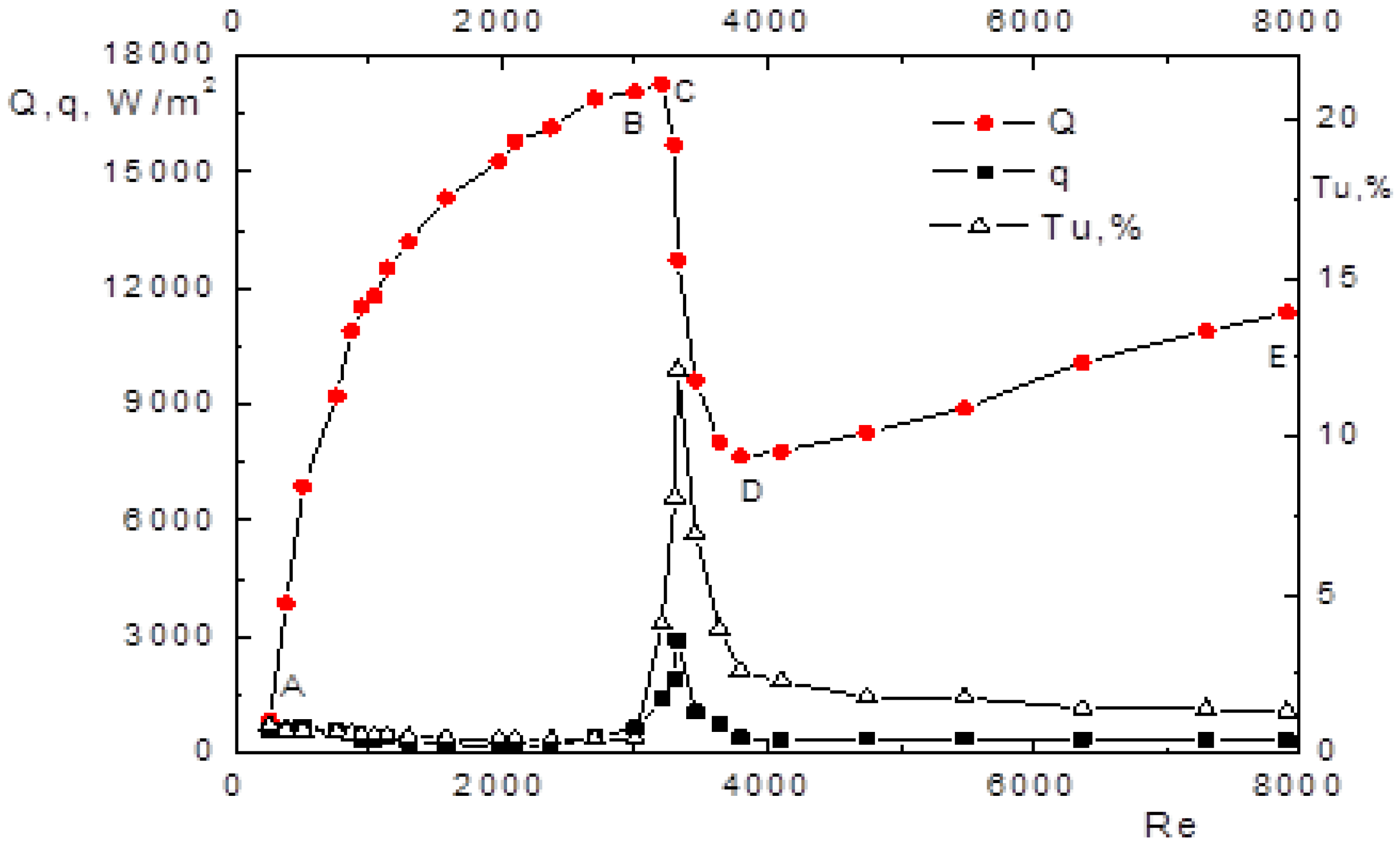
The results of the study of the impact jet flowing out of a long tube are shown in Figure 6. It shows the average Q and root-mean-square q values of the heat flux density at the stagnation point and the degree of turbulence Tu = u/Um × 100% at the tube outlet with a variation in the Reynolds number, where u is the root-mean-square value of the longitudinal component of the velocity pulsation. The classification of the flow in the impact jet was performed using the technique [30], which was based on the flow regime in the jet source (tube): laminar, transitional and turbulent. Diagnostics of the transitional flow regime in the tube is based on visualization and recording of large-scale turbulent structures (puff) using a hot-wire anemometer [30,31]. In Figure 6, section A-B (Re = 250–3004) is characterized by a monotonic increase in Q and a low level of Tu and q . The flow in a laminar jet is characterized by instability in the mixing layer [32].
The transition zone to turbulence is located at h/d > 20, the initial velocity profile in the jet corresponds to the Poiseuille distribution [10]. The section with the laminar-turbulent transition in the B-D tube (Re = 3004–3796) is characterized by a large decrease in Q and a high level of q and Tu.
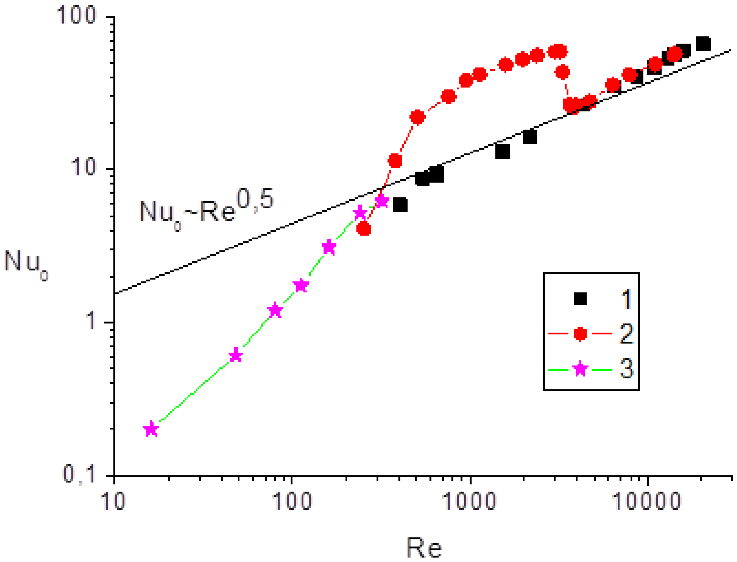
Comparison of heat transfer in an impact jet for different jet sources (tube and confuser) is presented in Figure 7 as a dependence Nu0 = f(Re) for the same parameters (d = 3 mm, h/d = 20). For comparison, the solid line in the same figure shows the correlation dependence Nu0 = 5.25Re0.5Pr0.33(h/d)0.77 [33]. It is evident that heat transfer at the stagnation point increases monotonically in the case of jet flowing out of the nozzle and corresponds to the correlation Nu0 ~ Re0.5. At the same time, for an impact jet flowing out of a long tube, non-monotonic behavior of heat transfer is observed in the region of Re < 4000.
The maximum Nusselt number for the outflow from a tube corresponds to the extremum of the heat flux density Q in Figure 6. For the outflow from a tube, a significant increase in the Nusselt number (up to 300%) is observed in the range Re = 400–3800 compared to the case when the jet flows out of a nozzle. At Re > 4000, the difference in heat transfer for the two variants of jet formation (from a tube and from a nozzle) practically disappears.
At low Reynolds numbers, the data for microjets [32] demonstrate a significant difference between the experimental data and the known correlation dependence (Nu0 ~ Re0.5), characteristic of impact macrojets.
4. Conclusions
It is known that the initial conditions have a significant effect on the flow in jets [12]. It was previously shown that the initial parabolic velocity profile contributes to an increase in the coordinate of the transition to turbulence in jet flows (x/d = 100–200 - the “long-range” effect) [12,30]. At the same time, the initial profile during outflow from a profiled confuser (“top-hat” with thin boundary layers) leads to a fast transition to turbulence (x/d = 2–6) [31]. The turbulent jet section has a large expansion angle (15–26°) both for outflow from a confuser [34] and for the case of outflow from a tube [30]. For impact jets, this leads to cooling of a large area and a more uniform distribution along the radius of the obstacle. Thus, the effect of heat exchange localization at distances (h/d > 4–6) for the outflow from confusers is not achieved. A large value of the coordinate of the transition to turbulence for the outflow from a long tube [12] allows the formation of a laminar impact jet with a small expansion angle, which creates a more compact thermal interaction with the barrier in space. As a result, the heat flux value at the stagnation point in section B–C is higher than in section D–E (see Figure 6). The presence of a puff-type superstructure in the jet increases the opening angle to values corresponding to a turbulent jet. In this case, the toroidal vortex near the surface, characteristic of the inflow of laminar jets, is significantly deformed (see Figure 5), and the velocity on the jet axis decreases, which leads to a decrease in heat transfer at the stagnation point.
However, the maximum value of the heat flux (Figure 1 point C) or the Nusselt number (Figure 3) for the outflow from a long tube corresponds to the region of laminar-turbulent transition. Thus, the maximum heat transfer does not correspond to the initial Poiseuille profile. It is known that the laminar-turbulent transition in pipes occurs through the intermittency mechanism, when large-scale vortex structures (puff) are formed [19]. For this experiment (Figure 1 point C), the percentage of turbulent structures is approximately 10%. The effect of such large-scale structures on heat transfer requires further study. The above-described mechanism of heat transfer localization is apparently similar for both round and flat gas jets, since the “long-range” effect [12,30] is present in both cases. Another promising direction is the extension of this mechanism to the processes of momentum and mass transfer. The results obtained in the work can be useful in designing promising thermal apparates.
The results obtained in the work can be useful in designing promising thermal apparatuses.
Funding
This research was funded by the Russian Science Foundation grant No. 23-29-00584.
Nomenclature
d – tube diameter, mm
f – frequency, Hz
h – distance from tube to obstacle, mm
L – tube length, m
l – puff length, m
Nu0 = αd/λ – Nusselt number in stagnation point
Q' – instantaneous value of heat-flux density, W/m2
Q – average value of heat-flux density, W/m2
q – root-mean-square value of heat flux density, W/m2
r – radial coordinate, mm
Re = Ud/ν - Reynolds number
t – time, s
T – instantaneous value of temperature, o C
Tj – temperature of impact jet gas, o C
Tw – wall temperature, oC
T1 – dimensionless temperature
Tu = u/Um × 100% –turbulence level, %
U – bulk gas velocity in the tube, m/s
Um – axial gas velocity at the tube outlet, m/s
Ux – velocity component in streamwise direction, m/s
Ur – velocity component in radial direction, m/s
u – root-mean-square value of the longitudinal component of the velocity pulsation, m/s
x – longitudinal coordinate, mm
α – average value of heat transfer coefficient, W/m2K
α' – root-mean-square value of heat transfer coefficient, W/m2K
γ – intermittency factor
λ – thermal conductivity, W/mK
ν – kinematic viscosity, m2/s
References
- Kim, S.; Jeong, M.; Lee, J. W.; Kim, S. Y.; Choi, C. K.; Kang, Y. T. Development of nanoemulsion CO2 absorbents for mass transfer performance enhancement. Int. Comm. Heat and Mass Trans. 2018, 94, 24–31. [Google Scholar] [CrossRef]
- Martin, K. Heat and mass transfer between impinging gas jets and solid surfaces. Adv. Heat Transfer 1977, 13, 1–60. [Google Scholar] [CrossRef]
- Dyban, E.; Mazur, A. Convective heat transfer in jet flow around bodies; Nauk. Dumka: Kyev, USSR, 1982; p. 303. (in Russian) [Google Scholar]
- Zuckerman, N.; Lior, N. Jet Impingement Heat Transfer: Physics, Correlations, and Numerical Modeling. Adv. Heat Transfer. 2006, 39, 565. [Google Scholar] [CrossRef]
- Liu, T.; Sullivan, J.P. Heat Transfer and Flow Structure in an Excited Circular Impinging Jet. Int. J. Heat Mass Transfer. 1996, 39, 3695–3706. [Google Scholar] [CrossRef]
- Lemanov, V.V.; Pakhomov, M.A.; Terekhov, V.I.; Travnicek, Z. Non-Stationary Flow and Heat Transfer in a Synthetic Confined Jet Impingement. Int. J. Thermal Sci. 2022, 179, 107607. [Google Scholar] [CrossRef]
- Carlomagno, G.M.; Ianiro, A. Thermo-fluid-dynamics of submerged jets impinging at short nozzle-to-plate distance: A Review. Exp. Thermal Fluid Sci. 2014, 58, 15–35. [Google Scholar] [CrossRef]
- Reynolds, A.J. Observations of a liquid-into-liquid jet. J. Fluid Mech. 1962, 14, 552–556. [Google Scholar] [CrossRef]
- Takeno, T.; Kotani, Y. Transition and structure of turbulent jet diffusion flames. Prog. Astronaut. Aeronaut. 1978, 58, 19–35. [Google Scholar] [CrossRef]
- Dubnishchev, Y. N.; Arbuzov, V. A.; Lukashov, V. V.; Sharov, K. A.; Lemanov, V. V. Optical Hilbert Diagnostics of Hydrogen Jet Burning. Optoelectron. Instrument. Proc. 2019, 55, 16–19. [Google Scholar] [CrossRef]
- Gau, C.; Shen, C. H.; Wang, Z. B. Peculiar phenomenon of micro-free-jet. Phys. Fluids 2009, 21, 092001. [Google Scholar] [CrossRef]
- Aniskin, V. M.; Lemanov, V. V.; Maslov, N. A.; Mukhin, K. A.; Terekhov, V. I.; Sharov K., A. An Experimental Study of the Flow of Subsonic Flat Mini and Micro Air Jets. Tech. Phys. Lett. 2015, 41, 46–49. [Google Scholar] [CrossRef]
- Lemanov, V.V.; Terekhov, V.I.; Sharov, K. A. Investigation of the flow in free and impinging air micro- and macrojets. Springer Proc. Phys. 2016, 185, 29–35. [Google Scholar] [CrossRef]
- Batchelor, G.K.; Gill, A.E. Analysis on the stability of axisymmetric jets. J. Fluid Mech. 1962, 14, 529–551. [Google Scholar] [CrossRef]
- Mullyadzhanov, R.; Yavorsky, N.; Oberleithner, K. Linear stability of Landau jet: non-parallel effects. J. Phys.: Conf. Ser. 2019, 1268, 012050. [Google Scholar] [CrossRef]
- Nair, A.B..; Deohans, A.; Vinoth, B.R. Global oscillations in low-density round jets with parabolic velocity profiles. J. Fluid Mech. 2022, 941, A44. [Google Scholar] [CrossRef]
- Lemanov, V. V.; Terekhov, V. I.; Sharov, K. A.; Shumeiko, A. A. An Experimental Study of Submerged Jets at Low Reynolds Numbers. Tech. Phys. Lett. 2013, 39, 421–423. [Google Scholar] [CrossRef]
- Mair, M.; Bacic, M.; Chakravarthy, K.; Williams, B. Jet preferred mode vs shear layer mode. Phys. Fluids 2020, 32, 064106. [Google Scholar] [CrossRef]
- Avila, K.; Moxey, D.; Lozar, A.; Avila, M.; Barkley, D.; Hof, B. The onset of turbulence in pipe flow. Science 2011, 333, 192–196. [Google Scholar] [CrossRef]
- Nikitin, N.; Pimanov, V. Sustainment of Oscillations in Localized Turbulent Structures in Pipes. Fluid Dyn. 2018, 53, 65–73. [Google Scholar] [CrossRef]
- Hussain, A.K.M.F. Coherent structures and turbulence. J. Fluid Mech. 1986, 173, 303–356. [Google Scholar] [CrossRef]
- Brown, G.L.; Roshko, A. On density effects and large structure in turbulent mixing layers. J. Fluid Mech. 1974, 64, 775–816. [Google Scholar] [CrossRef]
- Holmes, P.; Lumley, J.L.; Berkooz, G.; Rowley, C.W. Turbulence, Coherent Structures, Dynamical Systems and Symmetry, 2nd ed.; Cambridge University Press: Cambridge, UK, 2012; p. 386. [Google Scholar] [CrossRef]
- Wygnanski, I.J.; Champagne, F.H. On transition in a pipe. Part 1. The origin of puffs and slugs and the flow in a turbulent slug. J. Fluid Mech. 1973, 59, 281–335. [Google Scholar] [CrossRef]
- Lemanov, V.; Lukashov, V.; Sharov, K.; Nezavitin, D. Turbulent spots in the flame of a diffusion torch. J. Phys. Conf. Ser. 2019, 1382, 012058. [Google Scholar] [CrossRef]
- Lemanov, V.; Lukashov, V.; Sharov, K. Turbulent superstructures in inert jets and diffusion jet flames. Fluids 2021, 6, 459. [Google Scholar] [CrossRef]
- Lemanov, V.; Terekhov, V. Specific features of heat transfer at the stagnation point of an impact axisymmetric jet at low Reynolds numbers. High Temp. 2016, 54, 454–456. [Google Scholar] [CrossRef]
- Mityakov, A.V.; Sapozhnikov, S.Z.; Mityakov, V.Y.; Snarskii, A.A.; Zhenirovsky, M.I.; Pyrhonen, J.J. Gradient heat flux sensors for high temperature environments. Sens. Actuators 2012, A 176, 1–9. [Google Scholar] [CrossRef]
- Sapozhnikov, S.Z.; Mityakov, V.Yu.; Mityakov, A.V. Heatmetry. The science and practice of heat flux measurement; Springer: Cham, Switzerland, 2020; p. 209. [Google Scholar] [CrossRef]
- Lemanov, V.; Lukashov, V.; Sharov, K. Transition to Turbulence through Intermittence in Inert and Reacting Jets. Fluid Dyn. 2020, 55, 768–777. [Google Scholar] [CrossRef]
- Ho, C.M.; Huerre, P. Micro-electro-mechanical-systems (mems) and fluid flows. Annu. Rev. Fluid Mech. 1984, 16, 579–612. [Google Scholar] [CrossRef]
- Chang, C.J.; Chen, H.; Gau, C. Transfer of a Micro Jet Impinging on a Heated Chip: Part I— Micro Free and Impinging Jet Flow. Nanosecond Microsc. Thermophys. Eng. 2013, 17, 50–68. [Google Scholar] [CrossRef]
- Judaev, B.N.; Mikhailov, M.S.; Savin, V.K. Heat transfer during the interaction of jets with obstacles; Mashinostroenie: Moskow, USSR, 1977; p. 248. (in Russian) [Google Scholar]
- Ginevsky, A.S.; Vlasov, Y.V.; Vlasov, E.V.; Karavosov, R.K. Acoustic control of turbulent jets; Springer: Berlin, Germany, 2004; p. 232. [Google Scholar] [CrossRef]
Figure 1.
The test setup for PIV measuring of puff structures dynamics in an impinging jet.
Figure 2.
The setup for measuring heat transfer between an obstacle and an impinging jet in the presence of puff structures in the jet.
Figure 2.
The setup for measuring heat transfer between an obstacle and an impinging jet in the presence of puff structures in the jet.
Figure 3.
Time series of a single puff velocity in the mixing layer at a distance of r = 4 mm (a) and r = 3 mm (b) from the axis and on the axis (r = 0) (c) in cross-section x = 60 mm (СО2), Re = 2400. t1 = 0.688 s; t2 = 0.702 s; t3 = 0.72 s.
Figure 3.
Time series of a single puff velocity in the mixing layer at a distance of r = 4 mm (a) and r = 3 mm (b) from the axis and on the axis (r = 0) (c) in cross-section x = 60 mm (СО2), Re = 2400. t1 = 0.688 s; t2 = 0.702 s; t3 = 0.72 s.
Figure 4.
Instantaneous velocity field (a) at the passage of the trailing edge of the puff superstructure; instantaneous vorticity field (b) corresponding to the velocity field (a); CO2, d= 8 mm, Re = 2400.
Figure 4.
Instantaneous velocity field (a) at the passage of the trailing edge of the puff superstructure; instantaneous vorticity field (b) corresponding to the velocity field (a); CO2, d= 8 mm, Re = 2400.
Figure 5.
The pattern of average flow streamlines the (a) when a CO2 jet impinges on an obstacle; the pattern of streamlines of the instantaneous velocities field (b) when passing through a puff superstructure in the jet (d=8 mm, h=65 mm, CO2, γ = 0.5 and Re = 2462).
Figure 5.
The pattern of average flow streamlines the (a) when a CO2 jet impinges on an obstacle; the pattern of streamlines of the instantaneous velocities field (b) when passing through a puff superstructure in the jet (d=8 mm, h=65 mm, CO2, γ = 0.5 and Re = 2462).
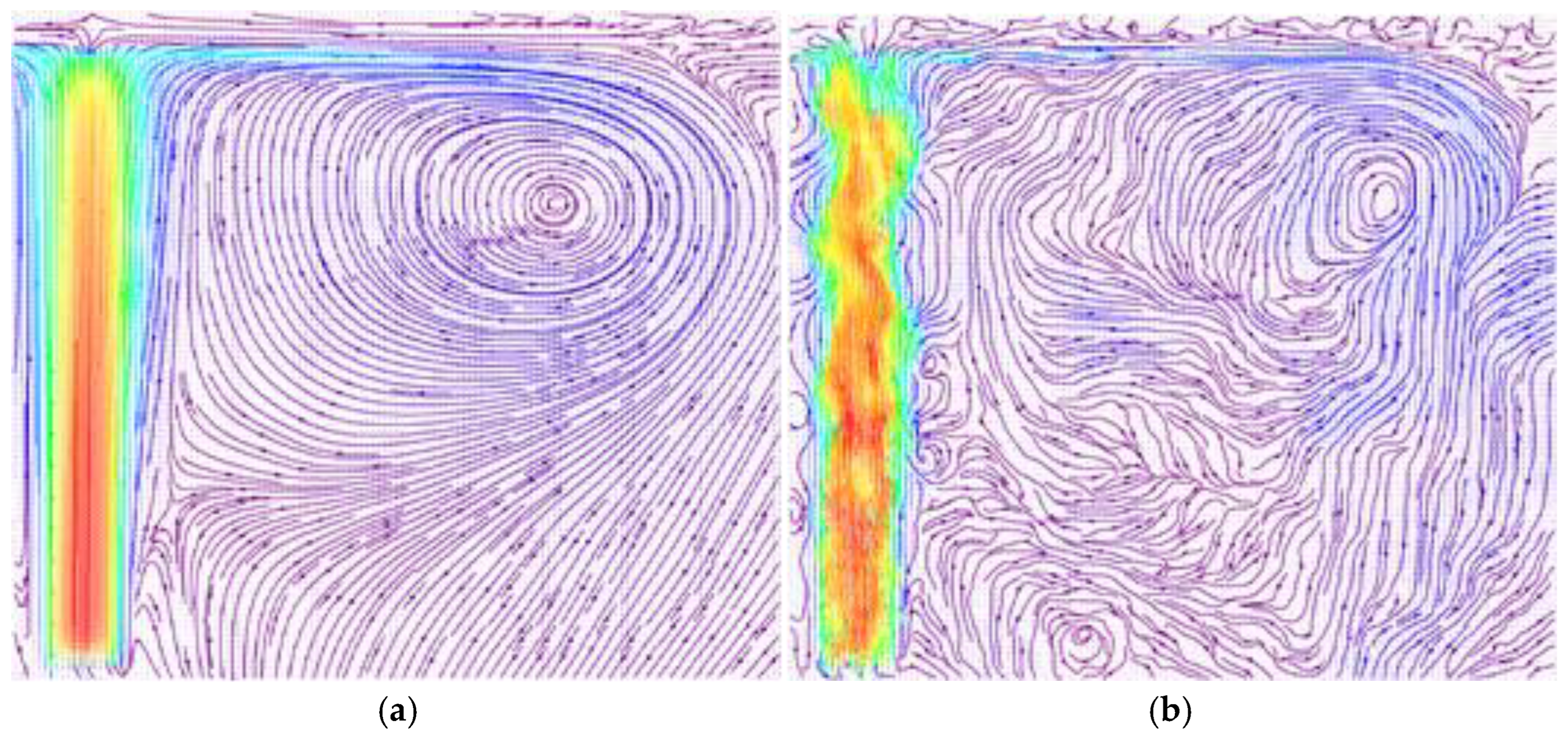
Figure 6.
Dependence of the average and pulsation value of heat flux density, degree of turbulence on the Re number.
Figure 6.
Dependence of the average and pulsation value of heat flux density, degree of turbulence on the Re number.
Disclaimer/Publisher’s Note: The statements, opinions and data contained in all publications are solely those of the individual author(s) and contributor(s) and not of MDPI and/or the editor(s). MDPI and/or the editor(s) disclaim responsibility for any injury to people or property resulting from any ideas, methods, instructions or products referred to in the content. |
© 2024 by the authors. Licensee MDPI, Basel, Switzerland. This article is an open access article distributed under the terms and conditions of the Creative Commons Attribution (CC BY) license (http://creativecommons.org/licenses/by/4.0/).
Copyright: This open access article is published under a Creative Commons CC BY 4.0 license, which permit the free download, distribution, and reuse, provided that the author and preprint are cited in any reuse.


