
Submitted:
12 June 2023
Posted:
12 June 2023
You are already at the latest version
Abstract
The transition towards a CO2 neutral industry is currently spurring many new developments regarding processes for the conversion of CO2, or CO2-rich streams, into platform molecules such as methanol and dimethyl ether (DME). New processes give rise to new separation challenges, as well as novel opportunities for joint optimization of reaction and separation. In this context, the separation of CO2 and DME can be performed very efficiently using the newly developed concept of Stripping Enhanced Distillation (SED). SED is a distillation process that utilizes an additional stripping component (clearing gas) to promote the separation in the column. SED benefits from the utilization of the feedstock components as a clearing gas that can afterwards be recycled back to the conversion unit with the vapor distillate. Strongly improving the separation performance in the column, this approach also removes the need for external stripping mediums and in addition this recycle approach may significantly reduce the demand on the conversion unit upstream of SED. The benefits of using SED are demonstrated for two different processes for DME synthesis: (i) CO2 – DME separation after the Sorption Enhanced DME Synthesis (SEDMES) process, using hydrogen as clearing gas, and (ii) CO2 – DME separation after direct DME synthesis via dry reforming (DIDR), using methane as clearing gas. For the different cases, it is shown that, with minimal adaptations, the energy consumption for distillation is reduced by 20-30%, while product losses are minimized at the same time.
Keywords:
Distillation
; Stripping
; DME purification
; SEDMES
; Carbon dioxide
; Stripping enhanced distillation
1. Introduction
The rising global needs for the reduction of greenhouse gas emissions has prompted the development of alternative and sustainable applications in the industry and society in general. Carbon capture and utilization (CCU) technologies are among the necessary tools towards carbon circularity of the industry [1,2,3]. Technologies such as synthesis of methanol (MeOH) and dimethyl ether (DME) brings the CCU benefits to the front, allowing the direct utilization of CO2 towards a sustainable alternative fuel and chemical feedstock [4,5]. It is noteworthy to mention that DME has become a molecule of interest because of its notable properties such as being a non-corrosive, non-carcinogenic, non-toxic colorless gas, environmentally friendly and easy to liquefy [6]. These properties make DME usable in various applications either as a building block for higher carbon molecules or as end use product; green aerosol propellant that can replace the hazardous chloro-fluoro-carbons (CFC) or substituent for petroleum-based diesel fuel (cetane numbers varies between 55 and 60) [7] or in combustion cells. In the latter applications - DME as a clean fuel- it produces minimal NOx and CO and no SOx emissions. Besides, due to its high oxygen content it leads to soot-free combustion [8]. Moreover, DME can be blended up to 20-30% with LPG for its replacement for domestic and transportation usage.
Conventionally, DME is produced in the two-step method that includes synthesis of methanol from syngas (a mixture of CO, H2 and CO2) over copper-based catalysts and the subsequent dehydration step over solid acid catalysts such as γ-alumina, HZSM-5, silica-alumina and fluorinated alumina. The industrial standard for methanol dehydration takes place in a fixed-bed catalytic reactor, followed by downstream processing using distillation to deliver highly pure DME (> 99.99wt%). The conventional distillation separation process for purification of DME and recovery of unconverted methanol is still state of the art, but can be outperformed by dividing wall column distillation [9] or even reactive distillation: process intensification by integration of the methanol dehydration reaction with the separation of the DME product [10].
The key opportunity in DME production is the flexibility of utilizing various feedstocks. The stretch of the process comes partially from its base mixture; syngas. It can be either biomass-based or from different fossil-based raw materials such as oil, naphtha, coal (bed methane), shale gas or natural gas. Moreover, hydrogenation of the captured CO2 using renewable hydrogen has currently become an interesting topic in circular industry, which is forecasted to play a key role in the energy transition. In fact, the CO2 recycling to methanol and subsequently to DME has been thoroughly discussed by George Olah [11] where he prescribes its key role in what he has coined the methanol economy. Therefore, DME can be called a multisource and multipurpose molecule that is future proof.
In the pursuit of finding innovative methods for DME production, one of the research lines is the direct or the one-step conversion of the syngas to DME in a single reactor. Other research studies focused on using reactive distillation for the dehydration of methanol to DME in one column and the subsequent distillation for the recovery of methanol. Moreover, in a reactive-dividing-wall column methanol is fed to the reactive zone where a heterogenous catalyst is incorporated. The DME is separated as top distillate, water leaves the column as bottom product and the methanol as a side product that is ideally recycles without further purification [8].
Methane dry reforming is a well-established procedure for production of syngas [12,13,14]. Subsequent conversion of syngas to MeOH and/or DME is strongly correlated with the ratio of H2/CO. MeOH conversion requires H2/CO ratios of 2, while direct DME synthesis from syngas can be performed at ratios of approximately 1 [15]. Synthesis of DME from syngas produced from methane is represented by the following catalytic reactions:
Reaction (1) is dry reforming of methane, (2a) and (2b) are the synthesis of methanol from CO2 and CO, respectively, (3) is the water-gas shift reaction, (4) is DME synthesis from methanol dehydration and (5) is the direct conversion of syngas into DME.
Novel DME synthesis routes, such as DME synthesis integrated with dry reforming (DIDR) and Sorption Enhanced DME synthesis (SEDMES) are examples of effective direct DME synthesis routes. DIDR process consists of initial dry or tri-reforming of natural gas (i.e. reaction of methane with CO2, O2 and H2O) to produce syngas that is directly converted into DME in a single reactor [12,16,17].
SEDMES process on the other hand allows for a direct conversion of CO2 (6) in a multicolumn adsorption system in which water is removed in situ. In this process two commercially catalysts and an adsorbent material are applied: CZA for MeOH synthesis, γ-alumina for dehydration of MeOH and LTA 3A solid adsorbent for the in-situ removal of water [18,19,20]. This selective H2O adsorption shifts the reaction equilibrium towards higher reactant conversion and increased DME production.
Both conversion routes yield a DME product that requires further processing, which typically comprises several distillation steps. The most difficult separation task in this case comes within the first distillation step where CO2 and residual gases are separated from DME and heavier components (mainly H2O and MeOH). The difficulty in separating CO2 from DME comes from the high affinity of the two components and the proximity and the shape of their VLE curves within a full pressure spectrum in the Henry’s law region (see Figure 1).
The technological developments in a conversion domain exemplified by SEDMES and DIDR, facilitate the development and conjoint optimization with the purification techniques. Stripping enhanced distillation (SED) presents such a development, whereby combining two established methods, distillation and stripping to improve the separation efficiency and reduce the capital and operating costs. In this study, the advantages of using SED in two different processes for direct DME synthesis are shown: (i) CO2 – DME separation after the Sorption Enhanced DME Synthesis (SEDMES) process utilizing hydrogen as stripping gas, and (ii) CO2 – DME separation after direct DME synthesis utilizing methane as stripping gas. In case (i) the impact of column design parameters such as reflux ratio and number of equilibrium stages on minimizing the energy consumption and product losses was studied. Moreover, in case (ii) a sensitivity analysis was carried out with variables; the flow rate of the stripping agent and the reflux ratio in the SED column for the same aim; minimizing the energy consumption and product losses. For the studied cases it is demonstrated that with minor changes to the existing facilities, introducing SED reduces energy consumption and cuts down the product losses.
2. SED Method and Application
Stripping enhanced distillation (SED) is a distillation process that utilizes a gaseous component, either inert or (preferably) a feedstock constituent, as a stripping medium to increase the separation efficiency comparatively to the conventional routes. The stripping medium or clearing gas, needs to have low affinity towards the heavy component or the bottom product of the distillation process.
SED implementation into the process benefits from the integration of the feedstock and the downstream recycle stream of the unconverted gaseous components to the conversion unit. First, it removes the requirements for the addition of an external stripping medium, as the clearing gas will be obtained directly from the feedstock. Second, by using the feedstock component, the vapor distillate which primarily consists of unreacted components can be recycled to the conversion unit. Third, it can reduce the conversion demands on the reaction unit. This is due to the multi-pass approach of the uncovered components, the demand for the existing system but also design requirements can be reduced.
3. Process Simulation
The Stripping enhanced distillation concept was evaluated in Aspen Plus simulator (V10 and V12). The thermophysical properties of the components involved (e.g. DME, MeOH, CO2 CO, H2 and H2O) are available in the Aspen Plus database. The process simulations are solved in the sequential modular mode. In order to sufficiently describe the physical interaction inside the DME mixtures, more specifically CO2 – DME and CO2 – H2O, several thermodynamic models were tested to describe their vapor-liquid-equilibria (VLE). The model predictions were compared to the experimental data available in the open literature [21,22] to verify the reliability of the simulation results. The predictive Soave-Redlich Kwong equation of state (PSRK EoS) provided highest level of matching with the experimental data (see Figure 1), and was adopted as a default method for future simulation and analysis. The PSRK EoS combines the UNIFAC model and the Huron-Vidal mixing rules with the SRK EoS. The merit of this combination is that it allows prediction of the VLE data over a notable larger pressure and temperature ranges than the UNIFAC model and can be applied for mixtures containing supercritical compounds [23].
The rigorous (RadFrac) fractionation module was utilized as a primary tool in the evaluation of stripping enhanced distillation and in comparative studies with the conventional methods. RadFrac is a rigorous model for simulating multistage vapor-liquid fractionation operation. In the conventional approach the feed from the DME synthesis reactor is first led via a heat exchanger to a flash vessel to primarily remove H2 and CO. However, moderate losses of DME and CO2 are encountered. Afterwards the bottom stream of the flash drum is sent to the distillation column where a CO2 rich stream is obtained as the distillate, while the bottom stream containing a mixture of DME, MeOH and H2O is sent to the subsequent distillation column. There DME is further purified to meet the set purity objective (e.g. > 98.5wt%). Unlike the conventional methods, the SED is an intensified process where distillation and gas stripping are combined in one unit. This allows for an efficient separation in one operation section, making the flash tank and the heat exchanger, that would be required in the conventional process, redundant, see Figure 2. The SED column was designed with two inlets. The feed enters the column around the middle point of the column, while the striping gas enters the column below the bottom tray. The column’s bottoms primarily consists of DME and residual MeOH and H2O. The top product leaving the column contains mainly CO2, unconverted gases and the stripping gas.
The goal of this study was to design a column that meets a specific product purity according to international standards for DME as a fuel (ISO 16861:2015(E) Fuel class F), production capacity that reaches the scale of a demonstration plant and reduction of product losses. The basis of the simulation was a product flow rate of 100 kmol∙hr-1 from a DME synthesis reactor. Tools like design specs, calculator blocks and sensitivity analysis were applied in order to find optimal design conditions for the abovementioned constraints. The DME purity and the maximum allowed impurities are listed in

Table 1.
DME product purity was based on the ISO fuel spec (ISO 16861:2015(E) Fuel class F).
| Specifications | Limit (wt%) |
|---|---|
| DME purity | >98.5 |
| CO2 in the product | <0.1 |
| Hydrocarbons (mainly CH4) in the DME product | <1 |
Moreover, the SED and the conventional separation processes were compared on the basis of energy consumption, the DME losses, the number of equilibrium stages and the required reflux ratio. The distillate rate was fixed in all cases. The aforementioned parameters are co-dependent, hence the results should be evaluated cumulatively. Typical compositions of the SEDMES and DIDR product streams are listed in Table 2.
3.1. Case (i): CO2 – DME Separation after the Sorption Enhanced DME Synthesis (SEDMES) Process Utilizing Hydrogen as Clearing Gas
The SEDMES process enables utilization of industrial carbon in conjunction with hydrogen in a direct CO2 – DME synthesis route. This is done during the cyclic operation in the multicolumn reactive-adsorption and regeneration system. During a single cycle each of the columns continuously go through the different steps of the SEDMES cycle consecutively (i.e. adsorption, blowdown, purge and repressurization). Initially CO2 and H2 are fed to the column during the reactive adsorption step producing DME, while H2O is selectively adsorbed shifting the equilibrium towards higher DME production. Subsequently, steam saturated column is regenerated by feeding a purge gas, repressurized/depressurized for a pressure swing cycle, or heated/cooled for a temperature swing regeneration. This complex behavior, characteristic to sorption enhanced processes, requires a detailed approach to design and system optimization. Therefore, a robust downstream section with the recycle can reduce the design requirements and further optimize the system. Moreover, the high temperature and pressure SEDMES product stream requires an extensive treatment in order to obtain highly pure DME. Conventionally, the SEDMES product purification consists of three steps, see Figure 3. Initially, the bulk of residual gasses is removed in the flash vessel. This primarily includes H2 and CO, part of CO2 is also removed with small DME losses. Following the flash vessel, the DME – CO2 distillation column is utilized to remove the CO2 from the mixture of DME, water and methanol. A second distillation column is used to obtain pure DME as the distillate product. The bottom products of the second column consists of water and methanol.
Stripping enhanced distillation enables single step separation of DME and CO2 (and other unconverted gases) coming from the SEDMES multicolumn system, see Figure 4. The column consists of two feed intakes, one for the SEDMES DME product and other one for the hydrogen stripping gas. The DME product stream enters the column around the middle section, depending on the separation requirements of the column. The hydrogen feed is entering below the bottom stage of the column and can be supplied in several ways. In the larger SEDMES infrastructure, an electrolyser unit will provide the H2 as a feed for the SEDMES unit and stripping gas for the SED column.
In this case study, two different SEDMES product streams with high and low CO2 content were investigated, see Table 2. The difference in composition can be explained with the conversion degree of CO2. Simulations were run at different pressures (i.e. 15, 20, 30 and 50 bar). The column size, the reflux ratio and the amount of required H2 stripping gas were varied independently to fulfill the requirements set in Table 1. Aforementioned parameters were used as a basis of comparison between SED and the conventional process under the same process conditions and feed composition
3.2. Case (ii): CO2 – DME Separation after direct DME Synthesis via Dry Reforming Utilizing Methane as Clearing Gas
In the conventional DIDR process, the tri-reformer is used for the reaction of natural gas with steam, carbon dioxide and oxygen to produce syngas with the correct H2:CO ratio, see Figure 5. The unreacted and by-product CO2 is removed via absorption using chilled methanol and recovered in the stripper before recycling it to the tri-reformer. Moreover, the methanol absorber is also used to remove water from the syngas before feeding it to the DME reactors. Direct DME synthesis in the DIDR process (via reaction 5) produces equimolar amounts of DME and CO2. Furthermore, due to the thermodynamic limitations, the downstream separation results in large recycle streams. After the DME synthesis, the purification train separates and recycles the syngas to the DME reactor, separates the CO2 and directs it back to the reformer and removes the by-product methanol to obtain a product stream with predefined purity.
Similarly to the SEDMES process, the DIDR stripping enhanced distillation enables efficient separation of DME and CO2 and other unconverted gases. Substitution of the downstream CO2 separation column (removal of CO2 from the DME product stream) with SED, allows for a more efficient purification while using methane as clearing gas. The SED column consists of two feed intakes, one for the DIDR DME product stream and the other one for the methane stripping gas, see Figure 6. The DME product stream enters the column around the middle section, depending on the separation requirements of the column. The methane feed enters at the bottom stage of the column. Part of the methane that is used as clearing gas in the SED will be recycled with unconverted gasses and CO2 to the reformer unit where it is converted to syngas again. The composition of the DME product stream of a pilot scale DIDR reactor [24] is listed in Table 2. We have assumed that 95mol% of the syngas is recovered using a knock-out vessel and recycled to the reactor prior to the CO2- DME separation.
In this case study a sensitivity analysis was performed where the reflux ratio (range 0.2-3) and the flowrate of the methane stripping gas (0-20 kmol∙h-1, 0 means no SED was utilized) were varied. The number of equilibrium stages was fixed at 12. Lower number of stages resulted in higher DME losses (>1wt%).
4. Results and discussion
In order to compare the simulation results for the two cases mentioned in section 3, the feed composition and the operational conditions of the product streams leaving the reactor are kept constant. The synthesis step is out of scope of this study. Instead, the focus is on the separation of the gases and the final purification of the DME from the condensables (i.e. methanol and water) to meet the predefined specifications.
As discussed, in DME purification following direct DME synthesis, the most difficult separation is between CO2 and DME. This is because CO2 dissolves very well in liquid DME (cf. Figure 1). The concept of SED is based on the introduction of a light gas that does not readily dissolve in the heavy product DME. Specifically, hydrogen and methane are introduced into the system, because they both allow easy recycling to the upstream synthesis section. By the introduction of the additional light component, the partial pressure of light product CO2 is reduced and the lower quantities are dissolved in the liquid DME. The clearing gas is readily recovered at the top of the distillation column together with the other light components (H2, CO, CO2, CH4) while heavy components (DME, methanol, water) are recovered as the bottom product. The concept thus gives rise to some very favorable characteristics in the distillation process, as described below for the two use cases.
4.1. Case (i): CO2 – DME Separation after the Sorption Enhanced DME Synthesis (SEDMES) Process Utilizing Hydrogen as Clearing Gas
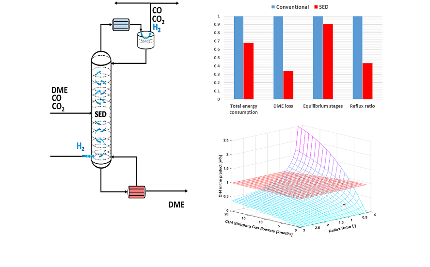
A qualitative comparison of the performance of SED and conventional purification of the SEDMES product stream is presented in Figure 7 and listed in Table 3. For the sake of completion both feed compositions listed in Table 2 are investigated. In addition, the values of the conventional process are normalized. As mentioned before, the presented process parameters are interconnected and should be evaluated as such. As it can be seen from the obtained results, the SED performance significantly exceeds that of the conventional process for all the parameters:
- Reflux ratio – Intensified stripping effect of H2 clearing gas results in a reduction of reflux flow requirements;
- Total energy consumption – SED implementation results in moderately to significantly lower energy consumption (up to 30% circa 200 - 800 kW case dependant) due to reduced fluid loads on the column because of intensified H2 stripping activity and the lack of flash vessel energy requirements;
- Total DME losses – Even though both processes were optimized, the reduction of DME losses in conventional process is a challenging task due to the presence of the non-selective flash vessel. On the other hand SED process can achieve minimal DME losses.
- Equilibrium stages – Due to the stripping effect of the clearing gas, the SED process requires lower number of equilibrium stages.
4.2. Case: (ii) CO2 – DME Separation after Direct DME Synthesis via Dry Reforming Utilizing Methane as Clearing Gas
In this process, methane and CO2 are combined with a recycled stream of methane in the reformer. The recycle stream of methane comes from the off gas of the condenser on top of the SED column, see Figure 6. In the case of using a tri-reformer, the streams are further combined with steam before entering the burner of the tri-reformer. Using the DME product stream listed in Table 2, a process simulation of the SED column using steady state models is conducted in Aspen Plus. The simulation reflects the results of real operation data of a demo scale plant [24]. Moreover, the presence of the tri-reformer in the DIDR process adds an additional degree of freedom to the choice of the clearing gas. One could think of using oxygen or nitrogen instead of methane. However, preliminary results showed that using oxygen led to high concentrations of oxygen in the gas stream (~41 wt%) and contamination above (~1 wt%) the max allowed limit in DME as fuel. To meet the product specifications, oxygen adds complexity to the process layout in terms of CAPEX (e.g. more stages) and OPEX (e.g. higher reflux ratio) in addition to safety precautions. Using nitrogen on the other hand, contaminates the DME stream (~0.4 wt%) and the gas stream is diluted with nitrogen (~40 wt%) requiring additional operational steps for nitrogen removal. The best option in this case is still using methane as stripping gas; methane is both feed to the reformers and is a functional clearing gas. The clearing gas along with other unconverted gases is recycled to the reformer with a small purge to avoid accumulation of inert gases. Moreover, from the sensitivity analysis can be concluded that using SED leads to:
- Reduction in the total energy consumption compared to the conventional;
- A drop in the reflux ratio of ~30%;
- The stripping gas flow rate is an additional variable to ensure the DME purity meets the specified product purity, ISO 16861:2015(E).
The results of the sensitivity analysis are shown in Figure 8. The red surface in the figures denotes the design boundaries of the system, i.e. the DME purity, CH4 and CO2 content in the product as given in Table 1. Cases where all the design boundaries are satisfied were compared with the conventional distillation in terms of energy consumption, and the optimal SED case was chosen. The optimal parameters for the SED column are represented by the red circle in figures Figure 8. Moreover, their numerical values, along with those for conventional distillation, are listed in Table 4.
5. Conclusions
Stripping enhanced distillation is a novel application in the separation of CO2 and DME. CO2 utilization as a carbon source for synthesis of valuable products that are conventionally produced from fossil fuels plays an important role in the energy transition. Due to thermodynamic limitations of CO2 conversion to DME, the product stream tends to contain substantial amounts of CO2. The high affinity of CO2 towards DME complicates the purification step. The concept of SED relies on the introduction of an additional light component (e.g. H2, CH4) into the distillation column in order to facilitate the separation, resulting in significant operating cost savings. This is in part due to the configuration of the process, as the stripping gas hydrogen is readily available for the reduction of CO2 to DME. In addition, the vapor distillate which now includes the stripping gas does not need to be further purified but it can be directly recycled to the conversion unit after a small purge stream.
In this work, the results of two distinct case studies of the SED performance are presented; (i) SEDMES process, using hydrogen as clearing gas and (ii) dry reforming process (DIDR) utilizing methane as clearing gas. In general, addition of the stripping gas allows for the reduction of reflux ratio in both cases compared to the conventional process. This can be ascribed to the higher stripping effect, which directly influences the column load and consequently the required reflux ratio necessary for the desired purity. Similarly, the number of equilibrium stages could be reduced, which is also correlated to the required reflux ratio, as increasing one value influences the reduction of the second.
In the SEDMES case study, the process simulation results show, that at all the process relevant pressures and the two compositions (related to degree of CO2 conversion) studied, reduction in the total energy consumption by around 30%, DME losses and number of required equilibrium stages is achieved.
In the DIDR case study, a sensitivity analysis of the process including SED was conducted. The reflux ratio and the flow rate of methane clearing gas were varied while the number of column equilibrium stages was fixed. By utilizing methane, purification enhancement was observed due to its stripping effect in which SED outperformed conventional distillation. Energy savings by up to about 20% were observed while maintaining desired product quality and minimizing product losses.
Acknowledgments
This project has received funding from the Dutch Ministry for Economic Affairs and Climate Policy
Conflicts of Interest
The authors declare no conflict of interest
References
- L. Desport, S. Selosse. An overview of CO2 capture and utilization in energy models, Resour. Conserv. Recycl. 180 (2022) 106150. [CrossRef]
- M. Pérez-fortes, J.C. Schöneberger, A. Boulamanti, E. Tzimas. Methanol synthesis using captured CO 2 as raw material : Techno-economic and environmental assessment, Appl. Energy. 161 (2016) 718–732. [CrossRef]
- C. Ampelli, S. Perathoner, G. Centi. CO2 utilization: an enabling element to move to a resource- and energy-efficient chemical and fuel production, Philos. Trans. R. Soc. A Math. Phys. Eng. Sci. 373 (2015). http://rsta.royalsocietypublishing.org/content/373/2037/20140177.abstract. [CrossRef]
- Kätelhön, R. Meys, S. Deutz, S. Suh, A. Bardow. Climate change mitigation potential of carbon capture and utilization in the chemical industry, Proc. Natl. Acad. Sci. U. S. A. 166 (2019) 11187–11194. [CrossRef]
- M. De Falco, M. Capocelli, G. Centi. Dimethyl ether production from CO2 rich feedstocks in a one-step process: Thermodynamic evaluation and reactor simulation, Chem. Eng. J. 294 (2016) 400–409 . [CrossRef]
- M. Müller, and U. Hübsch. Dimethyl Ether. In Ullmann's Encyclopedia of Industrial Chemistry, (2000) 305-308. [CrossRef]
- M. Alam, O. Fujita, K. Ito. Performance of NOx reduction catalysts with simulated dimethyl ether diesel engine exhaust gas. Proceedings of the Institution of Mechanical Engineers, Part A: Journal of Power and Energy. 218(2) (2004) 89-95. [CrossRef]
- A. Kiss, D. J. -P.C. Suszwalak. Innovative dimethyl ether synthesis in a reactive dividing-wall column. Computers & Chemical Engineering. 38 (2012) 74-81. [CrossRef]
- A. Kiss, R. M. Ignat. Revamping dimethyl ether separation to a single-step process. Chemical Engineering & Technology, 36(7) (2013) 1261-1267. [CrossRef]
- S. Bîldea, R. Győrgy, C. C. Brunchi, A. A. Kiss. Optimal design of intensified processes for DME synthesis. Computers & chemical engineering, 105 (2017) 142-151. [CrossRef]
- G.A. Olah, A. Goeppert, G.K. Surya Prakash. Chemical recycling of carbon dioxide to methanol and dimethyl ether: from greenhouse gas to renewable,environmentally carbon neutral fuels and synthetic hydrocarbons. J. Org.Chem. 74(2) (2009) 487–498. [CrossRef]
- W. Cho, T. Song, A. Mitsos, J.T. McKinnon, G.H. Ko, J.E. Tolsma, D. Denholm, T. Park, Optimal design and operation of a natural gas tri-reforming reactor for DME synthesis, Catal. Today. 139 (2009) 261–267. [CrossRef]
- J.B. Claridge, A.P.E. York, A.J. Brungs, C. Marquez-Alvarez, J. Sloan, S.C. Tsang, M.L.H. Green, New Catalysts for the Conversion of Methane to Synthesis Gas: Molybdenum and Tungsten Carbide, J. Catal. 180 (1998) 85–100. [CrossRef]
- E. Schwab, A. Milanov, S.A. Schunk, A. Behrens, N. Schödel, Dry reforming and reverse water gas shift: Alternatives for syngas production?, Chemie-Ingenieur-Technik. 87 (2015) 347–353. [CrossRef]
- W. Schakel, G. Oreggioni, B. Singh, A. Strømman, A. Ramírez. Assessing the techno-environmental performance of CO2 utilization via dry reforming of methane for the production of dimethyl ether. J. CO2 Utilization. 16 (2016) 138-149. [CrossRef]
- E. Rezaei, L.J.J. Catalan, Evaluation of CO2 utilization for methanol production via tri-reforming of methane, J. CO2 Util. 42 (2020) 101272. [CrossRef]
- M.T. Luu, D. Milani, M. Wake, A. Abbas, Analysis of di-methyl ether production routes: Process performance evaluations at various syngas compositions, Chem. Eng. Sci. 149 (2016) 143–155. [CrossRef]
- J. Van Kampen, J. Boon, J. Vente, M. Van Sint Annaland, Sorption enhanced dimethyl ether synthesis under industrially relevant conditions: Experimental validation of pressure swing regeneration, React. Chem. Eng. 6 (2021). [CrossRef]
- Liuzzi, C. Peinado, M.A. Peña, J. Van Kampen, J. Boon, S. Rojas, Increasing dimethyl ether production from biomass-derived syngas: via sorption enhanced dimethyl ether synthesis, Sustain. Energy Fuels. 4 (2020) 5674–5681. [CrossRef]
- G. Skorikova, M. Saric, S.N. Sluijter, J. van Kampen, C. Sánchez-Martínez, J. Boon, The Techno-Economic Benefit of Sorption Enhancement: Evaluation of Sorption-Enhanced Dimethyl Ether Synthesis for CO2 Utilization, Front. Chem. Eng. 2 (2020) 1. [CrossRef]
- P. C. Gillespie, G. M. Wilson. Gas Processors Association RR-48. (1982). No. 48, 1812 First Place, Tulsa, Okla. 74103.
- Jónasson, O. Persson, A. Fredenslund. High Pressure Solubility of Carbon Dioxide and Carbon Monoxide in Dimethyl Ether. J. Chem. & Eng. Data. 40 (1995) 296-300. [CrossRef]
- J. Gmehling. From UNIFAC to modified UNIFAC to PSRK with the help of DDB. Fluid Phase Equilibria. 107(1) (1995) 1-29. [CrossRef]
- Song, W. Cho, G. Lee, D. K. Park, E. S. Yoon. Numerical Analysis of a Pilot-Scale Fixed-Bed Reactor for Dimethyl Ether (DME) Synthesis. Ind. Eng. Chem. Res. 47(13) (2008) 4553-4559. [CrossRef]
- H. Kim, S. Kim, W. Cho, E. S. Y. Simulation of commercial dimethyl ether production plant. Comp. Aided Chem. Eng. 28 (2010) 799-804. [CrossRef]
Figure 1.
CO2 solubilities in DME [22] (left) and CO2 solubilities in H2O [21] (right); the red filled triangles are experimental data from literature and the solid lines are estimations using predictive Soave-Redlich-Kwong (PSRK) equation of state.
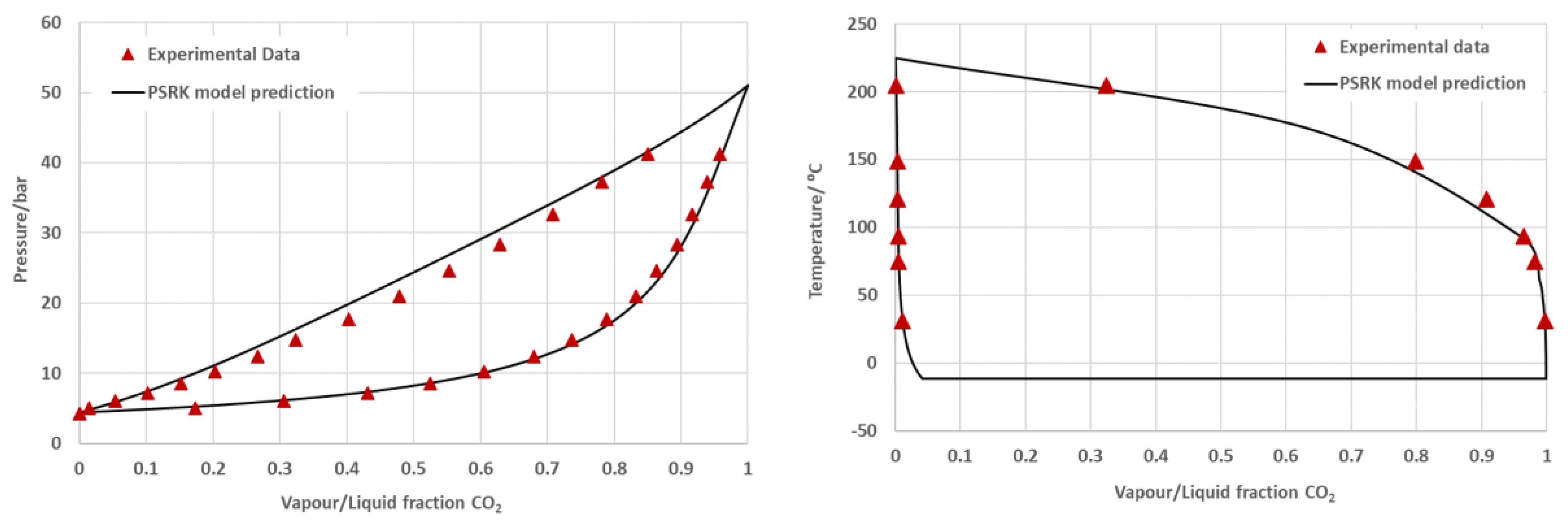
Figure 2.
The conventional process for SEDMES products separation (Left); SED process for SEDMES product separation (Right).
Figure 2.
The conventional process for SEDMES products separation (Left); SED process for SEDMES product separation (Right).
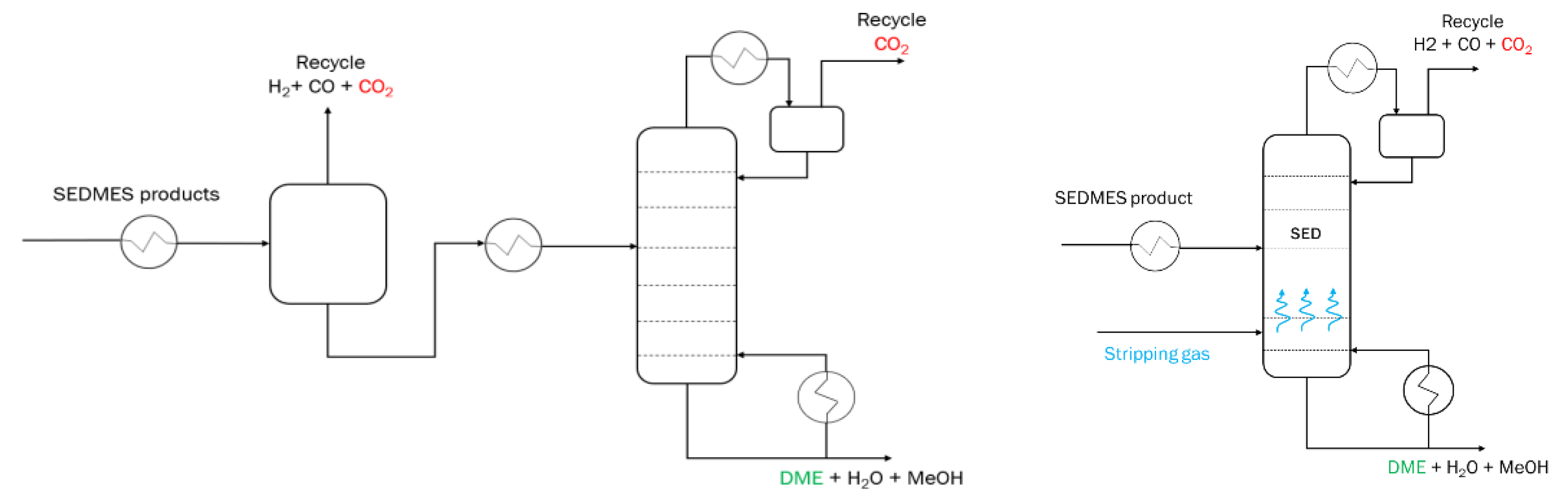
Figure 3.
The conventional SEDMES process flowsheet; DME conversion and purification.
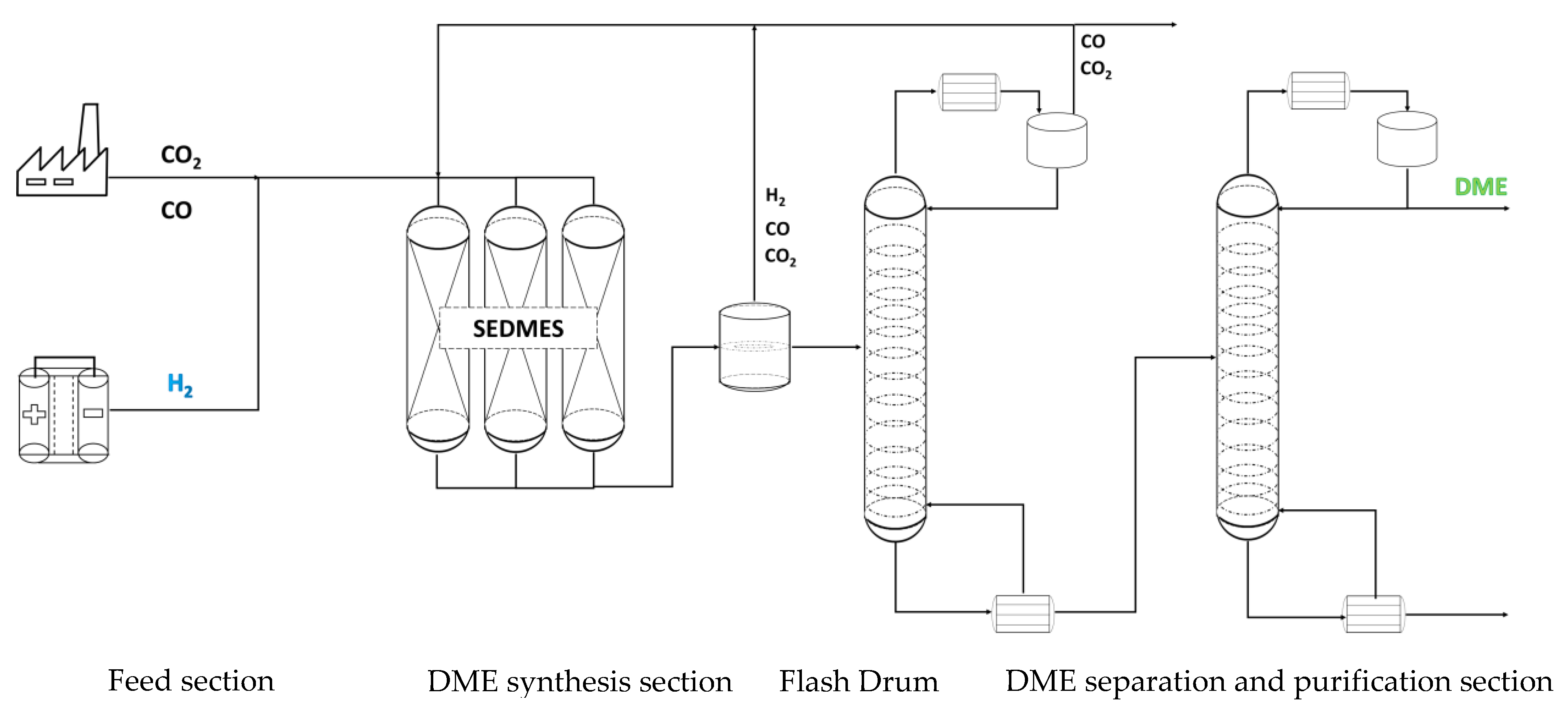
Figure 4.
The adapted SEDMES process flowsheet including the SED column. DME conversion and purification.
Figure 4.
The adapted SEDMES process flowsheet including the SED column. DME conversion and purification.
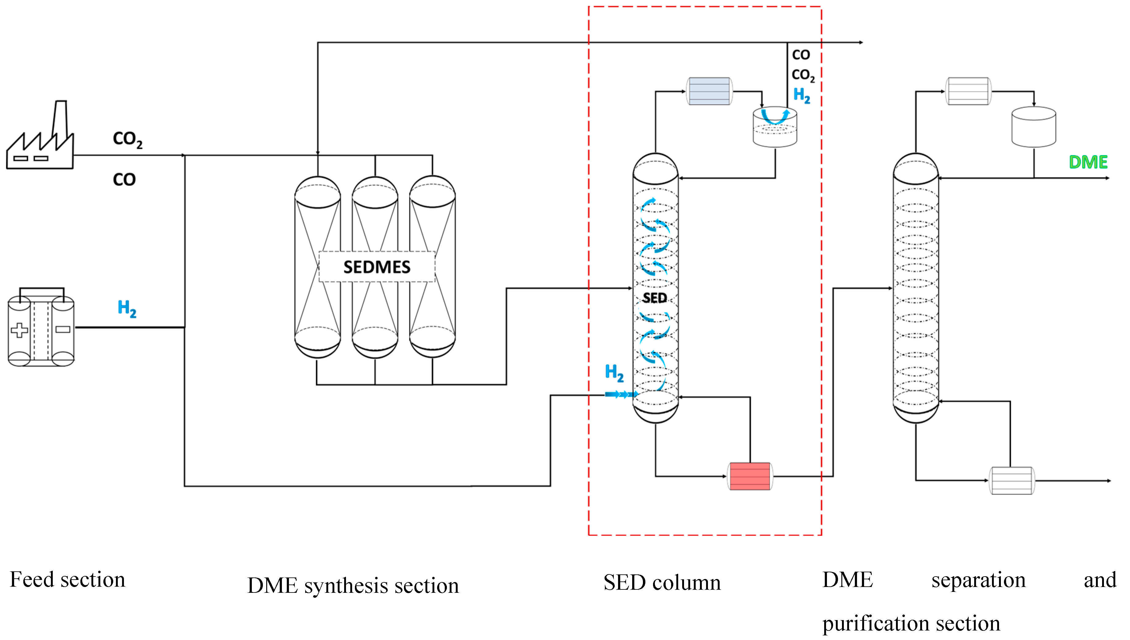
Figure 5.
A simplified process block diagram of the one-step DME production via syngas produced by means of tri-reforming. Reprinted with permission [25].
Figure 5.
A simplified process block diagram of the one-step DME production via syngas produced by means of tri-reforming. Reprinted with permission [25].
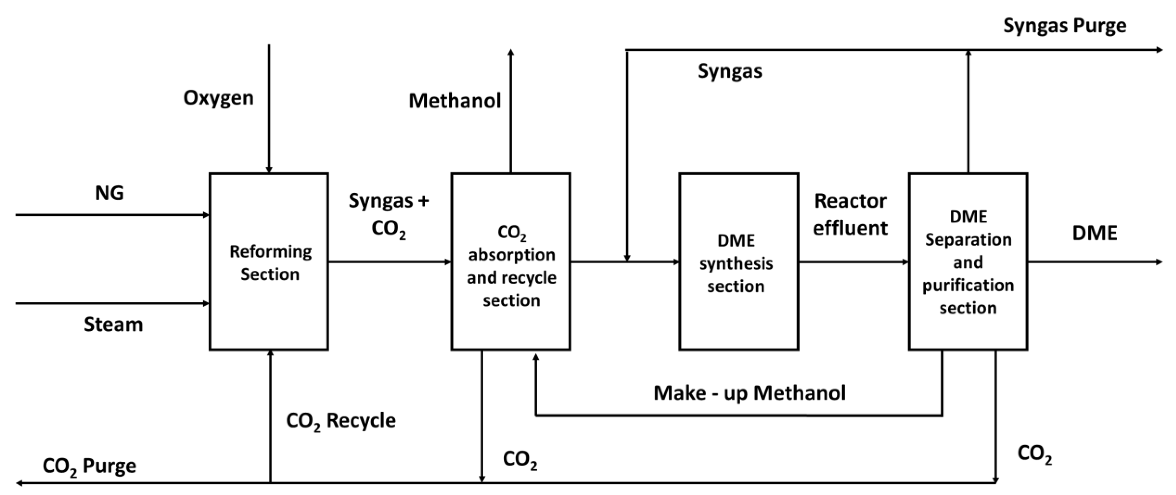
Figure 6.
A proposed process flow diagram for the DIDR process with SED incorporated
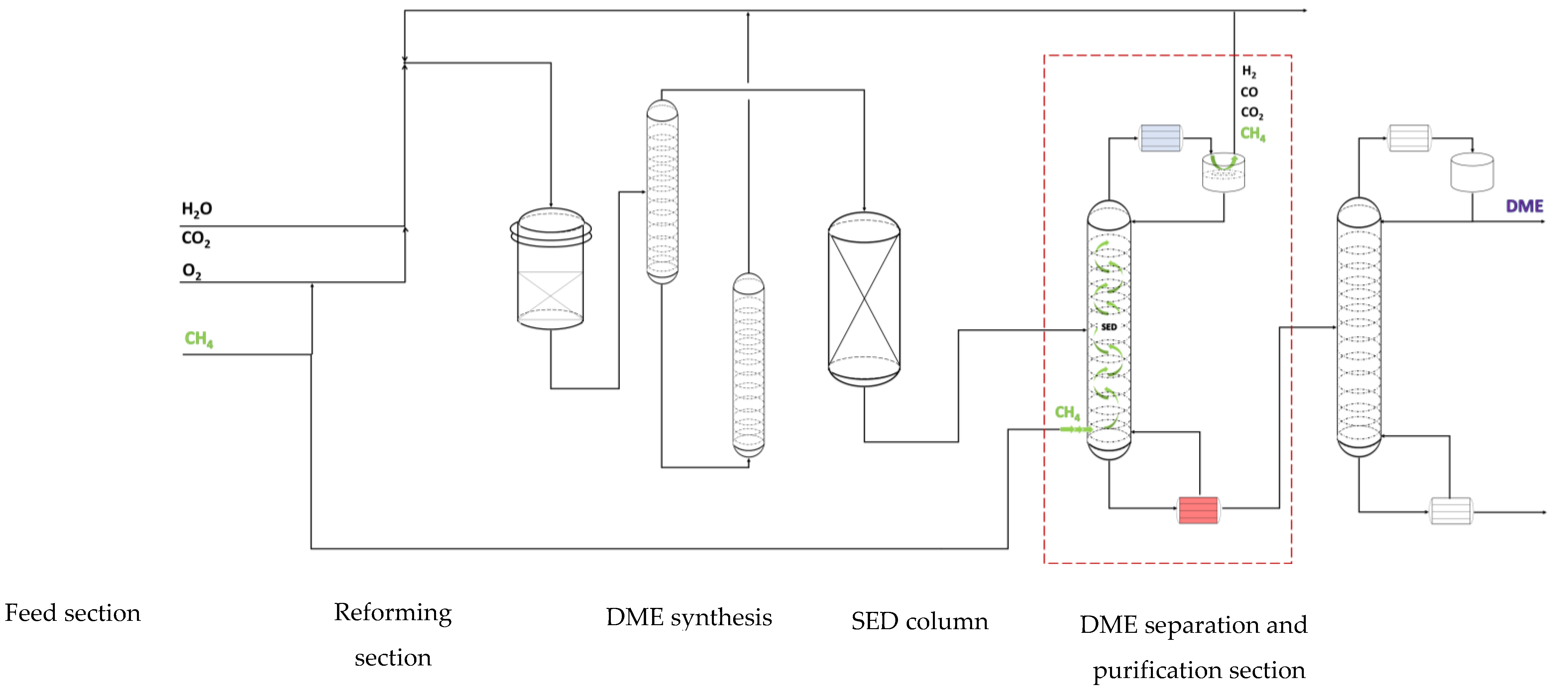
Figure 7.
Comparison of the results for the conventional SEDMES product stream purification (red bars) and SEDMES with SED incorporated in the downstream separation train (blue bars). The comparison parameters are; total energy consumption; DME product losses; number of equilibrium stages and reflux ratio.
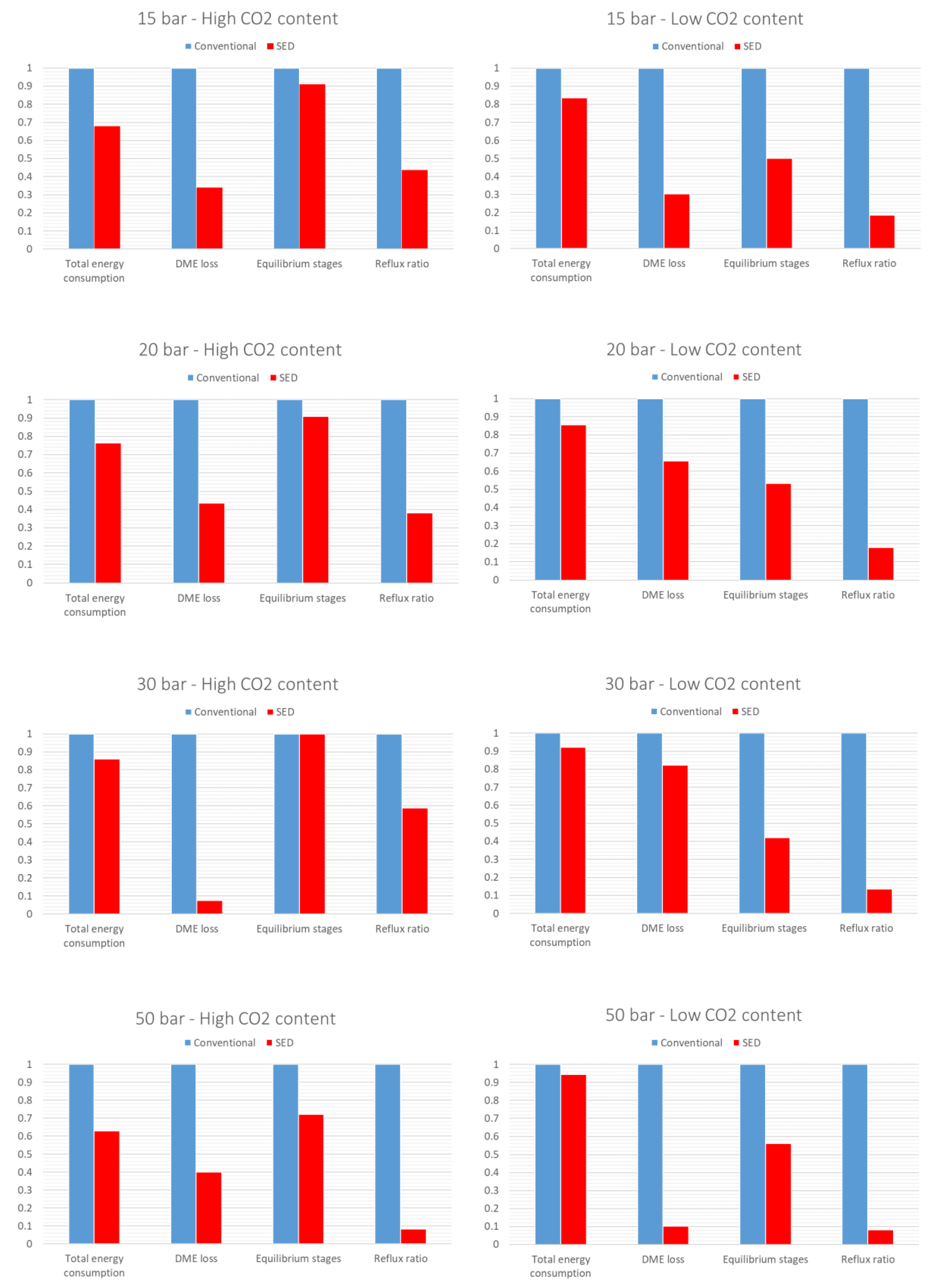
Figure 8.
CH4 / hydrocarbons in the DME product (Top Left), CO2 in the DME product (Top right), DME purity (Bottom left) and Total Energy Consumption (Bottom right). Red surfaces presents design boundaries as per Table 4, red spheres present optimal design points of SED.
Figure 8.
CH4 / hydrocarbons in the DME product (Top Left), CO2 in the DME product (Top right), DME purity (Bottom left) and Total Energy Consumption (Bottom right). Red surfaces presents design boundaries as per Table 4, red spheres present optimal design points of SED.
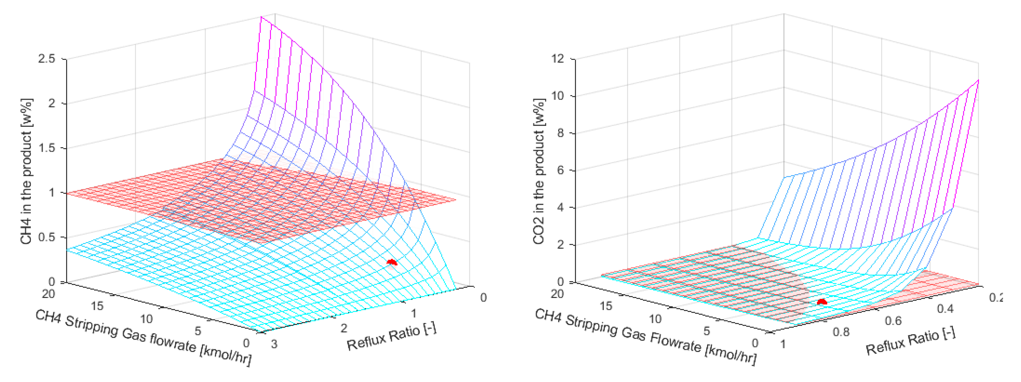
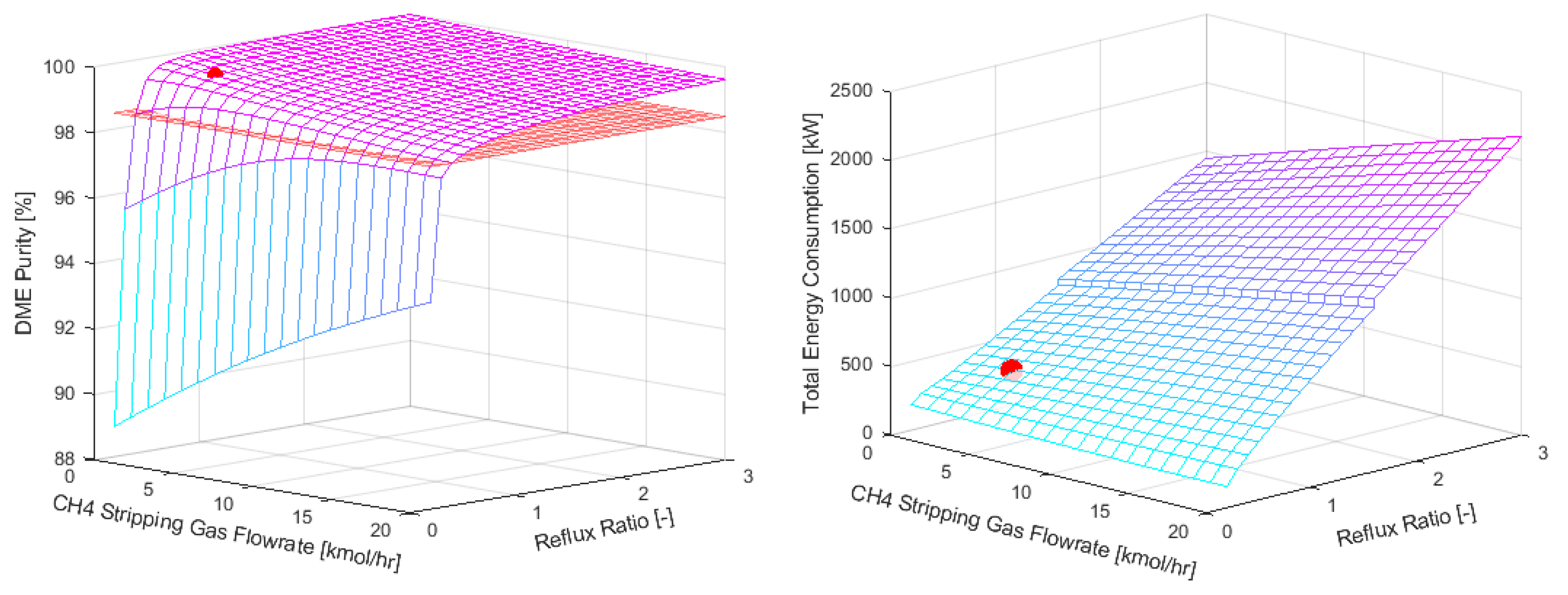
Table 2.
The feed composition to the downstream separation units that originates from the DME reactor.
Table 2.
The feed composition to the downstream separation units that originates from the DME reactor.
| Component | SEDMES | DIDR [24] | |
| Low CO2 concentration [mol%] | High CO2 concentration [mol%] | Composition [mol%] |
|
| DME | 48.84 | 39.29 | 24.43 |
| CO2 | 2.77 | 21.41 | 33.38 |
| CO | 10.25 | 7.21 | 9.61 |
| H2 | 36.99 | 30.15 | 14.48 |
| H2O | 0.21 | 0.16 | 2.11 |
| MeOH | 0.94 | 1.78 | 14.45 |
Table 3.
Numerical values of the parameters presented in the graphs in Figure 7 for the comparison of the conventional SEDMES product stream purification with and without SED incorporated in downstream processing.
Table 3.
Numerical values of the parameters presented in the graphs in Figure 7 for the comparison of the conventional SEDMES product stream purification with and without SED incorporated in downstream processing.
| Cases | 15 bar | |||
| High CO2 content | Low CO2 content | |||
| Conventional | SED | Conventional | SED | |
| Total energy consumption [kW] | 1253 | 850 | 1059 | 886 |
| DME loss [wt%] | 1.36 | 0.46 | 1.43 | 0.43 |
| Equilibrium stages [-] | 11 | 10 | 16 | 8 |
| Reflux ratio [-] | 1.70 | 0.74 | 3.35 | 0.62 |
| Cases | 20 bar | |||
| High CO2 content | Low CO2 content | |||
| Conventional | SED | Conventional | SED | |
| Total energy consumption [kW] | 1164 | 888 | 1065 | 912 |
| DME loss [wt%] | 1.36 | 0.59 | 0.90 | 0.59 |
| Equilibrium stages [-] | 11 | 10 | 15 | 8 |
| Reflux ratio [-] | 1.70 | 0.65 | 2.80 | 0.50 |
| Cases | 30 bar | |||
| High CO2 content | Low CO2 content | |||
| Conventional | SED | Conventional | SED | |
| Total energy consumption [kW] | 1381 | 1187 | 1122 | 1034 |
| DME loss [wt%] | 1.36 | 0.10 | 0.91 | 0.75 |
| Equilibrium stages [-] | 11 | 11 | 19 | 8 |
| Reflux ratio [-] | 1.70 | 1.0 | 3.70 | 0.50 |
| Cases | 50 bar | |||
| High CO2 content | Low CO2 content | |||
| Conventional | SED | Conventional | SED | |
| Total energy consumption [kW] | 1673 | 1054 | 1260 | 1190 |
| DME loss [wt%] | 1.11 | 0.35 | 1.07 | 0.11 |
| Equilibrium stages [-] | 25 | 18 | 25 | 14 |
| Reflux ratio [-] | 6.10 | 0.50 | 6.20 | 0.50 |
Table 4.
Results of the sensitivity analysis on the SED column.
| Parameter | Conventional Distillation | Stripping Enhanced Distillation |
|---|---|---|
| Reflux Ratio | 0.97 | 0.68 |
| CH4 stripping gas flowrate [kmol∙hr-1] | 0 | 3.16 |
| CO2 in the DME product [w%] | 0.1 | 0.1 |
| DME purity [w%] | >99 | >99 |
| DME losses [w%] | <1 | <1 |
| Total Energy Consumption [kWh] | 522 | 427 |
Disclaimer/Publisher’s Note: The statements, opinions and data contained in all publications are solely those of the individual author(s) and contributor(s) and not of MDPI and/or the editor(s). MDPI and/or the editor(s) disclaim responsibility for any injury to people or property resulting from any ideas, methods, instructions or products referred to in the content. |
© 2023 by the authors. Licensee MDPI, Basel, Switzerland. This article is an open access article distributed under the terms and conditions of the Creative Commons Attribution (CC BY) license (http://creativecommons.org/licenses/by/4.0/).
Copyright: This open access article is published under a Creative Commons CC BY 4.0 license, which permit the free download, distribution, and reuse, provided that the author and preprint are cited in any reuse.


