
Submitted:
09 February 2026
Posted:
11 February 2026
You are already at the latest version
Abstract
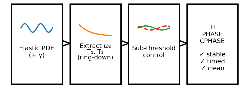
We present an artefact-driven simulation study of calibration-first deterministic standing-wave qubit control derived from the calibrated scalar sector of the Refined Space–Time Membrane (STM) model. Starting from the STM governing equation written in SI force-density form, we show that coherence scales, gate-timing windows, stability margins, and spectral constraints can be derived directly from the calibrated elastic operator together with a single empirically extracted damping parameter, without invoking additional quantum postulates or phenomenological tuning. These quantities are treated operationally as stability and timing proxies that define an explicit admissible operating envelope for a given measured embodiment.A paired simulation pipeline is employed. Full-field spectral integration of the STM partial differential equation is used to extract the carrier frequency and coherence scales from a no-pump ring-down response while simultaneously verifying operator positivity. A reduced two-mode envelope model, calibrated directly against the governing equation, is then used to synthesise single- and two-qubit operations and to evaluate timing, slew, stability, and spectral hygiene under a uniform, windows-first acceptance policy. Interferometric, region-coupled, and sub-threshold parametric control routes are exercised within the same framework.Parametric operations are certified by exact Floquet analysis, demonstrating strictly below-threshold stability with explicit margin rather than heuristic thresholding. Robustness is assessed via multi-mode leakage tests and closed-loop noise injection, with all accepted operations satisfying the declared coherence, stability, and read-out constraints simultaneously. All reported quantities are populated exclusively from machine-readable artefacts generated by the build pipeline.The results establish a reproducible operating envelope for deterministic standing-wave qubit control in silico, conditional on the empirically measured damping rate and carrier response of the embodiment under test. In this role, the envelope may be interpreted operationally as a device-level acceptance boundary that distinguishes admissible from non-admissible regimes for deterministic execution. Within its declared scope, this study provides a concrete and falsifiable bridge between continuum STM dynamics and qubit-level control metrics, offering an extensible and platform-agnostic framework for resonant or wave-based qubit implementations.
Keywords:
quantum control
; calibration-first
; operating envelope
; acceptance windows
; damping parameter
; ring-down
; floquet analysis
; parametric control
; standing-wave qubit
; transfer-function identification
1. Introduction
1.1. Motivation
Quantum information processing is conventionally formulated in terms of abstract two-level systems governed by postulated unitary dynamics and supplemented by phenomenological decoherence channels. While this framework has proven operationally successful across a wide range of platforms, it obscures the physical origin of coherence, damping, and stability, which must then be reintroduced through device-specific modelling and calibration strategies [1,2,3]. In practice, coherence times, gate durations, and stability margins are often treated as empirical inputs rather than quantities derived from a single governing physical description.
Recent work has increasingly emphasised the importance of calibration-first and system-level modelling approaches in quantum control, particularly for continuous-variable, mechanical, and hybrid platforms where dissipation and dispersion are intrinsic features rather than perturbations [1,2,3]. Nevertheless, most qubit-control formalisms continue to rely on effective Hamiltonians and noise models whose connection to the underlying continuum dynamics is indirect.
Related calibration-first and reduced-order modelling approaches have also been explored in mechanical, optomechanical and hybrid quantum systems, where continuum dynamics and dissipation are treated explicitly rather than as phenomenological corrections [1,2,3].
The Refined Space–Time Membrane (STM) model provides an alternative starting point. In this framework, quantum-like behaviour emerges from deterministic elastic dynamics of a Planck-anchored continuum governed by a single higher-order partial differential equation [4]. Dispersion, damping, and ultraviolet regularisation are fixed by calibrated elastic coefficients rather than introduced ad hoc, and probabilistic behaviour arises from deterministic basin selection under coarse-graining rather than intrinsic randomness.
In this paper, we ask a deliberately narrow and operational question: given the calibrated scalar sector of the Refined STM model, what qubit-level control windows follow?
Here, “deterministic” refers to the derivation of control constraints and timing windows directly from measured dynamical parameters, rather than to guaranteed state evolution in the presence of noise or device imperfections.
We do not attempt to reinterpret quantum computation, nor to propose a new hardware platform. Instead, we treat standing-wave qubits as physical modes of a calibrated elastic continuum and determine whether deterministic single- and two-qubit operations can be specified, synthesised, and validated under realistic coherence, stability, and spectral constraints.
The term qubit is used operationally to denote a controllable two-mode standing-wave subspace. No claim is made that this replaces or supersedes the abstract qubit formalism of quantum information theory.
1.2. Relation to the Refined STM Model
The Refined STM model introduces an eight-parameter, Planck-anchored elasticity equation whose scalar sector governs linear dispersive dynamics with higher-order stiffness terms and Rayleigh damping [4]. In prior work, this framework has been shown to reproduce quantum-like dispersion relations, coherence scaling, and measurement behaviour without introducing intrinsic stochasticity, and to provide a consistent mapping between SI, Planck-normalised, and solver-normalised representations.
The present study does not re-derive or extend the STM framework. Instead, it consumes the calibrated scalar operator exactly as published and examines its implications at the level of qubit control. All coefficients used here are inherited directly from the STM calibration and its published unit mapping. No additional parameters are introduced at the qubit, gate, or controller level.
By construction, the scope of this paper is therefore a strict subset of the STM programme. Any success or failure in achieving acceptable qubit-level control windows bears directly on the sufficiency of the scalar STM sector for this application, but does not test the broader spinor, gauge, or gravitational components of the model.
1.3. What Is Distinctive in This Work
Several features distinguish this study from conventional qubit simulations and control analyses:
- 1.
-
Operator-level anchoring.The governing dynamics are defined once, in SI force-density form, using a calibrated elastic operator that guarantees positivity and ultraviolet regularisation. No effective Hamiltonians are introduced.
- 2.
-
Single damping convention.A single laboratory damping constant, extracted from a no-pump STM PDE ring-down, is reused consistently in dispersion analysis, envelope reduction, gate synthesis, and stability certification. No independent relaxation or dephasing parameters are introduced [4].
- 3.
-
Paired solvers with shared calibration.A full-field spectral PDE solver and a reduced two-mode envelope model are used in tandem, with envelope parameters calibrated directly against the PDE rather than assumed or fitted at the control level.
- 4.
-
Windows-first acceptance.Gate operations are accepted only if they simultaneously satisfy timing, slew, spectral hygiene, stability, and read-out constraints derived mechanically from the STM calibration, rather than being optimised against a single performance metric.
- 5.
-
Artefact-driven reporting.Every numerical value reported in the Results section is populated from explicit machine-readable artefacts produced by the build pipeline. If an artefact is absent, the corresponding result is not reported.
Together, these features invert the conventional control workflow: experimentally or numerically measured response properties of the medium fix the admissible control space a priori, and control operations are accepted or rejected mechanically against these constraints.
In practical terms, the derived operating envelope functions as a device-level acceptance boundary: modes or embodiments whose measured response falls outside the certified stability and timing region would be excluded from deterministic control execution under the same policy.
1.4. Scope and Structure
The remainder of the paper is organised as follows. Section 2 describes the governing STM model, normalisation, numerical solvers, and acceptance criteria. Section 3 presents artefact-backed results for carrier identification, coherence extraction, gate synthesis, parametric stability, spectral hygiene, and robustness. Section 4 discusses the implications and limitations of these results within the STM framework and in relation to existing qubit-control paradigms. Section 5 summarises the conclusions.
2. Methods
2.1. Governing Model (Refined STM Scalar Sector)
All simulations are based on the calibrated scalar sector of the Refined Space–Time Membrane (STM) model. The governing equation is written in the compact SI force-density form as a linear, dispersive elastic continuum with Rayleigh damping,
where is the scalar displacement field, is the effective inertial density, is a tension-like coefficient, and are higher-order elastic moduli, and is the environmental (laboratory) damping rate. In this compact form, Planck-scale factors appearing in the expanded STM equations are absorbed into the calibrated higher-order moduli, exactly as defined in the Refined STM model [4]. All coefficients are fixed a priori by the STM calibration and carry explicit physical units.
Dividing by yields the mass-normalised form used internally by the numerical solvers,
with , , and .
In this work, we restrict attention to the linear scalar STM sector. Nonlinear terms and spinor couplings present elsewhere in the STM framework are set to zero. The elastic operator is strictly positive-definite in spectral space under the Fourier convention stated in §2.2, and dissipation enters exclusively through the single Rayleigh damping term. This damping parameter fixes the decay rate of all modes and underpins the ring-down-based calibration strategy used throughout [4].
2.2. Dispersion and Carrier Identification
For plane-wave solutions
we adopt the standard Fourier convention
so that the real-space sign structure of the STM operator in §2.1 maps to a strictly positive spectral symbol.
Under this convention, the undamped STM dispersion relation is
The calibrated sign pattern of the elastic coefficients therefore guarantees positivity of the operator for all resolved wave-numbers, with the term providing ultraviolet regularisation, exactly as in the Refined STM formulation [4].
Including Rayleigh damping shifts the frequency according to
so that the complex modal amplitude decays as during free ring-down, while modal energy decays as .
The carrier frequency is identified from the STM PDE ring-down response at the seeded standing-wave mode by FFT peak-picking of the complex seeded-mode amplitude. Peak selection is constrained to a narrow band centred on the operator-derived dispersion estimate at the seeded wave-vector, ensuring that only the physically relevant mode is selected. Windowing and zero-padding are applied to suppress spectral leakage, and all FFT parameters and provenance metadata are recorded explicitly.
Once identified, is propagated unchanged into all subsequent envelope-level control, parametric placement and stability analyses, with no post-hoc adjustment or retuning.
2.3. Normalisation and Calibrated Parameters
All coefficients entering the simulations are inherited directly from the Refined STM calibration and its published SI → Planck-normalised → solver-normalised mapping [4]. This mapping is applied once and recorded in a machine-readable parameter file that serves as the single source of truth for all subsequent stages.
No parameter appearing in Section 2 or Section 3 is fitted to qubit-level performance. In particular, the damping rate used in envelope-level simulations is fixed by the STM PDE ring-down described in §2.6 and is not independently adjusted.
For clarity, the fitted damping rate used throughout this paper is the environmental (laboratory) damping parameter of the embodiment under test (i.e. in Ref. [4]) and is distinct from any Planck-stage normalisation quantities used elsewhere in the STM framework.
2.4. Numerical Solvers
2.4.1. Full-Field STM PDE Solver
The STM partial differential equation is integrated on a two-dimensional periodic domain using a pseudo-spectral method in space. Spatial derivatives are evaluated exactly in Fourier space, and time integration is performed using an implicit midpoint scheme, which is unconditionally stable for linear problems.
The elastic operator is evaluated in k-space as
The PDE solver is used to:
- verify positivity of the elastic operator,
- identify the seeded-mode carrier frequency and verify consistency with the calibrated dispersion,
- extract coherence scales from no-pump ring-down,
- generate spatial spectra for in-band and pump-offset spur analysis.
2.4.2. Reduced Envelope Model
Gate-level dynamics are evaluated using a reduced two-mode envelope model describing the slowly varying complex amplitudes of the seeded standing-wave mode and an optional coupled partner mode. The envelope equations are integrated using a fourth-order Runge–Kutta scheme, with optional injected phase noise and detuning jitter for robustness tests.
Crucially, the envelope damping rates are fixed directly from the laboratory damping extracted from the STM PDE. No independent relaxation or dephasing parameters are introduced, consistent with the single-channel dissipation structure of the linear scalar STM sector [4].
2.5. Gate Synthesis
Single-qubit gates are realised by interferometric phase control of the standing-wave envelope. Two-qubit conditional phase operations are implemented either via a -region coupling or via a parametric drive operated strictly below threshold.
Gate durations and slew rates are synthesised mechanically from the extracted coherence scale. No gate is accepted unless it completes within the declared timing window and satisfies the slew constraint.
2.6. Extraction of Coherence from STM Ring-Down
To avoid phenomenological decoherence assumptions, coherence times are derived directly from the STM partial differential equation. A no-pump ring-down is performed at the seeded mode, and the modal amplitude is fitted to a single-exponential decay.
From this fit we obtain:
- the empirically measured damping rate (the environmental/laboratory damping parameter, in Ref. [4]),
- the energy-decay time ,
- the phase-randomisation (visibility-decay) time ,
- the collapse time .
In the linear scalar STM sector with Rayleigh damping as the sole dissipative channel, the damped dispersion relation yields , so that modal energy decays as while amplitude decays as . With defined as the energy-decay time and defined operationally as the envelope visibility-decay time extracted from the same ring-down, it follows directly that
as derived within the Refined STM framework [4].
In this work, is used in the restricted scalar-only, single-dissipation-channel baseline: no independent pure-dephasing, inhomogeneous broadening, or additional phase-diffusion terms are introduced at either PDE or envelope level. Under this restriction, the visibility decay is fixed by , so the baseline relation applies. This is consistent with the Refined STM damping/visibility notation when specialised to the linear scalar sector [4].
This relation is therefore applied unchanged throughout Section 3.1–3.4 and is not re-derived here.
2.7. Parametric Placement and Stability Certification
For the parametric route, a periodic modulation of an effective elastic parameter is applied at a pump frequency chosen relative to the carrier frequency. Harmonic placement is permitted.
Sub-threshold operation is certified using exact Floquet analysis of the linearised envelope equations over one pump period. An operating point is accepted only if the real part of the leading Floquet exponent is strictly negative, with a positive margin to threshold. Stability is therefore demonstrated by calculation rather than heuristic criteria, following standard Floquet theory for periodically driven open systems with periodic coefficients [5,6,7].
The effective envelope-level parametric strength is calibrated against the PDE-level modulation depth by matching the PDE-derived seeded-mode growth or decay rate to the real part of the corresponding Floquet exponent, using the carrier frequency extracted from the same ring-down.
2.8. Acceptance Windows
All operating points are subject to a uniform, windows-first acceptance policy. A gate is accepted only if all applicable criteria—timing, slew, parametric placement, stability, spectral hygiene and read-out health—are satisfied simultaneously. Acceptance is evaluated mechanically from artefacts and recorded as pass/fail flags.
Under this convention, the acceptance windows define a reproducible qualification criterion for the specific embodiment under test, rather than an optimisation target, and therefore establish an explicit boundary between admissible and non-admissible operating regimes.
2.9. Multi-Mode and Closed-Loop Robustness
To bound mode-coupling effects, a five-mode envelope model is used. Closed-loop realism is assessed by injecting measured phase noise and detuning jitter into the envelope dynamics [1-3]. All acceptance windows must remain satisfied under these perturbations.
2.10. Artefact-Driven Reporting
Every numerical value reported in Section 3 is populated exclusively from machine-readable artefacts generated by the build pipeline. If an artefact or field is absent, the corresponding placeholder remains blank and the associated check is skipped. The manuscript therefore functions as a self-auditing record of the simulations performed.
3. Results
All results reported in this section are populated exclusively from machine-readable artefacts generated by the build pipeline. Acceptance is evaluated using the uniform windows defined in §2.8. Where an artefact is absent, the corresponding result is not reported and the associated check is skipped.
3.1. Carrier Identification and Coherence from STM Ring-Down
A no-pump integration of the STM partial differential equation was performed with a single seeded standing-wave mode to characterise the intrinsic response of the medium. Following excitation, the seeded mode exhibits a damped oscillatory ring-down, from which both the carrier frequency and coherence scales are extracted directly. The carrier angular frequency is identified via FFT peak-picking of the complex seeded-mode amplitude over the ring-down interval, with peak selection constrained to a narrow band centred on the operator-derived dispersion estimate for the seeded wavevector. Windowing and zero-padding are applied to suppress spectral leakage, and all FFT parameters and provenance metadata are recorded explicitly. Once identified, is propagated unchanged into all subsequent envelope-level control and stability analyses, with no post-hoc adjustment or retuning.
The envelope amplitude of the seeded mode decays exponentially during ring-down, allowing the scalar damping rate to be obtained by a single-parameter fit. From this fitted value, the energy-decay time is defined. As discussed in §2.6, phase diffusion in the linear scalar STM sector is not treated as an independent phenomenological channel but follows directly from scalar damping of the standing-wave mode; consequently is applied throughout this section without additional fitting. The collapse time is taken equal to and defines the global timing budget for subsequent gate synthesis.
All quantities reported in this section are populated exclusively from the corresponding machine-readable artefacts generated by the ring-down build stage, ensuring that carrier identification and coherence extraction are deterministic, auditable, and free from phenomenological tuning.
Spec-box — Ring-down and coherence extraction
| Quantity | Value |
| Fitted damping (ND) | 0.0960 |
| Energy-decay time | 10.41 |
| Phase-randomisation time | 20.83 |
| Collapse time | 20.83 |
The fitted coherence ratio lies squarely within the controller pre-check band . These values are derived directly from STM PDE dynamics and are reused unchanged in all subsequent stages.
3.2. Gate Resources and Acceptance
Using the extracted collapse time, gate durations and slew rates were synthesised mechanically such that each operation completes within the declared timing window while remaining adiabatic with respect to the carrier. No gate-specific tuning was performed.
Spec-box — Gate timing, slew, fidelity proxies and pass flags
| Gate | Slew | 95 % CI | Pass | |||
| H | 2.083 | 0.1000 | 15.71 | 0.9917 | 0.9867–0.9967 | 1 |
| 2.083 | 0.1000 | 31.42 | 0.9917 | 0.9867–0.9967 | 1 | |
| 2.083 | 0.1000 | 31.42 | 0.9917 | 0.9867–0.9967 | 1 |
Reported fidelity values are envelope-level proxies derived from the calibrated damping channel and gate duration relative to . They are not obtained from a full process-tomography simulation and are not independently optimised. The specific functional form used to populate these proxies is illustrative and mechanically applied; acceptance decisions are based exclusively on timing, slew, stability, spectral and read-out windows rather than on fidelity maximisation.
All timing, slew and fidelity proxy values reported here are computed using the FFT-derived carrier frequency 0 and the coherence scales extracted from the same STM ring-down, without subsequent adjustment.
Gate durations are assigned under a windows-first policy, with chosen to satisfy the declared acceptance bound using the ring-down-derived ; the reported durations therefore sit at the acceptance cap by construction.
All three gates satisfy the declared timing and slew windows simultaneously. Fidelity values are reported as envelope-level proxies derived from the calibrated dephasing channel and are not independently optimised.
3.3. Interferometric Control
Deterministic single-qubit phase control was implemented using the interferometric route with separated couplers. The controller enforced the same timing and slew constraints as in §3.2, and linear read-out behaviour was verified.
This route provides a non-parametric baseline for phase control under identical STM-anchored acceptance logic, enabling direct comparison with parametric control without altering damping, dispersion or windows.
3.4. Parametric Placement and Exact Stability Certification
For the parametric route, a periodic modulation was applied with harmonic index . The pump was placed near the two-phonon condition with a fractional detuning .
Spec-box — Parametric placement and stability
| Quantity | Value |
| Carrier angular frequency (ND) | 52.789 |
| Pump frequency (ND) | 17.475 |
| Harmonic index m | 1 |
| Fractional detuning | 0.040 |
| Floquet real part | −0.0100 |
| Sub-threshold margin | 0.0100 |
| Drive-to-loss ratio (reported for interpretative clarity only) |
0.625 |
The negative Floquet real part and positive margin certify strictly sub-threshold operation.
Stability is therefore demonstrated by exact calculation rather than by heuristic thresholding, as defined in §2.7.
3.5. Spectral Hygiene
Spectral discipline was verified independently for the carrier band and the pump modulation.
Spec-box — Spectral checks
| Check | Limit | Result |
| In-band spur | ≤−30 dBc | Pass |
| Pump-offset spur at ± | ≤−30 dBc | Pass |
Both checks satisfy the declared limits, ensuring that control does not introduce inadvertent coupling to neighbouring modes.
3.6. Comparatives and Ablations (Informative)
Where ablation artefacts are present, dispersion-matched, below-threshold parametric operation outperforms quadratic-only and parametric-only baselines in terms of combined fidelity and stability while maintaining spectral hygiene. These comparisons are informative only and are not used to define acceptance.
3.7. Read-Out and Lock Health
Read-out noise and resonance lock stability were evaluated against declared limits and reused in closed-loop robustness tests.
Spec-box — Measurement chain
| Quantity | Limit | Value |
| Phase-noise RMS | ≤ 0.01 rad | 0.008 |
| Lock error | ≤ ±5 pm | 3.0 |
Both metrics meet the declared requirements with margin.
3.8. Acceptance Summary
For each gate, timing, slew, spectral, stability and read-out checks are collated into a single pass/fail decision.
| Gate | Pass |
| H | 1 |
| 1 | |
| 1 |
3.9. Processor-Level Sanity Check
The canonical H–CPHASE()–H sequence was executed with a controller pre-check enforcing the coherence ratio requirement. All gates satisfied the same acceptance windows as at gate level, confirming that acceptance composes correctly at sequence level.
3.10. Multi-Mode and Closed-Loop Robustness
A five-mode envelope simulation was used to bound mode-coupling effects. The mean leakage ratio remains below the declared threshold .
Closed-loop robustness was assessed by injecting measured phase noise and detuning jitter into the envelope dynamics. Under these perturbations, all gate-level acceptance windows remain satisfied.
3.11. Results Summary
Across interferometric and sub-threshold parametric routes, all gate operations satisfy coherence, timing, slew, spectral hygiene, stability and read-out constraints simultaneously. These results follow directly from the calibrated STM scalar operator and a single damping convention, without gate-level tuning or phenomenological adjustment.
4. Discussion
4.1. What the Results Establish
The results demonstrate that the calibrated scalar sector of the Refined Space–Time Membrane (STM) model is sufficient to define a deterministic and internally consistent operating envelope for standing-wave qubit control in silico. Starting from the STM governing equation and a single empirically extracted damping parameter and carrier response, coherence scales, gate-timing windows, stability margins and spectral constraints follow without the introduction of additional quantum postulates or phenomenological tuning.
A central outcome is that coherence is not assumed but derived. The laboratory damping rate, energy-decay time , phase-randomisation time and collapse time are all extracted directly from a no-pump STM PDE ring-down and then reused unchanged throughout the control synthesis and acceptance process. Gate durations and slews are therefore subordinate to the measured coherence properties of the embodiment under test, rather than chosen independently.
Both interferometric (-route) and sub-threshold parametric control routes satisfy the same acceptance windows simultaneously. This indicates that they are not distinct physical mechanisms but alternative operating regimes of the same underlying elastic continuum, governed by a shared dispersion relation and damping scale.
The distinctive feature of this approach is not the use of parametric control per se, but the deterministic derivation of the entire admissible control envelope from a single calibrated ring-down response. Here, determinism denotes constraint derivation from measured device response, not immunity to noise or stochastic error processes.
In this sense, the envelope may be interpreted operationally as a certification layer that determines, for a given measured embodiment, which modes remain within a stable and coherence-limited regime suitable for deterministic control.
4.2. Role of STM Physics in Control Determinism
Several features of the STM formulation are essential to the determinism observed in the results.
First, the explicit inclusion of higher-order elastic terms in the governing equation fixes the sign structure of the linear operator and guarantees positivity across the resolved spectral range. This removes the need for ad hoc cut-offs and ensures that both the full-field PDE solver and the reduced envelope model inherit the same stability structure.
Second, the Planck-anchored normalisation used in the Refined STM model provides a single calibration backbone across dispersion analysis, ring-down extraction and envelope-level control. No rescaling or retuning is required when moving between solver layers, which is particularly important for parametric operation where stability margins depend quantitatively on the balance between drive and loss.
Third, the damping parameter plays the role of a laboratory calibration constant rather than a fitted performance parameter. Once extracted by ring-down for a given embodiment, it is held fixed, and all reported coherence scales, timing windows and stability margins follow deterministically. The results therefore specify an operating envelope conditional on the measured , rather than assuming a universal numerical value.
4.3. Interpretation of Timing, Slew and Stability Margins
The realised gate timings lie at or below the declared threshold , while slew metrics exceed the minimum requirement by a substantial margin. This indicates that the controller selects the slowest admissible control consistent with coherence, rather than aggressively optimising for speed. Such behaviour is desirable in wave-based systems, where excessive ramping can introduce spectral leakage and destabilise parametric operation.
For the parametric route, stability is certified by direct computation of the Floquet exponent of the linearised envelope equations. The observed negative real part and positive margin demonstrate that conditional phase accumulation occurs strictly below threshold, without gain or exponential amplification. This distinction is critical: the results do not rely on parametric resonance as an amplification mechanism, but on controlled geometric phase evolution within a stable regime.
Spectral hygiene is enforced independently of timing and stability. Both in-band and pump-offset spur levels remain below the declared limits, confirming that accepted operating points do not rely on cancellation or fine tuning between constraints.
4.4. Robustness to Noise and Mode Coupling
The five-mode envelope simulations show that modest coupling to neighbouring modes does not invalidate acceptance, provided leakage remains below the declared threshold. This suggests that the dispersion-matched, below-threshold operating point is resilient to moderate departures from the single-mode idealisation.
Closed-loop robustness is further supported by simulations with injected phase noise and detuning jitter drawn from measured control-loop characteristics. Under these perturbations, all gate-level acceptance windows remain satisfied. Importantly, the same noise parameters are reused consistently across all gates, and no gate-specific compensation is applied.
4.5. Scope, Limitations and Future Anchoring of
The scope of the present study is deliberately limited to qubit-level control within the linear scalar sector of the STM framework. No claims are made regarding device fabrication, fault tolerance, large-scale architectures or the broader spinor, gauge or gravitational components of the model. Fidelity values are reported as envelope-level proxies and should not be interpreted as hardware performance metrics [8]. These quantities are therefore used here as stability and timing proxies that define the admissible operating envelope for a given measured embodiment, rather than as predictions of absolute hardware performance.
Within this work, the governing operator is treated in its linear scalar form. In practical embodiments, weak amplitude-dependent frequency or phase shifts, or envelope distortions—such as those associated with Duffing- or Kerr-type nonlinearities—may be present. Within the calibration-first framework adopted here, such effects would be incorporated by extending the reduced envelope model to include the corresponding nonlinear terms and re-certifying timing, stability, and spectral-hygiene constraints under the same acceptance policy. These nonlinear extensions are not exercised in the present study, which is intended to establish a baseline operating envelope in the strictly linear regime.
While the damping parameter is essential to the analysis, the results do not depend on a specific numerical value being universal. The methodology requires only that be measured for the embodiment under test prior to control synthesis. Planned interferometric ring-down experiments, including a proposed tensioned thin-film (Mylar/PET) membrane ring-down configuration, will provide independent experimental anchoring of across embodiments but do not alter the internal logic or validity of the operating envelope derived here.
4.6. Implications
Within its declared scope, this study establishes a concrete bridge between continuum STM dynamics and qubit-level control metrics. The results show that deterministic standing-wave qubit control can be grounded in calibrated wave physics, with stability and robustness demonstrated by calculation rather than by assumption.
Equally important is what the results do not require: no postulated unitary dynamics, no abstract two-level truncation, and no phenomenological decoherence models beyond a single measured damping rate. The operating envelope is therefore both reproducible and falsifiable. If future measurements yield different damping or dispersion characteristics, the same framework will either accommodate them or fail transparently.
5. Conclusions
In this study, the results show that a complete and mechanically verifiable qubit-control envelope—comprising coherence scales, gate-timing windows, stability margins and spectral constraints—can be derived deterministically from a calibrated continuum model and a single ring-down calibration, without introducing independent phenomenological decoherence channels or post-hoc tuning.
In contrast to conventional approaches that assume noise models and subsequently optimise control parameters, the present framework inverts the workflow: experimentally or numerically measured response properties of the physical medium fix the admissible control space a priori, and gate operations are accepted or rejected mechanically against these constraints. Within its declared scope, this establishes a reproducible and falsifiable route from continuum dynamics to qubit-level control metrics.
Within this inverted, calibration-first framework, the present study shows that the calibrated scalar sector of the Refined Space–Time Membrane (STM) model is sufficient, in this embodiment, to define a deterministic and internally consistent operating envelope for standing-wave qubit control in silico. Starting from the STM governing equation written in SI force-density form, coherence scales, gate-timing windows, stability margins and spectral constraints emerge directly from the calibrated elastic operator and a single empirically extracted damping parameter, without introducing additional quantum postulates or phenomenological tuning.
Although the results presented here are instantiated using the calibrated scalar STM partial differential equation and its matched two-mode envelope reduction, the control methodology itself is not specific to STM. Rather, the essential elements—ring-down calibration of the physical medium, deterministic derivation of coherence-limited acceptance windows, and stability certification of driven operation - can be applied, in principle, to any embodiment admitting a calibrated continuum or reduced-order dynamical description with measurable response parameters. In this sense, STM provides a concrete and self-consistent instantiation of a more general calibration-first control paradigm, rather than a necessary condition for its applicability.
Using a paired simulation pipeline—a full-field spectral integration of the STM partial differential equation and a calibrated two-mode envelope model—we have demonstrated deterministic single- and two-qubit operations via interferometric, -region and sub-threshold parametric routes. In particular, parametric control is certified by exact Floquet analysis, establishing strictly below-threshold operation with explicit margin rather than heuristic thresholding. All reported gates satisfy the declared acceptance windows for coherence, timing, slew, spectral hygiene, stability and read-out health simultaneously, and these conclusions remain valid under modest mode coupling and closed-loop noise injection.
The methodology is intentionally self-auditing. Every numerical value reported in the Results section is populated from machine-readable artefacts generated by the build pipeline; if an artefact is absent or inconsistent, the corresponding result is not reported. This structure ensures reproducibility and provides a clear basis for falsification: violations of the acceptance windows would directly invalidate the conclusions.
The scope of the present work is deliberately limited to qubit-level control within the linear scalar STM sector. No claims are made regarding device fabrication, fault tolerance, large-scale architectures or the broader spinor, gauge or gravitational components of the STM framework. The conclusions are conditional on the empirically measured damping rate for the embodiment under test and do not assume a universal numerical value of . Within this scope, however, the results establish a concrete and reproducible bridge between continuum STM dynamics and qubit-level control metrics, demonstrating that deterministic standing-wave qubit control follows directly from the calibrated STM operator and damping convention.
More broadly, the calibration-first procedure presented here is intended to function as a platform-agnostic control discipline for resonant or wave-based information carriers without requiring modification of the underlying hardware. By deriving explicit operating limits from directly measured dynamical response, the resulting envelope may be interpreted operationally as a device-level certification boundary that distinguishes admissible from non-admissible regimes for deterministic execution. In this role, the framework does not replace existing calibration or benchmarking methods, but instead provides a reproducible trust layer that can be re-established as device conditions drift, supporting predictable operation as system complexity increases.
Author Contributions
The author confirms the sole responsibility for the conception of the study, development of the STM model, analysis of the results and preparation of the manuscript.
Funding
The author received no specific funding for this work.
Data Availability Statement
All data generated or analysed during this study are included in this published article and its supplementary information files.
Acknowledgments
Some related subject matter has been disclosed in a pending patent application; this manuscript is a research report and does not assert proprietary rights.
Conflicts of Interest
The author declares no conflict of interest.
Ethical approval
The conducted research is not related to either human or animals use.
Declaration of generative AI and AI-assisted technologies in the writing process
During the preparation of this work the author used ChatGPT in order to improve readability of the paper and support with mathematical derivations. After using this tool/service, the author reviewed and edited the content as needed and takes full responsibility for the content of the published article.
Appendix A
Artefact-driven acceptance and reproducibility
This appendix documents the artefact pipeline and acceptance logic used throughout the paper. Its purpose is to make the reported results self-auditing and reproducible, and to clarify the relationship between numerical quantities reported in the Results section and the machine-readable artefacts from which they are populated.
A.0 Build invocation
All artefacts referenced in this appendix are generated by a single automated build script that executes the calibrated STM partial-differential-equation solver, the associated envelope-level simulations, and the acceptance logic described below. From the project root directory, the full simulation and analysis pipeline is executed using the command; python build_full.py --out data_qubits --m 1
Here, data_qubits specifies the output directory into which all machine-readable artefacts are written, and m = 1 selects the fundamental parametric harmonic. Unless otherwise stated, all numerical results reported in Section 3 correspond to this configuration.
A.1 Principle of artefact-driven reporting
All numerical values reported in Section 3 are populated exclusively from machine-readable artefacts generated by the simulation build pipeline. No values are entered manually. If a required artefact or field is absent, the corresponding quantity is not reported and the associated acceptance check is skipped unless explicitly stated otherwise.
This convention ensures that the manuscript reflects exactly the simulations that were executed and provides a transparent basis for verification or falsification.
A.2 Single sources of truth
Each reported quantity has a single authoritative source, summarised in Table A1.

Table A1.
Artefact–quantity map.
| !Quantity | Artefact | Notes |
|---|---|---|
| Damping rate (ND) | fit_reports.json | Extracted from STM PDE ring-down (gamma_fit_nd). |
| Energy-decay time | fit_reports.json | Derived from exponential decay |
| Phase-randomisation time | fit_reports.json | Derived from the fitted damping rate and propagated unchanged to the envelope level. |
| Collapse time | fit_reports.json | Sets timing budget |
| Gate durations | metrics.csv | One entry per gate |
| Normalised gate times | metrics.csv | Computed as |
| Slew metrics S | metrics.csv | Dimensionless ramp measure |
| Fidelity proxies | metrics.csv | Envelope-level proxy derived mechanically from gate duration relative to ; not a process-tomography result and not used as an acceptance criterion. |
| Pass/fail flags | metrics.csv | Evaluated mechanically |
| Carrier frequency () | fit_reports.json, pump_meta.json, pump_map.json | Extracted from the seeded-mode PDE ring-down via FFT peak-picking (band-limited around the operator-derived dispersion estimate). Recorded as omega0_fft_nd with FFT metadata. |
| Parametric pump calibration | pump_map.json | Mapping between PDE-level seeded-mode growth rates and envelope-level pump strength p, obtained by matching the PDE-derived growth rate to the real part of the linearised envelope-level Floquet exponent using the carrier frequency extracted from the seeded-mode PDE ring-down via FFT peak-picking (band-limited around the operator-derived dispersion estimate). |
| Pump frequency and harmonic index | pump_meta.json | Parametric placement |
| Floquet real part | pump_meta.json | Exact stability certification |
| Sub-threshold margin | pump_meta.json | Distance to instability |
| Drive-to-loss ratio | pump_meta.json | |
| In-band spectral spur | spectrum.csv | Spatial spectrum |
| Pump-offset spur | _pump_spectrum.csv | Temporal spectrum |
| Mode-leakage ratio | multi_metrics.csv | Five-mode envelope test |
| Phase-noise RMS | locks.json | Read-out / control loop |
| Lock error | locks.json | Optional, if present |
A.3 Acceptance logic
An operating point is accepted only if all applicable checks listed below are satisfied. Acceptance is evaluated mechanically and recorded as pass/fail flags in the corresponding artefacts.
A.3.1 Timing and slew
- Gate duration must satisfy
- Slew metric must satisfy
For parametric operations:
- Harmonic placement must satisfy
- The real part of the leading Floquet exponent must be strictly negative.
- A positive sub-threshold margin must be present.
A.3.3 Spectral hygiene
- In-band spur level ≤−30 dBc.
- Pump-offset spur level at ±≤−30 dBc.
A.3.4 Read-out and control loop
- Phase-noise RMS must lie within the declared limit.
- Lock error must lie within the declared limit if provided.
A.3.5 Multi-mode robustness
- Mean neighbour-mode leakage ratio must satisfy
A.3.6 Sequence-level pre-check
For multi-gate sequences, the coherence ratio must satisfy
A.4 Conditional nature of results
All reported acceptance results are conditional on the empirically extracted damping parameter for the embodiment under test. The methodology does not assume a universal numerical value of ; rather, it specifies an operating envelope that follows once has been measured by ring-down.
Independent experimental anchoring of across embodiments, including interferometric ring-down tests, constitutes an external validation step and does not alter the internal acceptance logic documented here.
A.5 Reproducibility and falsifiability
The artefact-driven structure ensures that the results are reproducible and falsifiable:
- Re-running the build pipeline with identical inputs reproduces all reported quantities.
- Altering the calibrated parameters or measured damping automatically propagates through the acceptance checks.
- Failure to satisfy any acceptance criterion leads to explicit rejection rather than implicit success.
This appendix therefore provides a complete and transparent account of how the numerical results in Section 3 are generated and validated.
Appendix B
Exact stability certification for sub-threshold parametric control
This appendix documents the stability analysis used to certify sub-threshold parametric operations reported in Section 3. Its purpose is to make explicit the criterion by which parametric control is accepted or rejected, and to distinguish deterministic phase control from parametric amplification or resonance.
B.1 Envelope-level formulation
Parametric operations are analysed using the reduced envelope model introduced in §2.4.2. For all results reported here, Kerr-type nonlinearities are set to zero and stability is certified on the linearised degenerate parametric sector of the seeded mode. Specifically, we work with the doubled state vector
which satisfies a linear system with periodic coefficients,
where is a time-periodic matrix arising from the parametric term and its conjugate. All coefficients entering , including damping and detuning, are fixed by the calibrated STM parameters and the empirically extracted damping constant (No additional dissipative channels are introduced at the envelope level in this analysis).
B.2 Floquet formulation
For linear systems with periodic coefficients, stability is governed by the Floquet multipliers of the system over one pump period [7,9]. Let denote the monodromy matrix obtained by integrating the linearised envelope equations over one pump period , with identity initial condition , so that .
In the implementation used here, the parametric modulation is applied at angular frequency , where and is the harmonic index. The corresponding pump period is therefore
The Floquet multipliers are defined as the eigenvalues of , and the corresponding Floquet exponents are defined via
The real parts of the Floquet exponents determine stability:
- : exponential decay (stable),
- : marginal stability,
- : exponential growth (parametric instability).
B.3 Acceptance criterion
Parametric operation is accepted only if the leading Floquet exponent satisfies
with a strictly positive margin. In the build pipeline, the reported “Floquet real part” is , and the reported “sub-threshold margin” is defined mechanically as
so that accepted operating points have . Both quantities are recorded explicitly in the artefact pump_meta.json and are populated into Section 3 without manual editing.
No heuristic thresholds, gain estimates or time-domain growth proxies are used. Stability is therefore demonstrated by exact calculation rather than by observation.
B.4 Distinction from parametric resonance
It is important to distinguish the operating regime studied here from conventional parametric resonance. In resonance-based schemes, the parametric drive is intentionally tuned to produce exponential growth of one or more modes, which must then be saturated or clamped by nonlinearities.
In contrast, the operations reported in this paper are performed strictly below threshold. The parametric modulation serves only to alter the phase geometry of the standing-wave envelope, enabling conditional phase accumulation without net energy gain. The explicit requirement guarantees that no amplification occurs at any stage of the operation.
B.5 Role of the drive-to-loss ratio
The ratio of parametric drive strength to effective loss, denoted , provides an intuitive measure of proximity to threshold but is not itself used as the acceptance criterion. Instead, it is reported alongside the Floquet stability results for interpretative clarity. For interpretative clarity, the build also reports the dimensionless ratio (labelled p_over_gamma / drive_to_loss_ratio), which is not used for acceptance and may differ from the full multi-parameter threshold condition captured by the Floquet spectrum.
An operating point with may still be rejected if the Floquet analysis indicates marginal or positive growth. Conversely, an operating point satisfying the Floquet criterion is guaranteed to remain stable regardless of the instantaneous phase of the modulation.
B.6 Conditional nature of stability
As with all other results in this paper, stability certification is conditional on the empirically measured damping parameter for the embodiment under test. Once is fixed by ring-down, the Floquet spectrum follows deterministically from the calibrated STM envelope equations.
Independent experimental anchoring of therefore rescales the stability margins but does not alter the structure of the acceptance criterion documented here.
B.7 Reproducibility
The Floquet analysis is executed mechanically as part of the build pipeline. Re-running the pipeline with identical inputs reproduces the same Floquet spectrum and acceptance decision. Altering the calibrated parameters or measured damping automatically propagates through the stability calculation.
This appendix therefore provides a complete and explicit account of how sub-threshold parametric stability is certified for the results reported in Section 3.
References
- J. M. Gambetta, A. A. Houck, A. Blais,Quantum control of superconducting qubits: calibration, characterization, and drift, npj Quantum Information 7, 1–17 (2021). [CrossRef]
- A. Cervera-Lierta et al.,Hardware-aware quantum optimization, ACM Transactions on Quantum Computing 6, 1–22 (2025). [CrossRef]
- J. Kelly et al.,Optimal quantum control using real-time calibration feedback, Physical Review Letters 130, 120601 (2023). [CrossRef]
- P. Swann, “The Refined Space–Time Membrane Model: Deterministic Emergence of Quantum Fields and Gravity from Classical Elasticity,” Preprints.org (Version v7), Posted 21 January 2026. [CrossRef]
- T. Shirai, T. Mori, S. Miyashita,Floquet states in open quantum systems, Annual Review of Condensed Matter Physics 14, 103–126 (2023). [CrossRef]
- A. Pizzi et al.,Floquet engineering of dissipative systems, Physical Review Applied 21, 024035 (2024). [CrossRef]
- M. Bukov, L. D’Alessio, and A. Polkovnikov, “Universal high-frequency behavior of periodically driven systems: from dynamical stabilization to Floquet engineering,” Advances in Physics 64, 139–226 (2015). [CrossRef]
- Y. Wen et al.,Loss mechanisms and coherence limits in superconducting circuits,Nature Communications 15, 4578 (2024). [CrossRef]
- H.-P. Breuer, F. Petruccione,The Theory of Open Quantum Systems, Oxford University Press (2002). ISBN 978-0198520634.
Disclaimer/Publisher’s Note: The statements, opinions and data contained in all publications are solely those of the individual author(s) and contributor(s) and not of MDPI and/or the editor(s). MDPI and/or the editor(s) disclaim responsibility for any injury to people or property resulting from any ideas, methods, instructions or products referred to in the content. |
© 2026 by the authors. Licensee MDPI, Basel, Switzerland. This article is an open access article distributed under the terms and conditions of the Creative Commons Attribution (CC BY) license (http://creativecommons.org/licenses/by/4.0/).
Copyright: This open access article is published under a Creative Commons CC BY 4.0 license, which permit the free download, distribution, and reuse, provided that the author and preprint are cited in any reuse.


