
Submitted:
26 January 2026
Posted:
28 January 2026
You are already at the latest version
Abstract
To address the challenges of separating roots from soil and the high soil carryover during Ophiopogon japonicus harvesting in heavy clay soils, a variable-gap tooth roller chain rod-and-slat separation device was designed, integrating variable-gap tooth roller soil crushing with vibrating chain rod-and-slat conveying and separation functions. A coupled "soil–plant–equipment" model was established using the discrete element method. Conveying speed, vibration frequency, and amplitude were selected as key operational parameters. Interaction effects were analyzed, and dual-objective optimization was performed using response surface methodology. The contact number was used to characterize soil–plant particle adhesion, while D80 (the distance corresponding to 80% soil fallout) represented spatial distribution characteristics of soil fallout. Optimization results indicate that, within the experimental parameter range, a combination yielding low contact number and low D80 can be achieved. The simulations predicted a D80 of 563.25 mm and a contact number of approximately 6. Conversion of particle-mass data indicated the average soil mass adhering to plants is about 0.0096 kg. Field validation tests conducted at a conveying speed of 0.80 m/s, vibration frequency of 12.00 Hz, and amplitude of 15.00 mm yielded an average soil mass carried by separated plants of 0.012 kg. These results demonstrated that the constructed discrete element model and response surface optimization can be applied to parameter matching for Ophiopogon japonicus root–soil separation equipment, providing a reference for optimizing root–soil separation machinery in hilly and mountainous regions for Chinese medicinal herbs.
Keywords:
agricultural machinery
; Ophiopogon japonicus
; root–soil separation
; discrete element model
; field trial
1. Introduction
Ophiopogon japonicus, a primary Chinese medicinal herb, is the dried rhizome of the Liliaceae plant Ophiopogon japonicus. It is a core species in the category of yin-nourishing and fluid-generating herbs [1]. With extensive cultivation and significant economic value, the primary production area in Santai County, Sichuan Province, accounts for over 70% of national output, generating an annual industrial chain value exceeding 5 billion yuan. However, its harvesting process has long faced challenges of insufficient mechanization and a lack of specialized equipment. Currently, Ophiopogon japonicus is cultivated using flat-bed dense planting methods, where extremely narrow row and plant spacing create dense clumps. This results in intertwined root systems. Combined with the characteristics of heavy, cohesive soil and tightly bound roots, this poses significant challenges for root–soil separation technology in mechanized harvesting. The process must prevent damage to the dried rhizomes while overcoming the complex issues of root entanglement and soil adhesion.
Root-soil separation technology is the core component of mechanized harvesting for Ophiopogon japonicus, directly determining harvest quality, efficiency, and large-scale operational capability [2,3]. Extensive research has been conducted globally on structural design, parameter optimization, and simulation analysis for this technology, aiming to balance high separation efficiency with low rhizome damage rates. This has yielded multiple technical approaches tailored to different material characteristics and operational scenarios [4,5]. Vibration-based separation technology has become the mainstream solution for root and stem crop harvesting due to its simple structure and low cost. This technology primarily manifests in two forms: vibrating screens and vibrating chain rod conveyor chains. Tao Guixiang et al. [6] designed a combined screen surface oscillation device that enhances the separation rate of soil from Isatis root by optimizing parameters such as screen inclination angle, crankshaft speed, and radius. However, this technology suffers from screen-surface clogging. Wang Fa’an, Wu Zhandong, Yongfei Pan et al. [7,8,9] enhanced screening efficiency by optimizing operational parameters of the vibrating chain rod conveyor chain, including vibration amplitude, frequency, and excitation point location. Drum separation technology is primarily used for root crops with regular shapes and minimal fibrous roots. Yan Shuai et al. [10] proposed drum separation during Codonopsis pilosula harvesting, investigating optimal parameters for drum inclination angle and screen aperture size to enhance separation efficiency. This technology is prone to jamming slender roots and causes significant damage to irregularly shaped medicinal materials. Airflow separation employs a non-contact method with low damage rates, suitable for lightweight, small rhizomes and loose aggregates. However, its low separation efficiency precludes standalone use; it is typically integrated as an auxiliary component in combined devices. Chenglin Wang et al. [11] proposed a jet-based soil separation device for Panax notoginseng harvesting, determining optimal values for key parameters like jet distance, angle, and pressure. Yet, field validation remains pending, and practical effectiveness requires further verification. Additionally, Liu Wanru et al. [12] proposed a centrifugal rotary root–soil separation device, offering new insights for rhizome crop harvesting. While these techniques provide references for Ophiopogon japonicus root–soil separation research, their direct application to mechanized Ophiopogon japonicus harvesting is limited due to significant differences in material morphology and operational environments. Research on root–soil separation technology specifically for Ophiopogon japonicus is scarce. Luo Jun et al. [13] proposed an integrated device combining stepwise crushing and conveying for soil removal, dual-stage roller compression for soil fragmentation, and centrifugal dispersion with a circulating screen. This device incorporates multiple separation stages, including pressure rollers, to achieve efficient root–soil separation. However, the complex process involves repeated crushing and friction, causing severe damage to the Ophiopogon japonicus epidermis and compromising harvest quality. Therefore, there is an urgent need to develop a separation device suitable for Ophiopogon japonicus rhizomes and heavy clay soils to advance the mechanization of Ophiopogon japonicus harvesting.
To address root–soil separation challenges in Ophiopogon japonicus harvesting, particularly in dense planting patterns in Sichuan, this study designed a root–soil separation device combining variable-gap toothed rollers with a vibrating chain rod conveyor chain. This design achieves both high separation efficiency and low damage rates. Through dynamic and discrete element simulations analyzing the device’s operational trajectories and root–soil interactions, the study elucidates the effects of factors such as conveying speed, vibration frequency, and amplitude. Field trials conducted in accordance with relevant national and industry standards provide a reference basis for mechanized harvesting research on Ophiopogon japonicus.
2. Materials and Methods
2.1. Morphological Characteristics of Ophiopogon japonicus
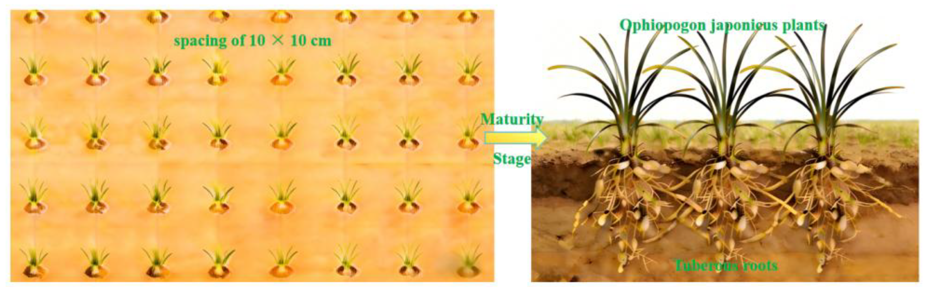
Ophiopogon japonicus was densely planted at 10 × 10 cm spacing between plants and rows. At maturity, the aboveground portion exhibited a tufted grass-like appearance with slender linear leaves. The extensive root system formed numerous spindle-shaped tuberous roots. Roots of adjacent plants intertwined, creating a tightly integrated root–soil complex. Figure 1 illustrates the planting system and morphological characteristics of Ophiopogon japonicus.
Figure 1.
Ophiopogon japonicus planting pattern and cross-section at harvest.
2.2. Overall Structure and Working Principle of the Root-Soil Separation Device
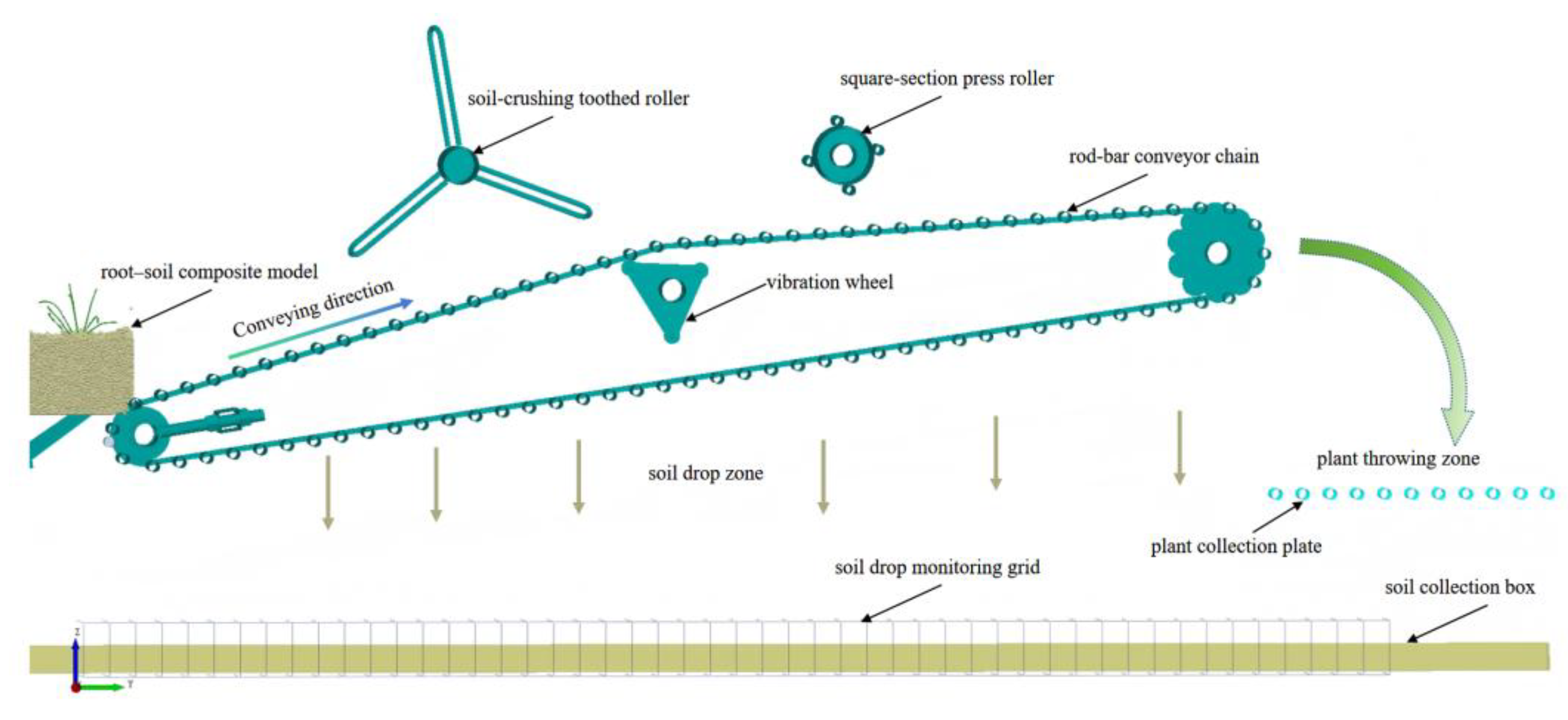
The Ophiopogon japonicus root–soil separation device serves as the core component of the self-propelled Ophiopogon japonicus harvester, collaborating with excavation, depth-limiting, lifting, collection, and mobility systems to complete harvesting operations. This device primarily comprises a chain rod conveyor chain, a vibrating wheel, a soil-crushing tooth roller, a square-edged pressure roller, and a frame, as illustrated in Figure 2.
Powered by the drive unit, the entire Ophiopogon japonicus harvester moves forward. Ophiopogon japonicus plants and soil layers are conveyed upward along the shovel surface by the digging device. They then pass through the vibrating chain rod grid between the digging and separation devices into the separation unit. The drive wheel provides power to maintain the rotation of the chain rod conveyor chain. At this point, the soil layer continues to move upward along the conveyor surface at a 25° angle. The rotating soil-crushing roller breaks up and preliminarily fragments the soil layer, dividing the initially fed, incompletely broken soil into discrete clumps. After passing through the roller, these clumps gradually approach the center of vibration of the chain rod conveyor chain. As the vibration wheel rotates, the chain rod conveyor chain vibrates perpendicular to the conveying surface. The soil clumps advance under repeated impacts and friction from the chain rod. Passing through the four-sided compression rollers, where the gap between the rollers and the chain rod conveyor chain is significantly narrower than that of the soil-breaking tooth rollers, resulting in more substantial compaction and friction on the root–soil composite. This removes soil firmly adhering to the Ophiopogon japonicus root system. Finally, the soil-root composite is conveyed via the chain rod conveyor chain to the lifting and collection devices, achieving complete separation of Ophiopogon japonicus roots from soil.
2.3. Key Component Structural Design
The chain rod conveyor chain consists of a chain rod, connecting belts, drive wheels, and idler wheels. To accommodate the row spacing of Ophiopogon japonicus and the front-end digging device, the conveyor chain width is designed at 1.3 meters. The spacing between the chain rods determines the risk of Ophiopogon japonicus loss and jamming. Using a sample of 20 Ophiopogon japonicus plants, the minimum gap value at rest, where plants did not fall through, was identified. Considering the conveying angle and rotational speed of the chain rod conveyor chain, the gap was empirically set at 0.6 to 0.8 times the minimum gap value, while ensuring it did not fall within the range where plants would become stuck. After on-site fine-tuning and accounting for manufacturing and assembly complexity, the final chain rod gap was set to 40 mm. Under heavy clay conditions, the typical experimental range for linear speeds of root crops such as potatoes is 0.8–2.4 m/s. Research indicates a recommended range of 1.0–2.2 m/s [14]. Ophiopogon japonicus is more susceptible to damage than potatoes, with impacts and drops causing root injury more readily. Drawing on prior research experience [15], a linear speed of 0.8–1.2 m/s was selected.
The vibrating wheel comprises triangular side plates, rolling bearings, and pins, with power transmitted via corresponding drive shafts. Research indicates that, for soil separation, the vibration amplitude and frequency of the vibrating wheel are best represented by peak acceleration values, as the ability to loosen, dislodge, and break up soil clods primarily depends on the magnitude of the vibration acceleration. Peak acceleration requirements vary significantly across different soil types. Sandy soils achieve high separation efficiency at 3 times the gravitational acceleration, while clay soils may require up to 8 times the gravitational acceleration for noticeable results [16]. Vibration direction also impacts root–soil separation. Based on the above analysis, the vibration amplitude range is selected as 15–25 mm, and the vibration frequency range as 8–12 Hz. The peak acceleration formula is:
where: apeak - Peak acceleration of the vibrating wheel, m/s²; f - Vibration frequency, Hz; A - Vibration amplitude, m.
The soil-crushing tooth roller consists of a drum fitted with six staggered U-shaped teeth, evenly distributed around the circumference. The axial distance between adjacent U-shaped teeth is 230 mm, with a circumferential angle of 120°. The digging depth is 20 cm, accounting for clearance between the drum and the upper soil layer, as well as between the tooth tips and the chain rod conveyor chain. The tooth length is designed at 220 mm. The four-sided compression roller comprises a central cylinder and four cylindrical edges arranged at 90° intervals around the periphery. With an outer diameter of 128 mm, it is positioned behind the chain rod conveyor chain.
The schematic diagram of the chain rod conveyor, chain, and soil-crushing tooth roller operation is shown in Figure 3. Taking point O as the coordinate origin, the position of the center of chain rod B is denoted as Eij. The coordinates of point Eij are recorded as (xa, ya), and the equation for the position of point Eij is:
During chain rod movement, the velocity change is:
where: A - Vibration amplitude, m; C - Constant representing vibration frequency; H - Height of chain rod above excavation base layer, m; - Excavation angle, °; v - Conveying speed along installation plane direction, m/s; L1- Horizontal distance from point O to chain rod B, m.
The chain rod’s motion trajectory combines linear movement along the conveying plane with reciprocating vibration perpendicular to it. Trajectory analysis reveals two primary operational phases: the striking zone during ascent and the loosening zone during descent. During the striking zone in the upward phase, the chain rod contacts the bottom soil layer, applying a striking force perpendicular to the layer surface. The chain rod sinks into the bottom soil layer, exerting a pulling force along the conveying plane while simultaneously applying thrust and friction to the soil layer. This disrupts the connections between root–soil composite units. During the loosening phase of the descent stage, the chain rod descends faster than the falling root–soil composite. This creates voids between the soil and the chain rod. As the root–soil composite falls, the entire soil layer gains loose space. The cycle completes when the chain rod rises again to strike and dislodge the root–soil composite.
2.4. Simulation of Root-Soil Separation Mechanism
2.4.1. Acquisition of Simulation Parameters
During the Ophiopogon japonicus harvest period, a five-point sampling method was employed within a1200 m² area and at a depth of 30 cm. Soil firmness was measured at 1498 kPa, and Ophiopogon japonicus plants along with their soil were collected. Soil moisture content was determined, yielding an average value of 19.5%. Soil density was measured using a ring knife and balance, with five measurements taken, yielding an average density of 1.26 g/cm³ for the test samples. The soil particle size was 5 mm, Poisson’s ratio was 0.26, and shear modulus was 0.96 GPa. The density of the soil-contacting vibrating chain rod was 7865 kg/m³, Poisson’s ratio was 0.3, and the shear modulus was 79 GPa.
Ophiopogon japonicus plants harvested during the harvesting period in Santai County, Sichuan Province, were collected for mechanical measurements. Five Ophiopogon japonicus plants were selected, with a measured plant density of 1021 kg/m³. Tensile load measurements were conducted using a universal testing machine. The breaking force of the Ophiopogon japonicus plant was 32.6 N. The Poisson’s ratio was calculated using formula (4), and the average Poisson’s ratio of the five samples was 0.35.
where: μ - Poisson’s ratio; Δw - transverse displacement, m; Δ1 - longitudinal displacement, m;
The elastic modulus was calculated using formula (5) as1.19 MPa.
where: E - elastic modulus; Δσ - stress, Pa;
The shear modulus is calculated using formula (6) as 5360 kPa
The rolling friction coefficient and collision recovery coefficient between the chain rod-plant, chain rod-soil, and soil-plant interfaces were measured using the inclined plane method. For parameters unattainable via experimental methods, DEM virtual parameters were calibrated using the superposition method. The collision recovery coefficient and rolling friction coefficient of Ophiopogon japonicus plants were calibrated using the bucket lift method, while soil-soil parameters were calibrated using the funnel method [17]. The simulation parameters required for modeling are shown in Table 1 and Table 2.
2.4.2. Discrete Element Modeling of Ophiopogon japonicus Plants and Soil Complexes
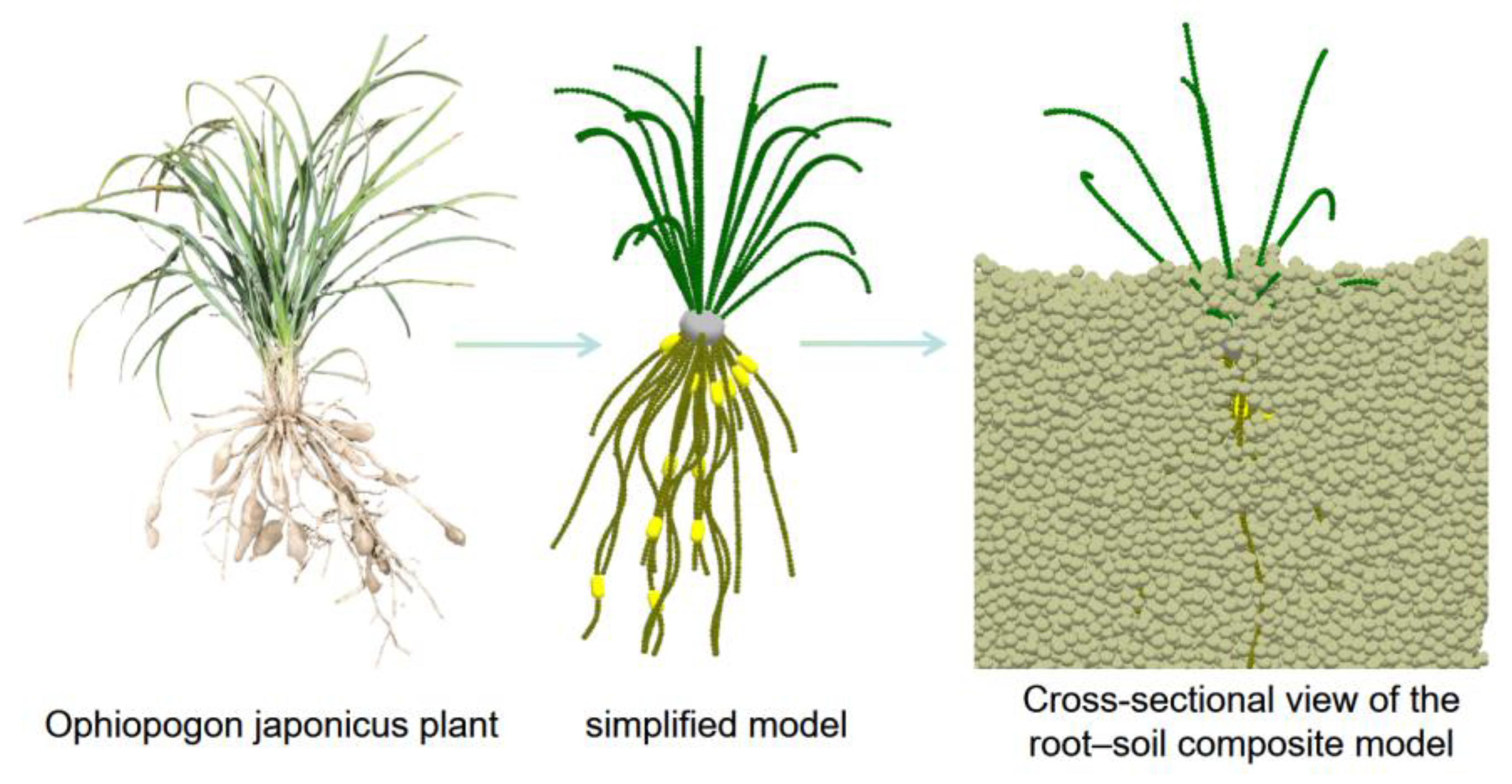
Morphological parameters of Ophiopogon japonicus plants, including plant height, leaf length, number of leaves, rhizome length, number of rhizomes, tuber size, and number of tubers. Simplify the model based on actual dimensions. Simplify the Ophiopogon japonicus plant model using NX 2312 to create the plant model and export point coordinates. Using the EDEM 2023 element particle function, discrete element particles were created for Ophiopogon japonicus leaves, roots, and fruits. The element particle module imported the spatial point coordinates of roots, leaves, and fruits to establish their respective models.
The root–soil separation device was modeled, simplifying structural elements like bolts, bearings, and washers while retaining core components: side plates, vibration chains, feed plates, plant collection grids, and soil collection boxes. Defined the chain rod motion as horizontal translation combined with vertical vibration.
The Hertz–Mindlin with JKR model was employed, suitable for moist materials such as soil, to characterize significant particle bonding and agglomeration due to moisture content [18]. Simultaneously configure the Hertz-Mindlin with the bonding model to simulate complex fracture and breakage phenomena. Under external forces, inter-particle bonding strength fails, leading to fragmentation and fracture [19]. The average spacing between Ophiopogon japonicus plants is 0.1m, with a harvesting depth of approximately 0.2m. Each soil unit of the root–soil composite has dimensions of 0.1m × 0.1m × 0.2m. The feeding simulation of root–soil composite units mimics the process of entering the conveyor chain via the digging bucket. These units are generated above the feed plate, and the initial conveying speed of the advancing plate is set to match the machine’s forward speed to feed the root–soil composite units to the root–soil separation device.
Figure 4.
Root-soil composite model construction.
2.4.3. Simulation Test Plan
Root-soil separation effectiveness is characterized by two metrics: Second, the change in the contact number between roots and soil post-separation. The final contact number serves as the primary analytical metric and can be multiplied by soil particle mass to yield plant soil-carrying capacity. Additionally, the motion patterns of the separation process are characterized by monitoring the displacement trajectory of the central plant particle and the forces acting on the chain rod.
Figure 5.
Method for Obtaining Simulation Parameter Results.
In the structural design and parameter calculation of key components, the conveying speed, vibration frequency, and vibration amplitude of the chain rod define the design range, with no clearly optimal key parameters identified. Single-factor experiments and response surface analysis were employed, with experimental factors listed in Table 3. The study examined the effects of conveying speed, vibration frequency, and amplitude on the contact number and the soil shedding distance at 80% soil shedding (hereafter referred to as D80), identifying the optimal structural parameters under the tested conditions.
2.5. Field Trial Validation Protocol
The trial was conducted in Santai County, Mianyang City, Sichuan Province (N31°10′, E105°10′, elevation 409m). Soil moisture content was 15.77%, and the average soil firmness at 0–25 cm depth was 1391 kPa. The trial plot measured 40m in total length and 10m in width. The Ophiopogon japonicus harvest trial referenced the national standard [20,21] and practical agronomic requirements for Ophiopogon japonicus harvesting. Field tests selected soil shedding rate and soil retention rate as evaluation metrics for the soil-separation device of the Ophiopogon japonicus harvester.
3. Results and Discussion
3.1. Patterns of Plant and Stem Changes
As shown in Figure 6, the trajectory from Point A to Point I represents the movement of the plant’s central node within the soil-separation device. Point A denotes the plant’s initial position, at which point the plant-soil simulation model was newly generated. Point I represents the final position the plant settles on the collection grid after the root–soil complex separates. The root–soil complex primarily exhibits small-range displacement within 20 mm along the X-axis, moves with quasi-uniform velocity along the Y-axis, and undergoes falling, translational, and vibrational motions along the Z-axis. The path from Point A to Point B represents the vertical descent of the root–soil complex onto the conveyor chain plane after generation, simulating the transfer process from the excavator bucket screen chain rod to the conveyor chain plane. Point B to Point C represents the initial movement distance of the soil-root composite on the vibrating chain rod conveyor chain plane. As indicated by the scale lines in the figure, the soil-root composite did not undergo significant deformation within the initial 100 mm, maintaining a relatively intact shape at this stage; the segment from Point C to Point D represents the coarse separation stage of the root–soil composite. Here, the composite undergoes significant fragmentation and deformation, with the soil layer splitting into larger clumps that fall through gaps as the vibrating chain strikes them. The line from point D to point F represents the delicate root–soil separation process. This stage primarily involves separating soil particles adhering to plant roots. Notably, at point E, the plant makes direct contact with the vibrating chain. Beyond point E, the plant’s vibration amplitude increases significantly as the initiating displacement is increased within a 20 mm range along the X-axis. This indicates a marked reduction in the amount of soil retained by the plant. Points F to I represent the ejection process, where the plant detaches from the vibrating chain and lands on the collection plate screen surface in front of it. Points G to I show the plant’s sliding and tipping motion on the collection screen surface, with point H marking the start of lateral tipping. The overall morphological changes from points A to I are illustrated in Figure 7.
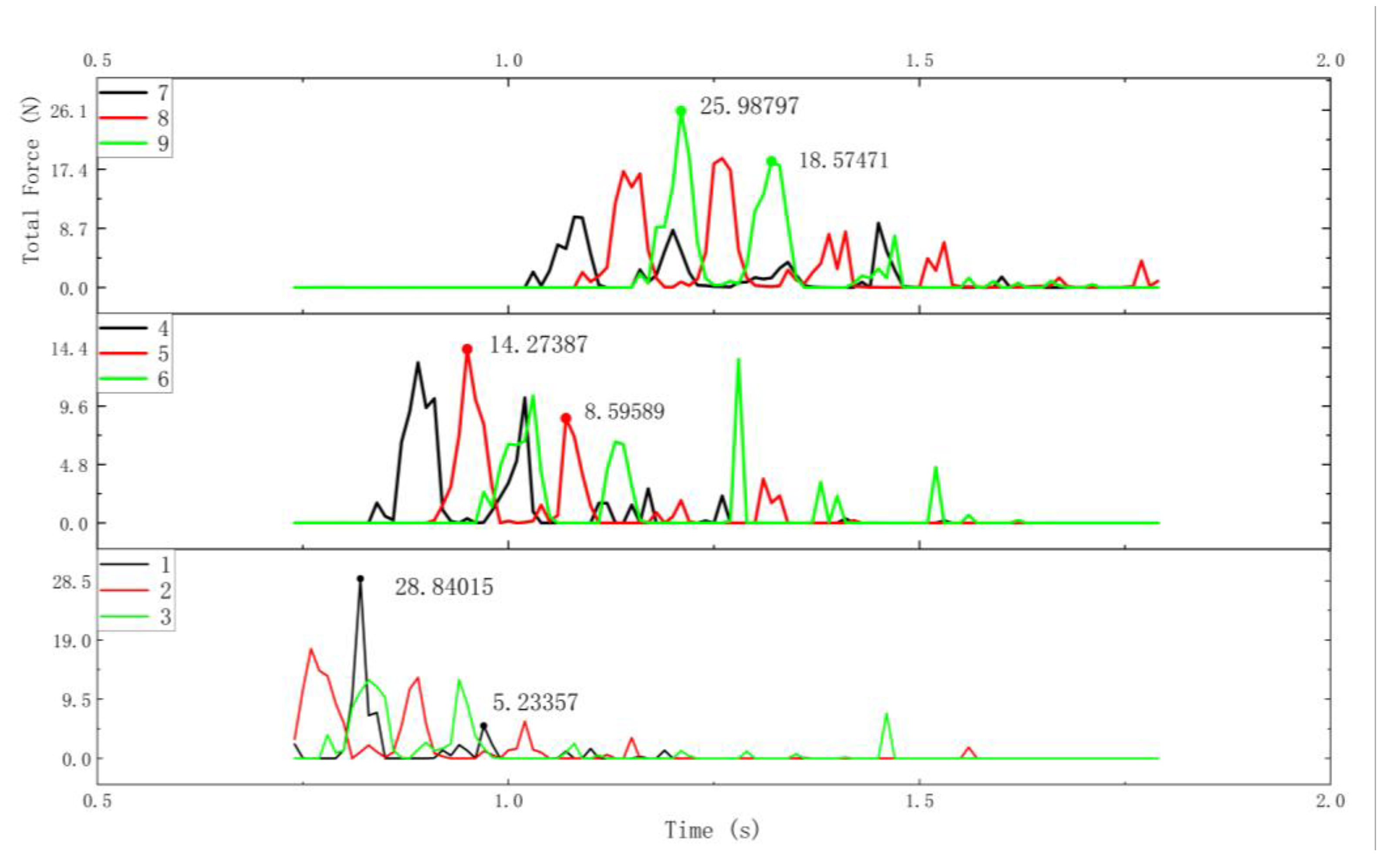
During root–soil separation, the chain rods employ a composite motion combining horizontal translational friction and vertical vibratory beating. Within each cycle, repeated beating and friction separate the root–soil complex. Using the key points in Figure 6 as divisions, the separation process is categorized as follows: vibratory separation of the semi-loosened complex while chain rods contact both soil and plant (D-E). During movement, the chain rod’s velocity significantly exceeds that of the root–soil complex, with each chain rod experiencing two distinct force peaks. During the initial overall beating phase of the root–soil complex, the 200 mm×200 mm Ophiopogon japonicus root–soil unit functions as a single entity, subjecting the chain rods to maximum stress. In the vibration separation phase of the semi-loose complex, where chain rods contact both soil and plant material, the plant roots have separated from the soil. At this stage, the soil is in a semi-loose state, with some soil having fallen through gaps between chain rods. Pressure on the chain rods gradually decreases. During the direct separation phase, most of the soil has fallen away, allowing the chain rods to strike plants directly. Plants exhibit pronounced vibration curves during this process. In the plant-ejection phase, chain rods bear only plant pressure.
Figure 8.
Force variation of a representative chain rod during beating cycles.
3.2. Effects of Vibration Frequency, Amplitude, and Conveying Speed on Separation Efficiency
Single-factor experiments were conducted using the following observational metrics: variations in soil deposition across different zones during root–soil complex separation, the distance at 80% soil deposition (D80), and the number of contacts between soil particles and plant particles. Vibration frequency tests were performed under conditions C=20 mm and A=1 m/s; Amplitude tests were conducted at B=10 Hz and A=1 m/s; conveying speed tests were conducted at B=10 Hz and C=20 mm.
Figure 9(a) shows the effect of frequency on the number of contacts. Analysis of the curve’s peak N_peak, end-residual, and decay rate k reveals: At 8 Hz: N_peak = 528, end-residual 0%, Decay rate k = 1.884 s⁻¹. At 10 Hz, the peak N_peak = 446, end-residual 0%, k = 1.292 s⁻¹. At 12 Hz, the peak N_peak = 573, end-residual 22.7%, k = 0.627 s⁻¹, exhibiting the slowest decay rate post-peak. At 12 Hz, the pattern of “higher and later peak + slower post-peak decay + significant residual” indicates longer and lower adhesion contact duration under high-frequency conditions. Although the peak at 8 Hz is slightly lower than at 12 Hz, it exhibits the fastest decay with zero residual, demonstrating greater effectiveness in reducing contact number.
Figure 9(b) shows the effect of amplitude on the number of contacts. At 15 mm, the curve exhibits 28.7% residual, a decay rate k=0.621 s⁻¹, and an area under the curve (AUC) of 920.5. For the 20 mm curve, residual area was 20.5% (lowest among the three curves), post-peak decay rate k = 0.681 s⁻¹ (fastest among the three curves), and AUC = 735.0 (lowest among the three curves). In the 25 mm curve, the residual was 24.4%, the post-peak decay rate k=0.562 s⁻¹, and the integrated area AUC=1008.8 was the highest among the three curves. The 20 mm curve simultaneously achieved the lowest cumulative adhesion strength (lowest AUC), the lowest residual adhesion, and the fastest post-peak decay rate, demonstrating the most efficient particle connection breakage. Although the 25 mm curve applied stronger excitation, it exhibited the highest AUC and slower decay, suggesting that high amplitude may induce more repeated contacts or ineffective follow-through, thereby reducing breakage efficiency.
Figure 9(c) shows the effect of conveying speed on the number of contacts. At 0.8 m/s, the residual contact number is 6.0%; k = 1.421 s⁻¹. At 1.0 m/s, residual contact number is 0% (optimal), k = 1.872 s⁻¹ (fastest). At 1.2 m/s, residual 3.2%, k=1.759 s⁻¹. Targeting “cleanness of terminal bond breakage,” 1.0 m/s is optimal with 0% residual and fastest decay. This indicates that bond breaking is not solely determined by residence time but also depends on the material’s relative motion state. Moderate speeds may achieve a better balance between “effective shearing/kneading” and “excessive trailing/tumbling.”
Figure 10(a) shows the effect of vibration frequency on soil particle distribution. At 8 Hz, D80 = 571 mm, with the front section (0–400 mm) accounting for 44.5% and the rear section (800–1000 mm) for 2.3%. At 10 Hz, D80 = 774 mm, with the front segment accounting for 20.1% and the rear segment 15.6%. At 12 Hz, D80 = 776 mm, with the front segment accounting for 17.0% and the rear segment 16.0%. The 8 Hz frequency significantly reduces D80 and suppresses rear segment soil deposition, indicating earlier and more concentrated soil detachment. The late-stage proportion in the 10–12 Hz range reached approximately 16%, indicating delayed soil detachment into the latter phase with pronounced trailing effects. This phenomenon aligns with the higher residual values and slower decay observed at 12 Hz in Figure 9(a), suggesting that higher frequencies did not translate into more effective shear de-bonding but instead reduced early-stage separation efficiency.
Figure 10(b) shows the effect of amplitude on the spatial distribution of fallen soil. For the 15 mm curve, D80 = 725 mm, the final segment accounts for 8.9%, and the total fallen soil volume is 4.738 kg. For the 20 mm curve, D80 = 774 mm, the final segment accounts for 15.6%, and the total fallen soil volume is 4.282 kg. For the 25 mm curve, D80 = 817 mm, with the tail segment accounting for 21.8% and total soil discharge at 3.410 kg. Increasing amplitude significantly shifts the soil discharge backward and exacerbates trailing (D80 continuously increases, trailing proportion rises markedly), while total soil discharge decreases. This indicates that excessive amplitude tends to enhance compound body trailing/throwing, reducing the “effective time window for soil passing through chain rod gaps.” Therefore, under the objective of “controlling soil discharge process advancement/trailing,” a smaller amplitude is more advantageous.
In Figure 10(c), which shows the effect of conveying speed on the spatial distribution of soil drops, the curve at 0.8 m/s has the shortest distance (D80 = 543 mm). The front section accounts for 49.3%, and the rear section for 1.3%, resulting in the lowest performance among the three curves. The total soil drop volume is 5.099, achieving the highest performance. At 1.0 m/s, D80 = 571 mm, with 44.5% distribution in the front section and 2.4% in the rear section. At 1.2 m/s, D80 = 565 mm, with 48.3% distribution in the front section and 2.7% in the rear section. The 0.8 m/s curve significantly advances soil detachment and reduces end-stage soil loss, demonstrating a typical “residence time-cumulative excitation” effect: reduced velocity increases exposure time, enabling earlier soil release. This conclusion does not contradict Figure 9(c) but reveals a multi-objective trade-off: while 0.8 m/s optimizes “detachment advancement,” it yields an inferior “clean final fracture” compared to 1.0 m/s.
Integrating Figure 9 and Figure 10 shows that under single-factor conditions, “early soil release/late-stage suppression” (characterized by D80 and late-stage proportion) does not always align with “clean final fracture state” (characterized by residual proportion and post-peak decay rate). Low transport velocity significantly improves early soil release, but moderate velocity is more favorable for final fracture. Both amplitude and frequency exhibit non-monotonic window characteristics. Therefore, subsequent response surfaces should model the A–B–C coupling to obtain optimal parameter combinations that balance low residual fractures with low D80/low terminal sedimentation volume within a multi-objective framework.
3.3. Interaction Analysis
As shown in Table 5 (contact number results), the overall model is significant (p = 0.0093 < 0.05), indicating that the established response surface model effectively explains variations in contact number. Among the main effects, frequency B had the most significant impact on contact number (F = 10.15, p = 0.0097), followed by amplitude C (F = 6.44, p = 0.0295). Conveying speed A showed a trend of influence but was not significant at the 0.05 level (p = 0.0973). Among the interaction terms, A×C was substantial (p = 0.0479), indicating a coupled effect between conveying velocity and amplitude. A×B and B×C were marginally significant (p = 0.0731) within the experimental range, suggesting an interaction trend present but weaker than A×C. The lack of significance in the term for model misfit (p = 0.8002) indicates good model fit, suitable for response surface interpretation and parameter optimization.
Table 4 (D80 results analysis) shows the model is highly significant (p<0.0001), indicating strong predictive capability for variations in soil deposition volume. The main effects of factors A (conveying speed), B (vibration frequency), and C (vibration amplitude) were all highly significant (p<0.01). The interactions AB and BC were also substantial, as were the quadratic terms A² and B². This indicates these factors exert both linear and nonlinear influences on soil discharge volume. The lack of significance for the lack-of-trial term (p=0.2593) confirms the model’s good fit.
Analysis of both response metrics indicates that amplitude is the most critical factor, with the AB interaction being significant in both models. The soil discharge model exhibits more complex response characteristics, incorporating additional significant factors and quadratic effects. During optimization, prioritize adjusting the amplitude parameter while considering the interaction between conveying speed and vibration frequency.

Table 4.
Response Surface Experimental Design and Results.
| No. | Conveying speed (m/s) | Vibration frequency (Hz) | Amplitude (mm) | Contact number | D80 (mm) |
|---|---|---|---|---|---|
| 1 | 1 | 0 | -1 | 18 | 690 |
| 2 | -1 | -1 | 0 | 39 | 600 |
| 3 | 0 | -1 | -1 | 36 | 555 |
| 4 | 1 | -1 | 0 | 30 | 660 |
| 5 | 0 | 0 | 0 | 16 | 765 |
| 6 | 0 | 1 | 1 | 36 | 780 |
| 7 | 0 | 0 | 0 | 33 | 735 |
| 8 | 0 | 0 | 0 | 32 | 735 |
| 9 | 1 | 0 | 1 | 43 | 795 |
| 10 | 0 | -1 | 1 | 34 | 780 |
| 11 | 0 | 0 | 0 | 28 | 735 |
| 12 | -1 | 1 | 0 | 10 | 630 |
| 13 | 0 | 0 | 0 | 33 | 735 |
| 14 | -1 | 0 | 1 | 17 | 720 |
| 15 | -1 | 0 | -1 | 19 | 570 |
| 16 | 1 | 1 | 0 | 25 | 795 |
| 17 | 0 | 1 | -1 | 14 | 675 |
Table 5.
contact number results.
| Source | Sum of Squares | df | Mean Square | F-value | p-value |
|---|---|---|---|---|---|
| Model | 1186 | 6 | 197.67 | 5.51 | 0.0093 |
| A | 120.13 | 1 | 120.13 | 3.35 | 0.0973 |
| B | 364.5 | 1 | 364.5 | 10.15 | 0.0097 |
| C | 231.13 | 1 | 231.13 | 6.44 | 0.0295 |
| AB | 144 | 1 | 144 | 4.01 | 0.0731 |
| AC | 182.25 | 1 | 182.25 | 5.08 | 0.0479 |
| BC | 144 | 1 | 144 | 4.01 | 0.0731 |
| Residual | 359.06 | 10 | 35.91 | ||
| Lack of Fit | 149.86 | 6 | 24.98 | 0.4776 | 0.8002 |
| Pure Error | 209.2 | 4 | 52.3 |
Table 6.
Analysis of D80 Results.
| Source | Sum of Squares | df | Mean Square | F-value | p-value |
|---|---|---|---|---|---|
| Model | 93,558.31 | 9 | 10395.37 | 40.68 | < 0.0001 |
| A | 22050.00 | 1 | 22050.00 | 86.29 | < 0.0001 |
| B | 10153.13 | 1 | 10153.13 | 39.73 | 0.0004 |
| C | 42778.12 | 1 | 42,778.12 | 167.41 | < 0.0001 |
| AB | 2756.25 | 1 | 2756.25 | 10.79 | 0.0134 |
| AC | 506.25 | 1 | 506.25 | 1.98 | 0.2021 |
| BC | 3600.00 | 1 | 3600.00 | 14.09 | 0.0071 |
| A2 | 5686.58 | 1 | 5686.58 | 22.25 | 0.0022 |
| B2 | 4585.26 | 1 | 4585.26 | 17.94 | 0.0039 |
| C2 | 464.21 | 1 | 464.21 | 1.82 | 0.2197 |
| Residual | 1788.75 | 7 | 255.54 | ||
| Lack of Fit | 1068.75 | 3 | 356.25 | 1.98 | 0.2593 |
| Pure Error | 720.00 | 4 | 180.00 | ||
| Cor Total | 95,347.06 | 16 |
Figure 11(a) illustrates the combined variation trend of contact number with conveying speed A and vibration frequency B when amplitude C is set at the central level. The response surface exhibits more pronounced fluctuations along the vibration frequency direction, indicating that within the experimental range, vibration frequency B exerts a more substantial modulating effect on contact number. This aligns with the significant B effect in the ANOVA (p=0.0097). In contrast, the influence of A is relatively moderate (p=0.0973), primarily manifesting as an “amplification/attenuation” effect on the amplitude of contact number variation across different B levels, rather than a stable monotonic main effect.
Figure 11(b) further reveals the interaction characteristics between A and B. At different vibration frequency levels, the slope of the variation in contact number with A differs (the lines are not parallel), indicating that the velocity effect depends on frequency. However, statistically, A×B shows only a marginally significant trend (p=0.0731), suggesting that within the experimental range, the interaction effect is weaker than the critical factors. From an engineering perspective, A×B can be interpreted as an “operating condition matching term”: unreasonable speed–frequency combinations elevate contact number. Thus, while optimizing these factors requires considering their synergy, their priority is lower than that of the main effects B and C and the interaction A×C.
Figure 11(c) evaluates the regression model’s reliability in fitting and predicting the contact number. Scatter points predominantly cluster around the 1:1 line, with an insignificant misfit (p=0.8002), indicating that the model effectively explains the experimental data and is suitable for response surface trend analysis and subsequent parameter optimization. This conclusion is corroborated by the model’s overall significance (p=0.0093).
Collectively, Figure 11(a)–(c) reveal that within the experimental range, contact number is primarily governed by the significant main effects of vibration frequency B and amplitude C (p=0.0097, p=0.0295, respectively), alongside a significant interaction effect A×C (p=0.0479). This indicates that “the influence of conveying speed must be examined at different amplitude levels,” as changes in speed alter the particle distribution through amplitude variations.0.0295), alongside a significant A×C interaction effect (p=0.0479). This indicates that “the influence of conveying velocity must be discussed at different amplitude levels,” meaning that velocity changes amplify or attenuate the effect of amplitude on bond breaking/desorption by altering particle relative motion and recontamination opportunities. In contrast, A×B and B×C showed only marginal significance (p=0.0731), suggesting they influence contact number as “local improvements or deteriorations arising from combined matching” rather than as dominant factors. Based on these patterns, the priority path for contact number optimization should be: first, establish a baseline range with a low contact number at vibration frequency B and amplitude C, then, within this range, finely match transport velocity A based on the A×C relationship to avoid the undesirable scenario where “amplitude adjustment enhances re-contact but causes contact number rebound.”
Figure 12(a) (A×B response surface, C=center): D80 generally increases with rising A and B, and the AB interaction is significant (p=0.0134). This indicates that simultaneously increasing velocity and frequency amplifies the risk of post-impact displacement/tailing (where soil deposition becomes more concentrated in the latter distance segment).
Figure 12(b) (B×C response surface, A=center): Amplitude C’s effect on D80 is modulated by vibration frequency B, with significant BC interaction (p=0.0071). This implies that the extent to which “increased amplitude causes delayed soil deposition” varies across frequencies, with high-frequency conditions more likely to exacerbate delayed deposition and trailing.
Figure 12(c) (Prediction-Measurement Consistency + Nonlinearity): The model fits well with insignificant misfit (p=0.2593). Both A² and B² are significant, indicating a pronounced nonlinear curvature region for D80—the response of soil deposition distance to A and B is not uniformly linear, but exhibits heightened sensitivity within specific intervals.
D80 is significantly influenced by A, B, and C together, with AB and BC interactions and A² and B² nonlinearities. Compared to the number of connecting bonds, the D80 process is more “complex” and more prone to “delayed/tail amplification zones.”
3.4. Key Parameter Optimization
To enhance the separation efficiency of the root–soil separation device during operation, dual-objective optimization was performed on experimental factors A (conveying speed), B (vibration frequency), and C (vibration amplitude). This ensured minimal contact number and soil drop distance while identifying their optimal configuration combination. Using Design-Expert software to solve the mathematical model, the optimal configuration combination was determined to be a conveying speed of 0.80 m/s, a vibration frequency of 12.00 Hz, and an amplitude of 15.00 mm. At this setting, the final soil drop distance was 563.25 mm, the contact number was approximately 6, and calculations based on particle mass indicated that the soil particles adhering to the plant were 0.0096 kg.
3.5. Field Trial Results
Field trials were conducted at a conveying speed of 0.80 m/s, a vibration frequency of 12.00 Hz, and an amplitude of 15.00 mm. Figure 13 shows the field test equipment and the harvest results for Ophiopogon japonicus. Soil loss per unit area was obtained by excavating one unit of Ophiopogon japonicus root–soil composite from the field. The equipment was placed in an open, clean area, and the root–soil composite was manually fed into the test apparatus. Data were acquired by measuring the soil mass in the collection area shown in Figure 13(a). The soil-attached mass of Ophiopogon japonicus plants was determined by measuring the weight of soil adhering to the plants, as shown in Figure 13(c).
Combining Figure 14(a)–(d) shows that the simulation results generally agree with the field experiments in terms of soil deposition distribution, characteristic distance (D80), and separated soil volume. The zoned soil deposition comparison (Figure 14(a)) indicates high consistency within the primary deposition range (200–800 mm): the relative errors for the 200–400, 400–600, and 600–800 mm zones are 1.47%, 1.13%, and 0.25%, respectively, suggesting that the model captures the dominant soil-deposition process driven by chain rod vibration and transport. Larger deviations occur in the boundary zones (0–200 mm and 800–1000 mm), with relative errors of 13.64% and 28.11%, respectively. This end-segment deviation is likely due to low baseline soil discharge in the terminal sections (minor absolute differences translating into significant relative errors) and field randomness (aggregate fragmentation, secondary rolling/falling, and moisture/adhesion fluctuations). Despite these local-ized discrepancies, the overall mass prediction remains accurate: the simulated total is 4.6746 kg versus a field total of 4.7100 kg (absolute error 0.0354 kg; relative error 0.75%).
Second, the cumulative soil deposition curve and the D80 index (Figure 14(b)) further validate the consistency of spatial distribution characteristics. The simulated and field cumulative curves closely align near the 0.8 cumulative level, corresponding to D80_sim = 571.3 mm and D80_field = 575.3 mm. The absolute error for D80 is only 4.05 mm, with a relative error of 0.70%. This demonstrates that the model not only matches total soil deposition but also accurately locates the critical distance of the “80% soil deposition concentration zone,” providing reliable quantitative evidence for matching the structural layout of separation zones with collection area dimensions. The consistency between the simulated and measured scatter plots in Figure 14(c) further demonstrates that the overall data for each partition approach the 1:1 line, with deviations primarily occurring in the initial and final segments. This statistically confirms that the error exhibits distinct segmental characteristics.
In terms of separation effectiveness, incorporating carry-soil mass in field measurements compensates for the “plant-residual soil” dimension (Figure 14(d)). The mean carry-soil mass measured across field replicates was 0.01084 kg (≈10.84 g), ranging from 0.0098 to 0.0120 kg, with a standard deviation of 0.00097 kg and a coefficient of variation of 8.96%. This indicates that while the indicator exhibits some field variability, it remains generally controllable. The presence of soil carryover also mechanistically explains the larger errors in the terminal section: although soil deposition is minimal in the terminal range (800–1000 mm), this section is more susceptible to satisfactory soil adhesion, re-contact, and secondary shedding, amplifying relative errors in the “tailing” zone. In summary, Figure 14(a)–(c) demonstrate that the simulation reliably predicts soil deposition rates and spatial distribution characteristics. Figure 14(d) further supports the field separation effectiveness by examining residual soil adhesion. Current errors primarily concentrate in the initial and final segments, representing explainable deviations resulting from the combined effects of field randomness and boundary conditions. Overall, the simulation model exhibits high engineering applicability and validated credibility.
4. Conclusions
(1) Addressing the operational demands of Ophiopogon japonicus harvesting in heavy clay soils—characterized by high soil carryover and strong soil-root adhesion—a root–soil separation device combining variable-gap soil-crushing teeth rollers with a vibrating chain rod-and-chain conveyor system was designed. A coupled soil-plant-machine discrete element model was established, providing a unified analytical platform for elucidating separation mechanisms and optimizing parameters.
(2) Using contact number and D80 as core evaluation metrics, a response surface method mapped the relationship between operational parameters (conveying speed, vibration frequency, and amplitude) and separation effectiveness. This systematically analyzed the influence patterns of main effects and interactions on “adhesive contact weakening” and “forward displacement/end-stage suppression of soil distribution.”Within a dual-objective optimization framework, a parameter combination balancing both metrics was obtained. The simulation predicted a D80 of 563.25 mm and a contact number of approximately 6 for this combination. Further conversion to particle mass indicated plant-attached soil mass of about 0.0096 kg, demonstrating that this parameter set reduces contact adhesion while suppressing soil displacement and trailing.
(3) Field validation at 0.80 m/s, 12.00 Hz, and 15.00 mm operating conditions yielded an average soil carryover of 0.012 kg per separated plant. Deviations primarily stemmed from fluctuations in field soil moisture and cohesion, natural variations in root–soil complexes, and equipment manufacturing/assembly tolerances and operational disturbances. Overall, simulation and field results align in magnitude and trend, demonstrating the engineering applicability of the discrete element model and response surface optimization. Future improvements in prediction accuracy and generalization capability can be achieved through calibration of soil cohesion parameters, modeling of aggregate breakup thresholds, and recontact processes.
Author Contributions
Conceptualization, Zhi’an Zheng and Min Wu; methodology, Aichao Li; validation, Aichao Li, Quanhe Yang. and Fuzeng Zhang.; formal analysis, Aichao Li and Lei Gao; investigation, Zhi’an Zheng.; resources, Min Wu.; data curation, Aichao Li.; writing—original draft preparation, Aichao Li.; writing—review and editing, Zhi’an Zheng.; visualization, Min Wu.; supervision, Aichao Li.; project administration, Zhi’an Zheng.; funding acquisition, Zhi’an Zheng. All authors have read and agreed to the published version of the manuscript.
Funding
This research was funded by the National Key R&D Program of China (grant number 2024YFC3506804). Supported by the earmarked fund for CARS-21.
Institutional Review Board Statement
Not applicable.
Data Availability Statement
Data are reported within the article.
Conflicts of Interest
The authors declare no conflicts of interest.
References
- State Pharmacopoeia Commission of the People’s Republic of China. Pharmacopoeia of the People’s Republic of China: Volume I; China Pharmaceutical Science and Technology Press: Beijing, 2025. [Google Scholar]
- Zhang, Wanyue; Hu, Hong; Hu, Zhichao; Wu, Ziqiang; Chen, Jun. Research Status and Development Trends of Potato-Soil Separation Technology. Agricultural Science and Technology 2025, 45, 43–47. [Google Scholar] [CrossRef]
- Liu, C.; Ma, Z.; Wang, S.; Zhao, L.; Xing, L. Research Status and Progress of Potato-Soil Separation Device in Potato Harvester. Academic Journal of Science and Technology 2025, 15, 119–123. [Google Scholar] [CrossRef]
- Zhang, X.; Liu, J.; Zhang, C.; Zhao, Y.; Du, X.; Zhang, X.; Liu, J.; Zhang, C.; Zhao, Y.; Du, X. Design and Experimentation of Small Potato Harvester for Heavy Soil in Hilly and Mountainous Areas. Agronomy 2024, 14. [Google Scholar] [CrossRef]
- Wu, B.; Huang, T.; Qiu, X.; Zuo, T.; Wang, X.; Xie, F.; Wu, B.; Huang, T.; Qiu, X.; Zuo, T.; et al. Design and Experimental Study of Potato-Soil Separation Device for Sticky Soil Conditions. Applied Sciences 2021, 11. [Google Scholar] [CrossRef]
- Tao, G.; Zhang, Z.; Yi, S.; Xia, C.; Ma, Y. Design and Experiment of Oscillating Screen Root-Soil Separation Device for Isatis Root Harvester. Transactions of the Chinese Society of Agricultural Machinery 2022, 53, 109–119. [Google Scholar]
- Wang, F. A.; Wen, B.; Xie, X. H.; Xie, K. T.; Guo, S. W.; Zhang, Z. G. Analysis of Working Mechanism and Parameter Optimization of Conveying and Separating Device for Notoginseng Harvester. Transactions of the Chinese Society of Agricultural Machinery 2023, 54, 201–211. [Google Scholar]
- Wu, Z.; Sai, Y.; Xie, K.; Zhang, Z.; Guo, R.; Wang, P. Optimization of Vibration Point Position for Notoginseng Separation Device Based on DEM-MBD Simulation. Transactions of the Chinese Society of Agricultural Machinery 2025, 56, 264–274. [Google Scholar]
- Pan, Y.; Yang, R.; Zhang, H.; Zhang, J.; Zha, X.; Qiu, Z.; Wu, M. Experiment and Optimization of the Potato-Soil Separation and Conveying Device for a Harvester Using RecurDyn-EDEM Coupling Simulation. International Journal of Agricultural and Biological Engineering 2025, 18, 149–156. [Google Scholar]
- Yan, Shuai; Cui, Qingliang; Yanqing, Zhang; Guang, Li; Zhihong, Zhao; Nan, An. Design and Experiment of a Drum-Type Root-Soil Separation Test Bench for Codonopsis Harvesting. Journal of Gansu Agricultural University 2023, 58, 226–234. [Google Scholar] [CrossRef]
- Wang, C.; Li, P.; Zhao, Z.; Pan, W.; Han, Q.; He, Z.; Yang, M.; Zhang, Z. Performance Analysis on Root-Soil Separation of Panax Notoginseng Using DEM-CFD Method and Air-Jet System. Computers and Electronics in Agriculture 2025, 239, 111050. [Google Scholar] [CrossRef]
- Liu, W. R.; Zhang, G. Z.; Liu, H. P.; Zhou, Y.; Wang, H. C.; Pei, L.; Li, Z. H. Design and Testing of Centrifugal Rotating Root-Soil Separation Device for Taro Harvester. Transactions of the Chinese Society for Agricultural Engineering 2024, 40, 14–26. [Google Scholar]
- Luo Jun; Liu Yu; Jiang Huixia; Zhao Bangtai; Liu Bo; Guo Jia; Ye Jianghong; Mei Linsen; Li Yun; Guo Xi. Design Study of Soil Separation Device for Mechanized Harvesting of Ophiopogon Root Tubers. Southern Agricultural Machinery 2022, 53, 1–4.
- Lu Jinqing; Sun He; Dui Han; Peng Mannan; Yu Jiayu. Improved Design and Testing of Separation and Conveying Device for Potato Digger in Heavy Clay Soil. Transactions of the Chinese Society of Agricultural Machinery 2017, 48, 146–155.
- Li Aichao; Zheng Zhi’an; Huang Luqi; Gao Lei; Cui Baocong; Wei Qing. Design and Testing of a Front-Mounted Digging Small Track-Type Ophiopogon Harvesting Machine. Research in Agricultural Mechanization 2024, 46, 58–65. [CrossRef]
- Rodriguez Hurtado, L. Simulation and Testing of a Vibrating Digger Blade for Root Crops. Doctor of Philosophy, Louisiana State University and Agricultural & Mechanical College.
- Fang, W.; Wang, X.; Han, D.; Zang, N.; Chen, X.; Ohiemi, I.E. Parameter Optimization and Disturbance Analysis of the Film Picking Device of the Chain-Type Plough Layer Residual Film Recovery Machine Based on DEM-MBD Coupling. Computers and Electronics in Agriculture 2024, 222, 109041. [Google Scholar] [CrossRef]
- Cheng, J.; Zheng, K.; Xia, J.; Liu, G.; Jiang, L.; Li, D.; Cheng, J.; Zheng, K.; Xia, J.; Liu, G.; et al. Analysis of Adhesion between Wet Clay Soil and Rotary Tillage Part in Paddy Field Based on the Discrete Element Method. Processes 2021, 9. [Google Scholar] [CrossRef]
- Sun, K.; Yu, J.; Zhao, J.; Liang, L.; Wang, Y.; Yu, Y. A DEM-Based General Modeling Method and Experimental Verification for Wheat Plants in the Mature Period. Computers and Electronics in Agriculture 2023, 214, 108283. [Google Scholar] [CrossRef]
- NY/T 3481-2019; Rhizome Chinese Medicinal Materials Harvesters Traditional Specification of Quality Evaluation. Ministry of Agriculture and Rural Affairs of the People’s Republic of China: Beijing, China, 2019.
- DG/T 189-2024; Rhizome Chinese Medicinal Materials Harvesters. Ministry of Agriculture and Rural Affairs of the People’s Republic of China: Beijing, China.
Figure 2.
Schematic diagram of the Ophiopogon japonicus root–soil separation device. 1 chain rod conveyor chain, 2 Soil-crushing tooth roller, 3 Vibrating wheel, 4 Square-edged pressure roller, 5 Frame.
Figure 2.
Schematic diagram of the Ophiopogon japonicus root–soil separation device. 1 chain rod conveyor chain, 2 Soil-crushing tooth roller, 3 Vibrating wheel, 4 Square-edged pressure roller, 5 Frame.
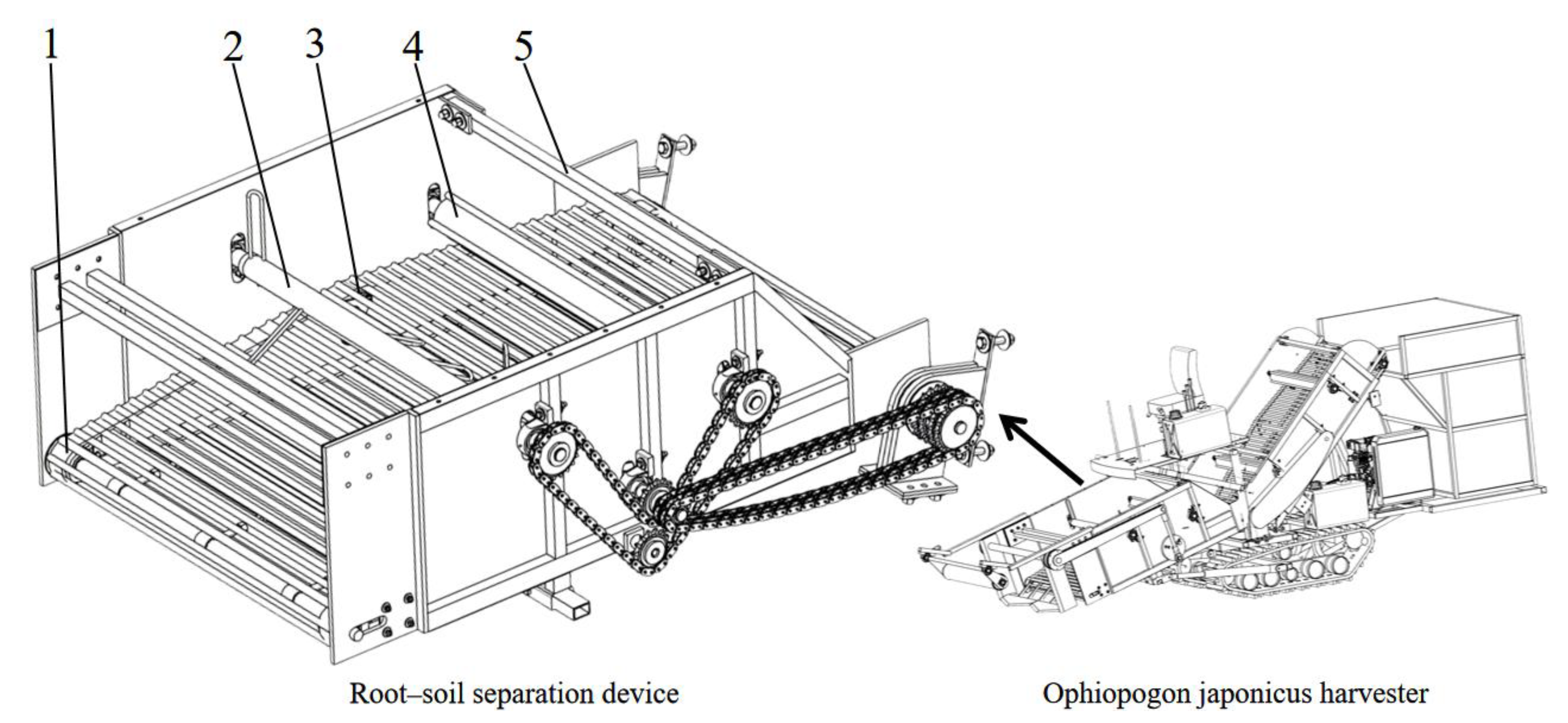
Figure 3.
Schematic of chain rod motion and soil layer response.
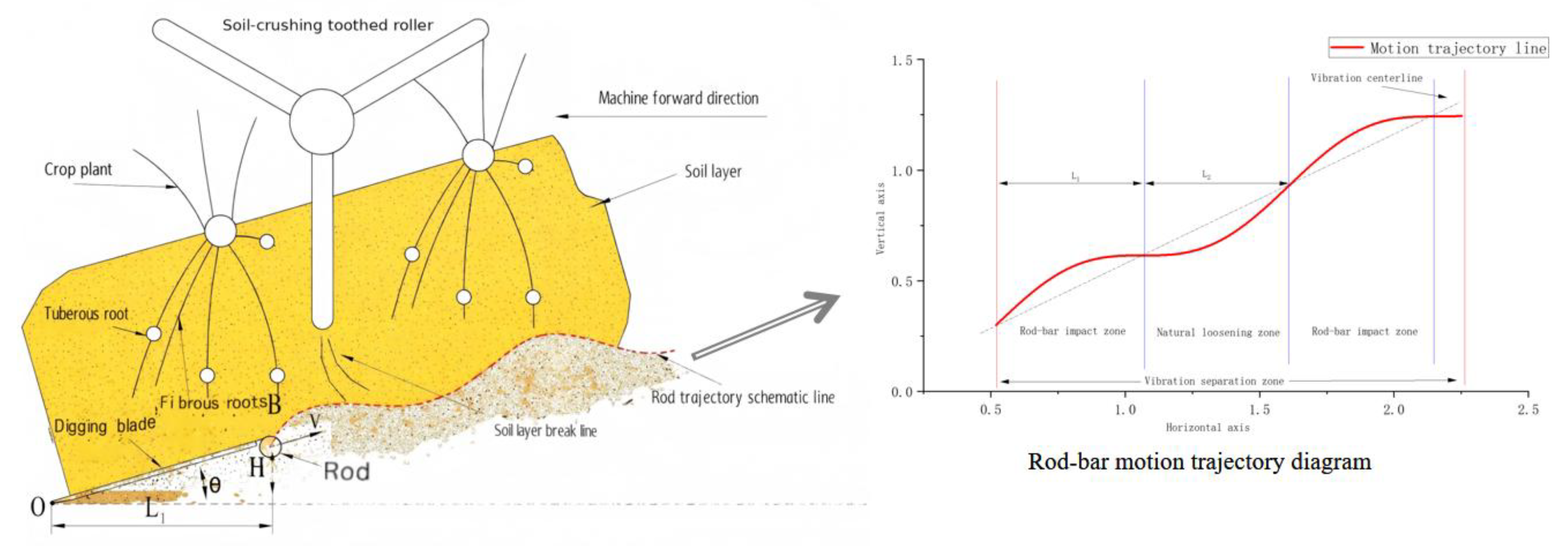
Figure 6.
Spatial trajectory of the plant centroid during separation.
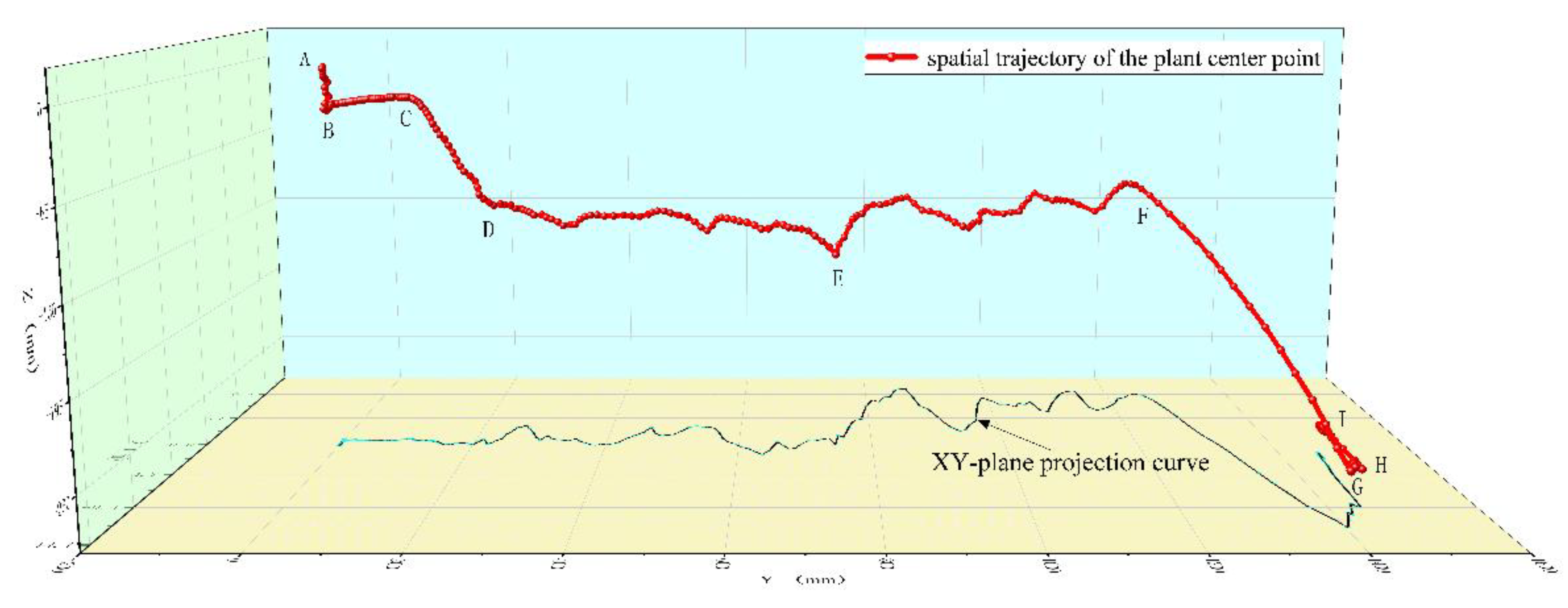
Figure 7.
Soil morphology evolution during separation.
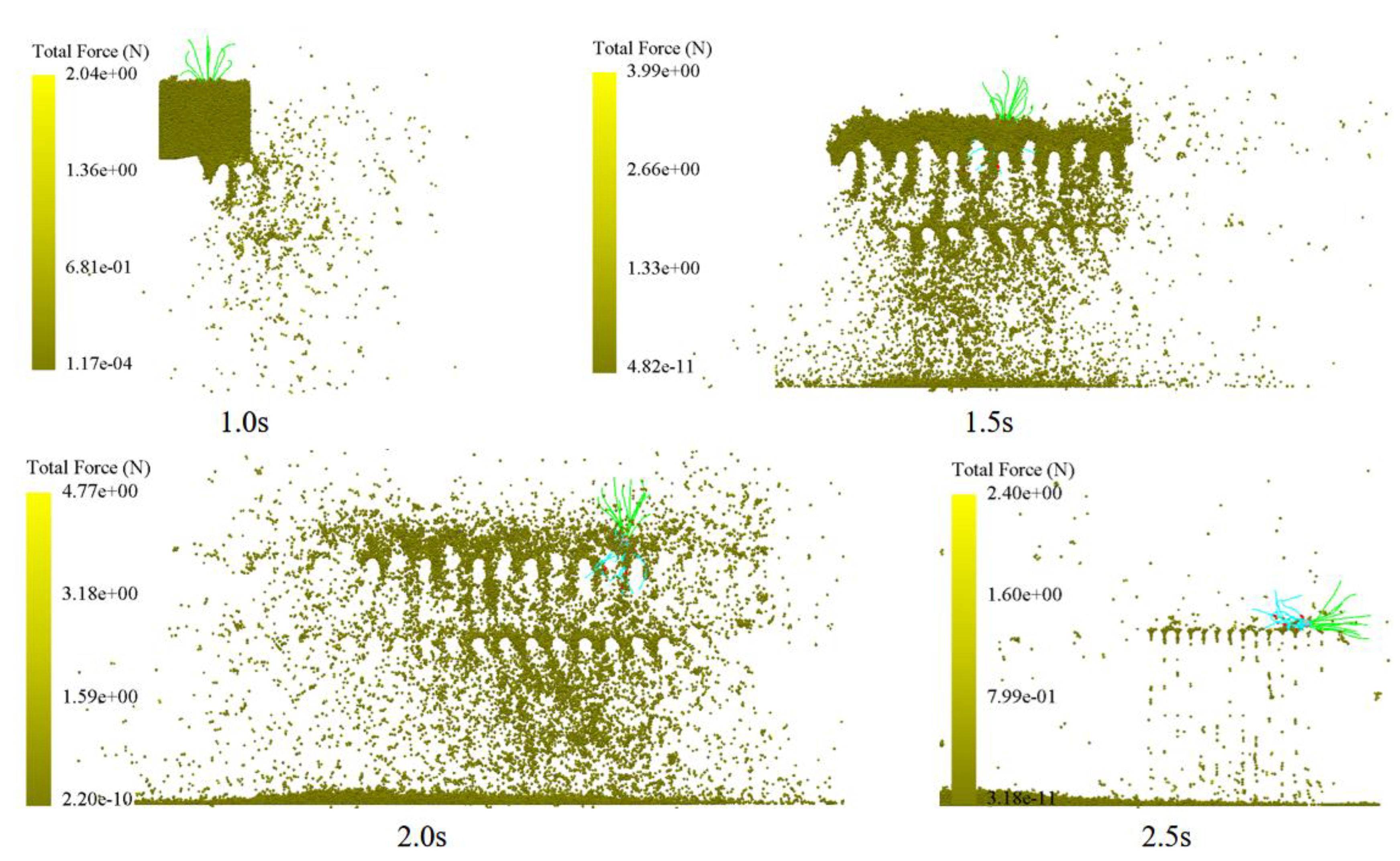
Figure 9.
Temporal variation in contact number between soil and plant particles under single-factor conditions: (a) Vibration frequency effect (amplitude 20 mm, conveying speed 1.0 m/s); (b) Amplitude effect (frequency 10 Hz, conveying speed 1.0 m/s);(c) Conveying speed effect (vibration frequency 10 Hz, amplitude 20 mm). Contact number characterizes the number of contacts between soil and plant particles within the root–soil composite. Its temporal decay reflects the fracture and release processes occurring during separation.
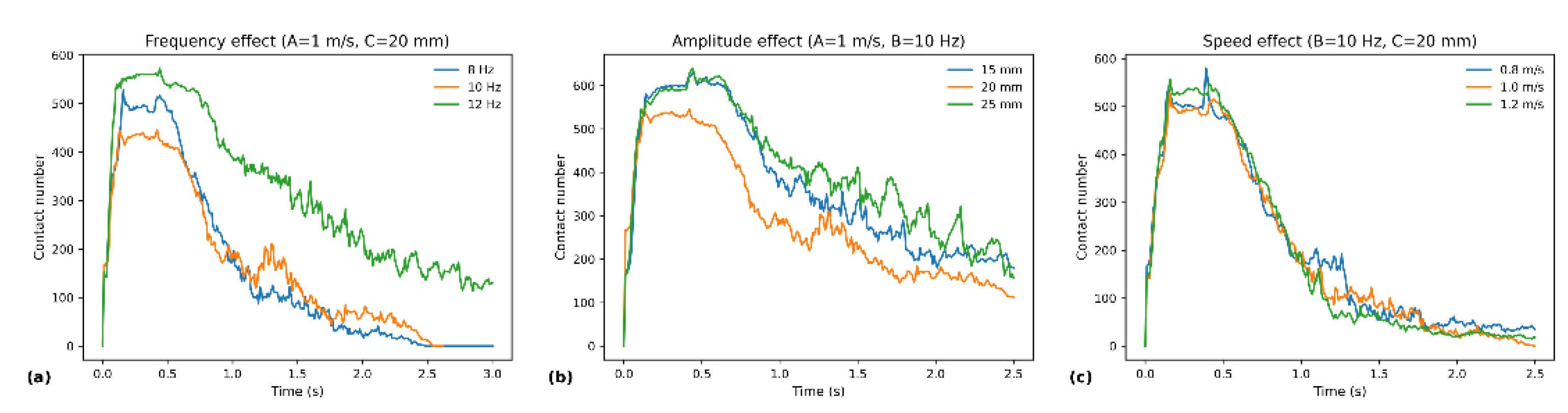
Figure 10.
Distribution of fallen-soil mass across distance intervals (0–200, 200–400, 400–600, 600–800, 800–1000 mm) during root–soil separation under different single-factor conditions: (a) Effect of vibration frequency (amplitude 20 mm, conveying speed 1.0 m/s);(b) Amplitude effect (vibration frequency 10 Hz, conveying speed 1.0 m/s); (c) Conveying speed effect (vibration frequency 10 Hz, amplitude 20 mm). The soil drop distribution characterizes the spatial location and “leading/tailing” characteristics of the soil detachment process: a higher proportion of soil drops in the initial range and fewer in the final range (800–1000 mm) indicates more complete separation and weaker tailing.
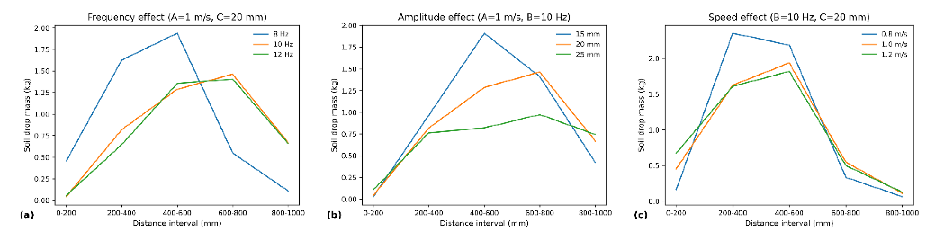
Figure 11.
Interaction effects and model fitting for contact number in the three-factor response surface. (a) Response surface of contact number versus conveying speed A and vibration frequency B (amplitude C set at central level); (b) A×B interaction plot (C set at central level);(c) Comparison of model predictions versus measured values to assess fitting consistency. Analysis of variance indicates the contact number model is significantly significant overall (p = 0.0093), with vibration frequency B (p = 0.0097) and amplitude C (p = 0.0295) as important influencing factors, and the A×C interaction term is essential (p = 0.0479); The A×B and B×C interactions showed marginal significance trends within the experimental range (p = 0.0731). The lack-of-trial term was not significant (p = 0.8002), indicating a reliable model fit.
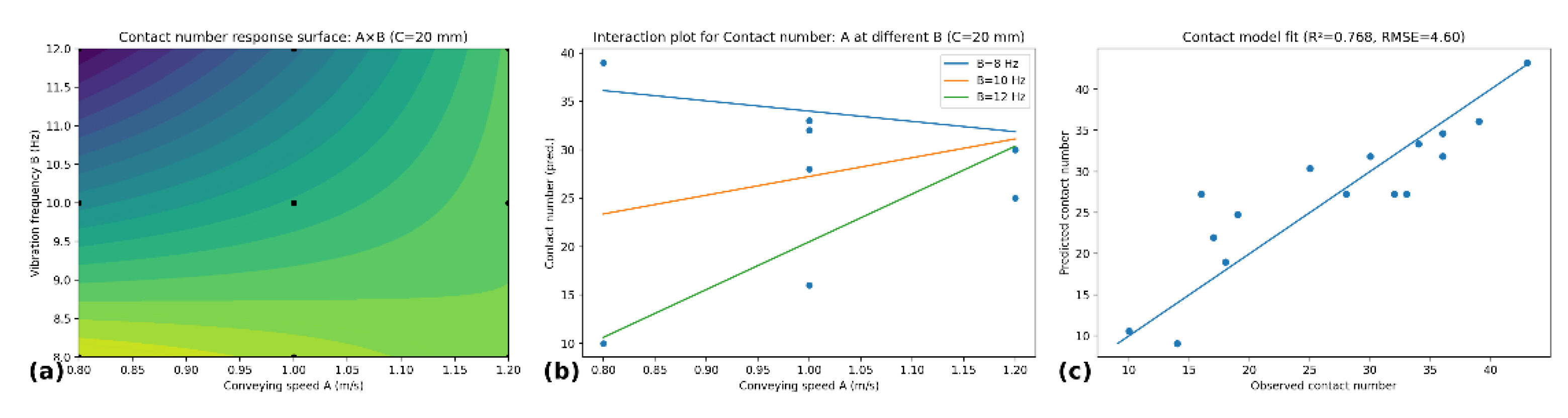
Figure 12.
Interaction effects and model fitting for D80 (80% sediment deposition distance) in the three-factor response surface. (a) Response surface of D80 with respect to transport velocity A and vibration frequency B (amplitude C set at central level); (b) Response surface of D80 with respect to vibration frequency B and amplitude C (transport velocity A set at central level); (c) Comparison of D80 model predictions and measured values. The D80 model is highly significant (p<0.0001), with the main effects of A, B, and C all extremely significant; The interactions A×B (p=0.0134) and B×C (p=0.0071) were substantial, as were the quadratic effects A² (p=0.0022) and B² (p=0.0039). The lack of significant model misfit (p=0.2593) indicates the model is suitable for response surface interpretation and optimization.
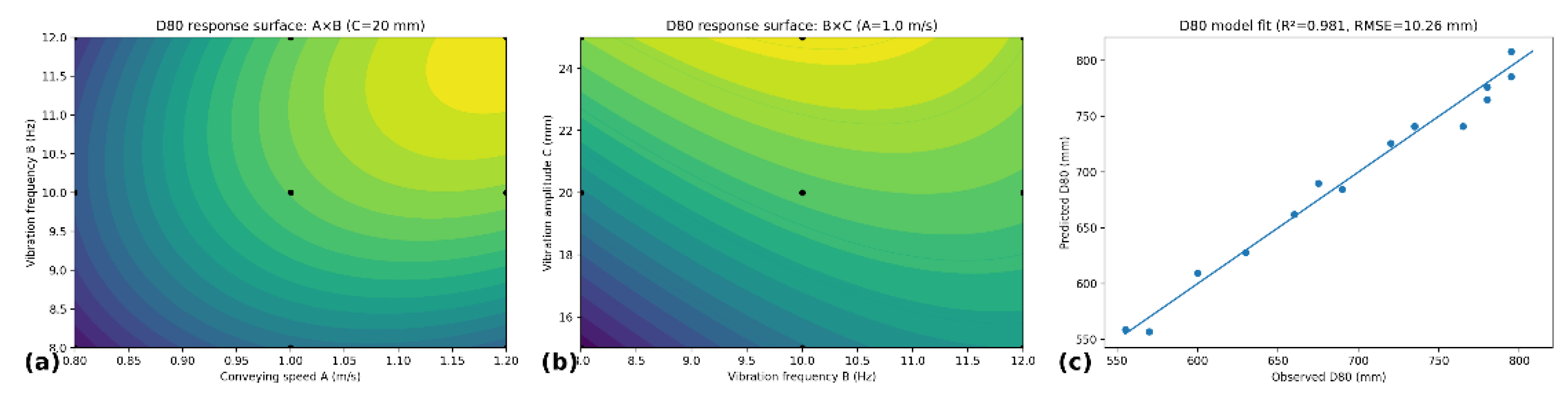
Figure 13.
Field trial validation and operational performance demonstration: (a) Prototype root–soil separation device and soil collection zone schematic; (b) Field operation process and forward direction; (c) Separated Ophiopogon japonicus plant samples (used for soil retention and separation efficiency evaluation).
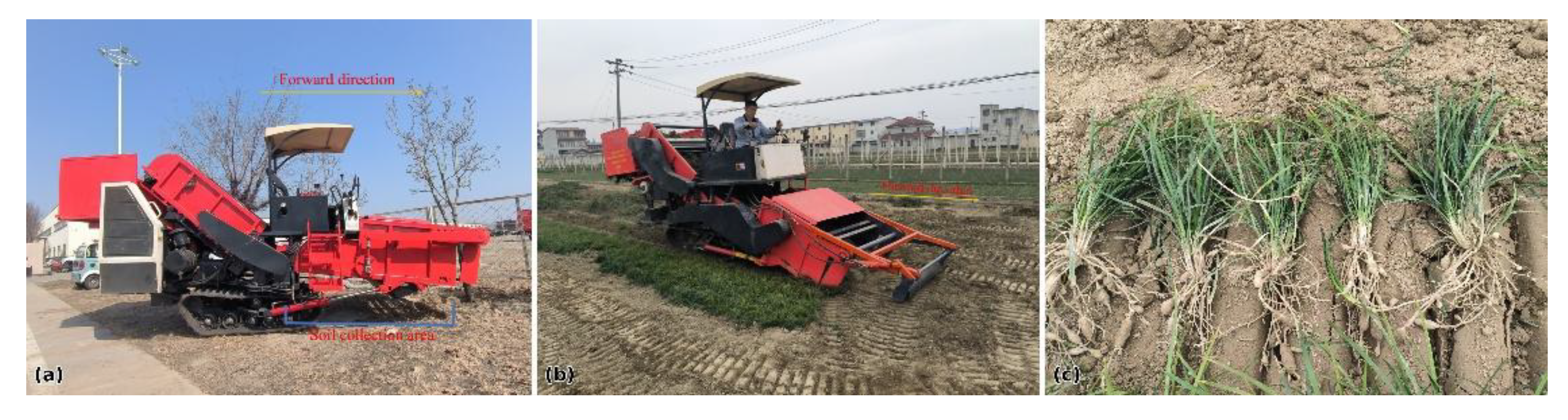
Figure 14.
Comparison of simulated vs. field soil deposition distribution and error analysis: (a) Simulated/field comparison of soil deposition in each collection zone (0–200, 200–400, 400–600, 600–800, 800–1000 mm), overlaid with relative zone error;(b) Comparison of cumulative soil distribution curves with D80 distance annotation (distance corresponding to 80% cumulative soil accumulation); (c) Scatter plot of simulation vs. field measurements for soil mass in each zone (1:1 reference line);(d) Field trial carry-soil mass (carry-soil mass) repeat measurement results and their mean values, used to characterize residual soil levels after separation.
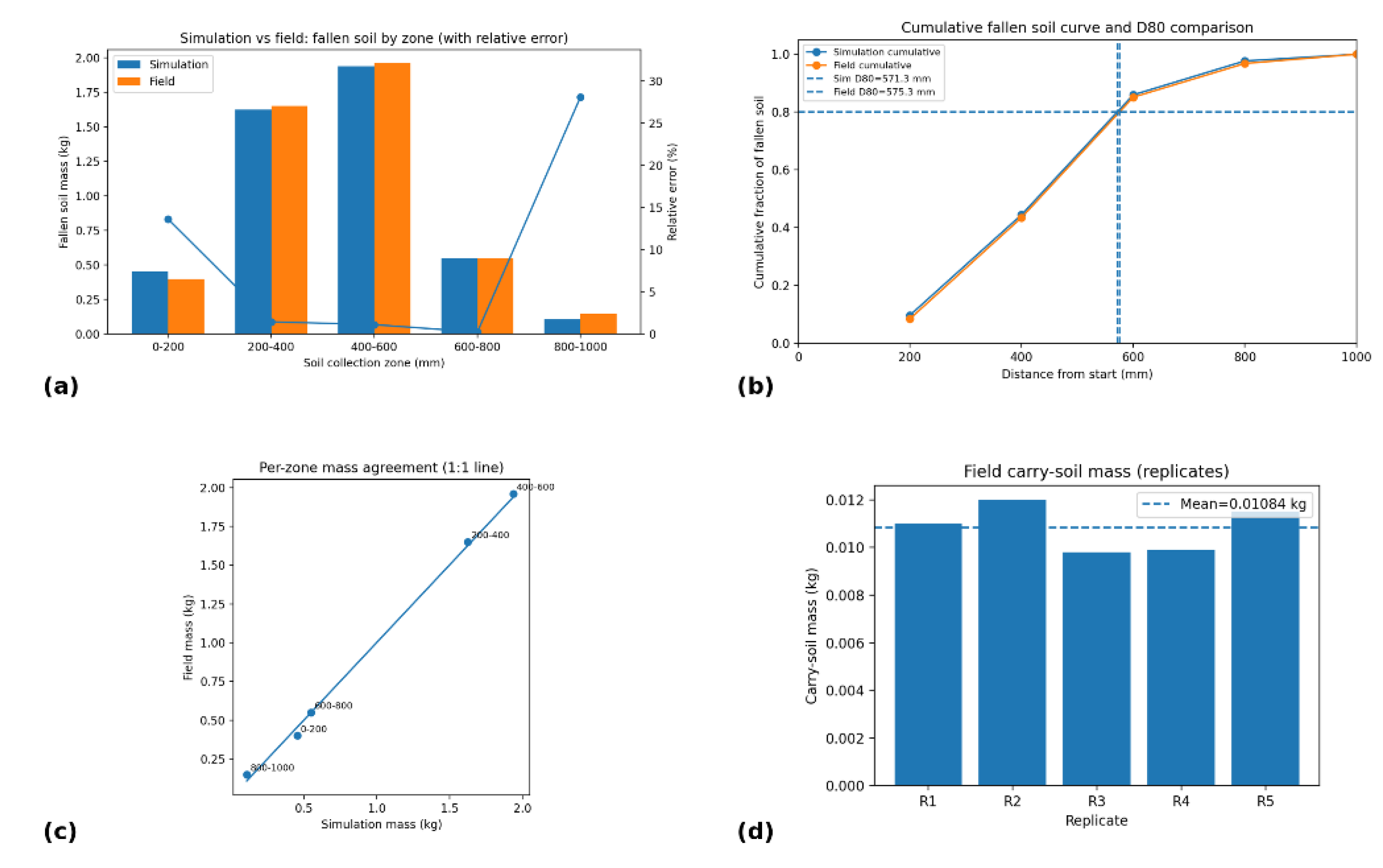
Table 1.
Summary of Material Intrinsic Parameters.
| Parameter | Soil | Plant | chain rod |
|---|---|---|---|
| Poisson’s Ratio | 0.26 | 0.35 | 0.3 |
| Shear modulus/GPa | 0.96 | 0.44 | 79 |
| Density/kg·m⁻³ | 1260 | 1021 | 7865 |
Table 2.
Summary of Material Contact Parameters.
| Parameter | Soil- chain rod | Soil-Plant | Soil-Soil | Plant-chain rod |
|---|---|---|---|---|
| Static Friction Coefficient | 0.30 | 0.30 | 0.30 | 0.30 |
| Rolling friction coefficient | 0.05 | 0.05 | 0.15 | 0.01 |
| Impact recovery coefficient | 0.30 | 0.30 | 0.30 | 0.30 |
Table 3.
Experimental Factors.
| Number. | Conveying speed (m/s) | Vibration frequency (Hz) | Amplitude (mm) |
|---|---|---|---|
| 1 | 0.8 | 8 | 15 |
| 2 | 1.0 | 10 | 20 |
| 3 | 1.2 | 12 | 25 |
Disclaimer/Publisher’s Note: The statements, opinions and data contained in all publications are solely those of the individual author(s) and contributor(s) and not of MDPI and/or the editor(s). MDPI and/or the editor(s) disclaim responsibility for any injury to people or property resulting from any ideas, methods, instructions or products referred to in the content. |
© 2026 by the authors. Licensee MDPI, Basel, Switzerland. This article is an open access article distributed under the terms and conditions of the Creative Commons Attribution (CC BY) license.
Copyright: This open access article is published under a Creative Commons CC BY 4.0 license, which permit the free download, distribution, and reuse, provided that the author and preprint are cited in any reuse.


