
Submitted:
07 January 2026
Posted:
08 January 2026
You are already at the latest version
Abstract
With the increasing demand for clean energy and the uncertainty surrounding the application of renewables, recent years have seen ammonia emerging as a viable way to store and transport hydrogen on a large scale. Its increasing importance in national hydrogen policies, as in the case of Brunei, highlights the need to look into technological readiness and global paths of innovation for this novel fuel. This study analyzes the global development of ammonia-based hydrogen production technologies from a methodological perspective and has shown that 708 granted patents to that were systematically screened, sorted and analyzed. A statistically sound retrieval method and screening process, following the PRISMA guidelines, have been employed to categorize the patents by synthesis processes, types of catalyst, and technological field. The results indicate that electrochemical, plasma-based, photocatalysis, and hybrid systems are becoming common paths as low-temperature alternatives, while thermal catalytic breakdown remains the most popular and well-known path to pursue. A range of reactor engineering, system integration, and catalyst design efforts have been undertaken, particularly in Asia. This indicates a high level of industrial and research interest in advancing ammonia-to-hydrogen technologies. These findings offer a clear overview of current technological maturity and emerging innovation trends, supporting long-term transitions toward cleaner hydrogen pathways.
Keywords:
ammonia decomposition
; hydrogen production
; ammonia cracking
; ammonia dehydrogenation
; patent analysis
; ammonia-hydrogen technology
; ammonia electrolysis
1. Introduction
Rapid population growth is driving economic expansion and expanding the scope of modern civilization. The requirement for energy is increasing as a result. Satisfying this requirement is among the world’s top priorities at the moment because of its long-term effects on the economy and the environment [1,2]. The environmental issues posed by energy sources based on fossil fuels have led to the introduction of renewable energy sources as a solution [3]. The world’s renewable energy output reached its highest point in 2023, with solar PV being the main source. But since the G20 countries depend so much on fossil fuels, the world is still a long way from reaching the 1.5 °C climate goal, even with the promises made at COP28 and the G20/G7 initiatives. To meet the 1.5 °C Scenario, the world’s renewable energy capacity must be more than 11,000 GW by 2030; requiring a lot of investments and quick upgrades. IRENA says that by 2050, 91% of electricity will come from renewable sources (RE) [4]. This means that businesses and transportation will need to switch to RE-generated electricity. However, the transition must also consider the historical significance of fossil fuels in industrial development and energy consumption, anticipated to increase due to population and GDP growth by 2040. Countries will need to plan their transitions differently depending on their own situations.
Hydrogen has become one of the most promising clean energy carriers. It could cut CO₂ emissions by a lot and change the natural gas industry [1]. However, it is still hard to store and move safely. Ammonia (NH₃) has become more popular as a hydrogen carrier because it can stay in liquid form at room temperature under a moderate pressure of about 10 bar, like propane. It also benefits from a well-established global infrastructure, such as pipelines, maritime transport, and pressurized storage. Even so, making ammonia and turning it back into hydrogen both use a lot of energy, and ammonia is toxic and corrosive, which makes handling it even more difficult. Still, quick improvements in technology and strict safety rules are making operations safer, more efficient, and less expensive. Because of this, ammonia is becoming more and more popular as a way to store and move green hydrogen; helping the world moves toward a cleaner and more sustainable energy future [1].
As countries explore cleaner RE pathways, national contexts and situations can vary significantly; with Brunei Darussalam representing a case where current energy circumstances shaping the transition trajectory. For decades, the country’s economy was based on its abundant fossil fuel deposits; however, its heavy reliance on fossil fuels for energy generation makes it a key source of greenhouse gas emissions and, by extension, climate change. More than 60% of country’s gross domestic product comes from its substantial oil and natural gas reserves, with LNG, crude oil, and methanol forming the main exports [5]. Natural gas (79%) and oil (16.4%) make up most of the energy mix, with only a small amount coming from renewable sources (0.003%) [6]. Brunei plans to have a 20% reduction in emissions by 2030, a net-zero impact by 2050, a 45% reduction in energy intensity by 2035, and a 200 MW increase in renewable energy capacity by 2025. For a country which has relied heavily on oil and gas [7], meeting these goals is not easy, despite the country’s involvement in BIMP-EAGA Renewable Energy Certificate (REC) to assist RE market across borders [8]. Renewable energy sources provided just 0.01% of electricity in 2021 with a goal of producing 200 MW by 2025 [9]. Despite the government’s effort in developing renewable energy rules and regulations to encourage investment in clean energy technology [6], the country’s RE potential is constrained by limited biogas, geothermal, hydroelectric, and biomass resources; leaving solar and wind power, both variable renewable energy (VRE) sources, as the primary options [10]. Solar represents the most promising resource, but its high upfront costs, large land requirements, low-capacity factors, and intermittency, indicate that solar alone cannot long-term baseload needs [11]. In this context, hydrogen storage offers a significant role, providing a means to stabilize intermittent solar output, support decentralized energy systems, and enhance reliability [12].
These highlight the importance of identifying reliable, efficient, and scalable hydrogen production pathways that can support energy transition effort, with ammonia decomposition emerging as a promising route due to its relatively mature transport infrastructure and its potential to serve as a hydrogen carrier. Therefore, the aim of this paper is to review and analyze patents related to ammonia decomposition technologies. Studying these developments provides insights that are globally relevant whilst also offering perspectives for countries that are considering hydrogen production from ammonia as part of their energy transitions.
2. Background
2.1. Hydrogen as a Clean Energy Carrier
The high specific energy per mass of hydrogen makes it a popular, environmentally friendly, and safe choice for energy storage [3]. With the shift toward renewable energy sources, their importance has grown in recent years. It outperforms fossil fuels and is better for the environment. It’s also more versatile. Renewable energy sources such as solar, biomass, and wind can be used to produce hydrogen, which is not a renewable resource in and of itself. Because of this, it is a promising energy source for a post-carbon world [13,14,15]. The fact that hydrogen can both store and transmit energy makes it an ideal energy carrier. It produces water as the sole byproduct of combustion when exposed to oxygen, and its gravimetric energy density (120 MJ kg⁻¹) is about three times more than that of kerosene (42.8 MJ kg⁻¹) and gasoline (44 MJ kg⁻¹), the fuels used to power airplanes and cars, respectively.
However, hydrogen can also cause issues of its own. Due to its low volumetric energy density and status as the lightest gas, it is not found in pure form in nature. This necessitates the use of substances that include hydrogen in its composition [2]. Hydrogen is not extremely effective for transporting over large distances and has high storage costs, making its widespread use difficult. The extremely low volumetric density of hydrogen means that compressed gas cylinders are only suitable for use in very short distance deliveries. Long-distance transportation is more challenging. The need for safer, more efficient hydrogen carriers with more capacity for on-site generation has prompted this line of inquiry. As of right now, high-density carriers can be made with ammonia, liquid organic hydrogen carriers (LOHCs), or hydrogen in liquid form. However, the volume loss that occurs when liquid hydrogen is subjected to extremely low temperatures renders it less practical. However, due to their lower total cost, ease of usage, and reduced hydrogen loss, ammonia and LOHCs are superior for long-distance transport [12,16].
2.2. Ammonia as a Hydrogen Carrier
Ammonia has a high hydrogen capacity of 17.6 wt%, and it is a promising chemical hydrogen carrier and a more practical alternative because it is cheap, easy to liquefy (it can be liquefied at low pressure, 8.6 bar at 293 K), and there is already a lot of technology for transporting it. The reaction that breaks down ammonia takes in heat:
Also, because it does not contain carbon, it not only helps lower greenhouse gas emissions but also stops the release of hazardous chemicals like sulfur dioxide and carbon monoxide [16,17]. The Haber-Bosch process makes a lot of ammonia, which is a good way to store hydrogen. Using it doesn’t make CO₂, and its energy density is higher than that of both compressed and liquefied hydrogen. When this is used to move hydrogen gas over long distances at low pressures, its naturally low volumetric density is no longer a problem. Because ammonia is poisonous, it might be hard to move and use. All safety and handling regulations must be strictly adhered to. There can be trace quantities of ammonia in the hydrogen even after hydrolysis. Even so, ammonia does have some redeeming qualities. There is a vast supply of hydrogen in this system, and the global shipping network is quite efficient. This makes it perfect for both production and transportation [12]. Eventually, modern technology has made ammonia a viable, environmentally friendly, and cost-effective means of transporting hydrogen. The storage and utilization of renewable energy sources could be greatly enhanced by this [16].
2.3. Hydrogen Production from Ammonia
2.3.1. Overview of Ammonia Decomposition Mechanisms
The process of ammonia breakdown is rapidly rising in importance along the value chain from renewable energy to hydrogen. Even if there is sufficient capacity to produce ammonia and hydrogen on a worldwide scale, the difficulty lies in the fact that existing decomposition systems are unable to produce high-purity hydrogen on the scale required [17]. It is not necessary to use a catalyst for ammonia to decompose at high temperatures. Dates as far back as 1904 indicate studies on this response. There have been several attempts throughout the years to generate the required activation energy. Some examples of these sources of energy are electric current, microwaves, plasma, solar radiation, and systems that integrate the exothermic reactions of ammonia cracking and propane or butane combustion [18]. There are several typical methods for producing hydrogen from ammonia, including thermal catalytic (thermocatalytic), electrocatalytic, photocatalytic, and plasma-catalytic processes [16,17].
One notable and effective way to make hydrogen from ammonia is using thermal catalysis. Without a catalyst, ammonia breaks down at very high temperatures, usually around 1300 K. Due to this, it is essentially worthless. At temperatures greater than 873 K, thermocatalytic breakdown occurs, regardless of the presence of catalysts. The reason behind this is the high energy required to split ammonia into nitrogen and hydrogen due to the strong N-H bonds. To solve these problems, catalysts have been made to speed up the breakdown of ammonia and make more hydrogen. When ammonia molecules stick to the active sites of a catalyst, they turn into hydrogen gas and nitrogen gas. A catalytic reaction describes this phenomenon. The last step in this process is desorption [17]. While theoretically complete ammonia conversion does take place at 649.85 °C, doing so at higher temperatures results in higher energy costs and shorter equipment life. Producing ammonia is less of a challenge than hydrogen at high temperatures due to thermodynamic equilibrium. Extreme caution is required to keep the reaction temperature below 500 °C. Hydrogen production will rise, costs will fall, and energy consumption will decrease overall. Catalysts typically experience a decrease in temperature-induced hydrogen production. Research in the future should aim to improve the catalyst’s stability, selectivity, and activity at lower temperatures in order to prolong its lifespan. Large corporations will find this technology safer and more affordable with catalysts that produce more hydrogen at lower temperatures [16].
Another viable on-board option is the electrochemical process, which, at relatively low temperatures, can decompose ammonia into nitrogen and hydrogen. Contrasted with water’s electrolysis voltage of 1.23 V, liquid ammonia’s theoretical electrolysis voltage is substantially lower at 0.077 V. The electrical splitting of ammonia produces amide ions and hydrogen molecules at the cathode. Nitrogen molecules are produced by oxidizing amide ions at the anode. The electrolysis reactor has to be constructed as an extremely closed electrolytic cell in accordance with stringent experimental parameters in order to prevent the oxidation and hydration of metal amides. The current efficiency drops to 85% at a high cell voltage of 2 V due to the inevitable reverse reaction in liquid ammonia. The ideal conditions for ammonia electrolysis need a very low cell voltage and a very high current [17].
Electrocatalytic ammonia breakdown works best in water-based electrolytes, but the pH level does have an effect. Acidic liquids slow down the reaction and break the electrodes, making the device useless. For this reason, alkaline electrolytes are gaining ground. They can aid in the repair of acidic system issues and are more stable. Anodes change ammonia into nitrogen, and cathodes do the same for water, making hydrogen gas. Sometimes, the anode oxidizes ammonia while producing oxygen. The method is pickier and takes longer. Using electrolysis on ammonia is relatively inexpensive, but the reactions are time-consuming and not always selective. Researchers are looking into transition metal catalysts and custom nanostructures as better materials for electrodes. The reason behind this is that no electrocatalyst has been proven to be effective enough to be utilized in commercial processes, despite extensive testing [17].
The photocatalytic process is also a good alternative because it can change NHₜ into N₂ and H₂ at room temperature using catalysts that can be used again and light that can be controlled. Photocatalysis that uses sunlight breaks down ammonia when the pH is high. Figure 8 shows that when light hits the photocatalyst that is stronger than its band gap, it makes electrons and holes. Electrons in the conduction band can change O₂ into hydroxyl radicals, and the empty spaces are strong oxidizers. To break down ammonia with photocatalysis, the electrons and holes on a semiconductor must change the adsorbed species on the catalyst surface. This process makes free radicals and other things that aren’t needed. But only a few photocatalysts have been shown to work to break down an aqueous ammonia solution [17].
2.3.2. Role of Catalyst in Ammonia Decomposition
To break down ammonia, it is very important to use catalysts. Some of the most common types are nitrides, carbides, bimetallic complexes, noble metals, and non-noble metals. Ru-based catalysts have the strongest Ru-N bond energy, which makes it easier to add and take away N* from them. This is why they fall apart so easily when it is cold. On the other hand, a lot of people cannot afford to use them because they are so expensive. By mixing Ru with cheap transition metals like Ni or Fe, scientists have been able to make bimetallic catalysts. These systems need to be able to better control how they are built and what they are made of. This will save money without hurting performance. Nickel and other non-noble metals are inexpensive catalysts that could be very useful. After Ru, they are the second most active. Adding metal to catalyst supports and making them work better with the metal can help them work better. Different catalytic systems can break down ammonia in different ways. Ru is used in thermocatalytic, Fe is used in electrocatalytic and photocatalytic pathways, and Fe is used in plasma-catalytic procedures. Catalyst supports also make the whole process more efficient, stable, and spread out. Different catalysts break down NH₄ in different ways, so it is important to know how to make hydrogen production more efficient [16,17].
2.4. Patent Landscape on Ammonia Decomposition to Hydrogen
Given the range of decomposition methods and catalysts related to hydrogen production from ammonia, it is important to understand how these technological developments translate into practical innovations. Patents show industry-driven technological advances, often before they are published in academic journals, and this makes them an essential tool for keeping track of how technology is changing. Most of the time, academic journals only publish the results of research whereas patents cover all the business, technical, and practical aspects of the technology that changes ammonia into hydrogen. This includes learning catalyst preparation, reactor designs, system integration, and approaches for reducing energy consumption. By looking at patents, one can also learn about the current state of different technologies, identify leading countries and companies, and observe common engineering approaches [19]; This is particularly valuable in the field of hydrogen production from ammonia decomposition, where many innovations originate from industrial sectors that do not always disseminate their work through academic literature. Understanding patent trends therefore can also help us understand where technology is going and give us a strategic starting point for potential pathways towards energy transition [20].
According to patent statistics, China is likely responsible for the majority of the rise in the number of patents since 2018; and this may include the current field of interests. Studying patents may point to catalyst innovation, low-temperature decomposition techniques, and hybrid cracking systems, and may also highlight emerging technologies, such as plasma-assisted, electrochemical, and advanced catalyst-supported methods. These help identify technologies that are approaching practical deployment and technologies that are still in infancy. As global interest in hydrogen expands, patents can provide valuable insights into future opportunities in ammonia decomposition technologies [20,21].
3. Methodology
3.1. Patent Review Process
This study used a systematic, evidence-based method to find, confirm, and keep patents that were relevant to the area of technology being studied [22]. There are three parts to the method: i) making a systematic search, ii) checking the statistical recall, and iii) improving the dataset with a custom PRISMA workflow. All of this supported the assumption that the reorganized database was complete, non-redundant, and methodologically suitable for further analyses [23].
3.1.1. Search Construction
To ensure that this project receives the right patents, a structured search query was conducted. The following three groups of keywords were used:
- Process-related language, which means that all of the patents discussed the steps needed to produce hydrogen from ammonia;
- Terms based on applications that limit the results to treatments available in the right context of administration; and
- IPC classification codes helped narrow down the searches even further by limiting them to specific technical areas.
These groups of keywords were combined using simple Boolean logic to ensure that each patent found met all of the required criteria.
Q = (Process) AND (Application) AND (IPC)
This multi-layered structure increased the specificity and relevance of the initial dataset.
3.1.2. Recall Validation
Patent databases are vast and contain a wide range of information; therefore, any search method needs to be regularly checked to ensure that it doesn’t overlook any important patents. To address this issue, a statistical recall-validation method was employed.
- Development sample
An initial list of related patents, m was assembled based on literature searches and expert opinion. Searching construction was developed and refined in this manner, such that the search strings capture all m patents.
- 2.
- Hold-out sample
After refinement, the query was fixed (“frozen”), and a separate set of unseen relevant patents was randomly selected. This hold-out sample, denoted as n, to check the completeness of the search.
- 3.
- Calculation of recall
Recall was defined as:
where R is the validation set of relevant patents and Q is the set of patents retrieved by the final query.
- 4.
- Confidence estimation (Clopper-Pearson Interval)
The Clopper-Pearson exact interval was applied to estimate the confidence interval for true recall based upon the number (r) of patents that were correctly retrieved out of a total amount. Let r denote the number of correctly retrieved patents out of a validation set of size n; with resulting confidence interval providing statistical estimate of the lower bound for true recall.
A one-sided Clopper–Pearson 95% lower bound with 95% confidence interval was considered, with α=0.05 [23]. For this project, based on the validation sample of size z = m + n, where m = 20 and n=20, with r = 20 patents retrieved, the recall 95% confidence interval with α=0.05, is given as p ≥ 0.928. Thus, according to the Clopper–Pearson exact method, the search query has identified at least 92.8% of relevant patents with 95% certainty. Even with conservative validation results, this lower bound reveals the lowest recall possible, ensuring that the query is reliable and broad enough for this study.
3.1.3.. Data Collection
The Lens.org database utilizes a chain of keywords and IPC codes in a structured pattern to identify only relevant patents. Keywords were grouped into three categories: process, method, and IPC code. This way, we aimed not only to include common hydrogen-related terms but also those specific to ammonia conversions. Process keywords identified patents related to hydrogen production in general, while method keywords focused on ammonia decomposition. A curated collection of IPC codes, which are even more accurate since technical classes have been filtered out. All the keywords and codes applied during this process are listed in Table 1.
The IPC codes listed in Table 1 represent the technical domains most relevant to hydrogen production from ammonia, catalyst development, and fuel-cell integration. Several codes (B01J23/02, B01J23/10, and B01J23/46) categorize catalysts based on the active metals they contain. Because they are stable and active, iron, nickel, and platinum-group metals are frequently used in the breakdown of ammonia. B01J35/60, B01J37/02, B01J37/08, and B01J37/30 outline the supplies and techniques needed to create catalysts. These consist of heat-treatment procedures, precipitation techniques, impregnation techniques, and oxide-based supports. These categories encompass patents that focus on enhancing the shape, dispersion, durability, and overall performance of catalysts.
Apart from that, the chemical classes C01C1/00, C01C1/02, and C01C1/04 are general categories covering ammonia chemistry, ammonia synthesis, and ammonia purification. These codes are written into patents that deal with the handling, processing, and purification of ammonia before it decomposes or is turned into electricity. The principal means by which hydrogen is prepared from ammonia comprises catalytic thermal plasma electrochemical C01B3/04 production in which splitting of ammonia into hydrogen and nitrogen occurs
Another technical field in the invention is F02D19/06, which relates to engines running with gaseous fuels like hydrogen obtained by dissociation of ammonia. G01N33/18 is also an art that relates to the electrolytic production of hydrogen, such as ammonia electrolysis, and AOR-type hydrogen generation. H01M8/06 relates to fuel cells using gases containing hydrogen. For instance, ammonia cracking upstream can provide PEM or solid oxide fuel cells with clean hydrogen. This set of IPC codes is assigned to ensure that, when combined, the searched claims effectively cover all relevant technological development for catalysts, ammonia chemistry, hydrogen production pathways system integration.
A thorough screening process based on the PRISMA framework [24,25,26] was used to make sure that only relevant and high-quality patents were included in this study. The search began with a comprehensive review of patents related to ammonia-to-hydrogen conversion using the Lens.org database. After that, duplicates, irrelevant records, and non-technical entries were slowly deleted. This multi-step filtering approach ensured that the final dataset only included patents that directly addressed ammonia breakdown, hydrogen extraction pathways, catalytic systems, and improvements at the reactor level.
Figure 1 shows that the first search on Lens.org found 1,394 patent records. This search used process keywords, ammonia-to-hydrogen terms, and IPC categories. After a first-stage de-duplication process got rid of 460 duplicate entries, such as mirrored national filings and identical family matches, 943 different patents were chosen for preliminary screening. During the methodical filtering stage, the titles, abstracts, claims, and technical descriptions of each patent were examined to ensure they all dealt with the synthesis of hydrogen from ammonia. This step eliminated 65 patents that talked about ammonia uses unrelated to the synthesis, such as making fertilizer, refrigeration cycles, NOx reduction, or general chemical processing.
Before the remaining 869 patents were fully evaluated, a second quality-control check was done to find hidden duplicates, misclassified records, and patents that only vaguely mentioned ammonia without explaining a decomposition, cracking, plasma, catalytic, or electrochemical hydrogen-generation mechanism; removing 161 records to give 708 patents in the final dataset. These patents represent the verified corpus for the next analysis of catalyst types, synthesis techniques, system improvements, inventor activity, and geographic distribution.
3.2. Patent Analysis
This section outlines the classification framework used to organize and analyze the 708 patents related to hydrogen production from ammonia.
The classification methodology used in this study, as illustrated in Figure 2, divides the 708 ammonia-to-hydrogen patents into three main categories: Innovation Types, Catalyst Types, and Synthesis Methods. Every category represents a distinct technological viewpoint, and charting worldwide advancements in ammonia-to-hydrogen research requires an awareness of their importance.
3.2.1.. Synthesis Methods Classification
This category describes the process of producing hydrogen from ammonia. It is crucial because different synthesis routes vary significantly in energy demand, operating temperature, catalyst requirements, and scalability. The process of producing hydrogen from ammonia is described in Table 2.
3.2.2.. Catalyst Types Classification
This category shows what each invention does as a functional catalyst. Catalysts have a big effect on how well ammonia breaks down, the temperature at which the reaction happens, the purity of the hydrogen, and the cost of the system. It is easier to figure out which catalytic methods are the most popular in the world. Table 3 shows the different types of catalysts.
3.2.3.. Innovation Types Classification
This category describes the new ideas behind each patent, which could be making certain applications possible, improving system infrastructure, improving process methods, or coming up with new material solutions. Learning about these one-of-a-kind inventions can help you understand how the industry is changing and which technology paths are best for achieving hydrogen goals. The types of innovations listed in Table 4.
Overall, this study produced a high-quality and highly dependable dataset of 708 patents by combining a systematic PRISMA-style screening methodology, statistically validated recall testing, and a meticulously designed search approach. This multi-layered strategy eliminated duplicates, unnecessary records, and questionable cases, while ensuring that the final dataset included the pertinent ammonia-to-hydrogen innovations. The dataset provides a solid and reliable basis for analyzing global trends in synthesis methodologies, catalyst technologies, system-level advances, and regulatory actions.
4. Results and Discussion
4.1. Bibliography Results
4.1.1. Result of Synthesis Methods in Patents
A study was conducted on 708 patents to explore how ammonia is being transformed into hydrogen. The data presented in Figure 3(a) and 3(b) shows a distinct trend: catalytic cracking is still the leading technique, while only a handful of patents are exploring multi-method or hybrid approaches. Although plasma-assisted and electrochemical methods are emerging, they are still in the early stages of development. These observations point to the areas where innovation is thriving and where new technological advancements could take place.

Table 5.
(a) Classification legend for the different synthesis methods used for examining patents on ammonia decomposition. This table showcases all eight synthesis pathways, along with their unique numerical identifiers, which will be referenced in Figure 3(a), (b) Legend of overlapping-category identifiers, highlighting patents that belong to multiple synthesis method classifications.
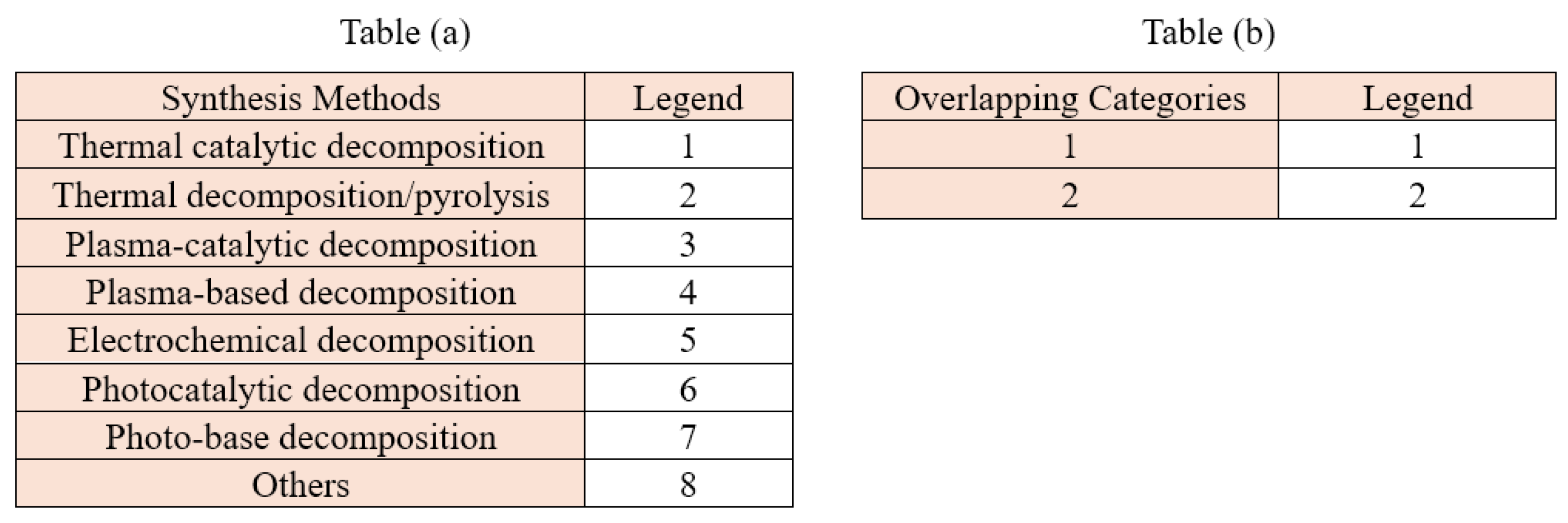 |
Figure 3(a) shows the distribution of patents with respect to the type of synthesis method described, and there is an emphasis on thermal catalytic decomposition, accounting for about 85% of all single-method usage. This large fraction illustrates that ambient and on-topic catalytic cracking is the leading method of making hydrogen from ammonia. In contrast, the more exotic methods, such as thermal decomposition/pyrolysis, plasma-catalytic, and plasma-derived, are all less than 7%, which would indicate their development status is not complete. Electrochemical decomposition is about 5% of the patents, probably driven by a developing interest in using renewable energy for ammonia electrolysis. Photocatalytic and PV methods, on the other hand, amount to 1% below, and these light-driven techniques remain largely at an experimental stage. In general, this distribution demonstrates that catalytic and hybrid routes are now leading research mainstream at all levels, and alternative paths are developed differently.
Figure 3(b) shows that 98% of the patents include just one synthesis method, but 2% involve multiple methods. This limited overlap indicates that, so far, the combination of different hybrid systems, such as catalytic and plasma-based or catalytic and electrochemical, is rather rare. The majority of advances are limited to the enhancement of a single decomposition route, and conventional catalytic cracking is still always taken as the main method. The large number of integrated hybrid patents indicates that integrated multi-method systems are immature and have great promise for the future.
Figure 4 shows how ammonia decomposition synthesis methods are used to make all types of patents. Thermal catalytic decomposition is still the most common method, with 84.18% of classified patents using it. It is commercially viable, has well-known catalyst systems, and has been studied a lot. The other synthesis methods are not as common: thermal decomposition/pyrolysis (2.82%), plasma-catalytic (1.98%), and plasma-based (1.41%). This means that plasma-assisted activation is becoming more popular, but it isn’t very common yet. 5.23% of patents involve electrochemical decomposition, which means that more people want to use electricity to split ammonia into hydrogen, which is a clean energy source. Photocatalytic and photo-based methods are uncommon, making up just over 1% of the total. The Figure 8 also shows that thermal catalytic + electrochemical, plasma-based, plasma-catalytic, and thermal decomposition methods all work together. This is less than 2%, which means that researchers are still looking into hybrid systems. Figure 4 shows that thermal catalytic degradation is the most common type of patent. There are other ways being worked on right now, but they might lead to new technology.
4.1.2. Result of Catalyst Types in Patents
The analysis was also conducted to categorize catalyst-related innovations in the production of ammonia-based hydrogen. Six main catalyst categories were evaluated, and the results reveal several dominant trends and characteristic overlaps across the patent landscape.
Table 6.
(a) Legend descriptions for each catalyst type used in Figure 5(a), (b) Legend descriptions for the percentage distribution of patents across overlapping catalyst categories. For example, Legend 1 represents patents assigned to only one catalyst category (with no overlap), while Legend 2 represents patents containing two catalyst types (with overlapping categories).
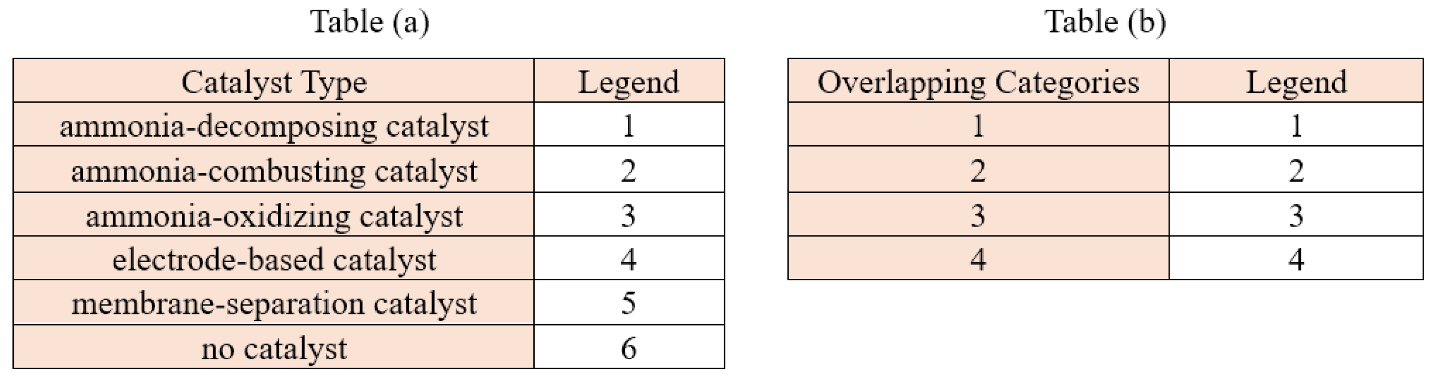 |
Figure 5(a) shows the percentage of patents given to each of the six catalyst groups. The results show that 75% of all patents are for catalysts that break down ammonia. These are also the most common type of catalyst on the market. This indicates that catalyst-assisted thermal breakdown remains the most common approach for researching the conversion of ammonia into hydrogen. The frequency of other types of catalysts is much lower. Ammonia-oxidizing catalysts are next at 5%, while electrode-based and membrane-separation catalysts are next at 6% apiece. Only 3% of all patents are for processes that do not need a catalyst, and only 4% are for catalysts that use ammonia as a fuel. Most patent developments are about technologies that deal with breakdown. Only a few patents deal with oxidation, membrane-assisted, or electrochemical pathways as separate solutions.
Figure 5(b) shows the percentage of patents that have catalyst categories that are similar to each other. About 82% of them are single-category patents, which means they only use one type of catalyst and don’t work with any others. This means that most patented systems use a single, clear catalytic mechanism instead of hybrid systems. Two-category overlaps, on the other hand, make up 13% of the total. These patents cover two catalytic functions, such as breaking down and burning or breaking down and separating membranes. Only 4% of the total is made up of three-category overlaps, and less than 1% (0.56%) is made up of four-category overlaps. These results indicate that hybrid or multifunctional catalyst systems are becoming more prevalent, yet they still represent a minor segment of the overall patent landscape.
Figure 6 shows a more detailed breakdown of how patents are spread across different types of catalysts and their combinations, shown as a percentage of the total dataset. The biggest group is for catalysts that break down ammonia. This group has 76.84% of all patents, which is a lot more than any other group or combination. This shows that the main focus of research and development in the production of hydrogen ammonia is catalytic decomposition. On the other hand, other combinations and single categories only show up a little, each making up less than 1%. This includes Electrode-based + membrane (0.14%), Oxidizing-only (0.14%), Electrode-only (0.42%), Membrane-only (0.71%). Finally, the four-way overlaps (0.28%) and no-catalyst patents (0.43%) are the least common types. This shows that fully integrated, multi-functional systems are still not very common. The bar graph makes it clear that decomposition catalysts are the most important part of the patent landscape. Other catalytic processes only add small amounts to the total.
4.1.3. Result of Innovation Types in Patents
This section presents the results of the innovation-type classification performed on the full patent dataset. By evaluating the patents according to defined innovation categories and identifying both single and multi-category overlaps, the analysis provides insights into the dominant technological directions and the degree of integration present across ammonia-related innovations.
Table 7.
(a) Legend definitions for each innovation-type category used in Figure 7(a), including system-level, process-level, catalyst-level, equipment-level, engineering, application, infrastructure, and other classifications, (b) Legend definitions for the overlapping-category groups used in Figure 7(b), indicating how many innovation-type categories each patent falls into.
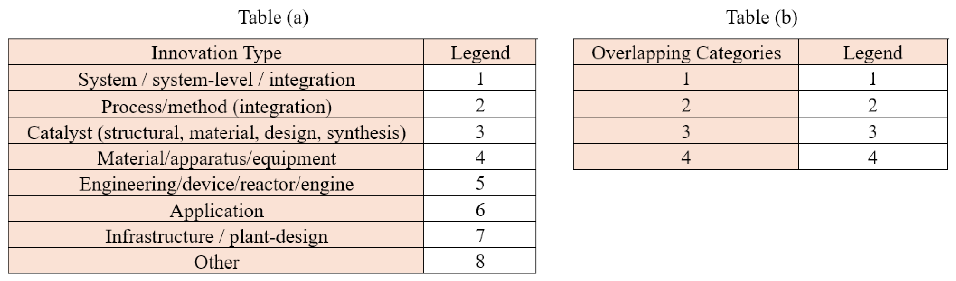 |
Figure 7(a) shows the different types of innovations, with system-level innovations making up the largest share at 36.04%. This shows that there is a strong focus on using ammonia-based technologies in larger system designs. 26.92% of the time, new processes or methods are used to improve reaction pathways and operational strategies. Innovations that focus on catalysts make up 20.48% of the total, showing how important catalytic materials are for making ammonia decomposition work better. The other categories, materials or equipment (6.61%), engineering or reactor design (4.85%), applications (4.18%), and infrastructure (0.92%), do not show up as often, which suggests that these areas do not get as much patenting attention.
Figure 7(b) shows how much the different types of innovation overlap. 39% of patents are for a single type of invention, which shows that many inventions are focused on one area. But the majority—55.5%—combine two types of innovation, which shows that dual-domain integrations like system–process or catalyst–process are common. There are only 5.4% of patents that fall into three categories, and only 0.1% of patents that fall into four categories.
Figure 8 shows a bar graph with both single and combined innovation categories. The most common combination is System + Process, which makes up 28.2% of the total. This shows how closely system design and process optimization are linked in ammonia-related technologies. Other big groups are Catalyst-only (16.7%), System-only (15.4%), and Catalyst + Process (6.6%). These numbers show how important catalysts and system architecture are for breaking down ammonia and making hydrogen. Catalyst + Material (4.7%), System + Application (3.7%), Catalyst + System (2.8%), and Process-only (2.3%) are less common combinations that show up at much lower rates. Most combinations with three or more categories are less than 1%, which shows that new ideas that cross multiple domains are rare. The bar graph shows that most of the new ideas in this field are in one category or simple two-category combinations.
4.1.4. Results of Patents Based on Their Publication Dates
Several time-based variables were used to examine the final validated dataset of 869 patents in order to comprehend global innovation patterns in ammonia-to-hydrogen technology. Analyzing publishing patterns, citation patterns, and inventor participation can reveal insights into the field’s rate of expansion, the technologies attracting the most interest, and the areas where significant advancements are being made. These graphs provide context for the technological maturity of ammonia-cracking processes, particularly thermal-catalytic techniques, and demonstrate worldwide momentum that can inform future research priorities, technology adoption, and hydrogen development strategies.
This graph shows that the number of patents stayed about the same from 2005 to about 2017. The number of patents started to go up in 2018, though. After 2020, patent applications go up a lot, reaching their highest point in 2024–2025. More people around the world are interested in ammonia-to-hydrogen research because of goals to reduce carbon emissions, worries about supply chain security, and a growing understanding of ammonia’s potential as a hydrogen carrier. The quick creation of applications instead of patents shows that new catalysts, system designs, and ideas are still being made at this creative and dynamic time. Also, these patterns show how important it is to look at patents when trying to guess what technology ones may use or add to its future hydrogen projects.
Figure 10 shows how often patent from each year are cited by later patents. This is a strong sign of how much technology has changed. Older patents (2005–2010) have more citations on average, especially among granted patents. This shows that they were important building blocks for later inventions, mostly in thermal-catalytic cracking. After 2018, the number of patents goes up, but the average number of citations goes down. This is because newer patents have had less time to get references. This pattern shows that thermal-catalytic cracking is still the most important part of the field, but new areas like plasma-catalytic or electrochemical decomposition are too new to have a big impact on citations. However, they are important areas for future growth, and ones could look into next-generation systems in these areas.
Figure 9.
Graphs of patent document count based on their publication dates.
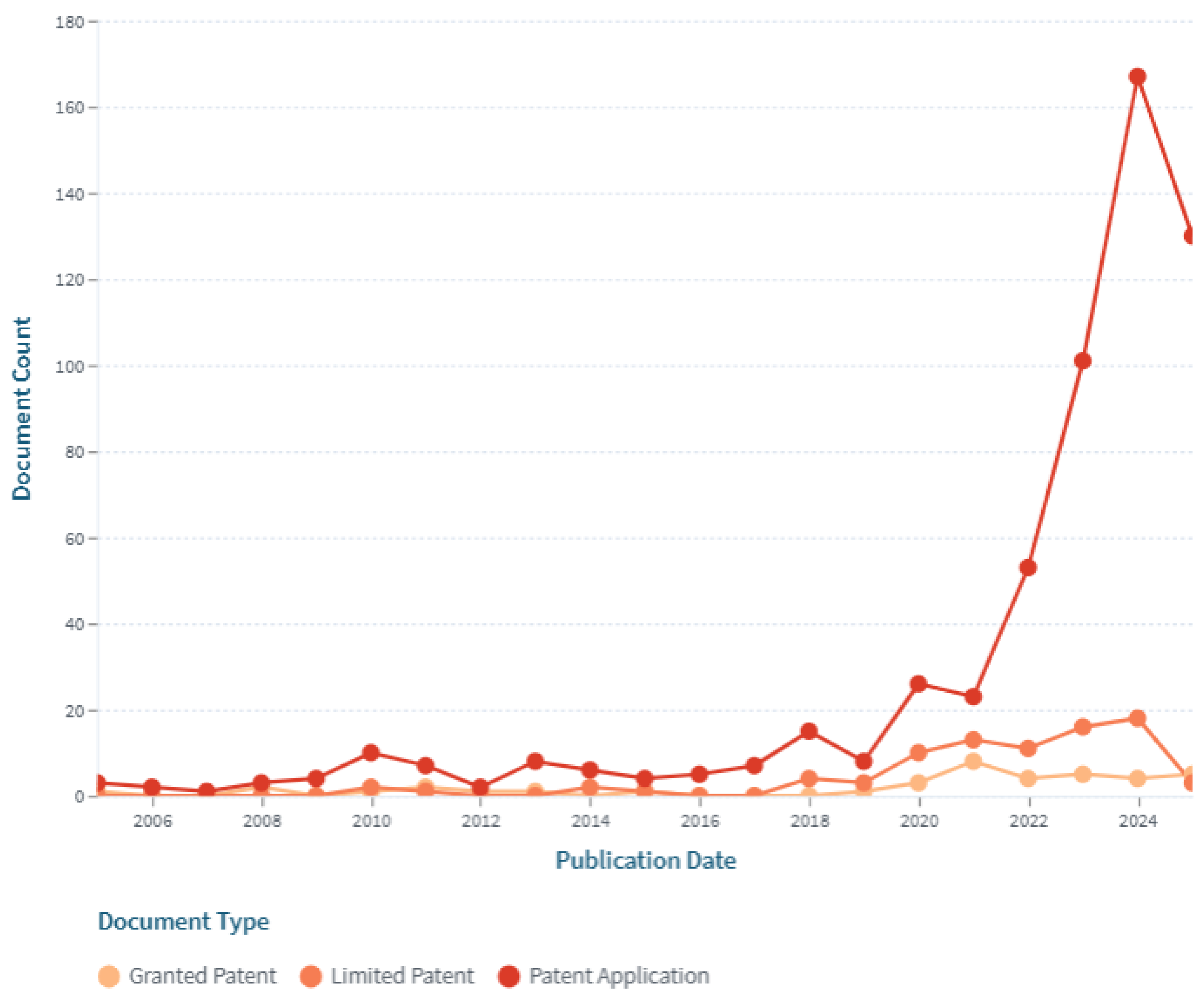
Figure 10.
average forward citation (cited-by patent count) over time by document type.
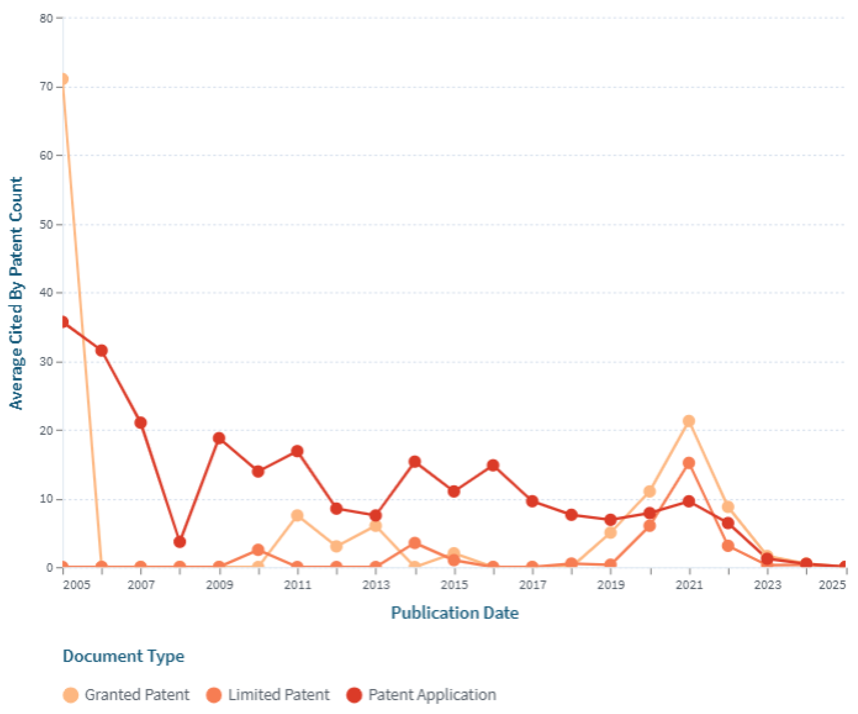
The number of prior patents that each new patent builds upon is shown in this line graph. Backward citation peaks, especially for patent applications between 2011 and 2023, show times when inventors mostly relied on prior knowledge, indicating stages of technological consolidation or improvement. Consistent backward citation levels in subsequent years suggest that inventors are still using well-known thermal-cracking designs (integrated heat-exchange systems, alumina supports, and Ni/Ru catalysts). Therefore, as Figure 11 illustrates, thermal-catalytic cracking continues to be the most developed and well-supported pathway in the innovation ecosystem, offering a solid knowledge base for the deployment of hydrogen in the near future.
Compared to granted or limited patents, patent applications typically involve bigger inventor teams, as seen by Figure 12, which shows the average number of inventors per patent across various document types from 2005 to 2025. This trend intensifies after 2018, when more interdisciplinary cooperation in catalyst design, system engineering, and low-temperature breakdown techniques is prompted by the worldwide push for ammonia-to-hydrogen technologies. Periodic peaks, especially in issued patents between 2012 and 2014, are indicative of significant technological advancements spearheaded by large research teams in countries like the US, China, and Japan. The general upward trend indicates that R&D is becoming more complex, which emphasizes the need for interdisciplinary knowledge in thermal engineering, materials science, plasma-assisted processes, and system integration. This emphasizes how crucial it is to create cooperative research networks both domestically and globally in order to boost hydrogen innovation and assist the creation of ammonia-based hydrogen pathways that are in line with the country’s energy transition objectives.
Table 8 and Figure 13 show a significant shift in worldwide patent activity, with China fast becoming the dominant jurisdiction for ammonia-to-hydrogen innovation. According to the table, China had almost no filings before 2010, followed by a handful in 2010 and 2013. Following 2018, there was a substantial increase in filings, with 26 in 2020, 47 in 2022, 77 in 2023, and a peak of 120 in 2024. The graph’s high ascending curve reflects this. The table and graph show modest but continuous contributions from various countries, including the United States, Japan, the Republic of Korea, and WIPO, showing continued but smaller-scale research work. In contrast, both data sources show that countries such as Australia, Canada, France, and the Netherlands continuously have low and infrequent filing rates throughout time. The table and graph show China’s leading role and secondary innovation clusters in developed economies, giving a clear picture of where technological expertise is concentrated, and which countries could be strategic partners for the adoption or joint development of ammonia-to-hydrogen technology.
4.1.5. Results of Patents Based on Document Count
This section studies patents based on their inventors, applicants, owners, and filing jurisdictions to identify the primary forces driving global innovation in ammonia-to-hydrogen technologies. The structure of the research ecosystem, whether controlled by universities, industrial laboratories, or national research agencies, can be shown by studying who creates these patents and where they come from. This also indicates the countries with the strongest technological commitment to ammonia cracking. These insights, which highlight the people, organizations, and geographical areas that are influencing the field, complement the previous time-based analysis and provide insights on important direction for potential research models, technology sources, and collaboration partners for future hydrogen development.
Figure 14 illustrates how a small number of extremely prolific inventors account for a substantial portion of patent contributions. Luo Yu ranks second with 43 patents, while Jiang Liliang has 47. Other individuals with 15 to 24 patents include Chen Chongxi, Lin Li, and Hong Zhengpeng. The majority of the remaining innovators own between 8 and 12 patents. This pattern indicates the presence of competent research teams, likely at major Chinese research institutes, conducting intensive and long-term studies on hydrogen generation and ammonia cracking. The concentration of creative activity suggests strong specialization and continuity among specialized research groups.
Figure 15 depicts the universities that file the most patents for ammonia-to-hydrogen technology. Univ Fuzhou has the most patents, with forty. Other leading industrial and research organizations are Fuda Zijin Hydrogen Energy Tech (21), China Petroleum & Chemical Corporation (17), and Dalian Institute of Chemical and Physics (15). Many people and organizations file for patents, including universities, state-owned corporations, and national laboratories. Each of these groups files 7 to 14 patents. This distribution suggests that both university research institutions and large corporations, notably in China, are actively engaged in ammonia cracking innovation. The mix of university-led scientific research and industry-led system engineering indicates that the ecosystem has matured. Research institutions or nations may use these trends to guide its efforts to construct a hydrogen research and development (R&D) ecosystem through collaborations between institutions and companies.
Figure 16 demonstrates that a wide range of organizations and institutions own patents, yet most only own 1–3 patents. With 6 patents, Saudi Aramco is in the lead. While Siemens, Hitachi Zosen, BASF, Apollo Energy Systems, and Bloem Energy Corporation have made smaller but no less important contributions, Toyota is the owner of three patents. The fact that numerous businesses own low-count technology shows that they are studying ammonia-to-hydrogen technologies on a modest scale, focusing on specific applications such as catalysts, system components, or integrated hydrogen systems. This variety also indicates that ammonia cracking is a quickly expanding and competitive area, with multiple organizations simultaneously working on creative concepts. The existence of well-known companies worldwide suggests that there may be industrial partners and technology providers there.
Figure 17 shows a highly uneven global distribution of ammonia-to-hydrogen patents, with China leading the field with 423 patents, much more than any other nation. Countries like Australia, Canada, the UK, France, Luxembourg, Bulgaria, and the Netherlands only contribute a small number of patents, whereas the next tier, which includes South Korea (65), the United States (60), WIPO (59), Japan (58), and the European Patent Office (24) shows strong activity among advanced economies. In addition to highlighting China’s supremacy, this trend gives a clear image of the regions with the highest concentration of expertise and the countries that may be crucial partners for technology transfer and collaboration. China’s sharp increase in filings after 2020 is depicted in Figure 13, which also shows the steady growth of other big jurisdictions and the irregular contributions of smaller ones. When taken as a whole, the two charts show a concentrated innovation landscape driven by China.
4.2. Technology Updates
The technology updates from selected patents on hydrogen production from ammonia were organized by synthesis pathway: thermal, thermal-catalytic, plasma-based, plasma-catalytic, electrochemical, and photocatalytic, as well as a set of unique routes (e.g., photo-driven, mechanochemical ammonolysis, and chemical-chain methods). The analysis identifies key inventions, and process advances to illuminate technological progress.
4.2.1. Thermal Catalytic Decomposition
- With ammonia-decomposing catalysts
This method found that 84.1% of the patents chosen are for thermal catalytic decomposition. The oldest patent is from 2005 and the newest is from 2025. The first patent for this method, US6936363B2, was filed in January 2003 and has 70 forward citations and seven references to previous patents. In August 2005, it got its first granted patent. A small hydrogen-generation system makes H₂ by speeding up the breaking up of warmed ammonia (NH₃) from liquid or degassed water storage. At 500 to 750 °C, alumina pellets that have been treated with Ni, Ru, or Pt catalysts are used. An electric heater or a catalytic or lean-gas burner that runs on fuel-cell anode off-gas provides heat. The polymer-electrolyte fuel cells need to be cleaned up after they are used, but alkaline fuel cells can use the hydrogen–nitrogen mix [27].
On the other hand, The US12442324B1 patents, on the other hand, use the ammonia cracker as part of the vehicle’s thermal system for internal combustion engines. A high-surface-area Inconel® 625 heat-exchange catalyst is activated by the heat from the engine’s exhaust. This catalyst can be 3D-printed as a TPMS lattice or tube-bundle core. A secondary electrically heated catalyst downstream makes sure that hydrogen is made when the engine is cold-started or under low load. Electronic control handles temperature, pressure, and expansion. It coordinates plate heat exchangers and valves to send a controlled H₂/N₂ mixture, with optional NH₃ co-feeding, to hydrogen and ammonia fuel rails and injectors without using fossil fuel promoters. The technology makes hydrogen and uses ammonia as a heat-transfer fluid on the cool side. Radiator bypass channels and active grille louvers help with thermal management, making it possible to make the radiator smaller or remove it to improve aerodynamics. This new design is a vehicle-integrated ammonia-to-hydrogen combustion and thermal-management system for spark- and compression-ignition engines. The old design had an externally heated ammonia cracker for fuel-cell applications [28].
JP2005145748A is the second most cited patent (49) and the second earliest patent filed, in November 2003. This patent shows a hydrogen generator for vehicles that use liquid ammonia as a hydrogen carrier for fuel cells. Liquid NH₃ is stored, turned into gas, preheated with heat from the reactor, and broken down over a cheap Ni/Al₂O₃ catalyst at 800–900 °C. The system can provide hydrogen for a 102 kW PEFC while keeping the residual NH₃ in the reformate below ~300 ppm. It has about 10 L of catalyst and a space velocity of ~3000 h⁻¹. A water-based ammonia remover then takes up most of the NH₃ that is left, bringing its concentration down to a few ppm, which is safe for PEFC operation. The design also captures heat, re-evaporates NH₃ that has been absorbed so it can be sent back to the storage tank, and uses the water from the fuel cell product again. Overall, this is a thermally heated, catalytic NH₃ cracker with built-in NH₃ scrubbing and recycling that is designed to provide low-ammonia hydrogen to automotive PEFCs [29].
The patent CN201395510Y was filed in March 2009. It was granted in February 2010. This is the third oldest patent. This patent is for a big hydrogen-rich gas generator that uses catalytic ammonia decomposition in long alloy reaction tubes that are heated by burning natural gas or LPG. This makes the heat flow faster than electric heaters. Adding ammonia to steam makes the reaction go faster and makes cracking work better. The gas mix is about 75% H₂ and 25% N₂, and it flows at rates of more than 1 × 10⁵ Nm³/h and pressures of up to 2.0 MPa. The system has a two-step heat exchange and a loop for washing and soaking up demineralized water to get rid of more NH₃. This keeps the NH₃ level below 1 × 10⁻⁵ v/v and sends ammonia back into the circulation system. The heat that is wasted from the cracking furnace is used to make more steam. This makes the whole system work better when it comes to heat. All of these parts work together to make a good ammonia cracking system that burns the ammonia to heat it up and has good heat integration and purification. This system can always make very pure mixtures of hydrogen and nitrogen gas, which are used to break down industrial catalysts [30].
CN201512408U is the 4th earliest filing, filed in June 2009 and granted in June 2010. They relate to a small ammonia cracking furnace heated by combustion, which may be used for the supply of hydrogen in catalyst reduction on factory scales. Ammonia in liquid form is pumped to an evaporation heat-exchange vessel/vaporized/ and then introduced into a vertical reaction tube containing a nickel catalyst for thermal decomposition of the ammonia. A diesel- or natural-gas-fired burner located at the bottom of the reactor generates elevated temperatures necessary for catalytic NH₃ decomposition (2NH₃ → 3H₂ + N₂). The unit has a double-layered evaporator that extracts heat from cracked gas to preheat incoming ammonia to enhance thermal efficiency. A thermocouple is attached to control the temperature, and a simple outlet tube leads away the hydrogen–nitrogen mixture formed. The system has a small start-up cost and does not require storing hydrogen or supplying it from externally, being safe and low-cost for generating hydrogen in the field. All in all, it is an easily constructed, applied ammonia cracker based on a common Ni catalyst and designed for ruggedness [31].
KR102247199B1 is the third most cited by patent (40) applied for in December 2020. This patent discloses a non-site, modular technology for high-purity hydrogen generation through the traditional thermal catalytic decomposition of ammonia and subsequent PSA purification. The liquid ammonia is pumped, waste-heat-vaporized, and preheated to 300–500 °C prior to being fed into a packed-bed reformer equipped with supported metal catalysts (Ru, Pt, Pd, Rh, Ir, or Ni/Co/Fe/Cu/W/Mo oxides). Ammonia is then decomposed at a temperature of 500–700 °C, producing hydrogen and nitrogen, the product being cooled and fed to TSA or PSA towers containing zeolite or activated charcoal to eliminate any remaining ammonia down to 1 ppm. A succeeding PSA or VPSA stage discharges nitrogen and yields, at 70–90% of the theoretical yield, hydrogen with a purity higher than 99.999%. Extensive heat integration, including reformer exhaust for vaporization and preheating of ammonia, and regeneration of adsorbents, contributes to a low external energy requirement. The system is constructed as compact box-type modules that can be conveniently installed and scaled up for the production of high-purity hydrogen [32].
The most referenced patent (375 references) applied in 2022 is US11795055B1. The present invention is, in general, related to a burner-heated ammonia cracker with an integrated fuel cell for low/medium H2 demand. Liquid or gas NH 3 (<2bar) is then fed to a thermal catalytic cracker (500–750 °C) where it can be cracked to H₂/N₂, which can be directly introduced into an alkaline fuel cell; in case of PEM, just a simple polishing step (Pd membrane/activated carbon) has been considered after the cracker in order to Ds remove NH₃ from the feed. Crucial to the system is an energy cycle; some of the fuel-cell H2 off-gas is combusted in a catalytic/lean-gas burner, and used for endothermic cracking heat generation, enabling fast start-up and low specific weight per kW. Besides the catalysts, two reactor geometries (stackable plate-type cracker and tubular cracker) are suggested by the patents for efficient heat transfer at a 500–650 °C temperature level. The burner position, along with the use of ammonia preheating to stabilize the catalyst bed properly [33].
The 2nd most cited patent (119) applied in September 2020 and granted in February 2025 is US12227414B2. The invention discloses a small, electrically heated reactor for cracking ammonia into hydrogen as needed. Traditional Ru/Fe/Co ammonia-decomposing catalysts are supported on a conductive metallic monolith (e.g., FeCrAl) with a ceramic wash coat (Al₂O₃, ZrO₂, MgAl₂O₃, CaAl₂O₃), and by direct Joule heating can be brought rapidly to ~300–700 °C and optionally up to 1300 °C without the need for a fired furnace. The reactor is characterized by close thermal coupling, a pressure shell with an interspace, an optional design of the bayonet heat recovery, and power-controlled temperature regulation. Through modulation of the electrical input and flow rate, the system can rapidly switch between different operating conditions, providing flexibility to decentralized NH₃-to-H₂ conversion. It forms, in combination with PSA/TSA or membrane purification and fuel cells or gas engines, a flexible, highly effective thermal catalytic cracker as an alternative to the electrochemical unit [34].
WO2007/119262A2 has the broadest territorial coverage in terms of the number of all possible jurisdictions: 13 (Japan, Eurasian Patent Organization, Canada, Mexico, Australia, United States, European Patent Office, South Korea, Italy, China, Brazil, Israel, WIPO. This patent describes a self-contained ammonia-to-hydrogen supply for the alkaline fuel cells. Liquid NH₃ (≈10 bar) is split into three cascaded steps: two electrically heated thermocatalytic reactors (MA alloy body first, CoO/Cr₂O₃ ring stack second, 500–750 °C) carry out the main part of NH₃ decomposition, and a microwave waveguide with hot high-potential alloy wires completes dissociation of remaining NH₃ by EM resonance. The trace amount of NH₃ is then removed by a wet absorption scrubber so that the H₂/N₂ stream is hydrocarbon-free and low on ammonia, which makes it suitable for alkali fuel cell vehicle application [35].
US2025/0121344A1 (filed December 2024) has the most extended families of those with jurisdictions in Saudi Arabia, Eurasia, the United States, Europe, China, and WIPO (45). An electrically (Joule) heated structured catalyst for endothermic reactions such as the NH₃ cracking to H₂ is described by this patent. As heater and carrier, a 3D-printed or extruded conductive monolith is selected; this is coated with an insulating wash coat of ceramic onto which conventional NH₃-decomposition catalysts (Fe, FeCo, Ru/Al₂O₃) are deposited. As heating is internal and very near to the active phase, the reactor can be rapidly started up for uniform operation at 400–700 °C, and then fabricated into a small, high-pressure (2–200 bar) device, thus meeting the decentralized applications of H₂-from-NH₃. And so, instead of a new catalytic material, the innovation is system/reactor integration [36].
US10753276B2 tied for the second highest number of extended families (17*) among its 9 distinct office jurisdictions, CA, KR, US, AU, GB, JP, INPCOSG, and WIPO. The system of a gas turbine based on a UJSP generally includes a power generator driven by such a turbine. The structure comprises a first ammonia-cracking chamber and a second ammonia-cracking chamber filled with noble-metal catalysts [e.g., Ru, Rh, Pt, Pd], where the ammonia is thermally decomposed into hydrogen-rich gas. This internal hydrogen source stabilizes and intensifies the burning of ammonia in two stages of a combustion chamber. The first chamber carries out primary combustion and turbine driving, and the second operates at a higher equivalence ratio to form NH₂⁻ species for the NOx reaction to minimize emissions. The turbine exhaust heat rejected, which would otherwise be wasted, is carried through the cracker chambers (16) to keep the catalyst at a high temperature without any other outside heat source, and may also be employed as process steam in an independent expander (37) to produce additional power. Thus, the invention is a highly-efficient ammonia-fired power system with integrated capabilities that utilizes catalytic ammonia-cracking for clean combustion and NOx reduction, as well as for maximizing heat recovery [37].
CA2883503A1, filed August 2013, which is the third highest number of extended families (15) and family jurisdiction of 7: Europe/Korea/US/CN/JP/WIPO/CA. A high-performance ammonia-decomposition catalyst employing dormerite type support (C12A7), whether hostile electrons or a hydrogen negative ions system, is provided by this invention. Reactive transition metals, including Ru, Ni, and Co, are highly dispersed over this support and can perform the NH₃ conversion more effectively at temperatures of ~350–600 °C (at higher space velocity) than typical Ru/Al₂O₃ or Ru/CaO. Electrons or hydride species are accommodated in the mayenite cages that, when occupying its active site, can modulate the behaviour of the active metal and facilitate ammonia decomposition to achieve effective CO/CO₂-free H₂ + N₂ production across a broad range of NH₃ concentrations. As the support is abundant, nontoxic Ca–Al–O oxide, the catalyst possesses high activity with approaching lower cost and better resource efficiency for NH 3 hydrogen production [38].
CN120155131A is a 2nd recent invention and was applied by the University of Shanghai Jiaotong in Mar. 2025. A type of small-sized, high-efficiency self-heating ammonia decomposition reactor, which combines burning, heat recovery, and catalysis cracking system by a three-level nested structure, is disclosed. As an internal heat source, ammonia-hydrogen co-combustion is employed, with which the problem of ammonia’s poor ignitability is resolved, and the requirement for external furnaces is removed. Hot exhaust gases from the reaction zone are recirculated around the reaction layer, allowing heat to be used more efficiently and maintaining a high reactor temperature, which results in energy savings. Ammonia is fed into the catalytic reaction layer (Q) (catalytic filled with); a Ru-based granular catalyst that can be converted, at 450° C, by more than 99%, and travels upward through spiral flaps that enhance mixing (mixing), residence time (residence period of time), and decomposition completeness (decomposition entirety). With a hydrogen productivity of 50 Nm³·(m³·h)⁻¹, the reactor design may find application for mobile or decentralized ammonia-to-hydrogen processes like onboard marine engines and refueling stations. In general, the present patent discloses a system-level innovation of autothermal ammonia cracking, showing relatively more compactness and improved combustion stability with a high heat recovery focus rather than a novel catalyst material [39].
At the same time as the application of CN120155131A by the same applicants, patent CN119951503A discloses a low-Ru, low-temperature, and high-activity Ru-based catalyst for thermal catalytic ammonia decomposition to hydrogen based on a core-shell Ru/CeOx@N-doped porous carbon structure. A Ce-based metal-organic framework (Ce-BTC) is initially prepared via a hydrothermal method from Ce(NO₃)₃·6H₂O, H₃BTC, and PVP in the mixed solvent of ethanol/DMF and further transformed by argon calcination into a CeOx@porous carbon composite with a large surface area and adjustable porosity. The Ru precursors (Ru₃(CO)₁₂, Ru(NO)(NO₃)₃, Ru(acac) 3 or RuCl₃) are first deposited by impregnation (3 wt % Ru compared to the calcined support), and then heat-treated under Ar (300 °C then 550 °C); highly dispersed sub-nanometric sized of active nanoparticulates are obtained, which are confined in a carved cavern CeOx@N-doped porous carbon. The catalyst particles that are obtained (40–60 mesh) are then screened for the NH₃ decomposition in a quartz-tube, fixed-bed flow reactor under NH₃ flow (GHSV ≈ 2000 mL·h⁻¹·g_cat⁻¹). Detailed studies reveal that Ru₃(CO)₁₂/CeOx@PCN exhibits the highest activity and selectivity, with approximately 80–88% of NH₃ conversion at 350 °C and >98% of NH₃ conversion recorded after reaction at 400 °C, benefiting from improved intrinsic activity, outperforming both conventional Ru/oxide or Ru/carbon catalysts in terms of stability and reducing Ru consumption. The improved reaction rate is proposed to stem from the synergistic interaction between CeOx (containing oxygen vacancies and variable valence state Ce³⁺/Ce⁴⁺), N-doped porous carbon shell, and Ru electronic structure modifications, therefore suggesting a promising MOF-derived, low-Ru-content catalyst strategy for NH3-based efficient LT H2 production [40].
CN120268340A is the most recent invention applied for in June 2025, by Hebei Academy of Sciences, Institute of Energy, and Shijiazhuang Tiedao University. This patent relates to an integrated ammonia-cracking hydrogen generation apparatus in which the cryogenic energy of liquid ammonia is effectively utilized to improve the overall process heat efficiency. Ammonia vaporization, catalytic cracking, hydrogen purification, compression, and storage, scaled down to refueling, are integrated into one single unit. Ammonia is then decomposed into hydrogen and nitrogen by thermal dissociation, and the gas is purified and compressed in a multistage process with recovered cold integrated as an intercooler to go through a near-isothermal compression process with lower power demands. This system, charged by the off-peak electricity, can store hydrogen and cold energy, which would be utilized for a BF-natural gas mixture during refueling in higher temperatures of daytime. It enhanced performance efficiency, safety, stability, and economic feasibility at the same time. On the whole, it is a system-level innovation that focuses on multistage energy recycling and integrated operation rather than catalyst development [41].
CN223127277U was submitted in Sep 2024, and the 3rd most recent patent (July 2025). It reveals a type of integrated coupled dual-source hydrogen production system by combining alkaline water electrolysis with ammonia catalytic decomposition. Alkaline electrolyte from electrolysis is recycled in an ammonia distillation column, where it decomposes readily, volatilizing ammonia over Ni or Ru catalysts to form H2 and N2. Hydrogen coming from both electrolysis and decomposition is purified (adsorption) and mixed in order to be utilized downstream. The system is hybrid at the level of system/integration and not at the conventional catalytic cracking (like ammonia decomposition in a usual reactor), since it combines electrochemical with thermal catalytic hydrogen production [42].
GB2633197A is the second latest granted patent (Oct 2025). An additional system-level innovation in industrial ammonia cracking is also offered for patenting, where two reactors are employed- a primary furnace-heated catalytic cracker and a secondary, smaller ammonia cracker. The secondary reactor makes a hydrogen-rich cracked gas, which can be used to: (1) reduce oxide catalyst in the reformer during start-up; (2) provide a hydrocarbon rich fuel stream for lighting the burners if ammonia alone will not sustain flame formation; (3) suppress nitriding by having a lower partial pressure of ammonia entering and remaining on surfaces in the reformer tubes; and/or during continual operation. The primary reactor uses standard Ni- or Ru-based NH3 decomposing catalysts, in furnace-heated tubes such as those used for steam reforming. The secondary reactor may be adiabatic, electric, or gas-fired, allowing separated synthesis of cracked gas when the main plant is operating below full scale. Other possible attributes are PSA hydrogen purification, tail add gas recycle as fuel, and double feed (fresh vs pre-cracked ammonia). In conclusion, the system has the reduced risk of operation at start-up, the ability to more effectively activate the catalyst, an extended operating range, and enhanced process efficiency for large-scale production of hydrogen from ammonia [43].
The latest patent is CN117509537A (October 2025). The present invention relates to a method for dissociating NH₃ at low temperatures by the use of electric energy. This is an improvement over conventional thermal catalytic cracking, which occurs only during temperatures above 400 degrees Celsius. (1) Synthesizing the Ni/Co/Fe–CeₓZr₁₋ₓO₂catalyst through solution combustion and activating its low temperature performance using an indirect electric field can convert a considerable amount of NH3 at temperatures less than 250-300 °C without requiring external heat sources. When the new process described here uses very stable electric fields, a little nano-SiC (a few %) is used as an assistant material. When an electric field is applied at 250 °C, some of the catalysts convert with a rate of 50–60%, which contrasts markedly with thermal-only conversion efficiencies (less than 10%). Based on the design, the ammonia cracking could be substantially enhanced by the electric field, even at low pressures. The little bit that it might be useful is if one has a small hydrogen plant of 3-10 Nm/h, which should be expanded in the future when heating with natural heating no longer works (i.e., too hard to reach the temperature)[44].
- With ammonia-oxidizing catalysts
The first and only patent is CN120325293A, which was filed in March 2025. This report presents a novel series of Pd–transition-metal core–shell nanocatalysts (Pd@M, where M = Co, Fe, Cu, Zn, Ni, Cr, and Mn) that facilitate low-temperature continuous hydrogen production through the oxidative dehydrogenation of ammonia. Microwave-assisted microemulsion–gas-induced synthesis is used, and Pd as the core is strengthened by a uniform transition-metal shell that makes it more stable, better at transferring hydrogen, and less likely to oxidize. When reduced, catalysts are very active between 75 and 300 °C (the actual bed temperature is 90 and 350 °C), with Pd₀.₇Co₀.₃ at ~90 °C beating those of Pd-only or single-metal controls. The core-shell structure makes it possible to convert NH₃ at low temperatures, well below the standard ≥400 °C thermolysis. This is a step forward for the O₂-promoted route of NH₃ decomposition. Ammonia will be a promising way to make hydrogen on a large scale at low temperatures because it only uses cheap commercial precursors and is easy to make [45].
- With ammonia-decomposed and ammonia-combusting catalysts
The earliest invention, most cited patent (107), and highest number of extended families (19) is US7875089B2, which was filed in 2004. Its nine family jurisdictions cover the US, Japan, Europe, Korea, Australia, China, Mexico, and WIPO. This patent describes a small, portable NH₃→H₂ generator for small fuel cells. It uses thermal catalytic ammonia cracking in a micro-channel/finned reactor that runs at a moderate temperature (about 550–650 °C). This means it can be made of stainless steel or titanium and doesn’t need high-temperature alloys. A small burner (butane) makes most of the heat, but there are also options for electric or autothermal NH₃ heating. The unit adds a small, acid-impregnated carbon adsorber that is cooled by the incoming liquid NH₃. This is because lower-temperature cracking lets some NH₃ slip through. As a result, the outlet H₂/N₂ is fuel-cell grade (<1 ppm NH₃). Ammonia-decomposing catalysts (Ru/Al₂O₃ or Ni) are used, and the new idea is to combine systems and reactors to make portable fuel cell power [46].
The most cited by patent (58) is WO2011/107279A1, which was filed in March 2011. A small, heat-integrated ammonia cracking system that uses solid ammonia storage (metal ammine salts) to make hydrogen for fuel cells that work at low temperatures. The solid cartridge gives off ammonia, which is then broken down by heat in a “jacket-cracker” reactor. The inner chamber (Pt/Al₂O₃) burns NH₃ or recycled H₂ to make heat, and the outer chamber (Ru/Al₂O₃) breaks down NH₃ into H₂ and N₂. A heat-recovery jacket warms up the ammonia feed and sends extra heat back to the storage module. This makes the system work better. PEM fuel cells need an NH₃ absorber to clean up the gas stream, and dual-cartridge reactor modules let them run all the time. The new technology is not about new catalyst materials; it’s about combining reactors and controlling heat. This makes it possible to safely and efficiently get hydrogen from solid ammonia [47].
CN111957270A, which was filed in September 2020, is the second most cited by patent (47). This patent describes a whole system for making hydrogen by breaking down ammonia. It is supposed to be used at hydrogen refueling stations. The system uses old-fashioned catalysts made of Ni, Fe, or Ru to break down ammonia by heat. This makes a mixture of hydrogen and nitrogen that is cleaned up in three steps: ammonia adsorption, pressure-swing adsorption (PSA), and membrane separation. One of the most important new features is that it can run on its own. A catalytic combustion unit uses some of the product gas to make all the heat needed for ammonia cracking. It doesn’t need any outside fuel. The patent also makes the process use less energy by using a two-stage heat exchange process in which hot combustion exhaust heats up the ammonia feed that is coming in and regenerates the ammonia adsorption bed. The hydrogen that has been cleaned is stored in tanks that can handle both low and high pressures. This lets you fill up with hydrogen at pressures between 350 and 700 bar. Most of the patent is about integrating systems at the system level. It uses regular catalysts to make hydrogen production more efficient, improve heat recovery, and make it easier to use at refueling stations. This makes it a good design guide for making hydrogen in a decentralized way using ammonia [48].
The most recent invention to be filed is CN119015872A. There is a small ammonia-to-hydrogen system that uses catalytic combustion heating to break down ammonia. It has a dual-zone catalytic burner (Pd/Pt for ignition, Cu/Ni for sustained combustion), a heat exchanger, and a Fe-based ammonia-cracking reactor. After startup, the system heats itself and doesn’t need any fuel because some of the hydrogen it makes is used as burner fuel. The countercurrent heat exchange makes the system more thermally efficient, and the waste heat recovery warms up the ammonia that is coming in. It runs at about 550 °C and converts about 99% of ammonia. Its lightweight, efficient, and easy-to-monitor design makes it good for hydrogen generation on-site or on the go [49].
- With ammonia-decomposed and ammonia-oxidizing catalysts
JP2010180098A was the first patent filed in February 2009 and has been cited the most (5). This patent describes a hybrid autothermal ammonia-to-hydrogen generator that uses carbon nanotubes to combine partial oxidation and catalytic decomposition. The CNTs have different areas for Pt oxidation and Ru/Rh/Ni/Fe decomposition catalysts, which makes it possible for H₂ to be produced without any external assistance. The design eliminates the need for external heating and enhances system efficiency by utilizing nanoscale thermal conduction. This example of autothermal thermal catalytic ammonia decomposition using bifunctional nanostructured catalysts is meant for use in automotive fuel cells or ammonia engines [50].
In November 2009, WO2010/058807A1 was filed. It has the most extended families (10), with family jurisdictions in Japan, China, Europe, the United States, and WIPO. It has the most forward citations (15). This patent suggests an ammonia engine system where a Pt-based ammonia-oxidizing unit is put between the engine and the ammonia cracker to raise the exhaust temperature when the engine is running at a low load. The exhaust gets hotter and then goes into a plate-type ammonia cracker (Ru/Rh/Ni/Fe) that breaks down NH₃ into H₂ and N₂. This means that hydrogen is always available, even when the engine exhaust is too cold. This is a system-level, hybrid thermal-catalytic NH₃-to-H₂ architecture for an ammonia engine. It uses exhaust to heat the engine, oxidation to help it, and optional electric heaters to help it [51].
KR20240010242A is the most recent application filed in July 2022 by Hydrochem Inc. The present invention provides a process for the production of high-purity hydrogen from ammonia employing dual-step selective oxidation. Ammonia is initially thermocatalytically decomposed (500–650 °C) over Ru, Co, Ni or Mo containing catalysts. Residual NH₃ in the product stream is next a) selectively oxidized at 300–650 °C over an Fe- or Cu–zeolite catalyst to form N2 + H₂O (≫95% selectivity, while NOx production <150 ppm). Stable full-scale NH₃ removal is cost-effectively achieved in concurrent operation with controlled O₂ injection and without power-consuming adsorbers while supply of NH₃ (1–3× stoichiometry) was required. The sequence may include a TSA/PSA clean-up for ultra-pure hydrogen (<1ppb NH₃). In contrast to typical adsorption–desorption cycling, this strategy can minimize energy loss and may therefore offer an alternative way to achieve efficient low-emissions ammonia-based hydrogen production and purification [52].
- With ammonia-decomposed and electrode-based catalysts
JP2011204418A is filed in March 2010. This invention is about SOFCs that run on ammonia but have a problem starting up: when they shut down, the Ni/ceria/zirconia anode oxidizes and can’t break down NH₃, so NH₃/NOₓ could get out. The patent adds a step before the main process where a hot, H2-rich reformate is sent to the anode to (1) heat it up to the right temperature and (2) reduce it back to its metallic, NH3-decomposing state. The anode exhaust is burned at the same time, and the hot gas is sent to the air side. This keeps the anode and cathode from getting too hot and causing thermal stress. After that, the system switches to ammonia and recycles anode exhaust to get rid of any leftover NH₃. This keeps NH₃ in the vent at ≤ 5 ppm and makes the stack last longer [53].
The most recent one is CN120332944A in March 2025. A STE-H2 refueling station of an ammonia-decomposition-integrated type (solar hydrogen pilot system) and high-temperature SOEC water electrolysis are detailed. Through solar panels, a steam turbine and molten salt storage system, the SOEC can be fed from with high quality heat and power. The hot SOEC/anode/burner gases are then passed through a reactor, in which the heating-gas line is thermally connected to a catalytic NH₃-decomposition line including an ammonia-decomposition catalyst. The cracked gas is cooled, passed through one to two adsorptions stages for the removal of any unconverted NH₃ and N₂, followed by compressing, cooling and dispensing. The overall energy-use efficiency of the system is enhanced, and the capability to refuel even when the sun is not shining is maintained by allowing solar heat BN exhaust, SOEC waste heat, and NH₃ cracking to share a single temperature ladder [54].
- With ammonia-decomposed and membrane-separation catalysts
WO2008/002593A2 is the first filed invention in 2007, with the highest number of extended families (10). For this family, jurisdiction was found in between the European Patent Office (EPO), Japan, Canada, Australia, the United States of America (USA), China, and WIPO. Disclosed is a system of a hydrogen fueling station constructed to produce hydrogen at point-of-use by autothermal catalytic cracking of ammonia using Ni-, Ru- or Pt-based catalysts between 500 and 800 °C wherein liquid NH₃ is stored, vapourized and decomposed in the presence of the catalyst, undissociated NH₃ being removed by cryogenic, adsorptive or membrane separation, filtered through appropriate filters so as not to clog said storage tank outlet valve and sent back to said storage tank for later use. The clean hydrogen is compressed and provided for use as a vehicle fuel. The novelty of this work is combining ammonia storage, catalytic cracking, purification, and compression at a fueling station to produce clean auto-produced H2, so as to act in a more safety-decentralized way (and reduce the demand for transported hydrogen) [55].
The most cited patent (5) is US10906804B2, filed in 2018 and assigned to the Gas Technology Institute and the University of South Carolina. This ARPA-E–funded patent features a membrane-integrated ammonia cracker that combines a Ru-based NH₃ decomposition catalyst, an H₂-selective ceramic hollow fiber membrane for continuous removal of the H₂ product to achieve >99% conversion at T = 350−450 °C and P =10–15 bar, and in-situ catalytic burner using H₂ as fuel to provide heat for endothermic process. The small reactor supplies PEM-grade, high-purity H₂ (30bar) at ≈88% efficiency and $4 kg⁻¹ cost, representing a thermal catalytic, membrane-assisted breakthrough at the systems level for distributed H₂ generation [56].
US2020/0269208A1, filed 2020, has the highest citation by patent (23). The invention also provides a low-temperature catalytic membrane reactor for the simultaneous decomposition of ammonia and purification of hydrogen streams. The reactor consists of a porous yttria-stabilized zirconia (YSZ) tube with a Ru catalyst loaded on its exterior mesoporous layer, and selective H2 permeation through a thin Pd membrane. In this study, internal surface cesium doping improves the N–N desorption that facilitates effective NH₃ cracking at ~ 400 °C and 1–5 bar flow rates without a sweep gas. It permits the full conversion of NH₃ (10× less catalyst use) and >30 mol m⁻³ s⁻¹ H₂ productivities with superior H₂ purity for PEM fuel cells. It is an exemplar of a novel thermal catalytic, membrane-assisted concept for ammonia-derived H2 production with compactness and high efficiency [57].
CN113604813A is the most recent patent to be filed in August 2021 and has been cited by 17 patents. It discloses an integrated NH₃-to-H₂ compact system, including NH₃ vaporization, high-temperature electric/combustion-assisted decomposition, and a low-temperature gases purifying function in a single vessel. Liquid ammonia is gasified and decomposed at >800 °C by the Ni–Cr electric heater, and then a H₂-combustion tube with a catalyst helps to provide additional heat. The resultant mixed gases are then conducted through a Z-shaped Pd/molecular-sieve separator, cooled by a closed hot–cold circulation loop as depicted in Figure 53, and released into high-purity hydrogen and nitrogen tanks. The patent is related to thermal design as well as the integration of the purification efficiency, and is not focused on a new NH3 - cracking catalyst [58].
- With ammonia-decomposed, ammonia-combusted, and ammonia-oxidizing catalysts
That most-cited-by-patent (52) was invented by Goetsch, Duane A., and Schmit, Steve J. in 2004. US2005/0037244A1 describes an autothermal process for cracking ammonia, where a small amount of the product hydrogen is burned - sometimes with a little fuel and/or ammonia - within or adjacent to the reactor to provide endothermic heat. This avoids the necessity for external furnaces, and small, short-contact-time units (GHSV ≈3 × 10⁴–10⁶ h⁻¹) are able to operate in the range of 700–1000 °C. The patent presents three heat-integrated schemes: a mono-chamber configuration with radiative shields, a dual-compartment unit that heats up an inner cracker through a wall-containing outer combustor, and a coaxial two-pass reactor that warms up the feed by hot effluent. Catalysts Ru, Ni, Fe, and Pt on ceramic or FeCrAl monoliths with the oxide phase stabilized γ-Al₂O₃ produce a contaminated with CO-free H₂/N₂/H₂O stream for use in fuel cells using air as the oxidant and optionally recycling hydrogen [59].
EP4417572A1 optimizes US2005/0037244A1 by dualizing between a single Ru-based bed half-catalytic combustion and NH3 decomposition at a time, with oxygen being fed through multi-perforated in-bed distributors so that a uniform temperature is maintained throughout and the bed is operated at less than 600-800 °C (most preferably about 600-700 °C). The controlled co-feeding of canned water (0.2–1.2 kg H 2 O per kg NH 3 ) can act as a heat sink and enable operation up to 20–40 bar without equilibrium penalties. Downstream, PSA produces pressurized H₂, and an adiabatic catalytic boiler oxidizes the PSA offgas to create fuel vaporization and preheat the NH₃/H₂O feed with heat recovery. Overall, the new design delivers a small volume low-NOₓ pressurized H₂ plant with reduced O2 consumption and increased H2 yield when compared to flame-assisted Ni-based systems [60].
US2012/0015802A1, filed in 2010, has the most extended families (23) with jurisdictions in the US, Korea, Europe, China, and WIPO, and the highest cited patent (8). An autothermal ammonia-to-hydrogen system is introduced in the present patent, in which both ammonia combustion and decomposition catalysts are simultaneously located inside a reactor. A small portion of ammonia is catalytically oxidized over Mn–Ce/Mn–La oxides to supply heat, and the decomposition of ammonia over the Fe-based material transforms into that over Co-, Ni-, or Mo-containing materials during 300–1100 °C, which is driven by the generated heat. The dual-function catalyst design (Figure 56), developed in this study, enables standalone hydrogen production without an external heating for high-performance non-precious metal catalysts with providing a significant impact on overall efficiency, cost-effectiveness, and thermal stability for portable to industrial hydrogen generation [61].
- With ammonia-decomposed, electrode-based, and membrane-separation catalysts
CN117693608A is the only invention so far that has 7 families of extension with coverage from Europe, Japan, Korea, the US, China, GB, and WIPO. shows an all-solid-state membrane–reactor system for hydrogen generation from NH₃ where porous Ni–BCZY cermet electrodes thermally decompose NH3 and dense BCZY protonic-conductor membrane extracts protons, compresses H2 electrochemically, and supplies external Joule heat to sustain the endothermic reaction. Developed for efficient operation between 600 and 650 °C, the process achieves a high NH₃ conversion without downstream PSA or mechanical compressors. The primary catalyst is a Ni-based ammonia-decomposition electrode, which also functions as the proton-conducting structure. The unique contribution is a compact, self-heated reactor that combines a catalyst, an electrode, and a proton-conductive membrane for reaction, separation, compression, and heat-management in an efficient system that continuously produces high-purity pressurized hydrogen from a variety of sources: either anhydrous ammonia or traditional dilute aqueous ammonia, with improved overall performance [62].
- With ammonia-decomposed, ammonia-combusted, and membrane-separation catalysts
EP1728290B1 is the earliest patent filed in 2005 and granted in December 2008. It has family jurisdictions from 9 countries: Germany, China, Spain, the United States, Europe, Austria, Japan, Poland, and WIPO. The invention provides an integrated power-generation system that employs a metal–ammine salt as a reversible solid ammonium storage and utilizes either direct (Ammonia-fed) ammonia fuel cells or a thermal catalytic ammonia decomposition reactor for hydrogen fuel cells. Metal–ammine complexes (e.g., Mg(NH₃)₆Cl₂, Li(NH₃) ₄Cl) have been discovered, which store 20–60 wt% ammonia and release it safely at moderate temperatures, with a significantly higher volumetric density and much lower vapor pressure compared to liquid ammonia. b NH₃ is applied either as such or it’s decomposed over transition-metal catalysts (Co₃Mo₃N, Ru, Co, Ni, and Fe particles on carriers). Residual NH₃ is extracted for PEM fuel cells by acid scrubbers or MaXz absorbents, or Pd hydrogen selective membranes (NH₃ <10 ppm). The patent also shows micro-fabricated Ru or Ba-Ru/Al2O3 reactors with approximately 98% conversion at 400 °C, which will enable compact NH3-to-H2 systems for MEMS. In general, the invention provides a system-level solution that integrates high-density solid NH₃ storage, catalytic cracking, separation, and a fuel cell into a single compact power unit [63].
EP3607182B1 has the highest number of extended families (13) covering 6 jurisdictions: Brazil, the US, Japan, Europe, China, and Korea. A vehicle-integrated NH₃-to-H₂ generation system is described in this patent, wherein ammonia is phase-separated from an NH₃/organic-solvent solution and catalytically decomposed (Ru/silica) for H₂ formation, and may be further dehydrogenated through, for example, a Pd membrane. Thus, the obtained H2 is injected into the diesel exhaust in a pulsed manner for enhancing cold-start oxidation (CO/HC/NO) and regenerating DOC catalysts, as well as ammonia injection for SCR NOx reduction [64].
The most recent invention, US11084012B2, filed in 2020, is the highest cited by patent (27) and cited patent (9). A two-stage ammonia decomposition process is disclosed in this patent invention, utilizing Ni- and Ru-based catalysts to achieve a NH3 conversion of greater than 99.9% along with high-purity H2. Heat supply is provided by a porous burner, and recuperators and coils are used to recover heat for preheating ammonia. Further purification is achieved through optional PSA and membrane units for hydrogen, as well as off-gas heat recycling with fuel-cell integration. The arrangement provides a small-scale, low-energy, and high-purity hydrogen production process that is particularly suited for onsite or fuel cell applications [65].
4.2.2. Thermal Decomposition
- No catalyst
Since no catalyst is involved, the conventional thermal breakdown of ammonia typically requires very high working temperatures to achieve adequate conversion. Nevertheless, the process transitions into thermal catalytic decomposition when catalysts are added, as they efficiently lower the activation energy, enabling the synthesis of hydrogen at lower temperatures.
The earliest innovation, KR20080008657A, was created by Kang Deuk Joo and filed in July 2006. This patent covers a continuous hydrogen extraction method that produces high-purity hydrogen for the manufacture of carbon nanotubes (CNTs) using anhydrous ammonia as a feedstock. In a high-temperature furnace (~1200 °C), ammonia from a storage tank is divided among several SUS310S reaction tubes. There, it undergoes non-catalytic thermal breakdown to produce a mixture rich in hydrogen (H₂, N₂, residual NH₃, and H₂O). In order to remove moisture, the hot gas is first cooled in a heat exchanger that also preheats entering NH₃. After that, it is further chilled and transferred to a temperature swing adsorption (TSA) unit filled with zeolite 3A. In order to produce hydrogen with a purity of up to 99.99%, the dried mixture is compressed, chilled once more, and then fed into a multi-column pressure swing adsorption (PSA) system which contains Li-LSX (for N₂), zeolite 13X (for trace NH₃), and alumina (for residual H₂O). Three PSA columns are cycled through adsorption, depressurization, purge/cleaning, and depressurization stages to assure continuous hydrogen production, and off-gas from TSA regeneration is securely burned. The unit can follow the fluctuating hydrogen requirement of a CNT CVD facility since the NH₃ feed valve automatically modifies flow based on system pressure [66].
WO2022/126248A1 was filed in December 2021. It has the most extended families (9) with four separate family jurisdictions: Europe, Canada, the United States, and WIPO. This patent proposes an engine-integrated, non-catalytic ammonia-to-hydrogen route. A shock-wave reformer utilizes a small bleed of hot, high-pressure combustor gas to compress and heat preheated ammonia within rotating channels, causing it to partially crack into H₂ + N₂ within ~1 ms. This NH₃-H₂ dual fuel is immediately fed back to the turbomachinery combustor. Because it reuses burner exhaust as the heat/pressure source, it eliminates the requirement for an external heater or catalyst, while also solving two aviation problems: (i) Ammonia alone has low flame speed and high NOₓ. (ii) Hydrogen alone is bulky to store. An on-board, shock-cracked NH₃-H₂ blend provides a zero-carbon aviation fuel with higher ignition stability [67].
JP2022145242A is the second most recent innovation, filed in March 2021 and granted in October 2022. It discusses a carbon-free burner system that uses hydrogen-rich pyrolysis gas generated by the thermal decomposition of ammonia as a clean fuel to make inorganic spherical particles. The system thermally decomposes ammonia at 150-400 °C using a heating unit (which includes a heat exchanger and an electric heater) to produce hydrogen and nitrogen, which are then combined with oxygen in a multi-tube oxygen burner. This technology replaces traditional hydrocarbon fuels (e.g., LPG, methane), resulting in high flame temperature and particle circularity while lowering CO₂ and soot emissions [68].
More recently, US20250197205A1, filed in 2024 by Hamm Swook and Jang Hyungsik, introduces a laser-driven, non-catalytic hydrogen production system that decomposes ammonia via targeted photothermal excitation. In one embodiment, near-infrared laser light (1512–1532 nm) directly heats and dissociates NH₃ molecules at the focal zone. In another, an Nd: YAG or Yb: YAG-based inlet reaches temperatures above 450 °C under 6–9 bar, enabling continuous ammonia decomposition as the gas flows through a compact “T”-shaped reactor. The separated H₂ and N₂ streams exit through dedicated outlets. This laser-assisted photothermal process eliminates the need for catalysts and CO₂ emissions, offering a compact and modular alternative ideal for mobile or small-scale continuous hydrogen generation. The patent is registered in Korea and the United States [69].
4.2.3. Electrochemical Decomposition
- With electrode-based catalysts
The oldest filing among the selected patents is JP2005327638A (May 2004), which has been forward cited by six patents. The proposed device for PEM fuel-cell systems removes and recovers trace NH₃ from hydrogen-rich reformate using water. The ammoniated water is subsequently electrolyzed between stainless-steel/Ti-plated mesh electrodes to decompose NH₃ into H₂ and N₂. The generated gases are blended back into the cleansed reformate, delivering more hydrogen while producing no new waste streams. By merging washing and electrolysis in a single tank and removing ion-exchange resins, the design minimizes footprint, capital/operating expenses, and regeneration waste. An optional solar cell can power the DC supply, substantially lowering energy use. The patent does not claim a specific catalyst or membrane; its uniqueness rests in process integration and practical system engineering, not in catalytic materials [70].
EP4570949A1, filed in 2024, has the most cited patent (5) and extended families (3) in the highest jurisdictions: the United States, Europe, and China. This patent suggests a catalyst-free, non-thermal electrochemical reactor that produces hydrogen directly from liquid ammonia for use aboard aircraft. A cylindrical chamber with the wall acting as the anode and a central rod serving as the cathode. Liquid NH₃ is injected tangentially, creating a helical flow. An electric field converts ammonia into H₂ and nitrogenous byproducts, which escape through separate outlets. Ultrasonic transducers remove gas bubbles from electrodes, whereas permanent magnets use the Lorentz force phenomenon to increase reaction speeds. Multiple reactors can be connected in sequence within a cooling structure, with the nitrogenous outflow of one stage serving as the NH₃ feed for the next. This design provides a small, cryogen-free hydrogen source that is ideal for aircraft propulsion and other transportable applications [71].
CN119956399A, filed in January 2025, is the most recent innovation, providing a high-temperature, electrode-based cathode catalyst for solid oxide ammonia electrolysis to generate hydrogen. The authors created a citrate-EDTA sol-gel to create a Co-doped double perovskite Sr₂Fe₁.₅₋ₓCoₓMo₀.₅O₆ (x = 0-0.3). During electrolysis in a reducing atmosphere, the material self-reconstructs into a layered perovskite, Sr₃Fe₂₋ₓ₋ᵧCoₓMoᵧO₇, and precipitates fine Co-Fe alloy particles on its surface. The reconstructed interface provides more active sites, oxygen vacancies, and better electron/ion transport, resulting in a higher ammonia-electrolysis current density than commercial LSM and LSCF cathodes at 750 °C (the best composition, Sr₂Fe₁.₃Co₀.₂Mo₀.₅O₆, reaches ≈1450 mA cm⁻² at 0.6 V vs 573-825 mA cm⁻² for LSM/LSCF). The idea is intended for SOEC/SOAE stacks that employ NH₃ as anode fuel yet require high-rate H₂ evolution at the cathode [72].
- With ammonia-decomposed and electrode-based catalyst
CN116479465A, filed in May 2023, is the most cited patent (8) and describes a catalyst-level solution for room-temperature electrocatalytic breakdown of liquid ammonia/ammonium-salt mixtures. The process of manufacturing single-atom nanoparticle (SAs-NPs) composites of Ru, Rh, or Ir on carbon-nitride nanosheets using freeze-drying and high-temperature inert calcination (750-850 °C). When coated on conductive substrates and tested in 1 M NH₄PF₆ at RT (−0.3 to −1.4 V vs Ag/AgNO₃), the catalyst produces H₂ and N₂ at a H₂:N₂ ratio close to 3:1 and maintains activity for ~200 h, while also avoiding the Pt-anode corrosion/dissolution problem that limits existing RT liquid-ammonia electrolysis systems [73].
CN119506969A is the most recent invention submitted in November 2024. It describes an improved Ru catalyst for electrochemical ammonia breakdown to hydrogen. The solution addresses the issue that Ru, while very active for NH₃ → N₂ + 3H₂, sinters under “electrothermal” conditions, resulting in decreased activity over time. The patent proposes making Ru particles from RuCl₃ and wrapping them with an organic-inorganic shell: polyimide (base), a N-acetyl amino acid (N-acetylcysteine or N-acetylglycine) as an adhesion/compatibility layer, and nano SiO₂, TiO₂, and Al₂O₃ as a high-Tm “skeleton.” After drying (70 °C) and calcining in inert gas at 450-550 °C, this shell keeps Ru in place, avoids agglomeration, and still allows for NH₃ breakdown. Electrochemical experiments (1 M KOH, 10,000 CV cycles) demonstrate lower overpotential and degradation rate than unprotected Ru, making the catalyst better suited for renewable-powered, stop-start electrochemical NH₃→H₂ systems with extended lifespan and low maintenance [74].
- With ammonia-oxidizing and electrode-based catalyst
WO2009/024185A1, filed in 2007, is the most highly cited patent (12). It introduces a low-temperature, on-board ammonia electrolyzer, using an anion-exchange membrane to generate a 3:1 H₂:N₂ mixture from an alkaline NH₃ solution for engine combustion enhancement. The device operates at ~0.5-0.6 V and exhibits greater than 100% Faradaic efficiency. It uses similar bifunctional Ni-based Pt/Ir/Rh-modified electrodes that invert polarity every 60-3000 seconds to self-clean and maintain continuous H₂ output. Classified as electrochemical (AEM-based) ammonia electrolysis, its novelty principally rests in the system design and operation, with secondary advances in catalysts [75].
GB2571413A, filed in 2018, is the second-earliest invention, with the greatest 7 backward citations; it has 4 extended families with its jurisdiction from Germany. This patent offers a bio-electrochemical route for hydrogen synthesis that leverages waste-derived ammonia as a renewable feedstock. The process begins with the enzymatic conversion of urea into ammonia using urease generated from plants or bacteria, followed by ammonia stripping using alkali treatment to extract ammonia gas from cattle excreta, human sewage, and food waste. The recovered ammonia is then electrochemically degraded into hydrogen and nitrogen in an electrolyzer employing electrode-based catalysts such as thermally decomposed iridium oxide (IrO₂) for the anode and nickel-based materials for the cathode. The hydrogen created can be immediately employed in tiny fuel cells for combined heat and power generation or provided to national energy networks [76]. Overall, the innovation presents an integrated and sustainable waste-to-hydrogen system that combines agricultural and municipal waste management with renewable hydrogen generation, decreasing environmental impact while avoiding dependency on fossil-fuel-based reforming.
KR102776600B1 was filed in October 2022, and the second latest granted in March 2025. The proposed graded ammonia-electrolysis anode is suitable for alkaline NH₃ electrolysis. The electrode stacks an ammonia-diffusion layer with a high-density PGM catalyst layer (2–8 mg cm⁻²) and a low-density PGM layer (0.5–3 mg cm⁻²) made from Pt, Ir, Ru, Pd, or their alloys. This graded structure maintains NH₃ supply channels, secures sufficient active sites, and prevents the cell from straying towards the oxygen-evolution reaction at high current density, a common failure mode of NH₃ electrolysis. In single-cell testing (1 M NH₃ + 1 M KOH, 100 mA cm⁻²), the composite electrode (1:4 low-density:high-density) maintained ≈95% of its initial H₂ production even after 30-60 min, while single-layer electrodes (only low-density or only high-density) declined to 50-60% or lower [77].
KR20250101330A, filed in December 2023 and most recently granted in August 2025, describes a low-cost, high-efficiency method to Ni-based electrocatalysts for ammonia electrolysis. The method employs a liquid plasma reactor (Ni and Cu electrodes, 3 mM KCl) with low voltage pulses (350-450 V) to produce nanostructured nickel precipitates, which, after filtration/drying, Nafion-based ink preparation, ultrasonic dispersion, and electrochemical activation (CV in 0.5 M KOH), convert to NiOOH/NiCuOOH—the active ammonia-oxidation electrocatalysts. During operation, NH₃ is electro-oxidized to N₂ at the anode and H₂ evolves at the cathode, delivering hydrogen without the use of thermal crackers or precious metals. The primary advances are plasma-assisted catalyst synthesis under mild circumstances and a non-precious-metal Ni/NiCu AOR system, developed for efficient and scalable hydrogen production from ammonia via electrochemistry [78].
CN119843312A, filed in Jan 2025, is the most recent invention. It shows a nickel-copper alloy nanoparticle electrocatalyst for effective hydrogen generation via ammonia electrooxidation. The Ni-Cu nanoparticles (5-7 nm, spherical) are manufactured by a one-pot oleylamine-assisted thermal reduction under nitrogen using tri-n-octylphosphine as a deoxygenating agent, yielding homogenous NiₓCuᵧ nanoparticles with adjustable ratios (Ni₀.₈Cu₀.₂ - Ni₀.₅Cu₀.₅). These are then placed onto a glassy carbon electrode, along with carbon black and Nafion, to create an active electrode catalyst. In an alkaline electrolyte (1 M KOH + NH₃), the alloy surface generates active NiOOH/Cu species, allowing for rapid ammonia electrooxidation and hydrogen evolution at a lower overpotential and with increased stability. The bimetallic catalyst outperforms pure Ni or Cu nanoparticles in terms of current density, kinetics, and durability, making it a viable low-cost electrocatalyst for producing carbon-free hydrogen from ammonia [79].
- With ammonia-decomposed, electrode-based, and ammonia-oxidizing catalyst
The earliest invention, as well as the highly cited patent (4), CN106319555A, was filed in July 2015 and granted in June 2018. A low-temperature, pressure-resistant electrochemical method that directly electrolyzes anhydrous, oxygen-free liquid ammonia (with 1 mol L⁻¹ NH₄X as the supporting electrolyte) on Pt electrodes at 20 °C and 120 mA cm⁻² to produce H₂ and N₂ in a 3:1 ratio, achieving a current efficiency of up to ~94%. This eliminates the need for 400–600 °C reactors and noble-metal thermal catalysts that are typically needed for NH₃ cracking and showing that ammonia’s high hydrogen density can be accessed electrochemically for COₓ-free hydrogen supply [80].
The fourth-most recent inventions applied by Huaneng Clean Energy Research Institute in 2018 are CN108360011A and CN208328127U. The low-energy ammonia electrolysis system in CN108360011A utilizes Ni–Co–Fe/Ni–Rh alloy electrodes in an alkaline NH₃–KOH electrolyte at ambient temperature and a low voltage of 0.8 V to produce high-purity hydrogen (99.9%). An integrated, clean, and renewable method of using green hydrogen is made possible by the direct supply of hydrogen to a coal liquefaction process. In line with the objectives of sustainable hydrogen production, the invention concurrently treats wastewater containing ammonia and lowers the energy need of traditional water electrolysis [81].
Building upon this invention, CN208328127U, granted in 2019, translates the same principle into a practical system design, detailing component layout, electrode composition, and process flow. In short, the former defines the process innovation, and the latter protects the engineering embodiment of that process [82].
The third most recent innovation, CN208183081U, was filed in April 2018 and received a grant in December 2018. The system is a combined ammonia electrolysis and wastewater treatment system that produces high-purity hydrogen (99.999%) for fuel cell vehicles from ammonia nitrogen wastewater. Using a Ni–Rh nanomaterial anode and a Ni–Co–Fe cathode, the technique generates clean hydrogen using renewable electricity while simultaneously removing up to 50% of the ammonia at room temperature and 0.6 V. This is an electrochemical innovation at the system level that connects sustainable hydrogen mobility and environmental remediation [83].
The second most recent invention, CN210736904U, was filed in June 2019 and granted in June 2020. The solid-oxide electrolytic ammonia-to-hydrogen system receives liquid NH₃ from a storage tank, vaporizes and warms it through heat exchangers, and then sends it to an SOEC where it electrochemically oxidizes to N₂ at the anode and produces H₂ at the cathode, which is then collected after drying. Without the need for membrane H₂ separators or PSA, the system directly produces high-purity H₂ (≥99.99%) with a high yield (>93%) since N₂ and H₂ are generated on opposite sides of a thick electrolyte. Instead of using a new catalyst, the invention focuses on system integration (recycling anode off-gas, anode/cathode gas channels, two heat exchangers, and an optional expander) and aims to use less power than water electrolysis by using the chemical energy of NH₃ during electrolysis [84].
The most recent innovation, CN115786967A, was filed in November 2022 and granted in May 2024. For use as a high-activity anode for ammonia electrolysis, it suggests a room-temperature electrosynthesis method for growing a bimetallic NiCu-NH₂-BDC MOF layer directly on conductive substrates (Ni foam, SS mesh, and carbon cloth). The catalyst forms in situ as 2D petal-like sheets when a three-electrode setup is used and a potential of –1.5 V is applied for approximately 100 s in a solution containing Ni²⁺, Cu²⁺, NH₂-BDC, and a surfactant/complexing agent. This results in a significantly higher NH₃-oxidation current than (i) plain Ni foam, (ii) electroplated NiCu, and even (iii) hydrothermally made NiCu-NH₂-BDC. The electrode works in alkaline NH₃ (pH 9–14) at only 0.5–0.7 V, targeting exactly the current bottleneck in ammonia electrolysis: high anode overpotential. Because it is a catalyst-level (Ni–Cu MOF anode) + scalable, low-T electrosynthesis approach, the innovation is appropriate for large-scale, dispersed ammonia-to-hydrogen systems [85].
- With ammonia-decomposed, electrode-based, and membrane-separation catalyst
The first invention to be filed is KR101340492B1 in 2012. This invention presents a reversible solid oxide regenerative fuel cell (SORFC) system based on ammonia that is intended for the storage and conversion of renewable energy. It works in two ways: ammonia is created from nitrogen and water using excess renewable electricity in the electrolysis mode, and electricity is produced by electrochemically breaking down the stored ammonia into hydrogen and nitrogen in the fuel cell mode. Solid oxide electrolytes with noble metal or perovskite electrodes acting as ammonia-decomposing electrocatalysts are used in the system, which is controlled by a smart grid controller that automatically alternates between generation and storage in response to demand. This design, which is a system-level electrochemical breakthrough rather than a new catalyst discovery, makes it possible for a carbon-free, high-density, and economical ammonia–hydrogen energy cycle [86].
This family, CN116472365A, is highly extended (10), with jurisdiction in the US, Japan, China, Korea, Europe, and Saudi Arabia. This US-original invention, which was filed in July 2020 and again in China in 2021, presents an electrochemical process akin to a fuel cell that produces compressed, high-purity hydrogen straight from ammonia: In order to provide compression, purification, and production in a single step without the need for mechanical compressors or downstream separations, NH₃ is electrocatalytically broken down at the anode over non-precious metal catalysts (Ni/Co/Fe/Ru) to N₂, protons, and electrons. Protons then pass through a proton-conducting solid oxide membrane (doped barium cerate/zirconate) and recombine with electrons at the cathode to form H₂ at a regulated pressure. The cell permits independent anode/cathode pressurization to adjust thermodynamics and reduce seal stresses, and the electrodes are standard porous composites (e.g., Ni–electrolyte anodes; LSCF/LSF/LSM perovskite cathodes). The outcome is a smaller, less expensive process that does not require external compression or precious metals, making electrochemical NH₃-to-H₂ conversion a viable choice for refueling stations and distributed hydrogen supply [87].
Filed in December 2021, AU2021/468503A1 also has a large number of extended families (10), with the biggest number of distinct family jurisdictions (7) in the US, China, Korea, Japan, Australia, Europe, and WIPO (2023). This patent describes a solid-oxide electrochemical membrane reactor that uses no external electricity to create hydrogen from ammonia. Steam feeds the cathode, and ammonia or cracked ammonia feeds the anode. By transferring oxide ions and electrons, a co-doped ceria (CGO) mixed-conducting membrane facilitates the production of hydrogen at the cathode. Nickel-based cermet electrodes serve as both electrocatalysts and in-situ ammonia-cracking catalysts, allowing the process to function effectively without the need for a H₂/N₂ separation step. A burner and heat exchanger are included into the system to recycle thermal energy from the anode exhaust, creating a high-efficiency, self-sustaining loop. All things considered, the invention combines electrochemical and catalytic processes to produce a small, carbon-free, power-free system for localized hydrogen synthesis from ammonia [88].
The most recent innovation, filed in October 2023, is WO2024/129246A1. The high-temperature electrochemical reactor proposed in this invention produces high-purity hydrogen in a single unit from ammonia (or NH₃-cracked gas, comprising H₂ and N₂). A porous, mixed-conducting catalytic layer (Ni, Co, Ru, LST, and doped La-chromite) serves as the anode and has the ability to provide H species and crack NH₃ in situ. Only hydrogen species can pass through a ceramic membrane that conducts both protons and electrons between the anode and cathode, keeping N₂ and any leftover NH₃ on the anode side. On the cathode, without a separate PSA or Pd membrane, the transported species recombine to produce ≈99.5% H₂ at reduced pressure or vacuum (and optionally steam). This is similar to water electrolysis. The reactor can be planar or tubular, operate between 500 and 800 °C, and is not equipped with current collectors or interconnects [89].
In order to produce pure H₂ and in-situ separation (aided by pressure/vacuum), the first electrochemical NH₃-cracking patent (AU2021/468503A1) employs a mixed proton–electron conductor to break NH₃ directly at the anode and transfer H⁺ to the cathode. In contrast, NH₃/NH₃-cracked gas on the anode only provides the chemical energy and heat via a burner–ammonia–cracker loop, whereas WO 2023/063968 uses a mixed oxide–ion–electron conductor to produce H₂ from steam at the cathode.
- With ammonia-oxidizing, electrode-based, and membrane-separation catalyst
The oldest invention, CN111321422A, was filed in April 2020 and granted in August 2021. It is the most cited patent (5) and the most cited by (6). This patent describes a room-temperature electrochemical liquid-ammonia-to-hydrogen system that uses Pt/Ru/Ir or transition-metal-nitride electrocatalysts to split liquid NH₃ containing ammonium salts into H₂ and N₂ at low overpotential. The mixed gas then passes through a condenser, a Pd-membrane purifier, and a secondary NH₃ absorber to deliver fuel-cell-grade hydrogen while returning NH₃ for recycling. By switching from high-temperature thermal NH₃ cracking to modular, distributed, low-energy electrocatalytic NH₃ decomposition, the patent contributes to the ammonia-to-hydrogen landscape by providing a route for on-site H₂ supply (e.g., refueling stations, remote telecom, and cold regions) where NH₃ serves as the transport/storage medium [90].
KR20230131747A (May 2022), with the highest 9 extended families, presents a compact electrochemical NH₃-to-H₂ stack that merges the electrodes, gas-liquid diffusion layers, and separator into a single “composite electrode-separator” to reduce ohmic loss and size. The system uses a bipolar membrane to separate a neutral catholyte and alkaline anolyte, producing H₂ by HER when dissolved O₂ is ≤12% and switching to ORR-dominant power generation when O₂ increases. At >100 mA cm⁻², it uses ammonia-water electrolysis to increase H₂ generation. The stack employs standard Ni/Co/Fe/Cu and PGM catalysts on porous supports (e.g., Ni foam, Ti mesh), with its main innovation being oxygen-controlled mode switching and integrated hardware, enabling operation in power-only, power-plus-hydrogen, or hydrogen-only modes without heat cracking [91].
The KR102602035B1 patent, filed in June 2023 and applied for by the Korea Institute of Energy Technology, depicts a solar-assisted non-aqueous photoelectrochemical cell that generates hydrogen from ammonia. Using acetonitrile and NaClO₄ as the electrolyte, ammonia is oxidized at a BiVO₄ photoanode under light to make N₂ and protons, which are reduced at a Pt cathode (via Nafion membrane) to generate H₂. At room temperature, the absence of water precludes side reactions, resulting in a Faradaic efficiency of approximately 89 percent. It is classified as electrochemical or photoelectrochemical ammonia oxidation, not thermal cracking [92].
KR20250077260A is the most recent invention filed in November 2023. An ammonia liquefaction and electrolysis system that produces high-purity hydrogen without requiring high-temperature cracking or external purification. Ammonia gas is liquefied with salts containing ammonium ions (e.g., NH₄NO₃, NH₄PF₆, NH₄CF₃SO₃) and cycled through a flow-type electrolyzer equipped with a metal-oxide-treated anode, polymer electrolyte membrane, and cathode for hydrogen generation. The system converts NH₃ to N₂ at the anode and H₂ at the cathode. The membrane prevents NH₃ crossover [93].
- With ammonia-decomposed, ammonia-oxidized, electrode-based, and membrane-separation catalyst
WO2022/010863A1 was filed in June 2021 and includes ten extended families from seven distinct family jurisdictions: the United States, Japan, China, Korea, Europe, Saudi Arabia, and WIPO. This invention shows an electrochemical ammonia-to-hydrogen system that creates and compresses hydrogen in a single proton-conducting fuel cell. Ammonia is fed to a metal-based decomposition anode (Ni, Co, Fe, Ru) and electrocatalytically oxidized to N₂, protons, and electrons. Protons migrate across a solid proton-conducting electrolyte (BaCeO₃/BaZrO₃) and recombine at the cathode to produce high-purity, pressurized H₂ without mechanical compressors. The process combines ammonia breakdown, hydrogen purification, and compression into one cell, demonstrating an energy-efficient, integrated electrochemical pathway for on-demand hydrogen synthesis and storage from ammonia [94].
CN114104242A is the most recent invention filed in November 2021 and the most cited patent (12). A maritime hybrid power system that generates hydrogen electrochemically from liquid ammonia using an ammonia electrolyte battery. The cell uses Pt and Pt/C electrocatalysts in an alkaline electrolyte (KOH/NaOH) to oxidize NH₃ to N₂ at the anode and produce H₂ at the cathode. The generated H₂ is either pumped into a fuel cell or injected into a dual-fuel diesel engine to improve combustion. The system combines ammonia storage, buffering, electrolysis, and energy recovery in a single shipboard design, allowing for on-demand hydrogen production and propulsion without the need for external storage or thermal breaking catalysts [95].
- With ammonia-decomposed, ammonia-combusted, ammonia-oxidized, and electrode-based catalyst
The National Engineering Research Center of Chemical Fertilizer Catalyst applied for both CN110295372A (invention) and CN210736903U (utility model), which were filed in June 2019. The most cited patent (7) is CN110295372A, which presents an integrated solid-electrolyte ammonia electrolysis hydrogen generation system that includes Ni-based anodes, perovskite-type cathodes, optional Ru/Ni ammonia-decomposition catalyst layers, and a heat-recycling combustion chamber. The invention patent CN110295372A offers a comprehensive theoretical and material framework, including oxygen-ion and proton-conductor configurations (YSZ, GDC, LSGM, BaCeO₃, BaZrO₃, etc.), full electrochemical reactions, and catalyst chemistry to achieve higher hydrogen purity and energy efficiency. The system feeds gaseous ammonia through a distribution chamber, preheats air and steam with waste heat, and electrochemically splits ammonia into nitrogen (at the anode) and high-purity hydrogen (at the cathode). Unreacted ammonia is directed to a catalytic or porous-media burner for complete conversion [96].
Meanwhile, the utility model CN210736903U focuses on engineering optimization, fine-tuning the mechanical layout, preheating channels, and energy recovery design to improve system functionality. It arranges several solid-oxide electrolysis cells in a modular architecture that includes airflow and steam preheating channels, optional Ru/Ni catalytic pre-cracking layers, and dual heat exchangers to maximize heat consumption. These two patents offer a technology combination that bridges conceptual electrochemical innovation and practical device engineering, showcasing China’s evolution from fundamental solid-electrolyte research to scalable, integrated ammonia-to-hydrogen systems for sustainable energy generation [97].
4.2.4. Photo-Catalytic Decomposition
- With ammonia-decomposing catalysts
JP2009067650A is the first invention filed in September 2007 by Morikawa Shigeru and Ichimura Naoya. It has the highest cited by patent (4). This patent describes a light-assisted catalytic ammonia decomposition system that produces hydrogen via photocatalytic and catalytic synergy. The process employs LEDs or laser light to irradiate a catalyst surface, increasing decomposition efficiency at lower temperatures. The system incorporates an ammonia-powered primary battery to provide electricity to the light source, resulting in a compact, lightweight, and self-sustaining hydrogen generator suitable for vehicles or portable devices. It is a hybrid photocatalytic-catalytic system-level innovation for efficient, low-emission hydrogen production from ammonia [98].
CN116099531A has the highest cited patent (7) applied by Nanjing University of Technology. This patent discloses a light-driven ammonia-to-hydrogen route using γ-Al₂O₃ loaded with ultra-dispersed metal nanoclusters (mainly Ru, also Ni or Au). Under a 300 W Xe lamp (0.7–1.3 W cm⁻²), dry NH₃ in a closed reactor is fully decomposed to H₂ at normal pressure without external heating or high pressure, because the nanoclusters generate hot carriers and activate NH₃ on the adsorbing γ-Al₂O₃ surface. The optimal catalyst is Ru/γ-Al₂O₃ at 5 wt%, which achieves 100% conversion in ~15 min and stays stable up to 120 h. The invention therefore, shifts NH₃ cracking from high-temperature thermal catalysis to a photocatalytic, low-energy pathway, making it a catalyst-level advance relevant to solar-assisted NH₃-to-H₂ systems [99].
CN120306011A is the latest invention filed in Jun 2025, applied by the University of Nankai. This patent discloses a Z-type heterojunction photocatalyst (Co–CdS QDs/MIL) designed for photocatalytic ammonia decomposition to hydrogen. The catalyst is fabricated by combining Co–CdS quantum dots with an MIL-53(Al) framework through an N–Co–S electron bridge, forming a stable heterojunction via hydrothermal treatment. This structure enhances charge transfer, improves redox potential, and prevents electron–hole recombination. As a result, it achieves efficient solar-driven NH₃ decomposition at room temperature (25 °C) with a hydrogen production rate of 18 μmol·g⁻¹·s⁻¹, without external heating or noble metals [100].
4.2.5. Photo-Based/Photodissociation Decomposition
CA2403738C and CA2403741C are both the earliest inventions in this category, which were filed in September 2002, and both were invented by Sunatori Go Simon.
CA2403741C patent presents a fuel-cell vehicle using an ultraviolet ammonia cracker that decomposes gaseous ammonia directly through UV photodissociation to produce hydrogen and nitrogen. The hydrogen feeds a fuel-cell stack (PEMFC, AFC, or DAFC) for electric propulsion. The design includes membrane-based gas purification and can integrate secondary energy storage (e.g., batteries or ultracapacitors). It is a non-catalytic, photochemical system-level innovation, offering a compact and clean onboard hydrogen generation solution for ammonia-fueled vehicles [101].
Meanwhile, CA2403738C patent introduces a photo-based (VUV electromagnetic) ammonia decomposition system for hydrogen generation. The invention employs non-thermal, non-catalytic photodissociation, where gaseous NH₃ is directly split into N₂ and H₂ (2NH₃ → N₂ + 3H₂) using vacuum-ultraviolet (VUV, <254 nm) radiation from dielectric-barrier discharge (DBD), excimer, or UV-LED light sources. Liquid anhydrous ammonia is stored under pressure, vaporized, and passed through a UV-transparent dissociation chamber, where electromagnetic radiation breaks the gas apart. Optional modules remove residual NH₃ or N₂ to purify the hydrogen before it enters a fuel cell. This photo-based, catalyst-free hydrogen generator offers a compact and low-carbon alternative to conventional high-temperature catalytic crackers, highlighting ammonia’s advantages as a safe, high-density hydrogen carrier for portable and vehicle fuel-cell systems [102].
4.2.6. Plasma-Catalytic Decomposition
- With ammonia-decomposing catalysts
CN114294130A is the earliest innovation submitted in February 2022, and it is the most cited by patent (6) held by the University of Shandong. A plasma-based integrated system that combines dielectric barrier discharge (DBD) plasma with non-noble metal catalysts (Fe, Ni, Co, and Mn) to simultaneously decompose and ignite ammonia. Using a multi-frequency power supply, low-frequency plasma converts ammonia to hydrogen and nitrogen, while high-frequency plasma burns the ammonia-hydrogen combination. This plasma-catalyst interaction reduces the reaction temperature to 320–370 °C, allowing for effective in-situ hydrogen production and combustion. The design provides a zero-carbon, self-sustaining solution for both aboard and portable hydrogen fuel applications [103].
The University of Zhejiang filed CN119701824A, the most recent invention and highest cited patent (9) in December 2024. A plasma–catalytic hybrid reactor is introduced in this invention to produce hydrogen from ammonia quickly and efficiently. An arc-temperature plasma zone and coaxial catalytic zones with a CeO₂/Ni reversed-phase catalyst—where Ni is encased by CeO₂ for improved stability and hydrogen selectivity—are integrated into the design. A three-dimensional plasma jet is maintained by a revolving spiral flow that is created when ammonia enters through tangential inlets. The catalyst is directly heated and activated by the jet, allowing for simultaneous catalytic breakdown and plasma excitation without the need for external heating. The reactor’s strong heat-mass transfer, quick starting, and great energy efficiency make it perfect for mobile and distributed hydrogen systems that run on renewable electricity. Combining heat, plasma, and catalytic interaction in a small, integrated system, it is an innovation in plasma-catalytic decomposition [104].
This 2025 Chinese patent, CN119212789A, filed in 2023, has the highest number of extended families (19) with 5 different family Jurisdictions from Australia, China, Japan, Korea, and WIPO. It describes a low-temperature, non-noble plasma-catalytic method to make CO₂-free H₂ from NH₃. Instead of high-temperature (500–800 °C) Ru-based cracking, it uses a DBD cold-plasma reactor packed with an alumina-supported Ni catalyst promoted by Fe (typical 5 Ni–10 Fe/Al₂O₃), optionally with Co/Mn/Cu/Ag/La/Ce/Gd/Ba/K. The alumina support is chosen for its dielectric properties, so the plasma can polarize the catalyst, improve NH₃ adsorption, and form reactive NH/NH₂/H species, giving good NH₃ conversion and H₂/N₂ selectivity at ~atmospheric pressure, <400 °C, and modest plasma power (≤20–35 W g⁻¹). It also details scalable prep routes (impregnation, co-precipitation, sol-gel) and shows from GC that plasma alone is weak, but plasma + Ni–Fe/Al₂O₃ converts NH₃ effectively [105].
- With ammonia-decomposed and electrode-based catalysts
The only invention in this category is CN118462383A, which Tongji University filed in April 2024. It describes an engine-integrated dielectric barrier discharge (DBD) plasma jet-ignition system that can perform in-situ plasma-catalytic ammonia reforming for on-demand hydrogen generation. In this system, air and ammonia are added to a pre-combustion chamber where a high-voltage DBD plasma (5–10 kV, ~30 kHz) quickly breaks down ammonia into hydrogen and reactive radicals (NH, NH₂, H) in microseconds. A spark plug is then used to ignite these species, creating a jet flame that spreads into the main combustion chamber and guarantees stable ignition of the ammonia–air mixture. The plasma zone is coated with Fe-, Co-, or Ni-based catalysts to further increase the reforming efficiency and hydrogen yield, resulting in a potent plasma–catalyst interaction. A viable route to sustainable, ammonia-fueled power generation is provided by this small and effective system, which does away with the need for separate hydrogen storage, streamlines the fuel supply architecture, and greatly enhances ignition reliability and combustion performance in low-speed or marine ammonia engines [106].
- With ammonia-decomposed and membrane-separation catalysts
CN116854033A and CN116854034A were both filed in 2023, which is the earliest invention applied by University Xian Technology, which was invented by Zhao Ni and Tian Hao.
CN116854034A has the highest cited patent (9). It presents a plate-hole dielectric barrier discharge (DBD) plasma-assisted device that integrates ammonia decomposition and hydrogen separation within a single, compact system. The upper reaction zone employs DBD plasma–catalytic ammonia decomposition using a Ni/MgO catalyst, where plasma-generated energetic electrons and radicals facilitate N–H bond dissociation to form hydrogen radicals. The lower section incorporates a Pd–Cu proton exchange membrane and zeolite molecular sieve, enabling in-situ hydrogen purification and simultaneous NH₃ adsorption. A surrounding magnetic coil stabilizes the discharge and enhances gas residence time, improving decomposition kinetics and plasma uniformity. This dual-stage plasma–catalyst–membrane configuration effectively minimizes NH₃–H₂ mixing and reverse reactions, achieving high hydrogen yield, purity, and energy efficiency in a compact and sustainable design [107].
Meanwhile, CN116854033A designs a horizontal, sealed coaxial DBD membrane reactor that does NH₃ cracking, NH₃ clean-up, and H₂ separation in one pass. Gas first meets a plasma + Ni/MgO packed-bed zone that plasma-catalytically decomposes NH₃. The partially converted gas then goes through a plasma + zeolite zone that both finishes decomposition and adsorbs residual NH₃ to stop NH₃ carryover. Finally, the stream reaches a DBD hydrogen-separation unit where plasma splits H₂ to protons that permeate a Pd–Cu / proton-exchange membrane, so high-purity H₂ exits at the center while N₂ and unreacted NH₃ remain on the shell side. Continuous H₂ withdrawal suppresses the reverse reaction and mitigates “NH₃–H₂ mixing,” which is a weakness of ordinary plasma NH₃ crackers. The outer spiral coil adds a magnetic field that lengthens residence time and raises plasma utilization, so the device can run at a lower temperature and still give high NH₃ conversion plus purified hydrogen in a compact geometry [108].
CN118807614A is the latest invention, filed in June 2024, and applied by the University of Hefei Technology. It discloses a concentric layered dielectric-barrier discharge (DBD) plasma reactor that enables simultaneous ammonia decomposition and hydrogen separation. The reactor comprises a quartz tube with successive layers: a porous support, a high-voltage electrode, a hydrogen-separation catalyst, a porous layer, a proton-conducting membrane, and an outer ammonia-decomposition catalyst (Fe-, Co-, Ni-, Fe–Co-, or Fe–Ni-based), all surrounded by a grounded copper mesh. When ammonia is introduced from the top, plasma generated between the electrodes activates NH₃, and the outer catalyst decomposes it into N₂ and H₂. The produced hydrogen permeates inward through the proton membrane and is collected via the central outlet, while unreacted gases exit through secondary outlets. Continuous hydrogen removal shifts the equilibrium toward complete conversion, achieving nearly 100% NH₃ decomposition under mild plasma conditions (~60 mL·min⁻¹ NH₃ feed, 80–90 mL·min⁻¹ H₂ output) [109].
4.2.7. Plasma-Based Decomposition
- With no catalysts
CN114852959A, filed in April 2022 by Wuhan University of Technology, is the earliest invention and it discloses an engine-integrated, two-stage plasma ammonia-to-hydrogen system in which exhaust from an ammonia-fueled engine is first split: one stream is heated and sent to a plasma-activated reformer where NH₃, O₂, and exhaust components react to form an H₂-containing reformed gas, while the other stream is mixed with precisely dosed NH₃/O₂ based on online analyzers to meet reforming/cracking conditions. The partially reformed gas is then fed to a second unit (an ammonia cracking generator) that uses low-temperature plasma activation to decompose the remaining ammonia, producing a final H₂-rich gas that is re-injected into the engine. Because both the reforming and cracking steps are plasma-assisted rather than high-temperature catalytic, the system increases hydrogen yield, improves engine thermal efficiency, and reduces NOx, while also eliminating the need for separate high-pressure hydrogen storage [110].
CN119926328A is the latest invention filed in March 2025, applied by the University of Tianjin. It describes a microwave resonant plasma torch that directly cracks ammonia in a high-energy plasma zone to produce H₂ + N₂, avoiding large high-temperature catalytic crackers. Microwaves from a magnetron/RF source are fed into a resonant cavity with a quarter/half-wavelength central electrode to create a stable, focused plasma, while ammonia is introduced uniformly so it must pass through the plasma column for efficient electron-impact dissociation. A downstream sensor and dual directional coupler monitor residual NH₃ and microwave power, enabling real-time adjustment of feed and power to maintain product quality [111].
- With membrane-separation catalysts
JP2024082777A, filed in March 2022, is the earliest invention. It presents a two-stage plasma-assisted ammonia reforming fuel cell system designed to reduce energy consumption during hydrogen production. Ammonia from the storage tank is first decomposed in a high-power plasma reactor to produce hydrogen and nitrogen. The unreacted ammonia is separated using a membrane unit (e.g., zeolite) and then sent to a second, low-power plasma reactor for complete decomposition. This staged approach lowers total power requirements because the second reactor handles a smaller ammonia flow at a longer residence time. An optional platinum catalyst may be included in both reactors to improve decomposition efficiency. The resulting hydrogen–nitrogen gas mixture is fed directly to the fuel cell, ensuring ammonia-free operation and extended cell life. This patent’s innovation lies in integrating plasma reactors, membrane separation, and fuel cell operation into a compact, energy-efficient system for hydrogen generation [112].
CN120212486A is the latest invention filed in May 2025 and has 6 cited patents. It was applied by University Xian Technology. This introduces a gas flow-driven, self-rotating, sliding arc plasma ammonia–hydrogen burner for catalyst-free hydrogen production from ammonia. The design uses gas flow to rotate electrodes, eliminating the need for motorized rotation and reducing energy loss. The system consists of a coaxial high-voltage electrode assembly and a grounding cylinder where a rotating sliding arc plasma forms, breaking N–H bonds in ammonia to generate hydrogen and nitrogen. To ensure stable operation and safety, it integrates flow equalization nozzles, backfire prevention valves, and an isolation grounding section. A palladium–copper proton exchange membrane at the nozzle outlet aids in hydrogen purification. This compact and self-sustaining system combines efficient plasma-driven decomposition with membrane-based hydrogen separation, providing a safe, energy-efficient, and catalyst-free pathway for on-demand hydrogen generation from ammonia, making it particularly suitable for small-scale or distributed clean energy systems [113].
- With electrode-based and membrane-separation catalysts
US11014809B2, filed in February 2018, is the only invention in this category invented by Miura Tomonori. It has the highest number of citations by patent (20), the highest number of cited patents (12), and the highest number of extended families (7), with 5 different family jurisdictions from the United States, Japan, China, Germany, and WIPO. This patent discloses a plasma-based hydrogen generation and fuel cell power system for vehicles, enabling continuous operation without external hydrogen refueling. Ammonia stored onboard is decomposed in a dielectric-barrier-discharge plasma reactor operating at room temperature and atmospheric pressure, where non-equilibrium plasma dissociates NH₃ molecules. A palladium alloy membrane selectively allows hydrogen atoms to pass through and recombine as high-purity H₂ (≥99.9%). The generated hydrogen feeds a solid polymer fuel cell that powers the motor and recharges the onboard battery. A control unit dynamically regulates ammonia flow, plasma power, and fuel cell output based on battery charge and driving demand, ensuring energy balance and self-sustaining operation. This invention represents a novel plasma–membrane–fuel-cell integration for ammonia-fueled electric mobility, offering a zero-emission, high-efficiency alternative to conventional hydrogen storage and refueling systems [114].
- With ammonia-decomposed and membrane-separation catalyst
JP2022108381A is the earliest invention filed in Jan 2021. This introduces a two-stage ammonia-to-hydrogen system that enhances the durability of plasma–membrane NH₃ crackers by preventing the rupture of thin Pd/Pd–Cu hydrogen-permeable membranes. In this design, ammonia is first partially decomposed catalytically in a conventional reactor, and the remaining gas is processed in a plasma-based ammonia decomposition unit, where non-equilibrium plasma is generated between a ceramic-insulated electrode and a Pd membrane. A pressing, porous-elastic backing supports the membrane against H₂ pressure, while a serpentine microchannel metal plate stabilizes the plasma discharge and gas flow. This hybrid catalytic–plasma–membrane system operates through a plasma-based decomposition process (not plasma-catalytic) and achieves higher NH₃ conversion, improved hydrogen purity, and greater structural reliability for continuous fuel-cell hydrogen supply [115].
The same plasma–membrane ammonia decomposition line is advanced by JP2022168935A, which was filed in April 2021. However, it addresses a different weakness—loss of hydrogen purity due to side or bypass leakage, rather than membrane rupture. The same inventor applied for and created this patent. In order to prevent gas from slipping past the membrane and diluting the product side, the invention includes a metal gasket with grease/liquid packing and O-ring sealing around the outside border of the membrane, in addition to a backing porous plate (to support the membrane). This design permits plasma-based (not plasma-catalytic) ammonia decomposition with in-situ membrane H₂ recovery, with higher H₂ purity and better membrane durability — appropriate for small fuel-cell hydrogen supply modules — in conjunction with the serpentine/microchannel ammonia plate that stabilizes the flow and the “comb” metal sections [116].
4.2.8. Others
- i.
- Mechanochemical Ammonolysis
This method is one of the unique technologies used to produce hydrogen from ammonia. It is one of the recent works, filed as an active patent application in 2022 (CN115646489A), that demonstrates room-temperature, low-pressure hydrogen production from ammonia using high-energy ball milling instead of thermal, electro/photo/plasma pathways. Ru, Pt–Ru, and Fe nano/alloy catalysts (milled to ≈50–100 nm) are loaded into a sealed ball-mill reactor with ZrO₂ grinding media and contacted with NH₃ at 15–60 °C and 0.1–0.8 MPa. Mechanical collisions drive N–H bond scission and H–H formation on metal surfaces, removing N poisoning via continual impact. Pt–Ru shows a higher H₂ yield than Ru under identical milling conditions. The approach eliminates external heating/pressurization, pointing to in-situ H₂ generation where surplus mechanical energy exists (e.g., rotating machinery). Key development needs include energy efficiency accounting (kWh/kg-H₂) of milling, continuous-flow reactor designs, NH₃ handling/safety, and scale-up of catalyst/media wear, as well as gas-solid mass transfer [117].
- ii.
- Chemical Chain Decomposition
JP2010265138A, filed in 2009, is the first invention to describe a non-catalytic chemical pathway for creating high-pressure hydrogen by reacting liquid ammonia with monovalent metal hydrides such as LiH, NaH, or KH inside a pressure-resistant reactor. The process rapidly transforms the metal hydride to a metal amide (e.g., NaH → NaNH₂) and releases hydrogen, allowing for pressures of around 10-12 MPa without mechanical compression. Because the hydrides are completely burned in the process, the final hydrogen pressure may be accurately regulated by varying the amount of hydride used. The patent illustrates that using liquid ammonia greatly accelerates the process as compared to gaseous ammonia, with operating settings chosen to keep ammonia in the liquid state at sub-zero temperatures or elevated pressures approaching room temperature. Because no catalyst is employed and the metal hydride acts only as a reactive hydrogen donor, this method is categorized as a non-catalytic hydride-ammonia pathway rather than a thermal cracking or electrochemical process. This invention represents a process and device-level innovation that allows for small, catalyst-free, high-pressure hydrogen generation for applications such as hydrogen refueling stations, fuel cells, and hydrogen engines [118].
And, the most recent invention, CN117735479A, was filed in September 2022. It proposes a chemical-looping-based thermal catalytic method for ammonia breakdown that achieves full conversion at lower temperatures than standard Ni/Fe catalysts. In this procedure, ammonia first interacts with an alkali metal such as Na or K at 25-300 °C and 1-10 bar to generate a solid amino compound (e.g., NaNH₂ or KNH₂), thereby fixing ammonia in a solid form. This amino compound is then ball-milled with a transition metal, such as Fe, Mn, Co, Ni, Cu, or Ru, to create a composite “material body” with a catalyst content of 50-90 weight percent. In the second phase, this material is decomposed in a fixed-bed reactor at 250-600 °C in an inert environment, releasing hydrogen and nitrogen and renewing the alkali metal. Experiments reveal that NaNH₂ and KNH₂ alone can enable chemical-chain ammonia breakdown, but introducing transition metals significantly enhances the hydrogen production rate. Mn- and Ru-based systems (e.g., 50% Mn-KNH₂, 50% Ru-NaNH₂) had the maximum activity. The process may completely convert the absorbed ammonia below 400 °C, allowing for CO-free hydrogen synthesis in gentler thermal settings while also permitting the amino intermediate to function as a solid ammonia storage and transport medium. From a landscape perspective, this patent represents a catalyst- and process-level innovation in the thermal catalytic decomposition of ammonia, employing a chemical looping strategy to reduce reaction temperatures and integrate storage, transport, and decomposition functions within a single solid material system [119].
4.2.9. Hybrid (Combination of Synthesis Methods)
- a.
- Thermal Catalytic and Electrochemical Decomposition
JP2013078716A, filed in Oct 2011 and granted in Nov 2015, is the earliest invention. It has the highest cited patent (15). It describes a system for compost/sewage plants that captures NH₃- and sulfur-containing biogas, concentrates it with a rotating porous sorption–heating unit, removes sulfur, and then cracks part of the ammonia in an electrically heated porous catalytic reactor (Ni or Ni–Cr on alumina) to produce H₂. The resulting NH₃–H₂ mixture is sent to a tubular solid-electrolyte power-generation cell (preferably BYZ) with a graded Ni–Fe anode—Fe-rich at the inlet for NH₃, more Ni downstream for H₂—so the gas is electrochemically decomposed while producing electricity. The power can be reused to heat the porous elements. Overall, it upgrades smelly, low-value NH₃ biogas into clean N₂/H₂O and on-site electricity without NOₓ/SOₓ and without big external furnaces [120].
The US2014/0072889A1 patent, filed in September 2012, has been the most forward-cited by 19 other patents, presenting a system-level innovation for hydrogen production and utilization from ammonia within solid oxide fuel cell (SOFC) and solid oxide regenerative fuel cell (SORFC) systems. Ammonia is used as the primary carbon-free fuel, decomposed either internally within the SOFC anode or externally in an ammonia-cracking reactor to produce hydrogen and nitrogen. The hydrogen is then electrochemically oxidized to generate electricity, while exhaust gases are recycled through hydrogen separators, water removal membranes, and cascaded pumps to increase overall fuel utilization. The system integrates multiple reactors, including an ammonia reactor, a Sabatier reactor, a molten carbonate fuel cell (MCFC), and an anode tail-gas oxidizer (ATO), to enable heat recovery, nitrogen removal, and minimization of greenhouse gases. The anode employs nickel-based cermet catalysts (Ni–YSZ or Ni–ceria) for ammonia decomposition and hydrogen oxidation, while a YSZ electrolyte serves as both an ionic membrane and a separator. Overall, this invention represents an advanced ammonia-fueled SOFC configuration that combines electrocatalytic hydrogen generation, thermal energy recovery, and emission-free power generation, making it suitable for stationary or industrial-scale carbon-free energy systems [121].
US2023/0366109A1, a patent filed in 2023 with family Jurisdictions from the United States and WIPO, discloses a hybrid thermal–electrochemical cell designed for on-demand hydrogen production from ammonia at intermediate temperatures (~250 °C). The system couples thermochemical ammonia decomposition using Cs-promoted Ru/CNT catalysts with electrochemical hydrogen extraction across a solid-acid electrolyte (CsH₂PO₄). Hydrogen formed in the thermal layer is transported as protons through the membrane and recombines into ultra-pure H₂ at the cathode. This configuration eliminates the need for an external cracker or high-temperature reactor, achieving 100% Faradaic efficiency, low energy input, and ammonia tolerance up to 20% CO impurities. The innovation lies in combining catalytic and electrochemical processes within a single solid-state device, enabling compact and emission-free hydrogen conversion [122].
Building on this, US2024/0425368A1, filed in Jan 2023, represents an advanced implementation of the same concept. It integrates a thermochemical Ru/CNT–Cs catalyst layer with an electrochemical solid-acid membrane cell operating around 250 °C, enhancing reaction efficiency and durability. The design further optimizes hydrogen separation and compression, removing the need for high-temperature cracking (>400 °C) or downstream purification while producing high-purity hydrogen. This patent has family Jurisdictions of Europe, Japan, the United States, and WIPO, with extended families of 4 [123].
CN119677689A, filed in September 2023, is the latest invention and has the highest number of extended families (26), with 6 different jurisdictions: Japan, China, the United States, Europe, Mexico, and WIPO. It introduces a dual-stage, hybrid catalytic system for onboard hydrogen generation from ammonia in vehicles. The first stage is a thermal catalytic reactor that uses engine exhaust heat to crack ammonia on a 3D-printed TPMS or tube-bundle nickel-based catalyst, converting NH₃ → H₂ + N₂. When exhaust heat is insufficient (e.g., during cold start or idling), ammonia is redirected to a second-stage electrocatalyst unit, where a Ni-alloy heating element coated with catalyst electrically heats and decomposes ammonia. This design provides rapid startup, compact geometry, and efficient exhaust heat recovery, allowing vehicles to operate without compressed hydrogen storage while maintaining a stable hydrogen supply and clean, CO₂-free combustion [124].
- b.
- Thermal Catalytic and Plasma-based Decomposition
JP2021017389A is the earliest invention filed in July 2019. It discloses a reforming system for ammonia, that solves the slow-start problem of NH₃ reformers. During startup, a small plasma unit first decomposes ammonia at room temperature to make a hydrogen-rich gas, and this hydrogen is sent together with ammonia and air into the reformer so that the combustion catalyst can ignite quickly. Once the reformer reaches the target temperature, the plasma line is shut off and normal operation continues using a thermally coupled design: an ammonia-combustion section (Pd/Cu, CuO–Al) supplies heat to a downstream ammonia-reforming section (Ru-based) that cracks NH₃ to H₂/N₂. The invention is therefore a system-level integration of plasma-assisted startup with conventional catalytic ammonia combustion and catalytic ammonia decomposition, aimed at faster, heater-less start and stable hydrogen supply [125].
WO2020/217998A1, filed in April 2020, has the highest forward citations (6) and the highest extended families (11) from 5 different family jurisdictions: Japan, Germany, the United States, China, and WIPO. It presents a hybrid ammonia-to-hydrogen reformer that combines plasma decomposition, catalytic reforming, and membrane separation for the clean and efficient production of fuel. Ammonia is first dissociated in a dielectric-barrier plasma reactor, where a hydrogen-selective membrane extracts ≥ 99% pure hydrogen. A secondary Ru/Al₂O₃ catalytic unit operates at ~250 °C to yield lower-purity hydrogen (5–15%), and both streams are blended under automated control to create an optimized NH₃/H₂ fuel mixture (≈ 32% H₂: 68% NH₃). The system continuously adjusts plasma power, flow rates, and composition to match engine load, enhancing ignition stability and reducing NOₓ emissions. Overall, it demonstrates an integrated, system-level advancement for flexible hydrogen–ammonia combustion and power generation [126].
KR20240062775A is the latest invention filed in November 2022 and the highest-cited patent (5) that was invented by Choi Hyun Chul. It discloses a hybrid ammonia-to-hydrogen system that first cracks ammonia in a micro-channel catalytic reactor (plate coated or filled with Ru/Ni/Co/Fe on heat-resistant supports) to get high conversion at 450–500 °C despite the strong endothermicity. The still-remaining NH₃ is then passed through an RF/MW plasma reactor, which decomposes the trace NH₃ to H₂ and N₂, so the gas can go straight to a PSA without a separate NH₃ adsorption/removal unit. By combining microreactor-level heat transfer with plasma polishing, the process removes the whole adsorber/regeneration/scrubber section of conventional NH₃-cracking plants, reduces equipment cost, and increases hydrogen yield per unit NH₃ while still producing PSA-grade high-purity hydrogen [127].
KR20230084018A was filed in October 2022 and was granted in July 2025. It discloses a hybrid ammonia-to-hydrogen production system combining a conventional thermal catalytic reactor with a plasma-based reactor to remove residual NH₃ before PSA purification. Ammonia is decomposed over Ru/SiC or Ni–Co/SiC catalysts at ~600 °C, and the plasma reactor (RF/MW, 0.01–30 GHz) further decomposes trace NH₃ to < 1 ppm, producing high-purity H₂ without the need for an ammonia adsorption tower or regeneration system. This integration reduces process complexity, cost, and equipment footprint while maintaining high conversion and hydrogen purity [128].
KR20230084018A utilizes a conventional fixed-bed catalytic reactor with a downstream plasma unit to remove residual ammonia before PSA, aiming to simplify the process by eliminating the adsorption stage. KR20240062775A enhances this design with a microplate-type catalytic reactor, offering higher heat transfer and efficiency, which enables better conversion at lower temperatures. In short, the 2023 patent improves the process, while the 2024 patent improves both the reactor design and overall efficiency.
- c.
- Thermal Catalytic and Plasma Catalytic Decomposition
CN119113966A is the earliest invention filed in Oct 2024. It presents a hybrid rapid-start ammonia-to-hydrogen system that combines plasma and thermal catalytic decomposition. A small DBD plasma reactor with a Ru catalyst quickly generates hydrogen at room temperature, which fuels a burner to heat the main Fe/Ru-based fixed-bed cracker. This reduces startup time to about 10 minutes. The cracked gas then passes through a hydrogen-selective V/Nb–Mo–Cr alloy membrane to yield ≥99.99% pure H₂. By integrating plasma catalysis, burner heating, and membrane purification, the system enables fast, efficient hydrogen generation for mobile or emergency applications [129].
CN119858897A is the latest invention filed in Jan 2025. It proposes a rapid-start ammonia-to-hydrogen system that places graphene inside a microwave-heated quartz reactor. Once microwaves are switched on, the graphene absorbs the radiation, heats to approximately 1000 °C in a few seconds, and simultaneously generates a discharge-plasma environment. Under this combined thermal–plasma effect, incoming ammonia decomposes almost immediately (1–10 s) into hydrogen and nitrogen, overcoming the usual 30-minute warmup of conventional electrically heated reactors. The design can also incorporate a small downstream NH₃-decomposition catalyst bed and an argon co-feed to complete the reaction of unreacted ammonia and enhance the plasma, resulting in higher overall conversion. Because the entire reactor is driven by a single microwave unit, the system is simpler, responds faster to hydrogen demand, and is more energy-efficient, making it suitable as a flexible front-end for ammonia-based hydrogen supply in power and fuel-cell systems [130].
5. Conclusions
Ammonia has gained significant attention as a practical hydrogen carrier due to its high hydrogen content, established global supply chain, and compatibility with large-scale energy systems. As interest in hydrogen production from ammonia increases, understanding which ammonia-cracking technologies are technologically mature and which remain in research has become increasingly important. Using a PRISMA-aligned methodology and a statistically verified search approach, this study examines 708 validated patents, representing at least 92.8% of relevant patents with 95% certainty via Clopper-Pearson method, to provide a comprehensive overview of how hydrogen production from ammonia is evolving globally. This thorough methodology made sure that the dataset was of high quality, which made it possible to analyze global technological trends in a useful way.
The results clearly show that thermal catalytic decomposition is still the most common and advanced process in industry, and that work is still being done to improve catalyst discovery, reactor optimization, and system-level integration. Ru- and Ni-based catalysts are still the most advanced from a technological point of view. This means that they can be used in many different types of scalable cracking systems. Electrochemical, plasma-based, photocatalytic, and hybrid decomposition are among the many types of new patents that are emerging. Instead, this alternative way of thinking suggests a broader trend towards making hydrogen at low temperatures, in a flexible way, and possibly in a renewable manner. Development of technology like this is still only just getting started, but it seems the potential for methods of producing ammonia into hydrogen, which are cleaner, more decentralized, and more efficient, will be realized. Asian countries are particularly innovative. China, Japan, South Korea, and similar countries are all world leaders in both ammonia and hydrogen technologies, due to their research on materials engineering, catalyst morphology, and system design on an integrated scale. These global trends can be used to gain a library of potential partners, technology licensors, and research collaborators. A large number of brand-new patents have been registered in new technological fields such as electrochemistry, plasma, photocatalysis, and combined decomposition methods. And we hereby find a hint for a more extensive development of hydrogen production at low temperatures and in diverse modes, which may well be renewable. These paths are still being developed, but they seem able to produce cleaner, more decentralized, and more efficient methods of ammonia-to-hydrogen conversion. Asia is very much in the innovation limelight with quite strong capabilities, especially in countries such as China, Japan, and South Korea. It is precisely because these countries are very powerful in the areas of materials engineering, catalyst morphology, and integrated system design that ammonia and hydrogen technologies have also come to feature prominently here.
Since thermal catalytic cracking is the most advanced and widely utilized technique, Ru- and Ni-based catalysts have a lot of potential for improvement, particularly at lower temperatures and for longer lifespans. The increasing number of patents for electrochemical, plasma-based, photocatalytic, and hybrid technologies indicates their growing popularity. Future studies may wish to look at how useful or far these new technologies will truly go as the world moves toward producing hydrogen that is both clean and adaptable. Additionally, the report shows great promise for multi-functional systems, membrane-integrated reactors, and catalyst design; with Asia’s current innovation hotspot. How to combine the separation and purification process with hydrogen use in a single effective ammonia-to-hydrogen system will be a significant area of future research.
The results of this study illustrate a global technological landscape via the viewpoints of patents that advances both mature catalytic technologies and next-generation low-temperature methods. The analysis highlights critical innovation patterns, emerging research directions, and geographical concentrations of expertise; pointing toward significant global developments in ammonia-to-hydrogen technology and identifying key pathways that are likely to shape the future of low-carbon hydrogen production.
Author Contributions
Conceptualization, H.S. and P.E.A.; methodology, M.S.H.R. and P.E.A.; software, M.S.H.R. and P.E.A.; validation, M.S.H.R., H.S. and P.E.A; formal analysis, M.S.H.R. and P.E.A; investigation, M.S.H.R. and D.N.H.A.P.H.O.A.; data curation, M.S.H.R. and D.N.H.A.P.H.O.A. and P.E.A.; writing—original draft preparation, M.S.H.R.; writing—review and editing, M.S.H.R., H.S. and P.E.A.; visualization, M.S.H.R and P.E.A.; supervision, H.S. and P.E.A.; project administration, H.S. and P.E.A.; funding acquisition, H.S. and P.E.A. All authors have read and agreed to the published version of the manuscript.
Funding
This research was funded by Universiti Brunei Darussalam.
Data Availability Statement
Not applicable.
Conflicts of Interest
The author declares no conflicts of Interest.
References
- P. Adamou et al., “Recent progress for hydrogen production from ammonia and hydrous hydrazine decomposition: A review on heterogeneous catalysts,” Catal Today, vol. 423, p. 114022, Nov. 2023. [CrossRef]
- D. Guilbert and G. Vitale, “Hydrogen as a Clean and Sustainable Energy Vector for Global Transition from Fossil-Based to Zero-Carbon,” Dec. 01, 2021, MDPI. [CrossRef]
- T.-Z. Ang, M. Salem, M. Kamarol, H. S. Das, M. A. Nazari, and N. Prabaharan, “A Comprehensive Study of Renewable Energy Sources: Classifications, Challenges and Suggestions,” Energy Strategy Reviews, vol. 43, p. 100939, Sep. 2022. [CrossRef]
- IRENA, World Energy Transitions Outlook 2024: 1.5 °C pathway. International Renewable Energy Agency, 2024.
- H. B. Aditiya and M. Aziz, “Prospect of Hydrogen Energy in Asia-Pacific: A Perspective Review on Techno-Socio-Economy Nexus,” Int J Hydrogen Energy, vol. 46, no. 71, pp. 35027–35056, Oct. 2021. [CrossRef]
- S. Kimura, H. Phoumin, and A. J. Purwanto, “Ministry of Energy, Brunei Darussalam (2023), ‘Brunei Darussalam Country Report,’” Energy Outlook and Energy-Saving Potential in East Asia 2023, pp. 73–99, 2023.
- H. K. Bokka and H. C. Lau, “Decarbonizing Borneo’s Power and Industry Sectors by Carbon Capture and Storage,” Geoenergy Science and Engineering, vol. 226, p. 211796, 2023. [CrossRef]
- V. A. Pangestika, G. L. Namira, M. Merdekawati, and G. H. Hasiando Mardani, “Renewable Energy Certificate (REC) Market Demand Mapping in Brunei Darussalam,” Part of Policy Brief Series for RECAP, vol. No.6, Jul. 2025.
- “Annex 3. An Overview of Climate Change Mitigation Challenges in Brunei,” Annual Consultation Report: Brunei Darussalam 2023, 2023.
- W. C. Chee et al., “Renewable Energy Trade Among the ASEAN Countries and The Road to Net-zero Carbon Emissions,” Energy Strategy Reviews, vol. 62, p. 101878, Nov. 2025. [CrossRef]
- R. Pacudan and S. Kimura, “Brunei Darussalam: Shifting to a Hydrogen Society,” Jun. 2020.
- M. M. Hossain Bhuiyan and Z. Siddique, “Hydrogen as An Alternative Fuel: A Comprehensive Review of Challenges and Opportunities in Production, Storage, and Transportation,” Int J Hydrogen Energy, vol. 102, pp. 1026–1044, 2025. [CrossRef]
- S. O. Akpasi, I. M. Smarte Anekwe, E. K. Tetteh, U. O. Amune, S. I. Mustapha, and S. L. Kiambi, “Hydrogen as a Clean Energy Carrier: Advancements, Challenges, and Its Role in A Sustainable Energy Future,” Clean Energy, vol. 9, no. 1, pp. 52–88, Feb. 2025. [CrossRef]
- C. C. Chu et al., “A Techno-Economic Assessment of Steam Methane Reforming and Alkaline Water Electrolysis for Hydrogen Production,” Hydrogen, vol. 6, no. 2, 2025. [CrossRef]
- D. N. H. A. Pg Haji Omar Ali, H. Suhaimi, and P. E. Abas, “Membrane-Based Hydrogen Production: A Techno-Economic Evaluation of Cost and Feasibility,” Hydrogen, vol. 6, no. 1, 2025. [CrossRef]
- N. Zhu, F. Yang, Y. Hong, and J. Liang, “Hydrogen Production from Ammonia Decomposition: Advances in Ru- and Ni-based Catalysts,” Int J Hydrogen Energy, vol. 98, pp. 1243–1261, Jan. 2025. [CrossRef]
- X. Huang, K. Lei, Y. Mi, W. Fang, and X. Li, “Recent Progress on Hydrogen Production from Ammonia Decomposition: Technical Roadmap and Catalytic Mechanism,” Molecules, vol. 28, Jul. 2023. [CrossRef]
- I.Lucentini, X. Garcia, X. Vendrell, and J. Llorca, “Review of the Decomposition of Ammonia to Generate Hydrogen,” Ind Eng Chem Res, vol. 60, no. 51, pp. 18560–18611, Dec. 2021. [CrossRef]
- A.Ali, A. Tufail, L. C. De Silva, and P. E. Abas, “Innovating Patent Retrieval: A Comprehensive Review of Techniques, Trends, and Challenges in Prior Art Searches,” Applied System Innovation, vol. 7, no. 5, Oct. 2024. [CrossRef]
- J. A. y Ungria et al., “Hydrogen Patents for A Clean Energy Future - A Global Trend Analysis of Innovation along Hydrogen Value Chains,” 2023.
- K. Trangwachirachai, K. Rouwenhorst, L. Lefferts, and J. A. Faria Albanese, “Recent Progress on Ammonia Cracking Technologies for Scalable Hydrogen Production,” Curr Opin Green Sustain Chem, vol. 49, p. 100945, Oct. 2024. [CrossRef]
- M. S. Haji Rhyme, “Innovations in Hydrogen Production from Ammonia: A Patent Landscape Review,” Research Project Thesis, Faculty of Integrated Technologies, Universiti Brunei Darussalam, 2025.
- T. van Rijn and J. K. Timmis, “Patent Landscape Analysis—Contributing to the Identification of Technology Trends and Informing Research and Innovation Funding Policy,” Microb Biotechnol, vol. 16, no. 4, pp. 683–696, Apr. 2023. [CrossRef]
- S. W. Lim, M. H. Firdaous, and P. E. Abas, “Echoes from Below: A Systematic Review of Cement Bond Log Innovations Through Global Patent Analysis,” Inventions, vol. 10, no. 4, Aug. 2025. [CrossRef]
- N. Francis, A. Ong, H. Suhaimi, and P. E. Abas, “Patent Landscape Review on Ankle Sprain Prevention Method: Technology Updates,” Inventions, vol. 8, no. 2, 2023. [CrossRef]
- F. A. Azis, M. Rijal, H. Suhaimi, and P. E. Abas, “Patent Landscape of Composting Technology: A Review,” Inventions, vol. 7, no. 2, 2022. [CrossRef]
- K. Karl, H. Viktor, F. Robert, and F. Gottfried, “Ammonia Cracker for Production of Hydrogen,” US 6 936 363 B2, Aug. 30, 2005.
- W. L. James L and K. J. David Gwynn, “Systems and Methods for Supplementing an Ammonia Heat-Exchange Unit for Engine Cooling with a Radiator,” US 12 442 324 B1, Oct. 14, 2025.
- S. Takashi, N. Tetsuo, and I. Shinji, “Hydrogen Production Apparatus,” JP Patent P2005 145748A, Jun. 09, 2005.
- J. Jin and Z. Wu, “Hydrogen Rich Gas Producer,” CN 201395510Y, Feb. 03, 2010.
- J. Chen and G. Hou, “Hydrogen Production Device of Ammonia Cracking Furnace,” CN 201512408 U, Jun. 23, 2010.
- J. H. Park et al., “On-Site Method for Producing High Purity Hydrogen from Ammonia Apparatus Therefor and On-site Type Module System Thereof,” KR Patent 10 2247199, May 04, 2021.
- S. Boris, J. Cha, Y. S. Jo, J. G. Robert, and H. Kim, “Systems and Methods for Processing Ammonia,” US 11 795 055 B1, Oct. 24, 2023.
- M. P. Mølgaard, L. K. Emil, A.-P. Kim, and K. Robert, “On Demand Hydrogen from Ammonia,” US 2022 0242727 A1, Feb. 18, 2025.
- T. R. Rocco, L. Santino, V. Piero, and V. Leonardo, “Apparatus for Catalytic Thermophysical Scission of Liquid Ammonia in Gaseous Nitrogen and Hydrogen,” WO 2007 119262 A2, Oct. 25, 2007.
- M. P. Mølgaard, K. Robert, and A.-P. Kim, “Endothermic Reactions Heated by Resistance Heating,” US 2025 0121344 A1, Apr. 17, 2025.
- B. Ghenadie, H. Timothy, M. Jonathan, and W. Ian, “Gas turbine system,” US 10 753 276 B2, Aug. 25, 2020.
- H. Hideo, H. Fumitaka, Y. Toshiharu, T. Yoshitake, H. Michikazu, and K. Masaaki, “Catalyst for Producing Hydrogen and Method for Producing Hydrogen,” CA 2883503 A1, Aug. 11, 2020.
- G. Bin, Z. Lei, Z. Chenyu, H. Xuehan, Z. Tiankui, and H. Zhen, “Efficient Self-Heating Ammonia Decomposition Hydrogen Production Reactor,” CN 120155131 A, Jun. 17, 2025.
- G. Bin, Z. Lei, H. Xuehan, Z. Chenyu, Z. Tiankui, and H. Zhen, “Porous Carbon Coated Ruthenium-Based Ammonia Decomposition Hydrogen Production Catalyst as well as Preparation Method and Application Thereof,” CN 119951503 A, May 09, 2025.
- S. Xiaohui, L. Bin, L. Wei, W. Xin, Z. Xiaoling, and Z. Na, “Ammonia Cracking Hydrogen Production and Hydrogenation Device and Method Based on Multi-Stage Utilization of Cold Energy,” CN 120268340 A, Jul. 2025.
- B. Cheng, W. Mingdeng, L. Feng, and C. Qian, “Efficient Large-scale Coupling Hydrogen Production System,” CN 223127277 U, Jul. 22, 2025.
- J. D. Pach, K. Mcfarlane, and J. L. Ashcroft, “System and process for cracking ammonia,” GB 2633197 A, Oct. 22, 2025.
- L. He, W. Xiaochao, Z. Yiran, and Z. Xuteng, “Electrically-Assisted Low-Temperature Ammonia Decomposition Hydrogen Production Method,” CN 117509537 A, Oct. 24, 2025.
- F. Ji, B. Liguang, Z. Xiaodong, D. Binbin, and Y. Wenjie, “Preparation Method and Application of Pd Nano-Catalyst with Core-Shell Structure,” CN 120325293 A, Jul. 18, 2025.
- P. M. Roy and C. Charles J, “Ammonia-Based Hydrogen Generation Apparatus and Method for Using Same,” US 7 875 089 B2, Jan. 25, 2011.
- C. Debasish, P. H. Nybo, and J. Tue, “Apparatus for Generating Hydrogen from Ammonia Stored in Solid Materials and Integration Thereof into Low Temperature Fuel Cells,” WO 2011 107279 A1, Sep. 09, 2011.
- L. Jiang, Y. Luo, L. Lin, C. Chen, and G. Cai, “Ammonia Decomposition Hydrogen Production System and Hydrogen Refueling Station System,” CN 111957270 A, Oct. 22, 2024.
- Z. Hong, H. Tang, J. Liu, and W. Hong, “Catalytic Combustion Heat Supply Linkage Ammonia Decomposition Hydrogen Production Device,” CN 119015872 A, Nov. 26, 2024.
- N. Harumichi and A. Hidekazu, “Hydrogen Generating Apparatus,” JP Patent P2010 180098A, Aug. 28, 2013.
- H. Susumu, I. Chikashi, N. Haruyuki, N. Norihiko, and A. Hidekazu, “Ammonia-Engine System,” WO 2010 058807 A1, May 27, 2010.
- H. S. Jung, G. E. Eun, B. Seo, and S. S. Shim, “Catalyst for Ammonia Removal and Ammonia-Based Hydrogen Production Method using Same,” KR Patent 10 2024 0010242, Jan. 23, 2024.
- H. Kazuo, “Solid Oxide Fuel Battery System, and Starting Method Thereof,” JP Patent P2011 204418A, Oct. 13, 2011.
- L. Lin et al., “Efficient Hydrogenation System Adopting Photo-Thermal Power Generation,” CN 120332944 A, Jul. 18, 2025.
- Ravi, R. R. Ravi, “Configurations and Methods of Hydrogen Fueling,” WO 2008 002593 A2, Jan. 03, 2008.
- S. Li and M. Yu, “Devices and Methods for Hydrogen Generation via Ammonia Decomposition,” US 10 906 804 B2, Feb. 02, 2021.
- W. J. Douglas and W. Colin A, “Catalytic Membrane Reactor, Methods of Making the Same and Methods of Using the Same for Dehydrogenation Reactions,” US 2020 0269208 A1, Oct. 17, 2021.
- L. Cui, N. Li, and Q. Cao, “Novel Efficient Ammonia Decomposition Hydrogen Production Equipment,” CN 113604813 A, Nov. 05, 2021.
- G. Duane A and S. Steve J, “Production of Hydrogen by Autothermic Decomposition of Ammonia,” US 2005 0037244 A1, Feb. 17, 2005.
- E. R. Laura and L. V. Javier, “System and Method for Ammonia Cracking,” EP 4 417 572 A1, Aug. 21, 2024.
- O. Junji, Y. Masanori, K. Masaru, and T. Hideaki, “Catalyst for Production of Hydrogen and Process for Producing Hydrogen using the Catalyst, and Catalyst for Combustion of Ammonia, Process for Producing the Catalyst and Process for Combusting Ammonia using the Catalyst,” US 10 857 523 B2, Dec. 08, 2020.
- P. David, B. R. Thomas S, K. R. Carsten, and W. Paul K, “Ammonia Dehydrogenation,” CN 117693608 A, Mar. 12, 2024.
- C. C. Hviid, J. Tue, N. J. Kehlet, and Q. Ulrich, “Use of An Ammonia Storage Device in Production of Energy,” EP 1 728 290 B1, Dec. 10, 2008.
- S. Sung, L. Michael, and Y. Li, “On-Board Vehicle Ammonia and Hydrogen Generation,” EP 3 607 182 B1, Oct. 27, 2021.
- L. Jiang, Y. Luo, C. Chen, X. Lin, and J. Lin, “Ammonia Decomposition Apparatus and System and Hydrogen Production Method,” US 11 084 012 B2, Aug. 10, 2021.
- K. D. Joo, “Continuous Production Type Hydrogen Extraction Apparatus for Carbon Nanotube Manufacturing Apparatus,” KR Patent 10 2008 0008657, Apr. 25, 2008.
- A. Pejman and T. Stefan, “A Zero-Emission Jet Engine Employing a Dual-Fuel Mix of Ammonia and Hydrogen using A Wave Rotor Reformer,” WO 2022 126248 A1, Jun. 23, 2022.
- H. Yoshiyuki and Y. Yasuyuki, “Apparatus for Producing Inorganic Spheroidized Particle, and Method for Producing Inorganic Spheroidized Particle,” JP Patent P2022 145242A, Jul. 27, 2023.
- S. Hann and H. Jang, “Apparatus for Producing Hydrogen Gas from Ammonia using Laser,” US 2025 0197205 A1, Jun. 19, 2025.
- Y. Yasushi, K. Takeshi, O. Jun, F. Shiro, K. Shigeki, and K. Shunichiro, “Method and Apparatus for Removing Ammonia,” JP Patent P2005 327638A, Nov. 24, 2005.
- M. Matthew, “Hydrogen Gas Generation using Ammonia,” EP 4 570 949 A1, Jun. 18, 2025.
- Y. Luo, X. Ge, F. Zhong, H. Fang, Y. Jiang, and L. Jiang, “Perovskite Cathode Catalytic Material for Hydrogen Production through Solid Oxide Ammonia Electrolysis and Preparation of Perovskite Cathode Catalytic Material,” CN 119956399 A, May 09, 2025.
- J. Yan et al., “Monoatom and Nanoparticle Composite Material and Preparation Method and Application Thereof,” CN 116479465 A, Jul. 25, 2023.
- X. Zhu, J.-B. Lee, Y. Hong, G. Chen, and Y. Zhu, “Electrochemical Catalysis Ammonia Decomposition Hydrogen Production Material and Preparation Method Thereof,” CN 119506969 A, Feb. 25, 2025.
- B. Paolo et al., “On-Board Continuous Hydrogen Production via Ammonia Electrolysis, Corresponding Electrolyzers and a Method of Operating the Same,” WO 2009 024185 A1, Feb. 26, 2009.
- J. E. Graves, N. Bains, J. A. Beddow, and S. M. Williams, “Methods of Manufacturing Hydrogen,” GB 2571413 A, Aug. 28, 2019.
- E. Yang et al., “Ammonia Electrolysis Electrode and Hydrogen Production Equipment Containing Thereof,” KR Patent 10 2024 0058258, Mar. 06, 2025.
- S. H. Lee and U. J. Kim, “Method and Device for Synthesizing Nickel Catalyst to Produce Hydrogen by Electrolysis of Ammonia,” KR Patent 10 2025 0101330, Aug. 06, 2025.
- W. Xie, Y. Mao, Y. Xue, and L. Yang, “Preparation Method and Application of Nickel-Copper Alloy Nanoparticle Catalyst,” CN 119843312 A, Apr. 18, 2025.
- B. Dong, T. Tian, and Y. Teng, “Method for Decomposing Liquid Ammonia to Prepare Hydrogen through Electrochemical Technology,” CN 106319555 A, Jun. 26, 2018.
- W. Yan, Z. Yu, C. Zhang, H. Zhang, and J. Ma, “System and Method for Making Hydrogen through Ammonia Electrolysis and Applying Hydrogen to Coal Liquefaction,” CN 108360011 A, Aug. 03, 2018.
- W. Yan, Z. Yu, C. Zhang, H. Zhang, and J. Ma, “System for Ammonia Electrolytic Hydrogen Production is Used for Coal Liquefaction,” CN 208328127 U, Jan. 04, 2019.
- W. Yan, C. Zhang, Z. Yu, H. Zhang, and B. Zhang, “System for Ammonia Electrolysis is Used for Waste Water Treatment and Fuel Cell Automobile Hydrogen Supply,” CN 208183081 U, Dec. 04, 2018.
- L. Jiang, Y. Luo, C. Chen, and Y. Zhan, “Ammonia Electrolysis Hydrogen Production System,” CN 210736904 U, Jun. 12, 2020.
- J. Zhao, X. Wang, Y. You, X. Yin, H. Tang, and D. Xia, “NiCu-NH2-BDC Electrode, Preparation Method Thereof and Application of NiCu-NH2-BDC Electrode in Hydrogen Production by Electrolysis of Ammonia,” CN 115786967 A, May 17, 2024.
- J. H. Joo et al., “Ammonia Based Reversible Fuel Cell System and Method,” KR Patent 10 1340492, Dec. 11, 2013.
- K. Sai P, K. Lee, J. Bae, and W. Jung, “Method for Producing Compressed Hydrogen using Electrochemical Systems,” WO 2022 010863 A1, Jan. 13, 2022.
- D. Matthew, F. Nicholas, D. Jason, and D. Jin, “Electrochemical Hydrogen Production Utilizing Ammonia,” AU 2021 468503 A1, Mar. 14, 2024.
- D. Matthew, “Electrochemical Hydrogen Production via Ammonia Cracking,” WO 2024 129246 A1, Jun. 20, 2024.
- X. Zhang, N. Zhang, M. Shi, D. Bao, and H. Chen, “Production System and Production Method for Electrochemical Hydrogen Production,” CN 111321422 A, Aug. 17, 2021.
- G. T. Kim, J. W. Kim, and Y. J. Yang, “Composite Electrode Separator and Composite Hydrogen Production Stack Including Same,” KR Patent 10 2023 0131747, Sep. 14, 2023.
- W. Kim, C. Park, and H. Kwak, “Non-Aqueous Solar Power Electrochemical Cell using Ammonia Oxidation and Hydrogen Generation System Containing the Same,” KR Patent 10 2602035, Nov. 14, 2023.
- H. Lee, M. Kim, and Y. Han, “A Method of Liquefying Ammonia at Room Temperature and Pressure and An Ammonia Electrolysis Device to Produce High Purity Hydrogen using the Same,” KR Patent 10 2025 0077260, Mar. 30, 2025.
- K. Sai P, K.-H. Lee, Z. Pei, and W.-C. Jung, “Method for Producing Compressed Hydrogen using Electrochemical System,” CN 116472365 A, Jul. 21, 2023.
- L. Fan et al., “Hybrid Power System of Liquid Ammonia Hydrogen Production Ship,” CN 114104242 A, Mar. 01, 2022.
- Y. Luo, L. Jiang, C. Chen, and Y. Zhan, “Ammonia Electrolysis Hydrogen Production Device,” CN 110295372 A, Sep. 12, 2023.
- Y. Luo, L. Jiang, C. Chen, and Y. Zhan, “Ammonia Electrolysis Hydrogen Production Device,” CN 210736903 U, Jun. 12, 2020.
- M. Shigeru and I. Naoya, “System for Decomposing Ammonia,” JP Patent P2009 67650A, Apr. 02, 2009.
- C. Li, J. Liu, C. Liu, B. Gao, M. Zhu, and Z. Zou, “Method for Producing Hydrogen by Decomposing Ammonia through Efficient Light Driving of Gamma Aluminum Oxide Modified by Metal Nanoclusters,” CN 116099531 A, Jun. 27, 2025.
- W. Xie, N. Zhao, Y. Jin, and A. Zhu, “Z-Type Heterojunction Photocatalyst Constructed by N-Co-S Electron Bridge as well as Preparation Method and Application of Z-Type Heterojunction Photocatalyst,” CN 120306011 A, Sep. 19, 2025.
- S. G. Simon, “Fuel-Cell Vehicle with Ultraviolet Ammonia Cracker,” CA 2 403 741, Nov. 22, 2011.
- S. G. Simon, “Electromagnetic Hydrogen Generation Method and System,” CA 2 403 738, Nov. 18, 2008.
- W. Yu, Z. Lian, F. Zhao, and A. Sun, “Plasma-based Ammonia Catalytic Hydrogen Production-Ignition Integrated System and Method,” CN 114294130 A, Oct. 14, 2022.
- H. Zhang et al., “System and Method for Rapidly and Efficiently Decomposing Ammonia to Produce Hydrogen through Cooperation of Plasma Catalysis,” CN 119701824 A, Sep. 19, 2025.
- M. Mikhail and A. Jerome, “Hydrogen Production Process and Catalyst using Plasma to Catalyze Ammonia Decomposition,” CN 119212789 A, Dec. 27, 2024.
- X. Shi, H. Xu, W. Qian, and Z. Hu, “Ammonia Gas Engine Plasma Online Reforming Hydrogen Production Jet Ignition System and Using Method,” CN 118462383 A, Aug. 09, 2024.
- N. Zhao and H. Tian, “Device for Producing Hydrogen by Plate-Hole DBD Plasma Cooperating with Proton Exchange Membrane Ammonia Gas,” CN 116854034 A, Apr. 25, 2025.
- N. Zhao and H. Tian, “Coaxial DBD Plasma and Proton Exchange Membrane Ammonia Hydrogen Production Device,” CN 116854033 A, Oct. 10, 2023.
- S. Xu, L. Lyu, X. Wu, L. Ding, and L. Chen, “Layered Reactor for Hydrogen Production and Synchronous Separation through Plasma Catalytic Ammonia Decomposition,” CN 118807614 A, Oct. 22, 2024.
- G. Li, Y. Zhang, Z. Zhang, W. Xu, and Z. Ruan, “Ammonia Reforming and Ammonia Cracking Hydrogen Production System and Method,” CN 114852959 A, Apr. 09, 2024.
- Q. Tang, S. Zhang, X. Zhu, and M. Yao, “Device and Method for Producing Hydrogen by Cracking Ammonia through Microwave Resonance Plasma Torch,” CN 119926328 A, May 06, 2025.
- S. Ryoichi, M. Sho, N. Kazuya, K. Rei, and S. Tetsuya, “Fuel Cell System,” JP Patent P2024 82777A, Jun. 20, 2024.
- N. Zhao, J. Wang, and H. Tian, “Airflow Self-Driven Rotary Sliding Arc Plasma Ammonia Hydrogen Burner,” CN 120212486 A, Sep. 23, 2025.
- M. Tomonori, “Transportation Device Equipped with Fuel Cell System,” US 11 014 809 B2, May 25, 2021.
- O. Tomohiro, K. Yunosuke, A. Shigeto, S. Kouki, K. Nobushi, and H. Yukio, “Ammonia Decomposition Apparatus and Hydrogen Gas Production System,” JP Patent P2022 108381A, Jul. 26, 2022.
- O. Tomohiro, K. Yunosuke, A. Shigeto, S. Kouki, K. Nobushi, and H. Yukio, “Ammonia Decomposition Device and Hydrogen Gas Production System,” JP Patent P2022 168935A, Nov. 09, 2022.
- X. Zhang, D. Bao, H. Zhong, M. Shi, J. Liu, and G. Huang, “Method, Device and Catalyst for Producing Hydrogen by Ammonolysis under Room-Temperature and Room-Pressure Conditions,” CN 115646489 A, May 31, 2024.
- K. Yoshitsugu, I. Takayuki, and M. Hiroki, “Hydrogen Producing Method,” JP Patent P2010 265138A, Nov. 25, 2010.
- S. Feng, W. Gao, J. Guo, and P. Chen, “Chemical Chain Ammonia Decomposition Method,” CN 117735479 A, Mar. 22, 2024.
- H. Chihiro, M. Masatoshi, and Y. Atsushi, “Gas Decomposition Electric Power Generation System,” JP Patent P2013 78716A, Nov. 17, 2015.
- M. James, B. Arne, and G. Matthias, “Ammonia Fueled SOFC System,” US 2014 0072889 A1, Dec. 23, 2014.
- D.-K. Lim, P. A. Blake, H. Sossina M, C. Calum C R I, and Z. Strahinja, “Solid Acid Electrochemical Cells for the Production of Hydrogen,” US 2023 0366109 A1, Nov. 16, 2023.
- V. D. Stijn, V. Walter, and V. Gleb, “Process to Conduct an Ammonia Cracking Reaction in A Fluidized Bed Reactor,” US 2024 0425368 A1, Dec. 26, 2024.
- W. John L Ii, “System and Method for Hydrogen Production from Ammonia using Tandem Dual Catalyst Units,” CN 119677689 A, Mar. 21, 2025.
- K. Hiroyasu and S. Hideaki, “Reforming System,” JP Patent P2021 17389A, Feb. 15, 2021.
- K. Shinji, M. Tomonori, T. Yuya, and I. Tatsuya, “Fuel-Reforming Device and Fuel-Reforming Method,” WO 2020 217998 A1, Oct. 29, 2020.
- H. C. Choi, “Apparatus of Producing Hydrogen from Ammonia and Method of Producing Hydrogen using the Same,” KR Patent 10 2024 0062775, May 09, 2024.
- H. C. Choi, “Apparatus of Producing Hydrogen from Ammonia and Method of Producing Hydrogen using the Same,” KR Patent 10 2023 0084018, Jun. 12, 2023.
- Z. Hong, X. Lin, and W. Hong, “Quick Starting System for Hydrogen Production through Ammonia Decomposition,” CN 119113966 A, Dec. 13, 2024.
- X. Han, L. Deng, L. Yu, B. Zhao, and F. Shen, “Method and System for Producing Hydrogen through Ammonia Decomposition,” CN 119858897 A, Apr. 22, 2025.
Figure 1.
Flowchart of patent search review using PRISMA statement.
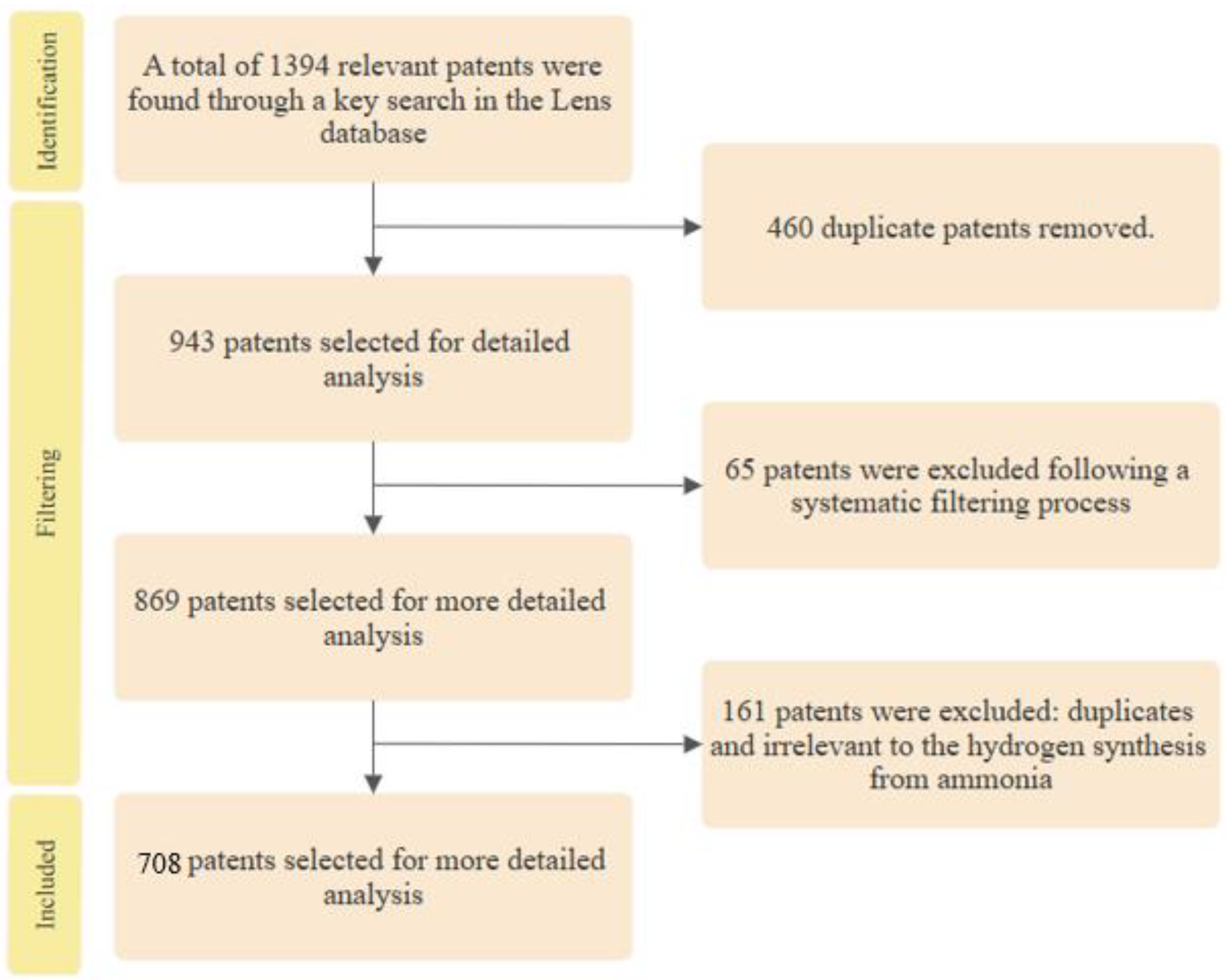
Figure 2.
Flowchart of patent classification.
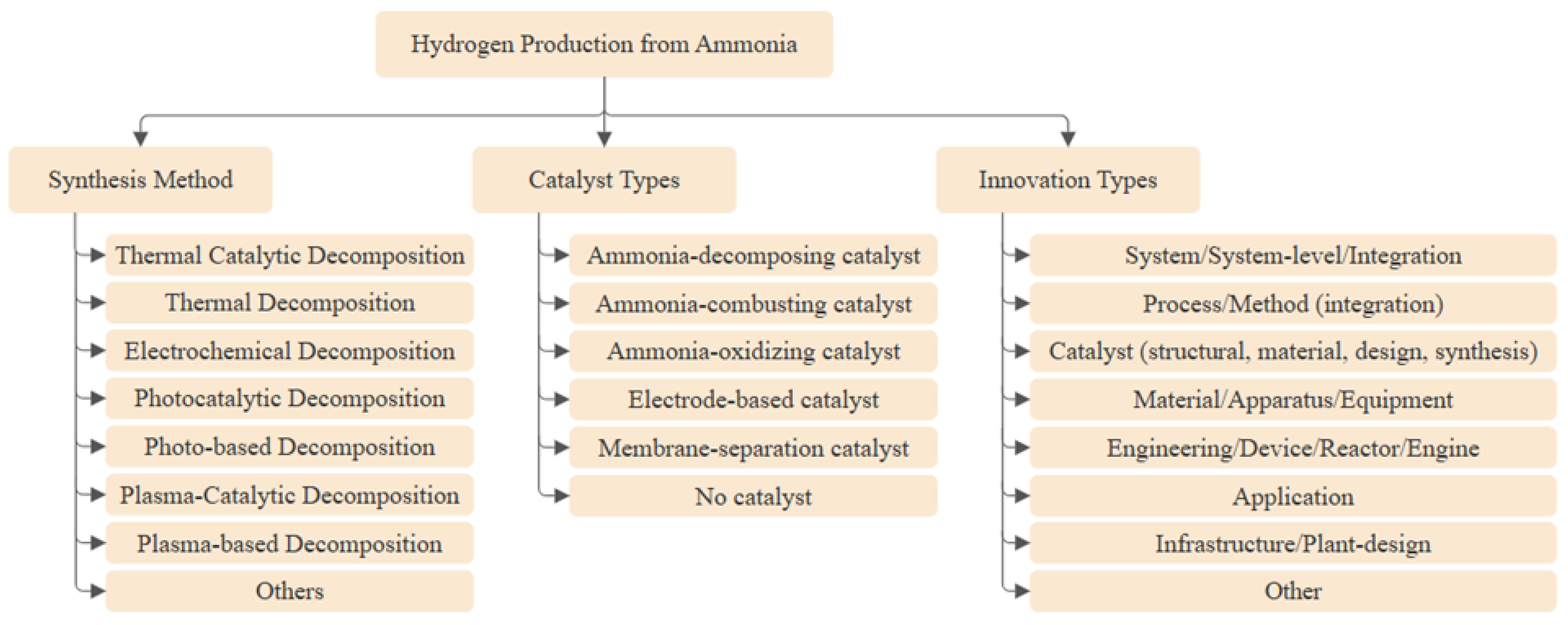
Figure 3.
(a) Percentage distribution of patents across individual catalyst categories, (b) Percentage distribution of patents exhibiting multi-catalyst overlap.
Figure 3.
(a) Percentage distribution of patents across individual catalyst categories, (b) Percentage distribution of patents exhibiting multi-catalyst overlap.
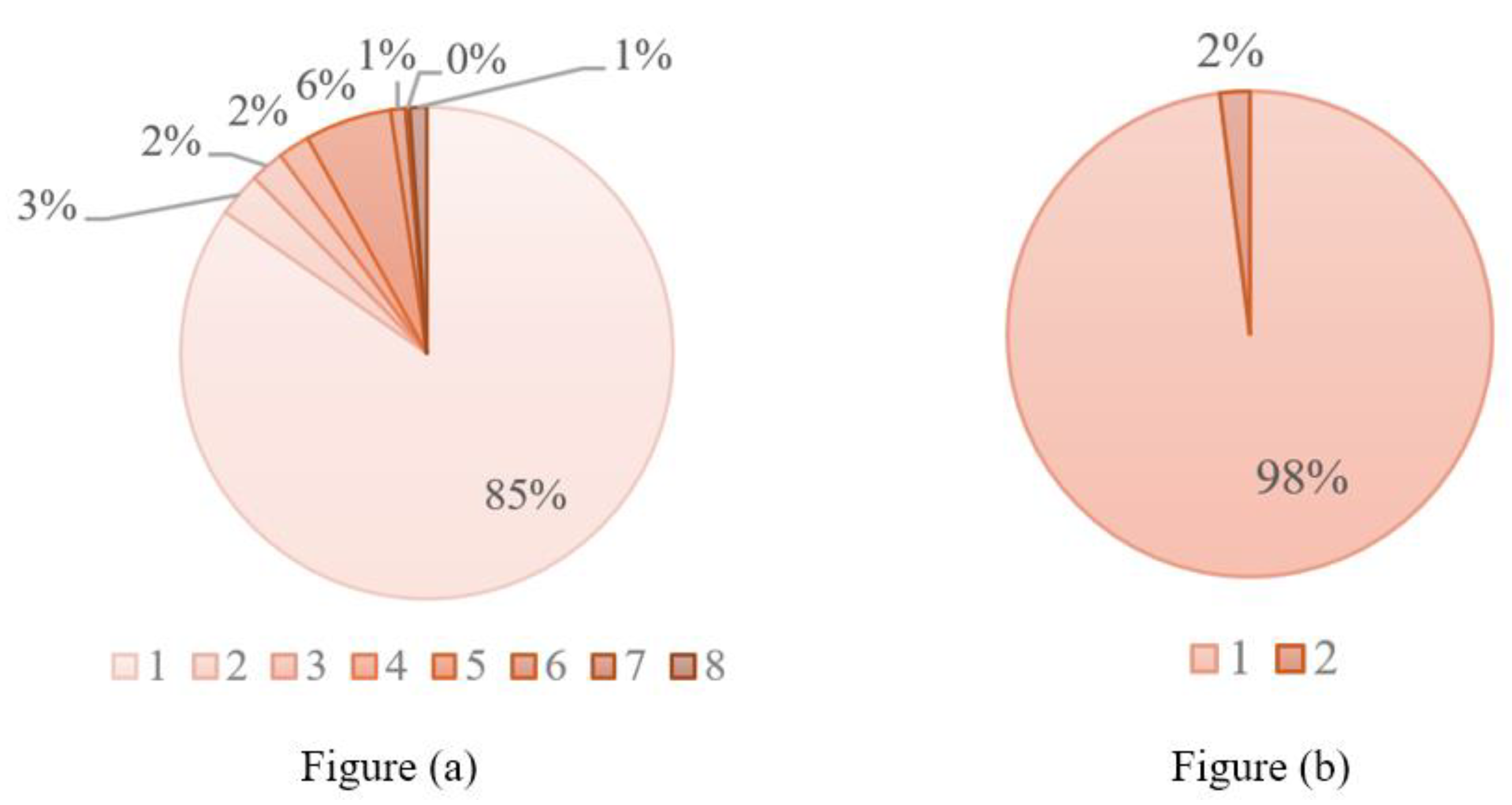
Figure 4.
Distribution of patents across ammonia decomposition synthesis methods.
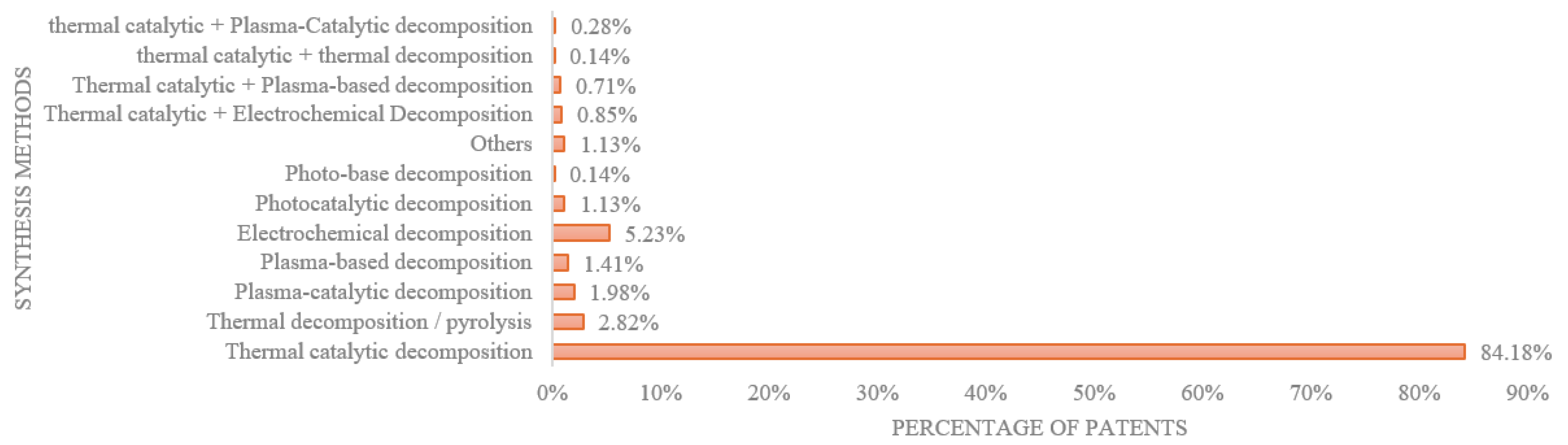
Figure 5.
(a) Percentage distribution of patents across individual catalyst categories, (b) Percentage distribution of patents exhibiting multi-catalyst overlap.
Figure 5.
(a) Percentage distribution of patents across individual catalyst categories, (b) Percentage distribution of patents exhibiting multi-catalyst overlap.
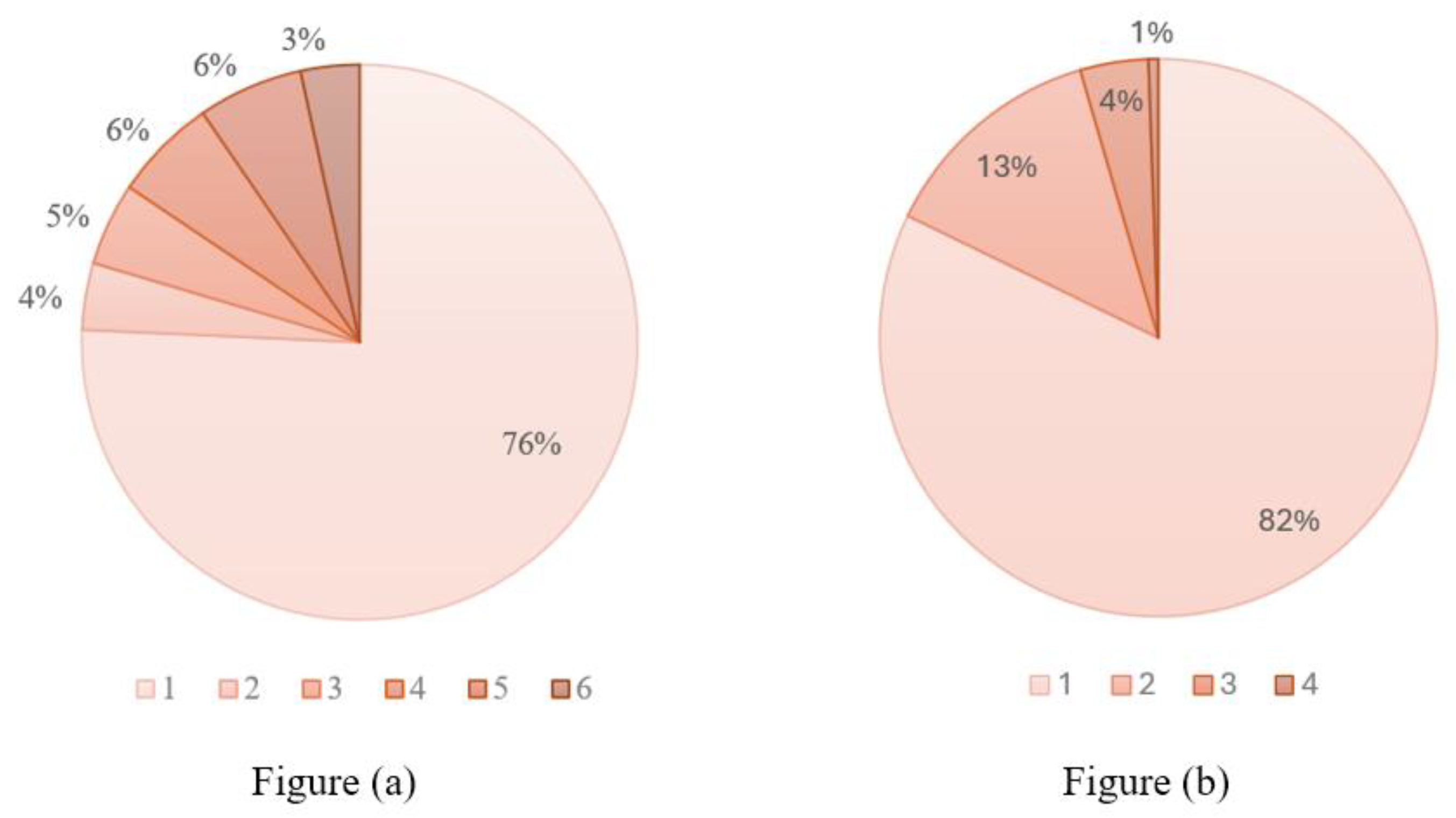
Figure 6.
Percentage of patents classified by catalyst type and catalyst-type combinations, showing the overwhelming predominance of ammonia-decomposing catalyst technologies.
Figure 6.
Percentage of patents classified by catalyst type and catalyst-type combinations, showing the overwhelming predominance of ammonia-decomposing catalyst technologies.
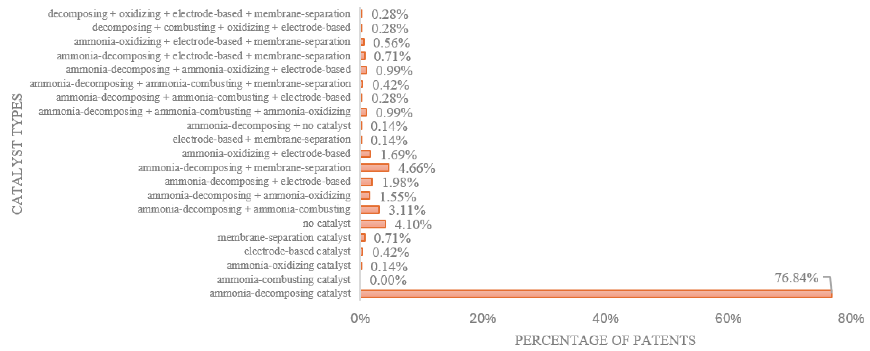
Figure 7.
(a) Percentage distribution of patents across each individual innovation-type category, showing how patents are concentrated in specific innovation domains, (b) Percentage distribution of patents with overlapping innovation types, indicating the number of patents that span multiple innovation categories.
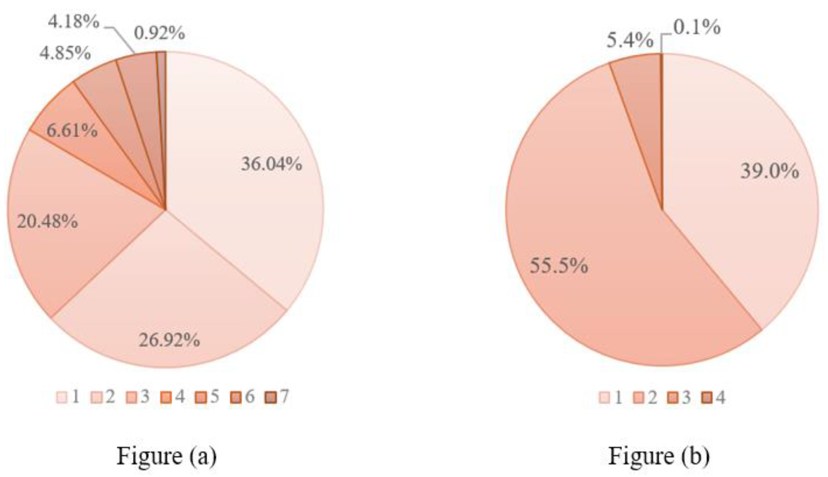
Figure 8.
Patent percentages for innovations in one or more categories.
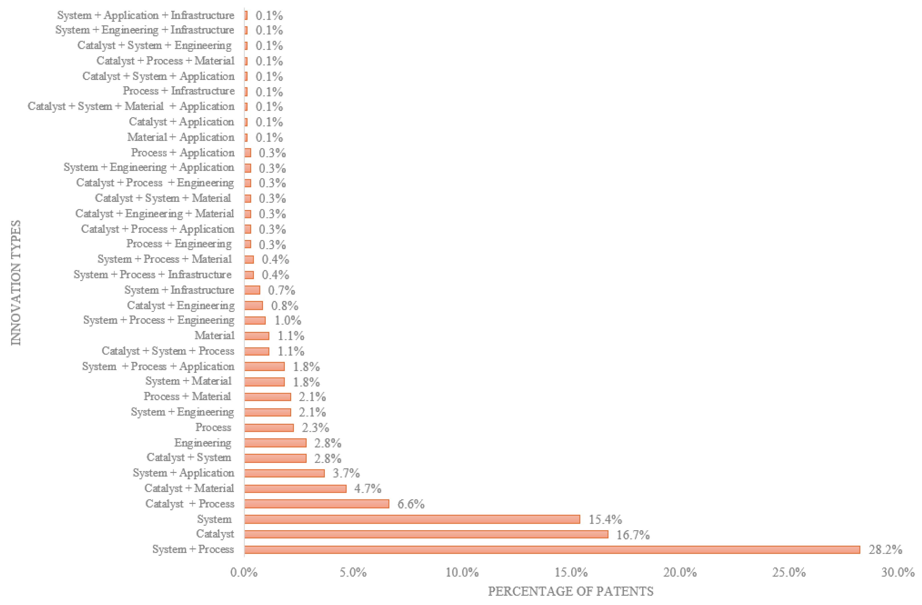
Figure 11.
Average backward citation (cited patent count) over time by document type.
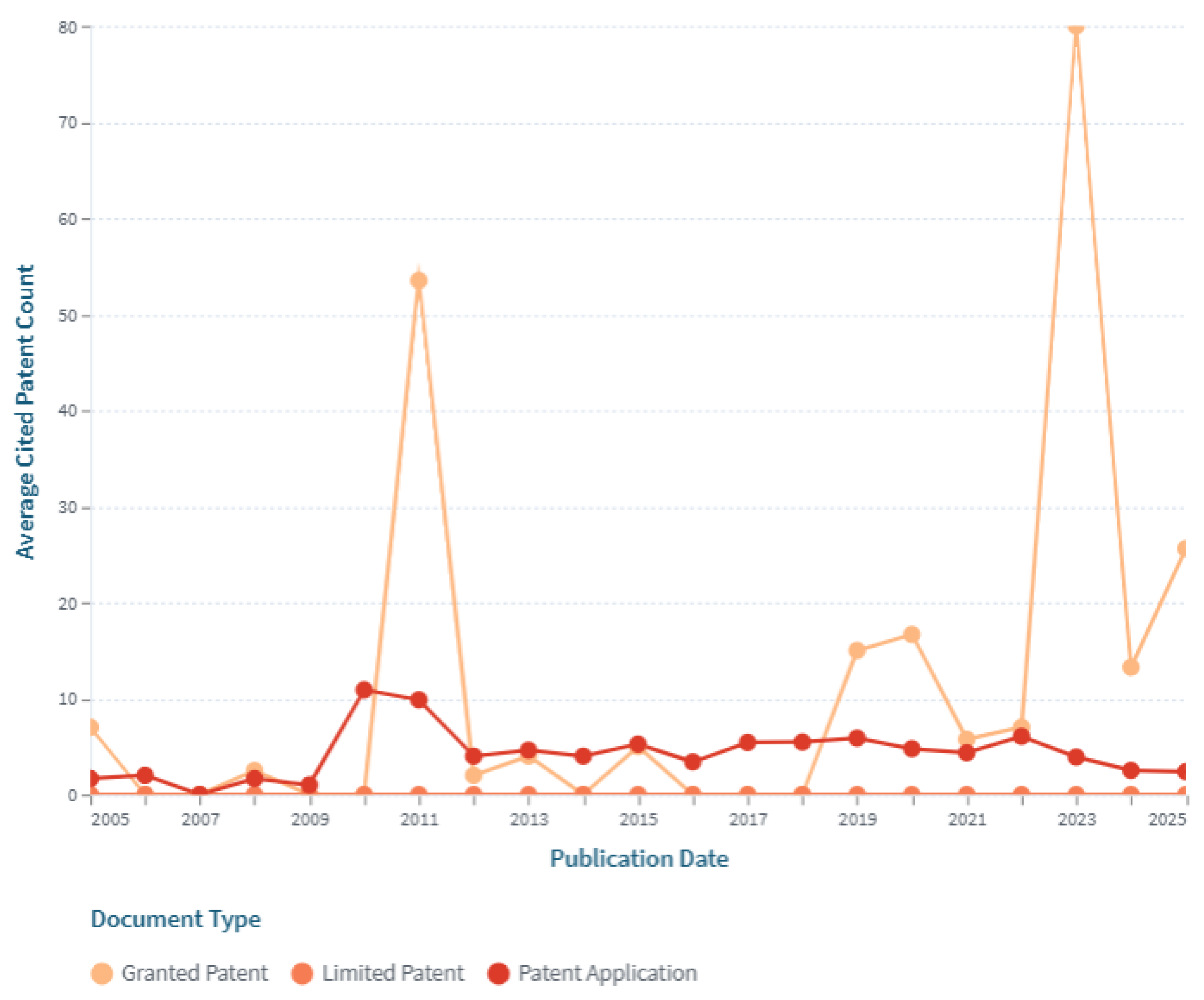
Figure 12.
Average Inventor Count Over Time by Document Type.
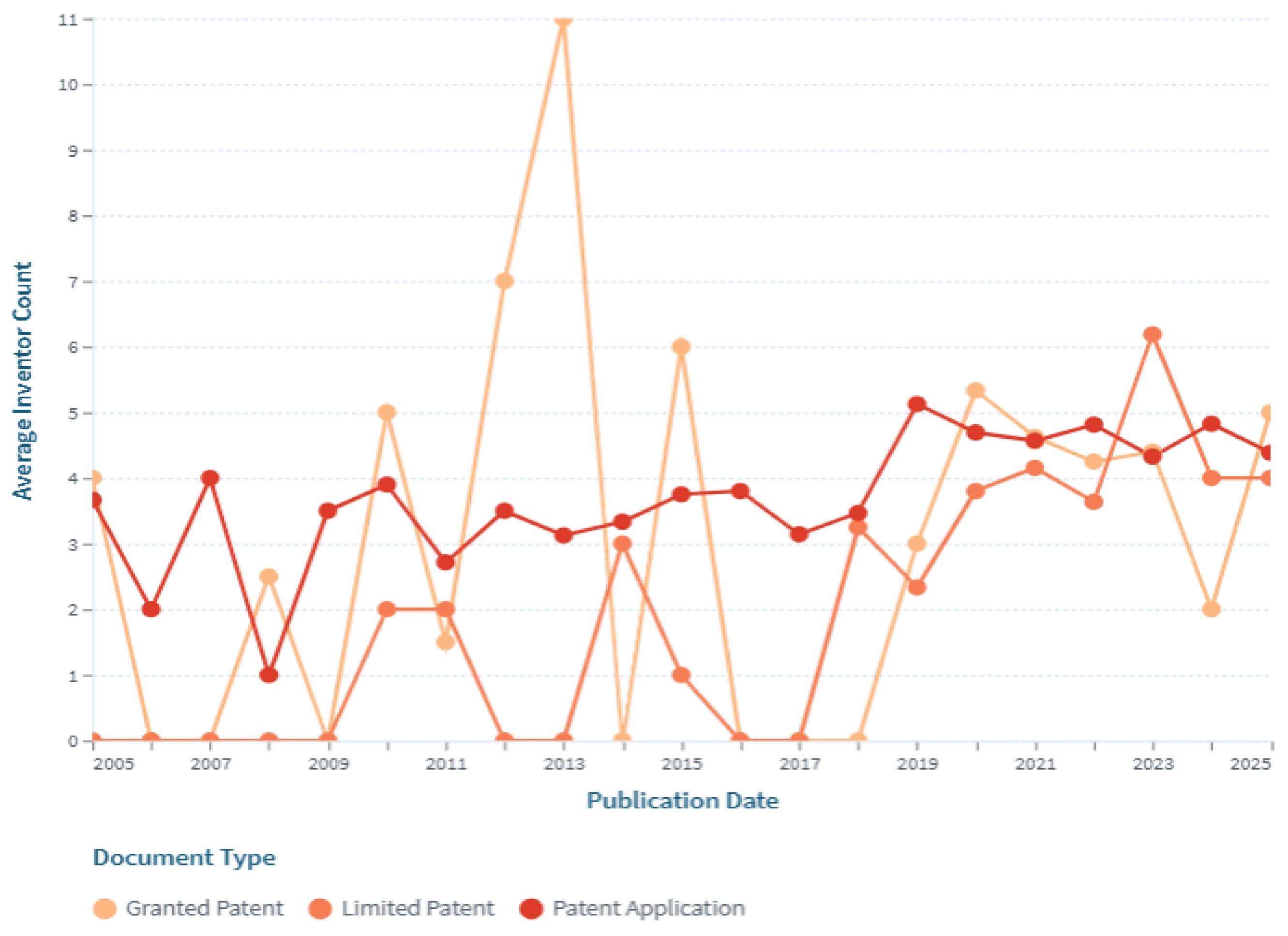
Figure 13.
The trend of published patents from each country in each year.
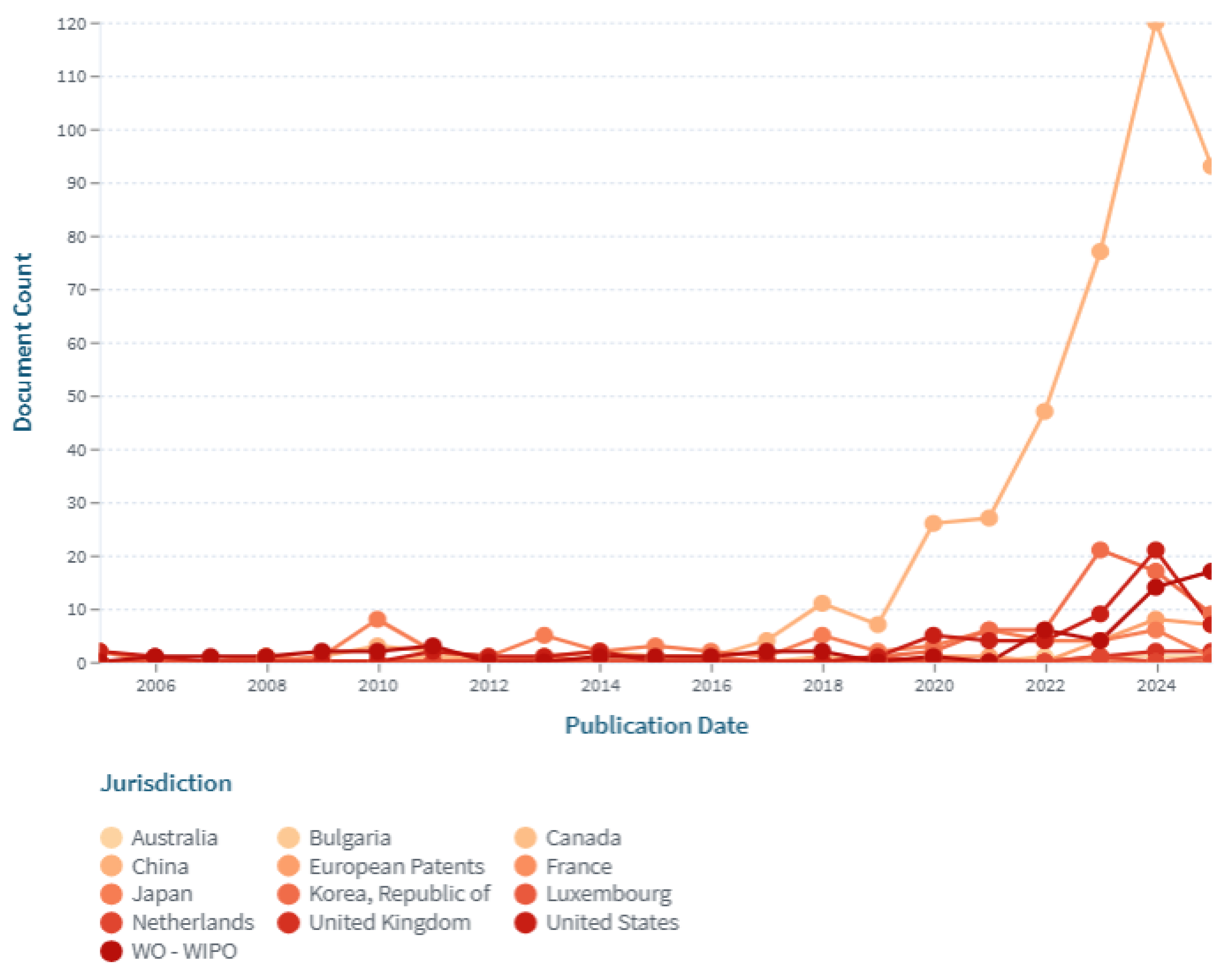
Figure 14.
Number of patents invented by different inventors.
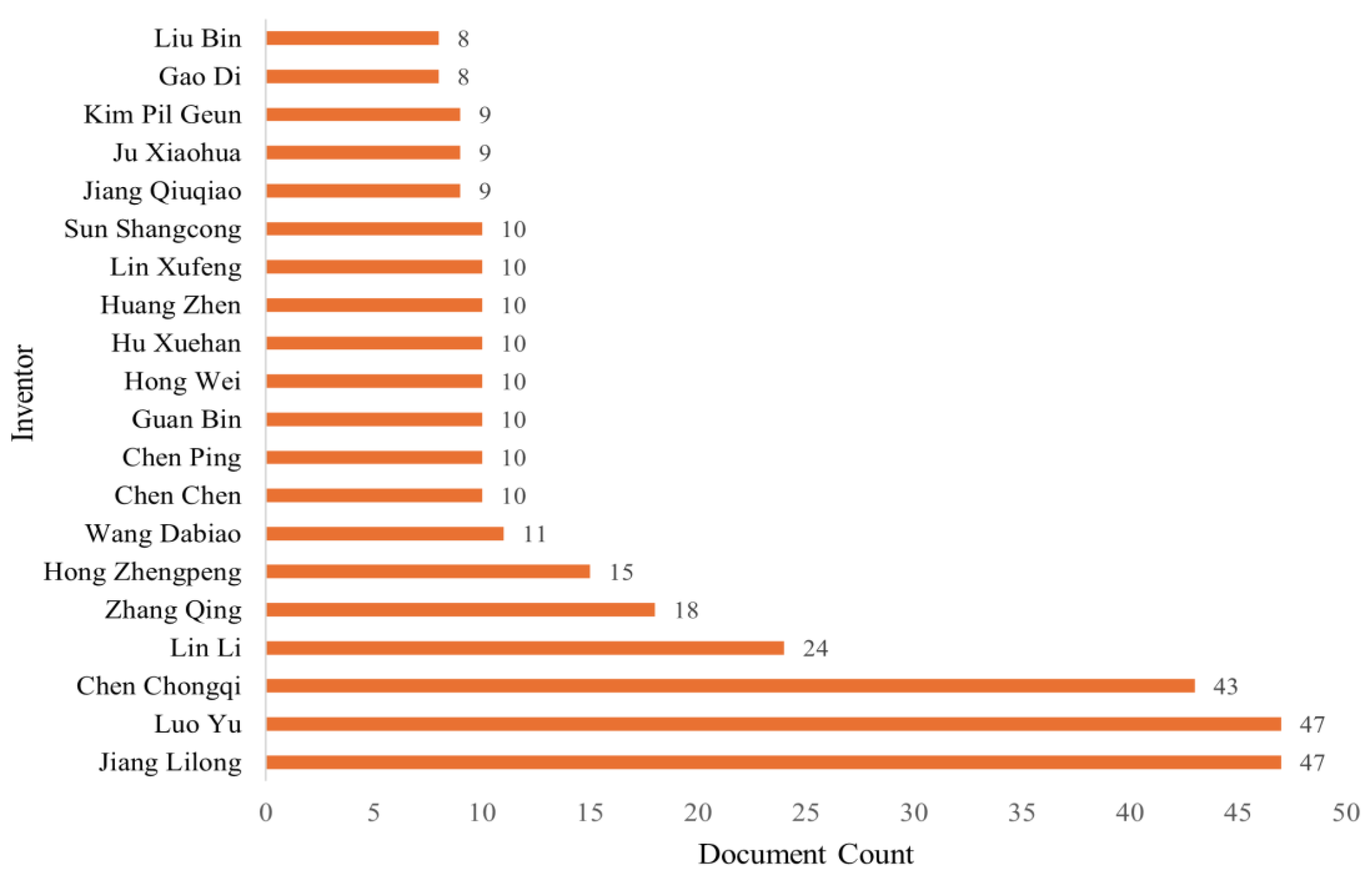
Figure 15.
Number of patents by different applicants.
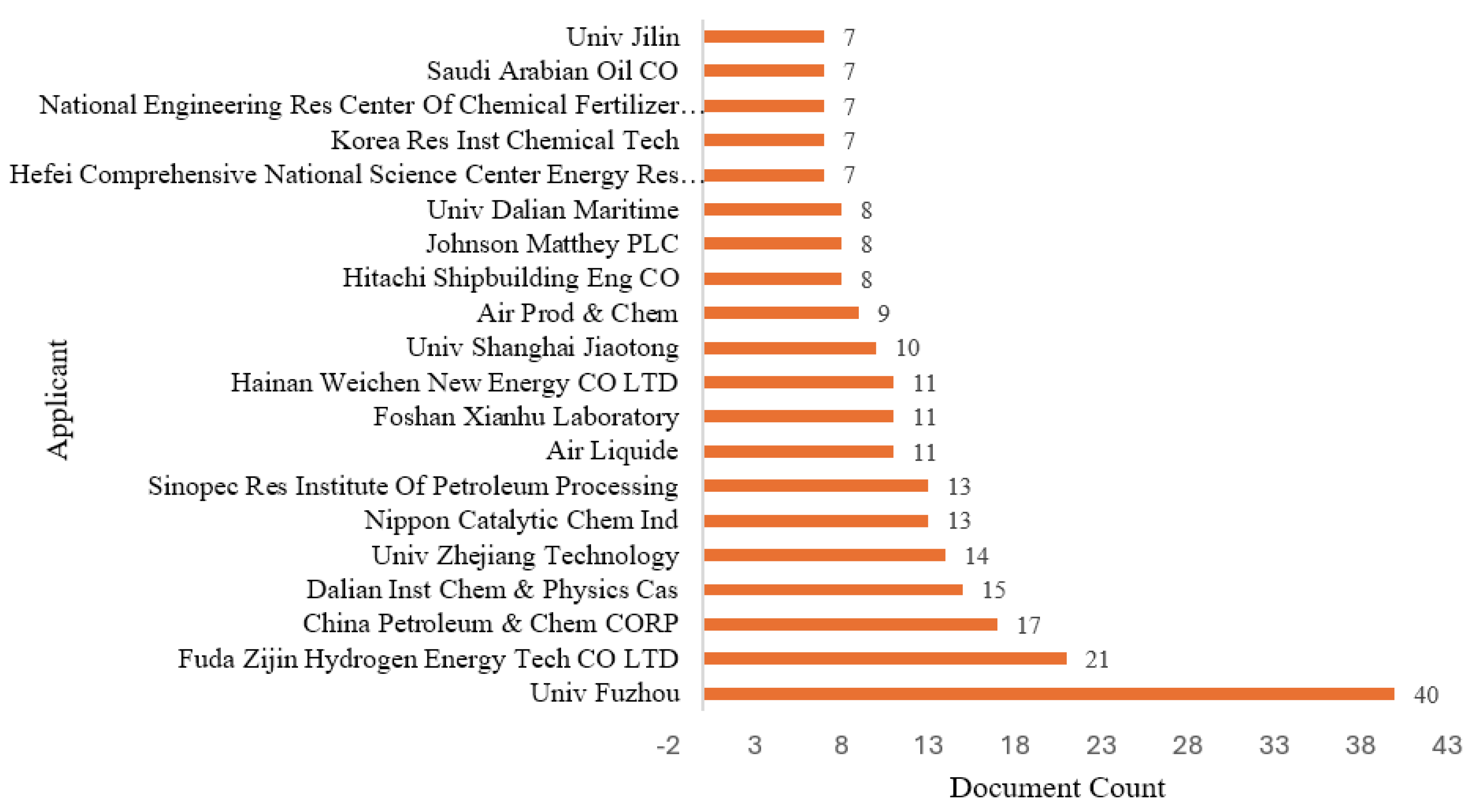
Figure 16.
Number of patents owned by different owners.
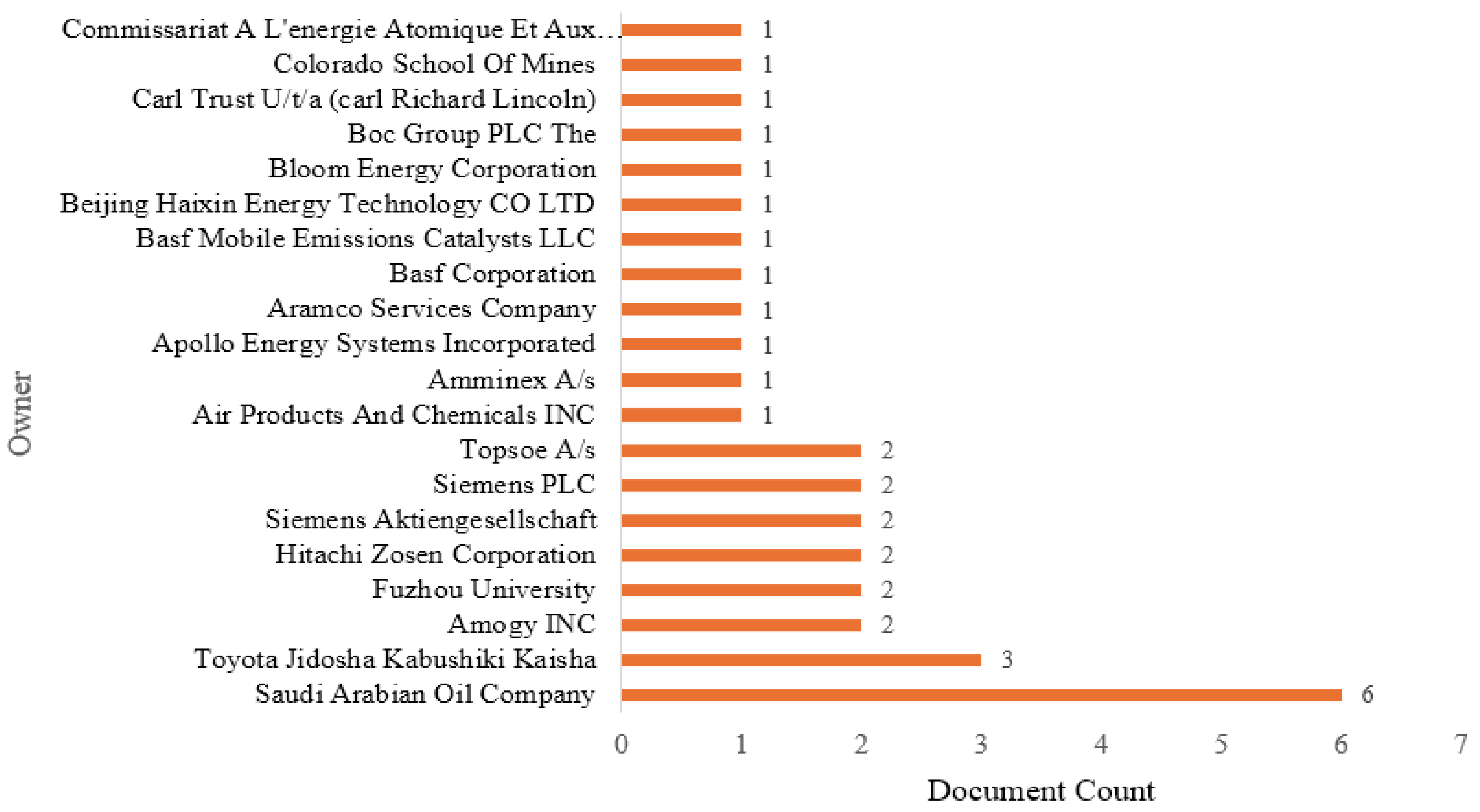
Figure 17.
Number of patents from different jurisdictions.
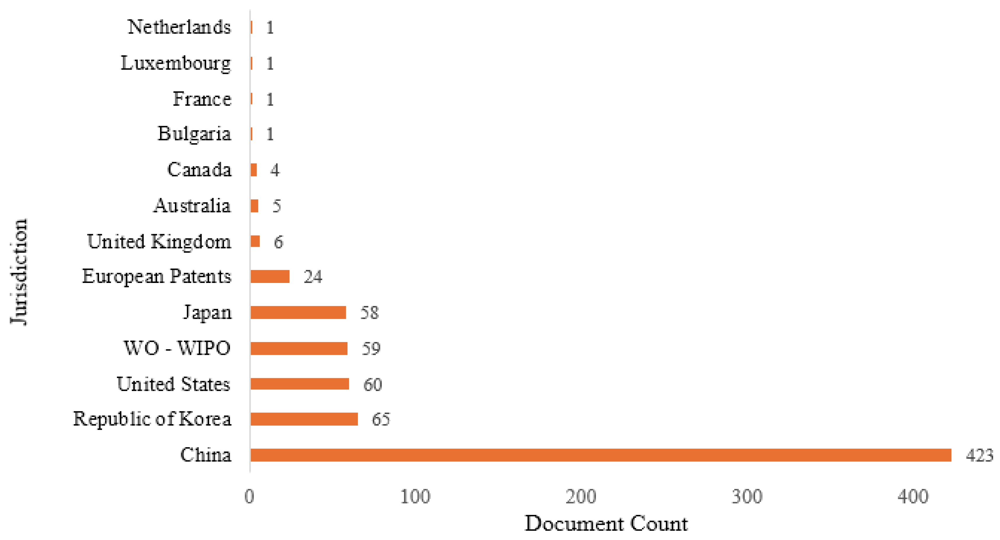
Table 1.
LENS database patent search keywords.
| Category | Keyword |
|---|---|
| Process | Search (hydrogen production, produce hydrogen, hydrogen generation, generate hydrogen, hydrogen synthesis, hydrogen recovery, hydrogen separation, hydrogen extraction) [Title, Abstract, Claims] |
| Method | Search (Decomposition ammonia, Ammonia electrolysis, catalytic ammonia, Plasma-based ammonia, Ammonia cracking, Ammonia dehydrogenation, ammonia combustion, Electrochemical ammonia, conversion ammonia, dissociation ammonia, Ammonia hydrogen production) [Title, Abstract, Claims] |
| IPC Code | Search (B01J23/02, B01J23/10, B01J23/46, B01J35/60, B0137/02, B01J37/08, B01J37/30, C01B3/04, C01C1/00, C01C1/02, C01C1/04, C25B1/02, F02D19/06, H01M8/06) [IPCR Classification Code] |
Table 2.
Description of each hydrogen production method from ammonia.
| Synthesis Methods | Description |
|---|---|
| Thermal Catalytic Decomposition | In this process, ammonia is heated in the presence of metal-based catalysts (such as Ru, Ni, or Fe) that speed up the high-temperature cracking of NH₃ into H₂ and N₂, producing hydrogen. This is the most popular path in international patents and the quickest way to implement ammonia cracking technologies for immediate hydrogen uses. |
| Thermal Decomposition | Catalysts are not necessary for ammonia to crack at high temperatures; heat alone drives the endothermic breakdown mechanism. Although less effective, this technique offers simpler system designs and is helpful for understanding combustion-assisted or low-catalyst paths. |
| Electrochemical Decomposition | Ammonia is converted to hydrogen in electrochemical reactions that utilize electrodes and an applied electrical potential. It can help achieve its long-term decarbonization objectives by facilitating low-temperature hydrogen synthesis and compatibility with renewable electricity. |
| Photocatalytic Decomposition | Ammonia is transformed into hydrogen at low temperatures using light-responsive catalysts (such TiO₂-based materials) that absorb photons and create reactive electrons and holes. It is an example of a new green technology that could eventually be used to generate hydrogen using the sun. |
| Photo-based Decomposition | Ammonia breaks down when it is directly exposed to light or when it is chemically activated, which doesn’t need a solid catalyst. They employ light energy to break chemical bonds instead. It helps in determining where to focus research efforts and how to approach problems in innovative ways. |
| Plasma-Catalytic Decomposition | Ammonia molecules are broken down more efficiently when catalytic surfaces are combined with plasma discharge. As a result, the process can occur at lower temperatures. Reactions become more efficient when the temperature is lowered. This demonstrates hybrid approaches that may be able to link current and emerging technologies. |
| Plasma-based Decomposition | Strong electrons and radicals produced by non-thermal plasma break the bonds in ammonia, enabling the production of hydrogen without the need for catalysts. It highlights state-of-the-art research on non-thermal, low-temperature breakdown, which may be a promising area for future creative collaborations. |
| Others | This group includes novel or non-traditional ammonia breakdown processes that don’t fall into the usual synthesis pathways. This ensures that it records outlier technology and identifies no new approaches that may be missed. |
Table 3.
Description of each catalyst type used in patents.
| Catalyst Types | Description |
|---|---|
| Ammonia-decomposing catalyst | Catalysts that are made to break down NH₃ into H₂ and N₂, like Ru/Al₂O₃, Ni-based alloys, and nitrides. This is the most common type of catalyst in the dataset and the most important one for industrial cracking systems. It is also crucial to adopt technology immediately. |
| Ammonia-combusting catalyst | Catalysts that help ammonia partially oxidize or burn, which are typically employed to provide heat for self-sustaining decomposition or to lower NOx levels. It lets ammonia crackers heat themselves, which helps generate hydrogen in a method that consumes less energy and is more transportable. |
| Ammonia-oxidizing catalyst | Catalysts enabling the ammonia oxidation reaction (AOR), typically for electrochemical hydrogen production or wastewater ammonia removal, coupled with H₂ generation. It is essential for the electrochemical synthesis of hydrogen at low temperatures and is beneficial for systems that integrate renewable energy sources. |
| Electrode-based catalyst | Electrodes for electrolysis or electrocatalytic ammonia breakdown contain catalytic materials such as Pt-, Co-, or Fe-based electrocatalysts. This makes the system work more efficiently and effectively. It works with novel concepts for fuel cells and electrolyzers, supporting the development of green hydrogen technology. |
| Membrane-separation catalyst | Catalytic membranes or membrane-coupled systems are used to pick out H₂ from the ammonia-cracked gas stream. It makes hydrogen purer and the system more efficient, which is useful for PEFC applications and ammonia refueling infrastructure. |
| No catalyst | These patents do not employ a catalyst at all. Instead, they use only heat, plasma, or mechanical techniques to break down ammonia, demonstrating alternative methods that do not require the use of catalytic materials. |
Table 4.
Description of each innovation type focused on patents.
| Innovation Types | Description |
|---|---|
| System/System-level/Integration | These patents cover ways to make hydrogen that use reactors, purifiers, heat exchangers, controllers, and safety equipment. Their strength is that they show how well the whole system works instead of just one part. This group is very important because it shows how to build efficient cracking stations and future hydrogen hubs. |
| Process/Method (integration) | Process-method patents show new ways to make ammonia-cracking systems work better by improving reaction conditions, optimizing heat flows, and refining operating modes. These new ideas are important because they improve performance with very little extra hardware. It can be used it to build hydrogen systems that are more efficient and reliable at a lower cost. |
| Catalyst (structural, material, design, synthesis) | These inventions show progress in catalyst design, from new material compositions to more advanced surface engineering and synthesis routes, all of which are meant to speed up the breakdown of ammonia. Their significance is in facilitating elevated conversion rates at reduced temperatures. |
| Material/Apparatus/Equipment | These inventive concepts focus on better system components, such as advanced heat exchangers, selective membranes, strong reactor housings, and efficient burners, which make the whole process work better. Their importance comes from making the system more stable and giving hardware the ability to support new ammonia-cracking technologies. |
| Engineering/Device/Reactor/Engine | Patents in this group are for new device designs, like miniaturized reactors, cracking modules that can be mounted on engines, and lightweight hydrogen generators. These new ideas make ammonia-to-hydrogen technology more useful. So, they make it possible to use hydrogen in mobile, off-grid, or distributed energy systems. |
| Application | These patents show new ways to use hydrogen from ammonia in fuel cells, mobility systems, industrial processes, and refueling networks. Their value comes from turning scientific progress into useful solutions; to show early-adopter sectors that can speed up the use of hydrogen. |
| Infrastructure/Plant Design | Infrastructure patents introduce innovative layouts and system designs for hydrogen plants, storage networks, and refueling stations. Such innovations are important because they enable efficient, integrated hydrogen ecosystems. |
| Other | This category captures unconventional or emerging innovations that fall outside standard classifications. It is important because it flags disruptive or future-shaping ideas early. |
Table 8.
Published patents from each country in each year.
| Country | |||||||||||||
|---|---|---|---|---|---|---|---|---|---|---|---|---|---|
| Year | AU | CN | JP | Netherland | Bulgaria | EP | KR | UK | CA | France | Luxembourg | US | WIPO |
| 2005 | 0 | 0 | 2 | 0 | 0 | 0 | 0 | 0 | 0 | 0 | 0 | 2 | 0 |
| 2006 | 0 | 0 | 0 | 0 | 0 | 0 | 0 | 0 | 0 | 0 | 0 | 1 | 1 |
| 2007 | 0 | 0 | 0 | 0 | 0 | 0 | 0 | 0 | 0 | 0 | 0 | 0 | 1 |
| 2008 | 0 | 0 | 0 | 0 | 0 | 1 | 1 | 0 | 1 | 1 | 0 | 0 | 1 |
| 2009 | 0 | 1 | 1 | 0 | 0 | 0 | 0 | 0 | 0 | 0 | 0 | 0 | 2 |
| 2010 | 0 | 3 | 8 | 0 | 0 | 0 | 0 | 0 | 0 | 0 | 0 | 0 | 2 |
| 2011 | 0 | 2 | 2 | 0 | 0 | 0 | 0 | 0 | 0 | 0 | 0 | 2 | 3 |
| 2012 | 0 | 0 | 1 | 0 | 0 | 1 | 0 | 0 | 0 | 0 | 0 | 1 | 0 |
| 2013 | 1 | 1 | 5 | 0 | 0 | 0 | 1 | 0 | 0 | 0 | 0 | 1 | 0 |
| 2014 | 0 | 2 | 2 | 0 | 0 | 0 | 0 | 0 | 1 | 0 | 0 | 2 | 1 |
| 2015 | 0 | 1 | 3 | 0 | 0 | 1 | 0 | 0 | 0 | 0 | 0 | 0 | 1 |
| 2016 | 0 | 1 | 2 | 0 | 0 | 0 | 1 | 0 | 0 | 0 | 0 | 0 | 1 |
| 2017 | 0 | 4 | 1 | 0 | 0 | 0 | 0 | 0 | 0 | 0 | 0 | 0 | 2 |
| 2018 | 0 | 11 | 5 | 0 | 0 | 0 | 0 | 0 | 1 | 0 | 0 | 0 | 2 |
| 2019 | 0 | 7 | 2 | 0 | 0 | 0 | 1 | 1 | 0 | 0 | 0 | 1 | 0 |
| 2020 | 1 | 26 | 3 | 0 | 0 | 1 | 2 | 0 | 0 | 0 | 0 | 5 | 1 |
| 2021 | 0 | 27 | 6 | 0 | 0 | 1 | 6 | 0 | 0 | 0 | 0 | 4 | 0 |
| 2022 | 0 | 47 | 4 | 0 | 1 | 0 | 6 | 0 | 0 | 0 | 0 | 4 | 6 |
| 2023 | 1 | 77 | 4 | 1 | 0 | 4 | 21 | 1 | 0 | 0 | 0 | 9 | 4 |
| 2024 | 1 | 120 | 6 | 0 | 0 | 8 | 17 | 2 | 0 | 0 | 0 | 21 | 14 |
| 2025 | 1 | 93 | 1 | 0 | 0 | 7 | 9 | 2 | 0 | 0 | 1 | 7 | 17 |
| Total | 5 | 423 | 58 | 1 | 1 | 24 | 65 | 6 | 3 | 1 | 1 | 60 | 59 |
Disclaimer/Publisher’s Note: The statements, opinions and data contained in all publications are solely those of the individual author(s) and contributor(s) and not of MDPI and/or the editor(s). MDPI and/or the editor(s) disclaim responsibility for any injury to people or property resulting from any ideas, methods, instructions or products referred to in the content. |
© 2026 by the authors. Licensee MDPI, Basel, Switzerland. This article is an open access article distributed under the terms and conditions of the Creative Commons Attribution (CC BY) license (http://creativecommons.org/licenses/by/4.0/).
Copyright: This open access article is published under a Creative Commons CC BY 4.0 license, which permit the free download, distribution, and reuse, provided that the author and preprint are cited in any reuse.


