
Submitted:
31 December 2025
Posted:
01 January 2026
You are already at the latest version
Abstract
Simulator‑based digital twins are widely used in robotics education and industrial development to accelerate prototyping and enable safe experimentation. However, they often hide implementation details that are essential for understanding, diagnosing, and correcting system failures. This paper introduces a technology‑independent model‑based design framework that provides students with full visibility of the computational mechanisms underlying robotic controllers while remaining feasible within a 150‑hour undergraduate course. The approach relies on representing controller behavior using networks of Extended Finite State Machines (EFSMs) and their stacked extension (EFS2M), which unify all abstraction levels of the control architecture—from low‑level reactive behaviors to high‑level deliberation—under a single formal model. A structured programming template ensures traceable, optimization‑free software synthesis, facilitating debugging and enabling self‑diagnosis of design flaws. The framework includes real‑time synchronized simulation, transparent switching between virtual and physical robots, and a smart data logger that captures meaningful events for model updating and error detection. Integrated into the Intelligent Robots course, the system supports topics such as kinematics, control, perception, and SLAM while avoiding dependency on specific middleware such as ROS~2. Results over three academic years indicate that students gain a deeper understanding of controller internals, and demonstrate improved ability to reason about system errors and their causes. The proposed environment thus offers an effective methodology for teaching end‑to‑end robot controller design through transparent, simulation‑driven digital twins.
Keywords:
digital twin
; extended finite state machines
; stacked state machines
; model-based design
; robotics education
; real-time simulation
; robot control architecture
; behavior modeling
; software synthesis
; fault detection and self-diagnosis
1. Introduction
Simulator-based digital twins streamline the development, deployment, and operation of robotic and industrial systems. These systems are typically specified with formal behavioral models that rely on hierarchy and abstraction to manage complexity. As a result, both industry and students often favor digital-twin workflows to build monitoring and control software and to quickly deliver tangible results.
However, a major drawback is that design details can be obscured, which makes failures harder to diagnose and correct. Engineers -—and increasingly artificial intelligence (AI) assistants– must therefore understand the underlying formal models and the key technologies in the development toolchain. Building this foundation is essential for efficient systems and for addressing failures effectively.
In robotics, core technologies converge within the digital twin: a robot’s data model, often linked to a simulator, and its control software. Robot development thus includes both the physical robot and its digital counterpart.
Time constraints force most robotics courses to emphasize a limited subset of robot design while still enabling hands-on laboratory work. In this paper, we describe how we designed a course that covers the controllers across the full stack from a single computational model, still allowing practical experience and, critically, providing visibility into the internal workings of robotic systems. The latter supports debugging and fault analysis, though it typically increases learning time. To fit a 150-hour course with 50 contact hours, we introduced a simulator-based digital twin of an elementary mobile robot and a simplified model-to-software framework.
The Intelligent Robots course (within an AI undergraduate program) reviews kinematics for wheeled mobile robots and manipulator arms, as well as low-level control, assuming no prior robotics background. The course focuses on behavior modeling with state machines and demonstrates, through code examples, how to achieve real-time simulation, model updates, and synchronization between simulation and physical systems.
The contributions of this work are: (i) a single, simple model that spans all abstraction levels of robotic controllers; (ii) a programming template for synthesizing software from system models; and (iii) a set of models and their software counterparts supporting real-time synchronized simulation of a digital twin that can also act as the controller for the physical robot. Building on [1], we further present a model-based design system that subsumes features of well-known models, including the ability to represent autonomous, intelligent agents, and we provide practical guidelines for synthesizing software manually or with AI assistance.
The paper is organized as follows. Section 2 reviews system-modeling techniques and AI-assisted software generation, as well as related courses and development environments. Section 3 details the critical aspects of robotic controllers in the course setting. We then discuss the course experience and outcomes.
2. State of the Art
Our primary goal was to create a technology-agnostic, model-based design (MBD) framework that minimizes the learning curve while covering the knowledge and skills required to develop control software for industrial machinery and robots. MBD uses formal, machine-readable models that can be simulated, verified, and deployed atop middleware that links application software with visualization, monitoring tools, simulators, and the actual plant or robot.
Contemporary software development increasingly leverages AI for code generation. Yet large language models (LLMs) do not inherently capture model intent and may produce incomplete or incorrect code, increasing the verification burden. Engineering education must therefore provide practical, end-to-end experience, even in introductory courses, which often means carefully scoped lab activities.
2.1. Model-Based Design
Model-based systems engineering (MBSE) has become essential for coping with heterogeneous hardware, distributed software, real-time constraints, and safety-critical requirements. MBSE captures requirements, architecture, behavior, and verification artifacts across the lifecycle, improving consistency, traceability, and multidisciplinary integration [8,9]. MBD uses such models to represent behavior, enable verification, generate code automatically, and accelerate deployment and maintenance.
Models can be tailored to functional and nonfunctional requirements –for example, in manufacturing automation [2] and satellite systems [3]– and translated to executable platforms such as PauWare [4] that support simulation, execution tracing, and runtime verification. Statecharts [5], a common formalism for concurrent hierarchical EFSMs (HCEFSMs), help designers reason about behavior, explore states comprehensively, and scale to complex systems.
Single-state state machines (SSSMs) are sometimes used to encapsulate behavior designed with different methods. An ASML study [6] reported that SSSMs comprised over 25% of 1,500 industrial models and were relatively stable over time.
While code generation depends on both the model and the tools, many common models can be compiled into a model intermediate representation (MIR) to support efficient scheduling, simulation, and code generation in tools like Simulink and Ptolemy-II [7].
In practice, many engineers are comfortable coding ad hoc state machines but are less familiar with designing software from formal models. Projects evolve, so designs must remain adaptable. We address this by leveraging networks of simple EFSMs that emulate statechart features and can be implemented without specialized libraries or environments.
The framework must also account for ROS 2, now a dominant open middleware in industrial robotics, offering real-time–friendly communication, DDS-based security, cross-platform support, and modularity [10,11]. ROS 2 aligns well with formal modeling frameworks such as Timed Rebeca for verifying concurrency, timing, and safety properties and for bridging analysis, simulation, and deployed code [12,13]. Industry-focused ROS 2 frameworks improve modularity and reuse, support rapid development, and provide unified, real-time–capable interfaces [14]. Simulators –most notably Gazebo (tight ROS integration) and Unity-based XR environments– enable simulation-driven development and digital twins that support early validation, model refinement, and faster commissioning [15]. While this ecosystem increases environment complexity, our work focuses on HCEFSMs implemented with concurrent EFSMs and a direct link to raw code. We also relate HCEFSMs to the hierarchical state machines (HSMs) and behavior trees (BTs) commonly used in ROS 2 projects.
2.2. Software Generation
We distinguish programming from software synthesis. Programming translates a model into a particular language and introduces optimizations; software synthesis prioritizes a systematic translation that preserves traceability from the model to the code.
LLMs can generate code [18,19,20], but may propagate errors and security issues from training data [21]. They tend to perform well on simpler problems, struggle with extended reasoning, and often optimize for compilability over robustness, motivating combined correctness-and-security evaluations such as CodeSecEval [22]. Social and technical biases in automatic generation have been documented [23,24,25]. Automatic translation with the help of LLMs has limited accuracy [26], with success rates ranging from 2 to 47% [27], and is not reliable without thorough human review [28,29], complemented by testing and targeted prompts that reduce errors.
Fine-tuning can improve generation quality at lower computational cost [30,31,32,33], but interactive clarification is typically required [34], and performance degrades with overly long or noisy prompts [35]. While top models achieve student-level exam performance in programming [36,37], human experts still excel at structured reasoning and quality control.
Our approach converts formal state-machine diagrams directly into executable code, reducing ambiguity, bias, and translation errors. LLMs can then be used as transducers given paired examples (diagram → code), but they may insert “false optimizations” (e.g., reorganizing code or adding unnecessary initializations) that mask model flaws. We therefore prefer synthesis patterns that maximize model–code traceability and embed self-diagnostics.
2.3. Robotics Education
According to Educations.com, there are 127 undergraduate AI programs worldwide (76 in Europe, 26 in the UK, and 6 in Spain), including ours at the Universitat Autònoma de Barcelona. Many programs include a 6 ECTS (≈150 hours) robotics course with ≈50 contact hours. Our course must introduce robotics fundamentals [38,39] while focusing on intelligent robots [40], covering kinematics and dynamics, controllers, perception (notably vision), execution of predefined plans, SLAM and Kalman filtering, and AI links for perception and decision making—topics that often demand an entire course [41,42] or a dedicated master’s program.
Leading universities (e.g., Oxford, Stanford, UC3M, EPFL) offer compatible overviews, while others (e.g., Berkeley, Imperial, Harvard, NTU, NUS, Caltech, and UPC) provide specialized courses in robotics and AI. Affordable robot platforms enable rich student labs [43]. Digital twins extend this work beyond the lab with safe, risk-free testing. Popular simulators –Player/Stage Gazebo [44], CoppeliaSim [45], and Webots [46]– offer model libraries and support building twins for the lab robots. In our case, we use in-house developed mobile robots and their digital twins that consist of the corresponding robot model and a few high-level data (Figure 1). We also have an arm robot from UR for which we use the built-in model in CoppeliaSim.
Low-level controllers can directly drive actuators, but complex procedures are best programmed atop ROS [47]. In fact, some introductory courses on robotics use ROS [42] and there are educational resources based on ROS [48,49,50]. While we include only a practical ROS example, our programming model mirrors ROS node organization and can generate ROS code. Unlike ROS pub–sub timing, our execution can satisfy stricter time requirements.
Inspired by Ptolemy II [51], our computational model represents behavior as a network of EFSMs communicating via signals in a cycle-by-cycle execution, enabling accurate timing. We simplify Ptolemy II to reduce errors and ease code generation and debugging. Prior work has proposed correct-by-construction behaviors with built-in recovery [52] and fault-handling architectures [53].
Our course content is organized around hands-on modules but emphasizes technology-agnostic controller thinking and robust signal handling -—present, out-of-range, and absent—- so that components embed error detection and recovery.
3. Course Contents
The course covers foundational material common to many offerings: kinematic models of wheeled mobile robots (with emphasis on differential drive) and robotic arms (including inverse kinematics), as well as open-loop and closed-loop control with PID controllers. It also introduces image processing (OpenCV [54]), AI-based detection (YOLO [55]), SLAM, and the Kalman filter.
The differentiating element is the software development process: behavior is modeled as an EFSM network and paired with an ad hoc simulator so students can see how systems work internally and where failures originate. The remainder of this section details the computational model and the real-time execution model used to synchronize the digital twin with reality.
3.1. Behavior Modeling
Because EFSMs underlie more complex models (statecharts, HSMs, and BTs), any of these can be transformed into EFSMs. We thus represent the system as a set of EFSMs executing in parallel. Unlike plain FSMs, EFSMs carry an extended state: a control state plus a data store retained across cycles.
Figure 2 shows a programmable counter with clock input, two inputs (P and b), one output (e), and an internal counter C. Diagram labels define transition conditions and associated actions. Decision nodes (e.g., ) partition cases to ensure coverage. All activated actions are conceptually concurrent within a cycle. Delayed assignments (e.g., ) update at the next cycle, while the next control state is determined by the graphical transitions. Designers must avoid conflicting assignments to the same signal (e.g., and simultaneously).
Hierarchy arises when a state contains a subordinate machine (Figure 3, top). In our implementation (Figure 3, bottom), we simplify semantics by running master and slave EFSMs in parallel, sharing variables and I/O and coordinating with active/ready handshake signals. This pattern reproduces statechart behavior while making priorities and continuations explicit and observable.
Arrows coming from composite states that do not originate from stop states of the subordinate machine like can be assigned various meanings, since it is necessary to determine whether the actions of the subordinate machine should take effect and with what priority in case of conflict and also whether, upon returning to the master state, the subordinate machine will remember the current state or start from the initial one again. In the format of the diagrams at the top of Figure 3, this should be specified explicitly, as is done, for example, in statecharts.
To simplify, the hierarchy is implemented so that the slave machines work in parallel with the masters, sharing variables and input and output. The hierarchy is established through a handshake protocol with activation and readiness signals. Thus, when the master state machine reaches the SUB state, the active signal is set to true so that the slave machine exits the IDLE state in the next cycle.
When the slave machine returns to IDLE, the ready signal returns to true so that the master can continue. This reproduces the same behavior as the arrival at END in the slave machine depicted above and the exit arc from the octagon in the composite state of the master machine.
The semantics associated with exit arcs that do not wait for the subordinate EFSM to return to an inactive state can be easily simulated in the composite state part, with an extra decision node, as can be seen in the lower right part of Figure 3. On the subordinate machine side, the designer must consider all situations and decide, for each state , whether to suspend the corresponding activity and add a decision node active and, in that case, whether to restart the activity in that state or return to IDLE. In this way, there are no errors in interpreting which actions are taken. It should be noted that it can be monitored when the subordinate machine continues with the activity and the master has exited SUB because the ready signal of the subordinate will remain at false.
Thus, concurrent EFSMs can represent hierarchical machine behaviors such as statecharts and HSMs and BTs, which are more common in the field of robotics. In fact, in the case of BTs, it is even simpler, since the various nodes represent communication between machines working in parallel.
For intelligent behaviors, we extend EFSMs with a state stack (EFS2M) inspired by pushdown automata [56]. The EFS2M model adds a state stack and push, pop, and top operations and the corresponding graphical representation.
The EFS2M in Figure 4 generates a plan in case plan1() returns true, which consists of following a sequence of states, from to and GOAL. The plan appears in reverse order since the bubbles with state names that appear after the tip of an arrow are states that are pushed and, therefore, will be popped in the reverse order to which they were put on the stack.
In state there are three types of output arcs. The one that is born directly from the state bubble and that is activated with next1_1_2() is a regular arc that goes to the state at the top of the stack. That is, the hexagon at the end of the arrow indicates that the next state will be the one that is popped from the stack. The arc labeled with skip1_2() is born after a bubble that represents a pop operation on the state stack. If you want to indicate that it is completely emptied, you do not need to put as many bubbles as there are states on the stack, but it is enough to put a hexagon there, as shown in the arc abort1_1().
This model naturally represents the planning style of belief-desire-intention(BDI) agents [57], where intentions correspond to stacked plans and desires to the initial pushed states.
As mentioned, the computational model used is an EFSM network with implicit hierarchy, that is, the model does not include any explicit indication of subsumption of one component to another. The description of such a model includes that of the architecture of its system and that of the EFSMs it contains. The architecture diagram also indicates how the different components relate to each other and can be hierarchical. In this sense, this computational model is comparable to behavioral trees.
At the architectural level (Figure 5), we adopt a conventional three-tier stack for a mobile robot. L2 (deliberation) can host a BDI-like agent but, in our course, serves as a user-facing interface that selects missions (SWEEP, FOLLOW, NAVIGATE). L1 (execution) decomposes missions into L0 (reactive) primitives.
Each architectural element expands to one or more EFSM, i.e. multiple EFSMs may coexist per layer. Outputs are driven from state variables (Moore semantics) to prevent circular dependencies and order-sensitive updates. For example, Figure 6 shows the LIDAR sweep state machine part of the main state machine in L1.
3.2. EFS2M Software Generation
Modern control/embedded environments provide modeling, simulation, verification, and code generation—often bound to a specific middleware. A key advantage of EFSM/EFS2M networks is that their behavior can be coded directly in any language without special libraries.
3.2.1. EFS2M Programming Template
There are several ways to translate EFS2M diagrams into programs. They can be classified into those based on state machine interpreters and those that are hard coded. In the first case, the transition and output tables of the EFS2Ms are interpreted by a program that simulates them. In the second case, the simulator program calls specific functions for each EFS2M.
In our case, each state machine is an object of a class with methods to initialize (init) it and simulate its behavior. For the latter, it is divided into four phases: reading inputs (read_inputs), calculating the next extended state (plan), updating it (update), and writing outputs (write_outputs).
The programming of the input/output functions must be done specifically because they depend on the input and output devices used. For example, for the low-level code of the virtual robot, the input and output are via CoppeliaSim.
However, the functions of the methods init, plan and update depend only on the state machine, and therefore the code can be generated following a pattern of correspondence between the elements of the diagram and instructions for the corresponding method.
The patterns for these functions assume that all variables in the state machines are tuples of two values: the current value and the value in the next state. (This implementation is not the most efficient in terms of execution cost, but it is one of the most efficient in terms of engineering cost.)
The state stack is another component of the main state variable tuple that is only manipulated in the plan function if the corresponding diagram contains some element that indicates it, such as push and pop bubbles or empty or pop hexagons (to change to the state at the top of the stack).
These programming patterns are almost templates in which programmers only have to fill in the gaps. However, it is common to incorporate false optimizations [58] that, at best, have no serious effects such as masking coding errors or in the model.
Furthermore, there is no guarantee that premature optimizations are necessary, or that some micro-optimizations such as changes in the format of some data may have an effect on the final executable code, or that code that takes advantage of specific features of a programming language will be more efficient in terms of memory or time than code based on more general instructions.
Basically, it is not a question of programming state machines but of synthesizing their code and, therefore, respecting as much as possible the link between each element of the state machine diagram and the code that corresponds to it.
In this way, it is also possible to incorporate mechanisms that check, for example, if no transition is activated or if more than one is activated in a given cycle, or if an unexpected state is reached.
In this sense, the course insists on the fact that any error in the model must have associated code that reveals it. For example, the monitor function must allow the observation of variables, even if they do not have a defined value.
3.2.2. Software Synthesis
Given that EFS2M programming follows well-defined patterns, it is feasible to automate the process, which also avoids the problem of false optimizations.
Automatic code synthesis can be done algorithmically or with the support of AI. In fact, an EFS2M software generator was already available that read the XML of the models and generated the corresponding Lua code. However, the graphical representations of the models must be syntactically correct for the synthesis program to generate code and, in addition, variations in the input format and output language can imply significant modifications with a large associated cost.
The rise of programming assistants based on LLMs takes advantage of the fact that there is a good database of both algorithmic solutions to problems and programming of these algorithms. As has been seen, this does not mean that the generated code must be reviewed extensively.
However, in the particular case of behavioral models, it is not necessary for the LLM to be trained to correlate problems and algorithmic solutions but rather to correlate models with codes that follow a specific pattern.
In this sense, a series of examples have been created that pair EFS2M and the corresponding programs so that the AI assistant can generate an appropriate output for the target model that has a very high correlation with the given examples.
In experiments with several AI chats (ChatGPT, Copilot and DeepSeek) it has been observed that they all work well for simple cases where the input is a syntactically correct diagram. In fact, in these cases it is irrelevant whether the input is an image of the state machine or an XML or the output programming language.
In the case of images, synthesis works better because it does not depend on attributes of the objects in the drawing and, for example, arrow connections are established by proximity while, in the XML format, it depends on whether the two objects are linked or not.
It has also been observed that they tend to introduce false optimizations and corrections such as initializations not present in the models, which can mask behavioral errors.
In short, software synthesis programs generate code without false optimizations and, therefore, with reliable self-diagnosis, but they require inputs with clear graphical syntax and must adapt to each input and output format. AI chats, on the other hand, can work with any input and output, as long as the instructions include examples in the formats used, but they can reproduce the same problems that could be encountered with human programmers.
3.3. Real-Time Simulation
The execution model of state machines can be represented by a state machine (Figure 7) that cyclically repeats the phases of reading input data (SENSE), calculating the next extended state (PLAN), updating it (UPDATE) therefore moving to the next cycle, and writing primary outputs (ACT). This means that all machines in the system are always in the same phase.
This execution model links, to each state, the call to a specific function of all the state machines of the system and is easy to program in any programming language, which allows the implementation of the system simulation in any development environment.
In this EFSM, the variable C is a cycle counter, that is, it indicates how many transitions the state machines have made until the current cycle, the variable is the simulated time, which starts at 0 and the inputs T and provide the real time of the system where it is executed and the time step in each cycle. For simplicity, this time step is fixed and the condition for it to be executed in real time is that the execution time of each cycle is always less than or equal to .
To calculate the time elapsed in a cycle, there is the variable B (for “begin time”) that stores the reference of time at which each cycle begins. The state machine will remain in IDLE until . In this case, it has been chosen to increase B by instead of assigning it to the value of T to allow the excess execution time of previous cycles to be compensated for with subsequent cycles in which the system runs faster. However, it must be considered that there are systems that do not tolerate this soft real-time behavior.
In systems that work with very short execution times compared to , more than one cycle can be advanced per time step. In this case, cycles will be advanced until some calculation of the next state of some state machine of the system requires an external input. This information is stored in the variable X upon reaching the UPDATE state from PLAN, which is where the function step is called and returns this condition.
The variable I indicates the cycle number within the current period, so that signals that are events cease to be present when . In this sense, this must be taken into account when programming the read_inputs functions, since they are the ones that must distinguish between inputs that are events and others that are continuously present.
3.4. Simulation and Reality Synchronization
The simulated robot’s controller stack can be used for the real robot if it has part of the stack embedded and can communicate with the upper part. In our case (Figure 8, the stack is divided between L0 and L1 and, in addition, communication is maintained with both the virtual robot and the real robot so that the system can have both robots in operation.
For simplicity, when the real robot is connected, the responses sent to L1 are those of the real robot. This can generate discrepancies between the simulation and reality, since the simulated environment does not have to coincide with the real one, and there are no mechanisms implemented to make this update.
However, the fact that development can be completed in the simulated environment and that, in the laboratory, the connection with the real robot is transparent to the model, makes the experience more positive.
3.5. Model Update
One of the most common uses of AI is to analyze data to find patterns and features that are difficult to extract with algorithmic methods. This is also true for identifying parameters in controllers’ models. The course does not go so far and considers how a data logger for the robot should be made so that the data in the robot behavior model can be updated, and to detect system errors.
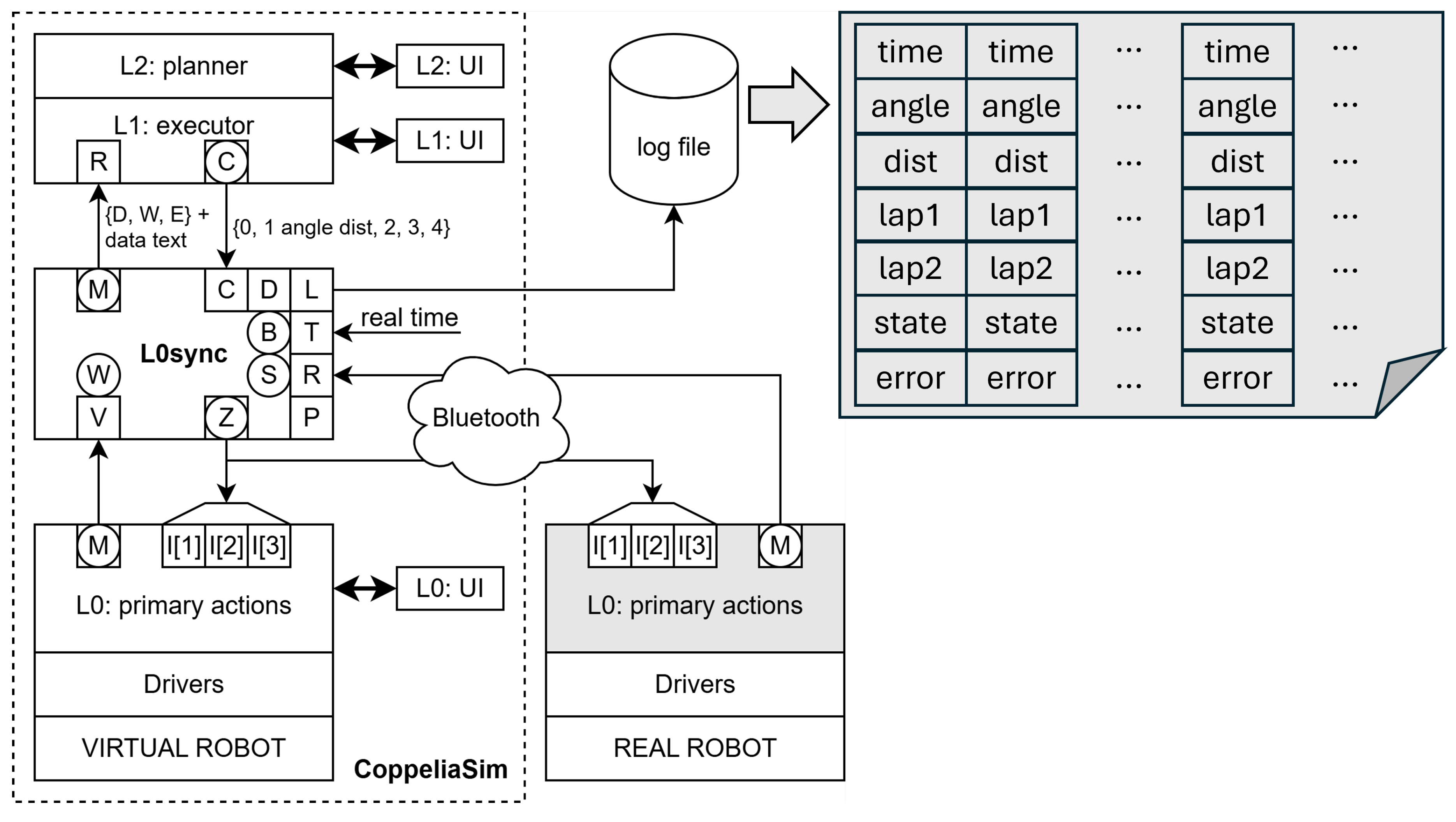
Various data loggers are considered, from those that store everything to smarter ones that only record events of interest, whether errors or pre-processed data to update the model parameters. The smart data logger presented in Figure 9 stores only data related to the robot’s motion operations to be able to determine how well the real-time simulation adapts to the real robot and alarms related to out-of-context messages and timeout situations.
In the log file, records are stored labeled with the real time (T), the rotation and displacement that it had to make and the time at which the first response (lap1) of one of the robots and the second (lap2) of the other was registered. To know which one it is, you need to see if the state is AHEAD (the first response comes from the virtual robot), BEHIND (the first response comes from the real robot) or SYNC, in which they arrived at the same time. In case the responses are not coherent or if any of them arrive after a certain time, an error is generated.
4. Conclusions
Developing software for industrial monitoring, control, and robotics requires substantial knowledge and skill. Simulator-based digital twins help practitioners focus on behavior, but can hide details that matter when systems fail. We presented a development environment that couples a digital twin with a transparent computational model: any system behavior can be described as an EFS2M network.
Compared with statecharts, HSMs, and BTs, the proposed modeling style is simpler to learn, robust by construction, and easy to implement without specialized middleware. To be widely useful, however, it should align with the tools most engineers use, notably ROS 2. Our initial motivation was pedagogical: cover a broad, practice-oriented spectrum so students can see and reason about the full path from model to executable controller, both in simulation and on the real robot.
Over three years of teaching, students reported positive hands-on experiences and demonstrated the ability to adapt to projects using different modeling styles and toolchains, while requesting greater design freedom. From an educational standpoint, future work should include parallel examples implemented in other environments to ease transfer. From a research perspective, we will continue to embed self-diagnosis and error management in the generated code to detect both model and synthesis issues early.
Funding
This research received no external funding.
Data Availability Statement
Course material and software are available upon request.
Acknowledgments
The author thanks Jordi Guerrero for building the robot and carrying out the tests; Ismael Chaile, Pragna Das, Joaquín Saiz-Alcaine and Daniel Rivas for their contributions to various versions of the physical and virtual robots over the years; Marc Serra-Asensio for his contribution to AI assisted software synthesis of models, and Carlos García-Calvo for sharing with me the teaching of the Intelligent Robots course.
Conflicts of Interest
The author declares no conflicts of interest.
Abbreviations
The following abbreviations are used in this manuscript:
| AI | Artificial Intelligence |
| BDI | Belief–Desire–Intention |
| BT | Behavior Tree |
| DDS | Data Distribution Service |
| ECTS | European Credit Transfer System |
| EFSM | Extended Finite State Machine |
| EFS2M | Extended Finite State Stack Machine |
| FSM | Finite State Machine |
| HCEFSM | Hierarchical Concurrent Extended Finite State Machine |
| HSM | Hierarchical State Machine |
| LLM | Large Language Model |
| MBD | Model-Based Design |
| MBSE | Model-Based Systems Engineering |
| MIR | Model Intermediate Representation |
| PID | Proportional–Integral–Derivative Controller |
| ROS, ROS 2 | Robot Operating System (versions 1 and 2) |
| SLAM | Simultaneous Localization and Mapping |
| SSSM | Single-State State Machine |
| XR | Extended Reality |
| YOLO | You Only Look Once |
References
- Ribas-Xirgo, L. State Machine Model of a Controller System for an Educational Mobile Robot. International Workshop on Physical Agents, 4–5 Sep. 2025, Cartagena (Spain).
- Vogel-Heuser, B.; Schütz, D.; Frank, T.; Legat, C. Model-driven engineering of Manufacturing Automation Software Projects – A SysML-based approach. Mechatronics, 24(7), 2014, 883–897, ISSN 0957-4158. Doi:10.1016/j.mechatronics.2014.05.003. [CrossRef]
- Center, K. Describing and Deploying Satellite Behaviors Using Rules-based Statecharts. Small Satellite Conference, 2014. URL: https://digitalcommons.usu.edu/smallsat/2014/IntellSoftware/2/.
- Cariou, E.; Brunschwig,L.; Le Goaer, O.; Barbier. F. A software development process based on UML state machines. 2020 International Conference on Advanced Aspects of Software Engineering (ICAASE), Nov 2020, Constantine, France. pp.1—-8. [CrossRef]
- Harel, D. Statecharts: A Visual Formalism for Complex Systems. Sci. Comput. Programming 8, 1987, 231–274.
- Yang, N.; Cuijpers, P.; Schiffelers, R.; Lukkien, J.; Serebrenik, A. Single-state state machines in model-driven software engineering: an exploratory study. Empirical Software Engineering, 26(12), 2021. [CrossRef]
- Su, Z.; Wang, D.; Yang, Y.; Yu, Z.; Chang, W.; Li, W. MDD: A Unified Model-Driven Design Framework for Embedded Control Software. In IEEE Transactions on Computer-Aided Design of Integrated Circuits and Systems, 41(10), 3252–3265, Oct. 2022. [CrossRef]
- Pasupuleti, S. Model-Based Systems Engineering (MBSE) for the Design and Integration of Complex Robotics Systems. ESP Journal of Engineering & Technology Advancements, 3(3): 126–132, 2023. Available at: https://espjeta.org/Volume3-Issue3/JETA-V3I7P116.pdf.
- Zhang, L.; Chen, Z.; Laili, Y.; Ren, L.; Deen, M.J.; Cai, W.; Zhang, Y.; Zeng, Y.; Gu, P. MBSE 2.0: Toward More Integrated, Comprehensive, and Intelligent MBSE. Systems, 13(7), 584, 2025. DOI:10.3390/systems13070584. Available at: https://www.mdpi.com/2079-8954/13/7/584. [CrossRef]
- Open Robotics. ROS – Robot Operating System: Home and ROS 2 releases. 2024–2025 updates. Available at: https://www.ros.org/.
- Pagare, T. The Future of Robotics Simulation and ROS 2 in 2025. LinkedIn Article, May 29, 2025. Available at: https://www.linkedin.com/pulse/future-robotics-simulation-ros-2-2025-tejas-pagare-gh03e/.
- Trinh, H.H; Sirjani, M.; Ciccozzi, F.; Masud, A.N.; Sjödin, M. Modelling and Model-Checking a ROS2 Multi-Robot System using Timed Rebeca. ArXiv, 2025. URL: https://arxiv.org/abs/2511.15227.
- Dust, L.; Gu, R.; Mubeen, S.; Ekström, M.; Seceleanu, C. A model-based approach to automation of formal verification of ROS 2-based systems. Frontiers in Robotics and AI, 12, 2025. [CrossRef]
- Sarraf, G. ROS 2 Control for Custom Robots: Mastering Real-Time Robot Control. ThinkRobotics Blog, Sep 3, 2025. Available at: https://thinkrobotics.com/blogs/learn/ros-2-control-for-custom-robots-mastering-real-time-robot-control.
- Flores González, J.M.; Coronado, E.; Yamanobe, N. ROS-Compatible Robotics Simulators for Industry 4.0 and Industry 5.0: A Systematic Review of Trends and Technologies. Appl. Sci. 2025, 15, 8637. [CrossRef]
- Naderhirn, M.; Köpf, M.; Mendler, J. Model based Design for Safety Critical Controller Design with ROS and Gazebo. ROSCon 2017. Accessible: https://roscon.ros.org/2017/presentations/ROSCon%202017%20Kontrol.pdf.
- Winiarski, T.; Kaniuka, J.; Giełdowski, D.; Ostrysz, J.; Radlak, K.; Kushnir, D. ROS-related Robotic Systems Development with V-model-based Application of MeROS Metamodel. 2025. DOI:10.48550/arXiv.2506.08706. Available at: https://arxiv.org/pdf/2506.08706v2. [CrossRef]
- Heller, M. LLMs and the rise of the AI code generators. InfoWorld. May 2023. URL: https://www.infoworld.com/article/2338500/llms-and-the-rise-of-the-ai-code-generators.html.
- Huynh, N.; Lin, B. A Survey On Large Language Models For Code Generation. ArXiv, 2025. [CrossRef]
- Jiang, J.; Wang, F.; Shen, J.; Kim, S.; Kim, S. A Survey on Large Language Models for Code Generation. ACM Trans. Softw. Eng. Methodol. July 2025. [CrossRef]
- AiverseInfo. How does a large language model (LLM) write code. AiverseInfo, 2023. URL: https://aiverseinfo.com/how-llm-writes-code/?amp=1.
- Wang, J.; Luo, X.; Cao, L.; He, H.; Huang, H.; Xie, J.; Jatowt, A.; Cai, Yi. Is Your AI-Generated Code Really Secure? Evaluating Large Language Models on Secure Code Generation with CodeSecEval. ArXiv. 2024. [CrossRef]
- Liu, Y; Chen, X; Gao, Y; Su, Z; Zhang, F; Zan, D; Lou, J; Chen, P.; Ho, T. Uncovering and quantifying social biases in code generation. In Proceedings of the 37th International Conference on Neural Information Processing Systems (NIPS ’23). Curran Associates Inc., Red Hook, NY, USA, Article 110, 2368–2380, 2023 URL: https://arxiv.org/pdf/2305.15377.
- Wang, C.; Li, Z.; Gao, C.; Wang, W.; Peng, T.; Huang, H.; Deng, Y.; Wang, S.; Lyu, M. Exploring Multi-Lingual Bias of Large Code Models in Code Generation. arXiv, 2024. URL: https://arxiv.org/abs/2404.19368.
- Huang, D.; Zhang, J.; Bu, Q.; Xie, X.; Chen, J.; Cui, H. Bias Testing and Mitigation in LLM-based Code Generation. ACM Trans. Softw. Eng. Methodol. 35, 1, Article 5 (January 2026), 31 pages. [CrossRef]
- Dou, S.; Jia, H.; Wu, S.; Zheng, H.; Wu, M.; Tao, Y.; Zhang, M.; Chai, M.; Fan, J.; Xi, Z.; Zheng, R.; Wu, Y.; Wen, M.; Gui, T.; Zhang, Q.; Qiu, X.; Huang, X.J. What is Wrong with Your Code Generated by Large Language Models? An Extensive Study. SCIENCE CHINA Information Sciences, 2025. [CrossRef]
- Pan, R.; Ibrahimzada, A.R.; Krishna, R.; Sankar, D.; Wassi, L.P.; Merler, M.; Sobolev, B.; Pavuluri, R.; Sinha, S.; Jabbarvand, R. Lost in Translation: A Study of Bugs Introduced by Large Language Models while Translating Code. In Proceedings of the IEEE/ACM 46th International Conference on Software Engineering (ICSE ’24). Association for Computing Machinery, New York, NY, USA, Article 82, 1–13. May 2024. [CrossRef]
- Liu, Y.; Le-Cong, T.; Widyasari, R.; Tantithamthavorn, C.; Li, L.; Le, X.-B.D.; Lo, D. Refining ChatGPT-Generated Code: Characterizing and Mitigating Code Quality Issues. ACM Trans. Softw. Eng. Methodol. 33, 5, Article 116 (June 2024), 26 pages. [CrossRef]
- Wang, Z., Zhou, Z., Song, D., Huang, Y., Chen, S., Ma, L., & Zhang, T. (2025). Towards Understanding the Characteristics of Code Generation Errors Made by Large Language Models. In Proceedings - 2025 IEEE/ACM 47th International Conference on Software Engineering, ICSE 2025 (pp. 2587-2599). (Proceedings - International Conference on Software Engineering). IEEE Computer Society. [CrossRef]
- Ma, Z.; Guo, H.; Chen, J.; Peng, G.; Cao, Z.; Ma, Y.; Gong, Y. LLaMoCo: Instruction Tuning of Large Language Models for Optimization Code Generation. ArXiv, abs/2403.01131, March 2024. [CrossRef]
- Tsai, Y. D.; Liu, M.; Ren, H. Code less, align more: Efficient LLM fine-tuning for code generation with data pruning. arXiv preprint arXiv:2407.05040, July 2024.
- Weyssow, M.; Zhou, X.; Kim, K.; Lo, D.; Sahraoui, H. Exploring Parameter-Efficient Fine-Tuning Techniques for Code Generation with Large Language Models. ACM Trans. Softw. Eng. Methodol. 34, 7, Article 204 (September 2025), 25 pages. [CrossRef]
- Chawre, H. Fine-tuning LLMs: Overview, methods, and best practices. Turing, March 2025. Accessible: https://www.turing.com/resources/finetuning-large-language-models.
- Mu, F.; Shi, L.; Wang, S.; Yu, Z.; Zhang, B.; Wang, C.; Liu, S.; Wang, Q. ClarifyGPT: A Framework for Enhancing LLM-Based Code Generation via Requirements Clarification. Proc. ACM Softw. Eng. 1, FSE, Article 103 (July 2024), 23 pages. [CrossRef]
- Tian, H.; Lu, W.; Li, T.; Tang, X.; Cheung, S.; Klein, J.; Bissyandé, T. Is ChatGPT the ultimate programming assistant: How far is it? ArXiv. Aug. 2023. URL: https://arxiv.org/abs/2304.11938.
- Bordt, S.; Luxburg, U. ChatGPT Participates in a Computer Science Exam. arXiv, March 2023. [CrossRef]
- Hou, W.; Ji, Z. Comparing Large Language Models and Human Programmers for Generating Programming Code. Adv. Sci. 2025, 12, 2412279. [CrossRef]
- Siegwart, R., Nourbaksh, I.R.: Introduction to Autonomous Mobile Robots. The MIT Press (2004).
- Graig, J.J.: Introduction to Robotics: Mechanics and Control. Pearson Education International (2005).
- Murphy, R.R. Introduction to AI Robotics. The MIT Press (2019).
- Gil-Vázquez, P.: Intelligent Robotics. Master in Artificial Intelligence. Universitat d’Alacant, Spain (2023).
- Sacré, P. Introduction to Intelligent Robotics. Master level. University of Liège, Belgium (2025).
- Čehovin Zajc, L., Rezelj, A., Skočaj, D.: Teaching Intelligent Robotics with a Low-Cost Mobile Robot Platform. In: Robotics in Education (RiE), Yverdon-les-Bains, Switzerland (May 2015).
- .
- Coppelia Robotics: CoppeliaSim, https://www.coppeliarobotics.com, last accessed 2025/7/7.
- Cyberbotics: Webots, https://cyberbotics.com/, last accessed 2025/7/7.
- Macenski, S., Foote, T., Gerkey, B., Lalancette, C., Woodall, W.: Robot Operating System 2: Design, architecture, and uses in the wild, Science Robotics 7 (May 2022).
- Cañas-Plaza, J., Perdices, E., García-Pérez, L., Fernández-Conde, J.: A ROS-Based Open Tool for Intelligent Robotics Education. In: Applied Sciences (2020). [CrossRef]
- Roldán-Álvarez, D., Mahna, S., Cañas, J.M.: A ROS-based Open Web Platform for Intelligent Robotics Education. In: Merdan, M., Lepuschitz, W., Koppensteiner, G., Balogh, R., Obdržálek, D. (eds) Robotics in Education (RiE 2021). Advances in Intelligent Systems and Computing 1359, Springer, Cham. (2022). [CrossRef]
- Martín-Rico, F.: A Concise Introduction to Robot Programming with ROS2, Chapman & Hall (2022).
- Ptolemaeus, C. (ed.): System Design, Modeling, and Simulation using Ptolemy II, Ptolemy.org (2014).
- Wong, K., Ehlers, R., Kress-Gazit, H.: Correct High-level Robot Behavior in Environments with Unexpected Events (2014). [CrossRef]
- Gharbi, A.: Faulty control system, In: Cognitive Systems Research 86, 101233 (2024) . [CrossRef]
- Bradski, G.: The OpenCV Library. In: Dr Dobb’s Journal of Software Tools, 2236121 (2000).
- Redmon, J., Divvala, S., Girshick, R., Farhadi, A.: You Only Look Once: Unified, Real-Time Object Detection. In: 2016 IEEE Conference on Computer Vision and Pattern Recognition (CVPR), 779–-788 (2016) . [CrossRef]
- Rivas, D.; Das, P.; Saiz-Alcaine, J.; Ribas-Xirgo, L. Synthesis of Controllers from Finite State Stack Machine Diagrams. IEEE International Conference on Emerging Technologies and Factory Automation, ETFA. p. 1179–1182, 2018.
- de Silva, L., Meneguzzi, F., Logan, B.: BDI agent architectures: A survey. In: Bessiere, C. (ed.) Proceedings of the 29th International Joint Conference on Artificial Intelligence (IJCAI 2020), International Joint Conferences on Artificial Intelligence Organization, pp. 4914–4921 (2020).
- Hyde, R. The Fallacy of Premature Optimization. ACM Ubiquity, 10(3), 2009.
Figure 1.
The real mobile robot and its virtual twin.
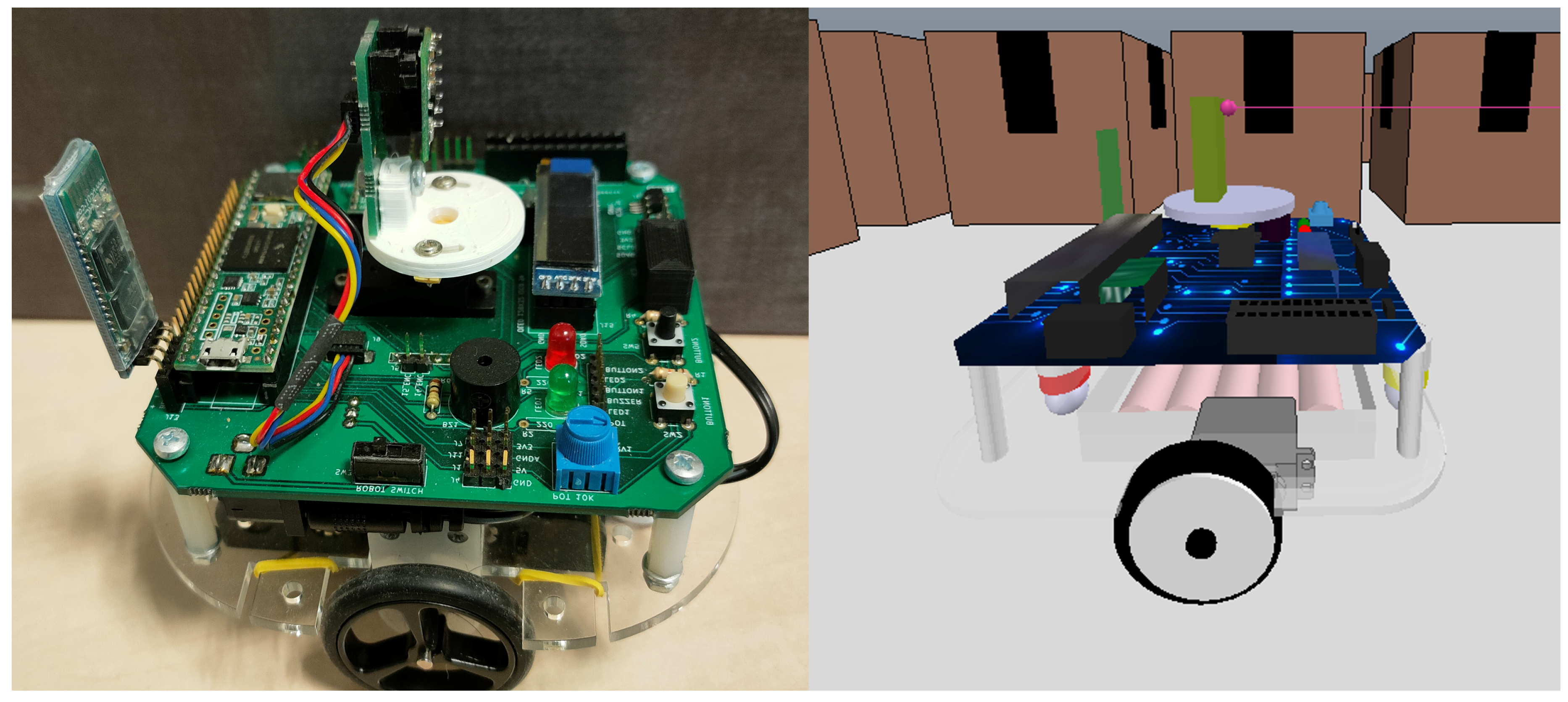
Figure 2.
A simple EFSM.
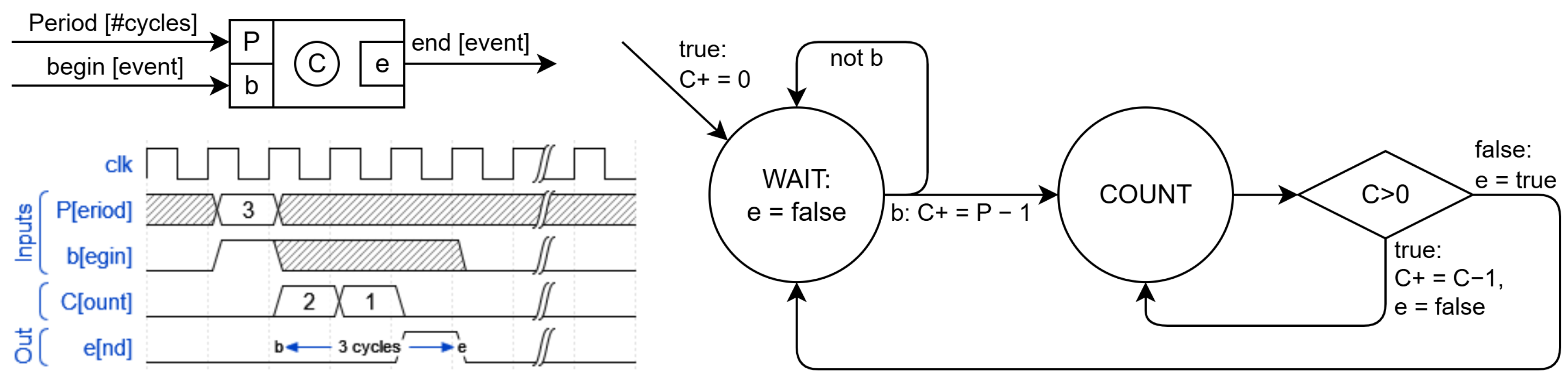
Figure 3.
Explicit hierarchical state machines (top) and simulation by communicating parallel EFSMs sharing memory (bottom).
Figure 3.
Explicit hierarchical state machines (top) and simulation by communicating parallel EFSMs sharing memory (bottom).
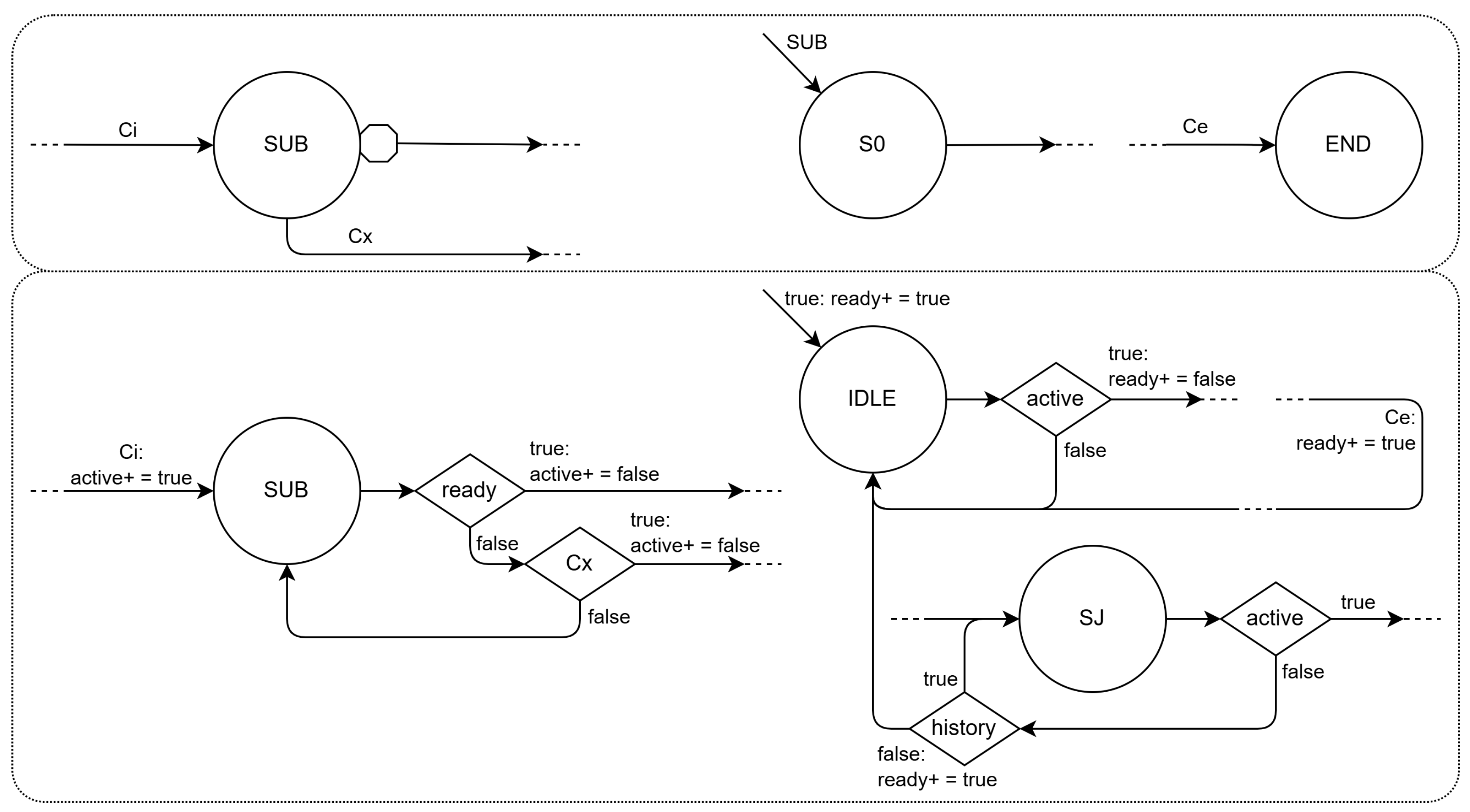
Figure 4.
EFS2Ms are EFSMs with state stacks. The smaller bubbles represent operations on the state stack: pops if they are at the beginning of an arrow and pushes if they are at the end. The hexagons mean emptying the stack at the beginning of an arrow and going to the state at the top of the stack (and doing the corresponding pop) if they are at the end.
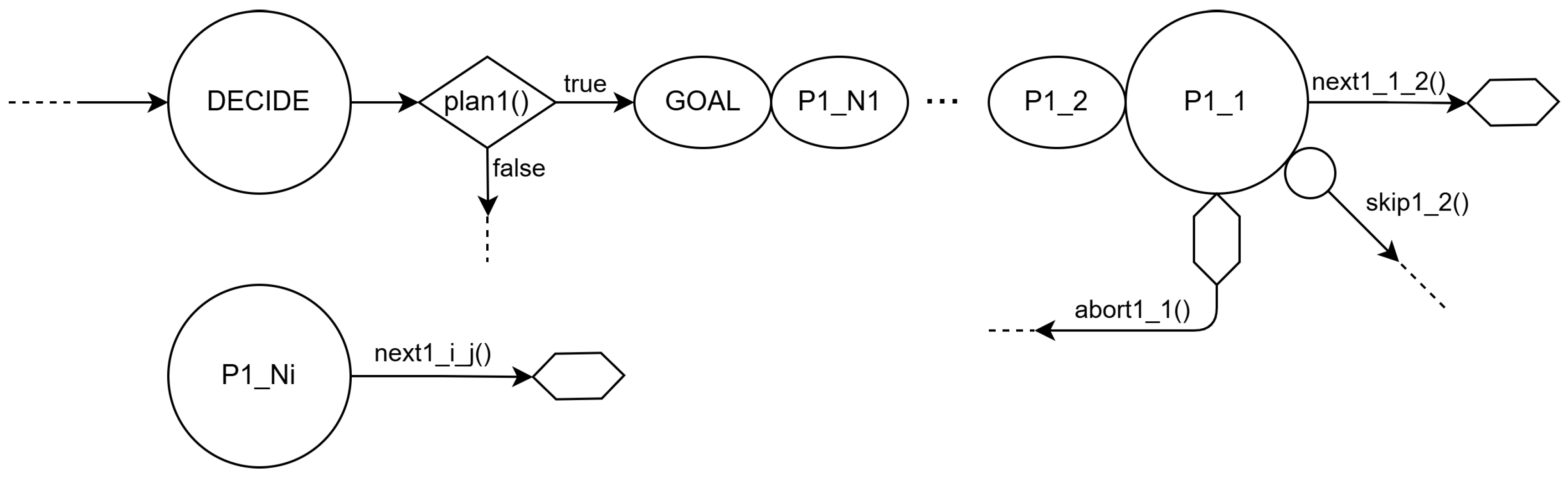
Figure 5.
The EFSM network of a controller of a mobile robot organizes in a three-tier stack.
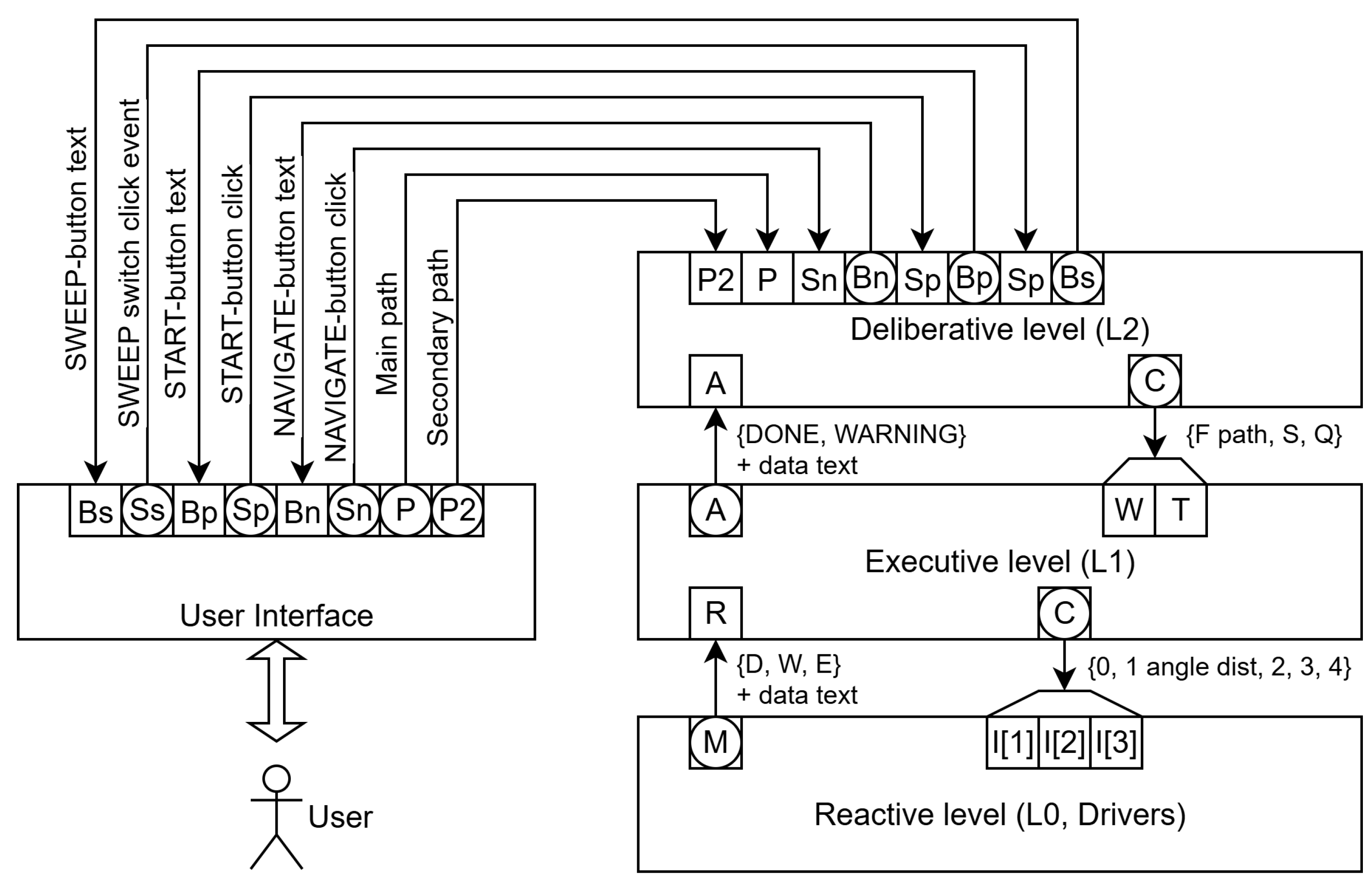
Figure 6.
Portion of the L1 EFSM that implements the LIDAR sweep procedure.
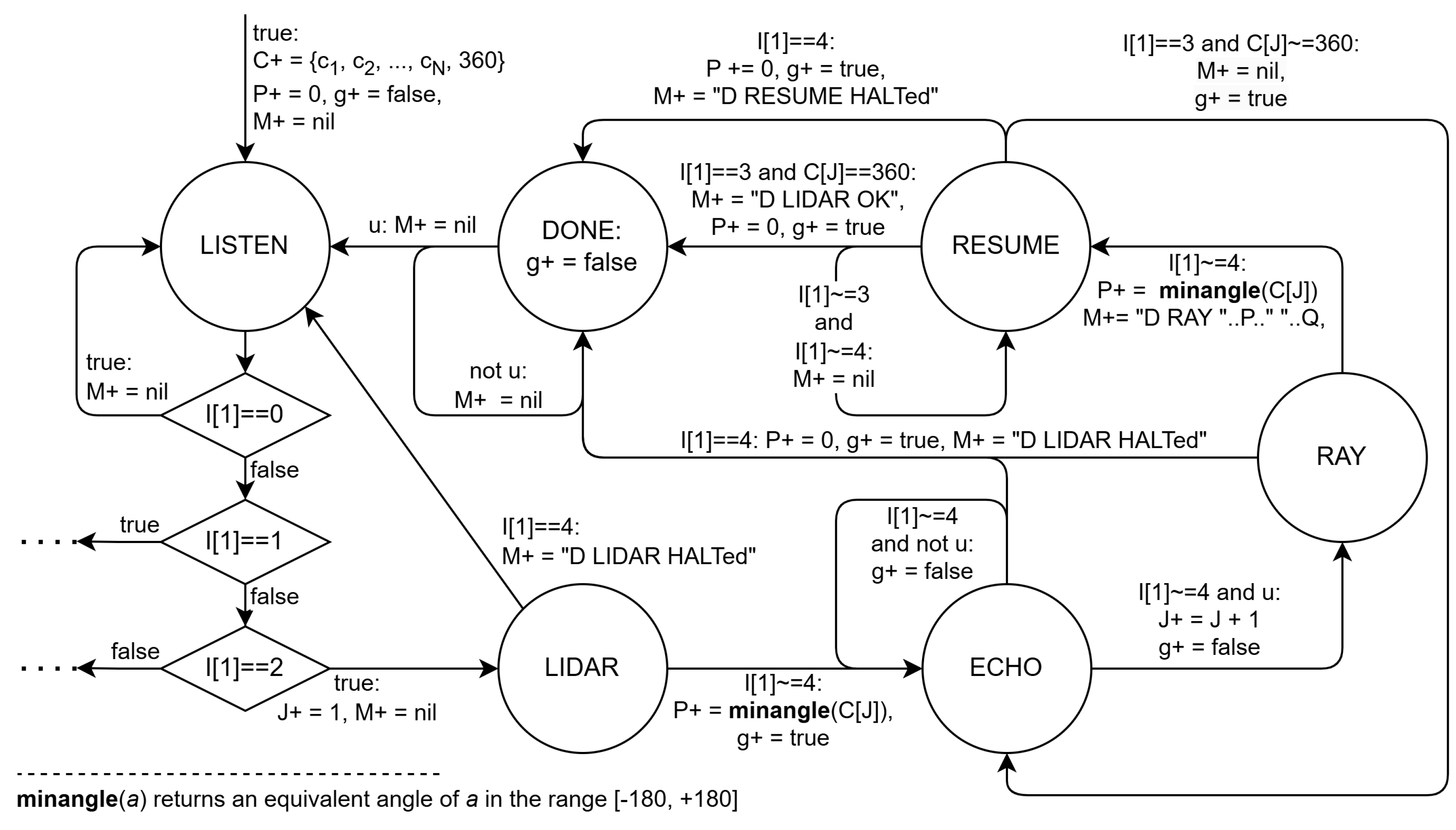
Figure 7.
The simulation of the EFSM network in real time includes a waiting state (IDLE) to synchronize the simulation time with the real time T.
Figure 7.
The simulation of the EFSM network in real time includes a waiting state (IDLE) to synchronize the simulation time with the real time T.
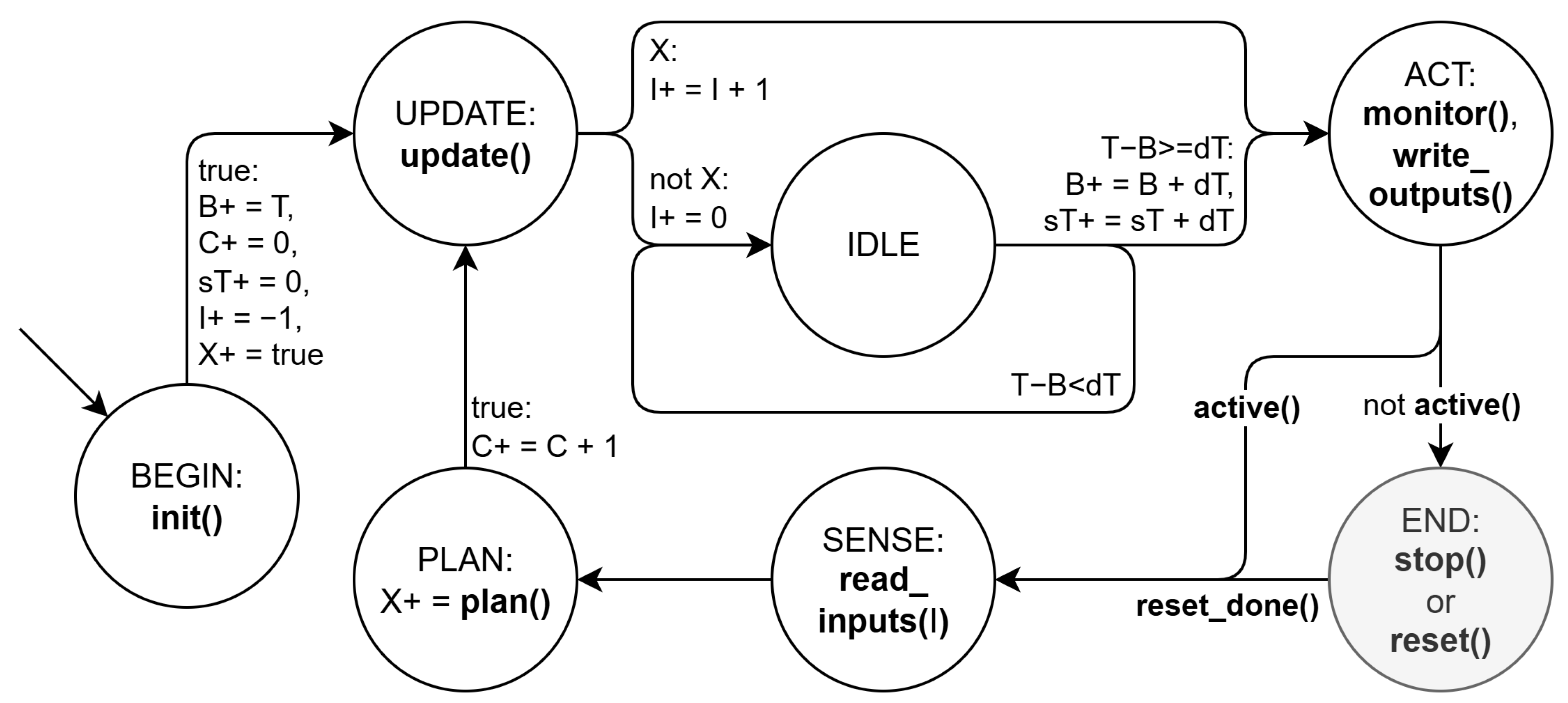
Figure 8.
The real and the virtual robot models share the higher layers of the controller and communication between these layers and the lower ones is done through the transparent layer L0L1Link, which behaves as shown in the EFSM on the left, giving priority to the real robot and counting (D) how many cycles the simulation lags behind reality.
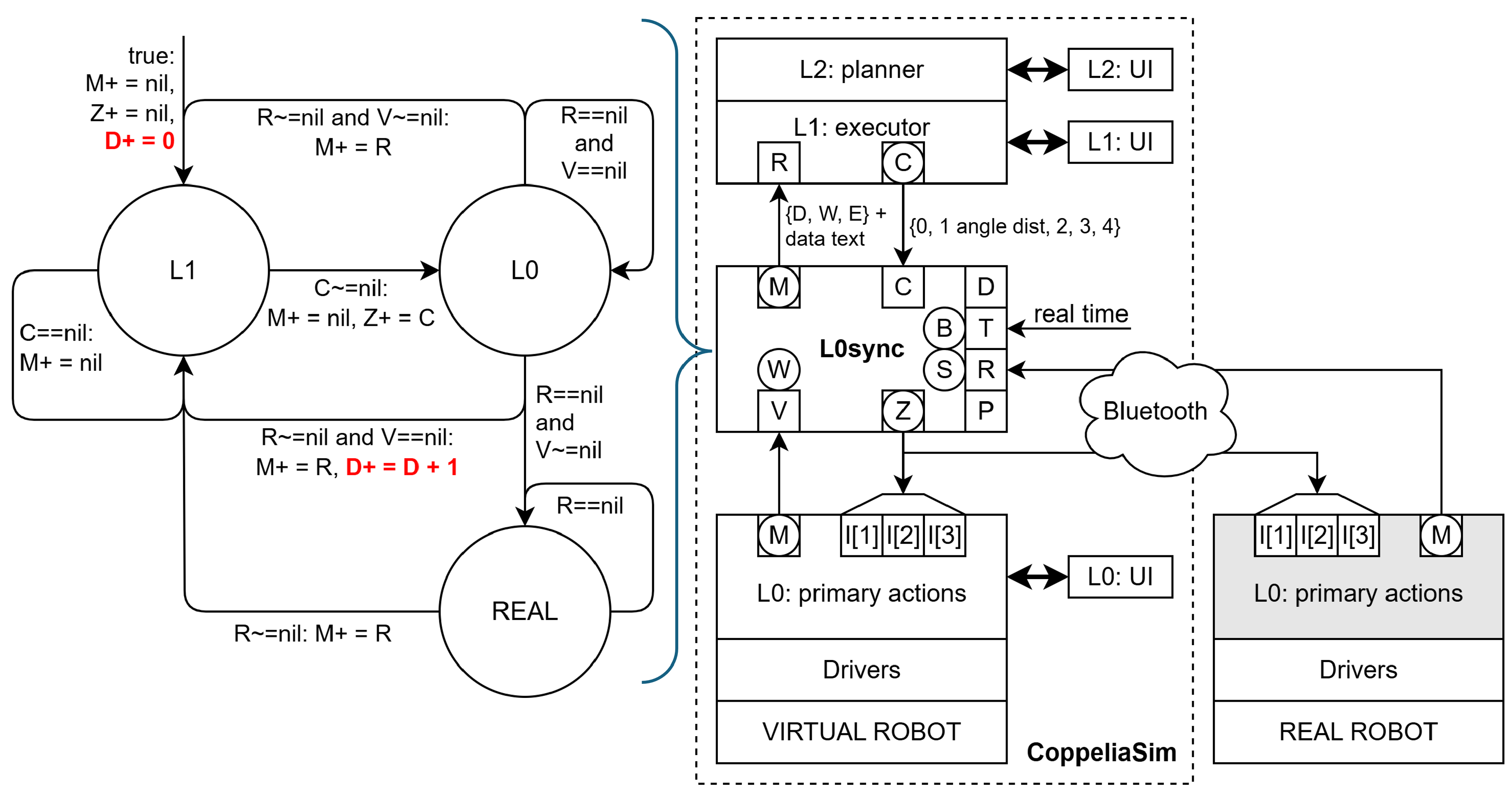
Figure 9.
The smart data logger stores filtered messages into a log file that can be further analyzed to update the robot’s high-level model and determine the causes of eventual system.
Figure 9.
The smart data logger stores filtered messages into a log file that can be further analyzed to update the robot’s high-level model and determine the causes of eventual system.
Disclaimer/Publisher’s Note: The statements, opinions and data contained in all publications are solely those of the individual author(s) and contributor(s) and not of MDPI and/or the editor(s). MDPI and/or the editor(s) disclaim responsibility for any injury to people or property resulting from any ideas, methods, instructions or products referred to in the content. |
© 2026 by the authors. Licensee MDPI, Basel, Switzerland. This article is an open access article distributed under the terms and conditions of the Creative Commons Attribution (CC BY) license (http://creativecommons.org/licenses/by/4.0/).
Copyright: This open access article is published under a Creative Commons CC BY 4.0 license, which permit the free download, distribution, and reuse, provided that the author and preprint are cited in any reuse.


