
Submitted:
18 April 2025
Posted:
21 April 2025
You are already at the latest version
Abstract
This paper presents a simulation approach for mobile robots designed to operate within networks intended for emergency response scenarios. The simulation compo-nent is part of a broader and more complex system architecture focused on enhancing communication efficiency and operational coordination within robotic networks. The study leverages virtualization and robotic simulation technologies to develop a con-trolled environment in which the behavior and coordination of mobile robots can be analyzed and validated under simulated emergency conditions. To achieve this, a vir-tual machine was configured to host a ROS2 and Gazebo-based simulation environ-ment. Custom packages were developed to enable the dynamic instantiation of mobile robots and the integration of essential sensing and control functionalities. The simula-tion process was carried out in two stages: initially, a single mobile robot was deployed and evaluated; subsequently, the configuration was extended to support a second ro-bot, enabling multi-agent interaction within the simulated environment. The proposed architecture demonstrates the potential for scalable deployment and simulation of mobile robotic units in critical scenarios. As a future direction, the authors aim to ex-tend the system by optimizing data extraction from the simulation environment and implementing ROS2 microservices to facilitate secure and efficient communication with a centralized server deployed within a Kubernetes cluster. This integration will enable real-time coordination and data exchange between simulated agents and backend services, forming the foundation for a robust, distributed robotic system tai-lored to emergency operations.
Keywords:
mobile robots
; emergency situations
; dinamic simulation
; security and encryption
; cluster bridge
1. Introduction
In the increasingly frequent context of natural disasters and emergency situations, the deployment of autonomous robotic networks is becoming a strategic priority for both research and field response. Ground and aerial mobile robots can effectively support search and rescue operations in environments that are hazardous, inaccessible, or unstable for human intervention. In this regard, recent literature emphasizes the critical role of simulation components, which enable the development and validation of control, detection, and coordination algorithms prior to field deployment.
The TRIFFID study proposes an autonomous system composed of unmanned ground and aerial vehicles, equipped with AI, designed to support first responders in critical missions, highlighting the central importance of integrated planning [1]. Similarly, the bio-inspired mechanism introduced in [2] enables rapid emergency responses within multi-robot systems, drawing on the principles of collective animal reflexes. Regarding field communication, [3] demonstrates the use of collaborative robots equipped with cellular communication capabilities in dynamic operational scenarios.
Simulation also plays a pivotal role in the development of critical protocols, such as the emergency decoupling mechanism explored in [5]. For evaluating algorithmic performance and agent collaboration, platforms like the RoboCup Rescue Simulation [6] and the Advanced Disaster Management Simulator (ADMS) [7] provide standardized and reproducible environments. Additionally, simulated evacuation models [8] contribute to anticipating human behavior, while SAR-type robots are examined in [9] through the lens of air-to-ground coordination. The study in [10] explores the application of autonomous drones in the rapid delivery of medical supplies.
Collectively, these works support the argument that advanced simulation is not merely a design tool, but a core component of distributed robotic architectures, one capable of anticipating real-world hazards, optimizing response strategies, and mitigating operational risks in real missions.
The structure of this paper is centered around the development of the simulation subcomponent for mobile robots deployed within robotic networks designed for emergency response scenarios. Section 2, Architecture and Deployment of the Mobile Robotic Network Developed for Emergency Situations, introduces the role of this simulation component within the broader robotic network, along with the process of exporting the URDF file and mesh models from the CAD environment. Section 3 presents the implementation of the ROS2-Gazebo configuration through the creation of two packages responsible for node connectivity, Xacro parsing, and robot spawning in the Gazebo simulation environment. Section 4 focuses on the dynamic simulation of a mobile robot navigating flat surfaces, while Section 5 describes the reconfiguration of the system for supporting multiple robots, with two mobile robots introduced at this testing phase. Section 6 outlines future improvements, including the creation of realistic emergency scenarios and a parallel operational model involving three mobile robots in a coordinated search and rescue mission. The paper concludes with a summary of the main findings and directions for further research.
2. Architecture and Deployment of the Mobile Robotic Network Developed for Emergency Situations
As previously mentioned, the virtualized simulation subcomponent of the robotic network architecture involves the creation of emergency response scenarios and the analysis of experimental data. The need for a simulation environment stems from its ability to generate preliminary results through the abstraction of real-world emergency resolution processes.
This subcomponent is integrated into the architecture of a mobile robotic network and connects to its central server via a secure TLS communication protocol, implemented in the form of a ROS Bridge. Figure 1 illustrates the bidirectional link between the robotic network server—deployed within a Kubernetes cluster and simulated using Minikube—and a Hyper-V virtual machine that runs the simulation environment associated with the simulation subcomponent. The Hyper-V virtualization platform was selected to host a virtual machine running Ubuntu 22.04 LTS. Within this environment, ROS2 Humble and the Gazebo Ignition simulation framework have been installed and configured. Data exchanged between the virtual machine and the robotic network server is transmitted through ROS2 nodes and topics.
Figure 1 also outlines the broader system architecture, which will be developed in a subsequent research phase. The proposed design leverages Kubernetes-based infrastructure and partitions the network’s components into three distinct security zones: OT (Operational Technology), DMZ (Demilitarized Zone), and IT (Information Technology). Each of these zones hosts critical elements of the robotic network, including the central server, the web platform, and the relational database management system (RDBMS). Furthermore, a Read-Only application is proposed for deployment within the DMZ security zone. The IT zone will be limited to handling user authentication and registration processes, abstracted via web-based applications.
This study focuses on the installation and configuration of the Robot Operating System (ROS) environment alongside the Gazebo simulation framework. In addition, the authors propose the simulation of a locomotion scenario on flat surfaces. The data extracted from the simulation will be transmitted to the Minikube cluster via the WSS protocol, secured using TLS encryption.
The first step in developing the simulation component involves exporting the meshes and the URDF file for the network's mobile robots from the CAD environment. The authors have designed a mobile robot model intended for emergency scenarios, employing a hybrid leg-wheel locomotion system, as illustrated in Figure 2 [11]. This model was developed following an in-depth review of the specialized literature on locomotion systems for mobile robots in emergency response contexts, as documented in the second research report of the doctoral thesis [15].
The export process involves several steps that establish the connection between the CAD environment and the information management framework in ROS, specifically the Unified Robot Description Format (URDF). Exporting the URDF model using the URDF Exporter plugin from SolidWorks provides a raw representation of the robot structure. Consequently, this file must be refined and optimized through the use of Xacro syntax. Section 2.1 details the methodology for exporting and optimizing the data in ROS-compatible format.
The export process requires the definition of the robot’s subassemblies (links) and the connections (joints) between them, followed by the specification of the kinematic coupling types. For the proposed mobile robot, all couplings between geometric elements are fifth-class rotational joints, as illustrated in Figure 3 [11].
The export process involves defining the mobile robot’s subassemblies (links) and the joints connecting them, followed by the specification of the kinematic coupling types. For the proposed mobile robot, all couplings between geometric elements are classified as fifth-class rotational joints.
To simplify the initial simulation of the mobile robot, seven standalone subassemblies were defined, as presented in Table 1 [11].
The next step involves the actual export of the model and the creation of configuration files for the ROS2 operating system. These files implicitly include the XML-based URDF file of the mobile robot.
The URDF Export plugin uses the coordinate systems assigned to each component, starting from the base element (base_link), which were manually defined within the CAD environment.
Model properties can be modified either directly within the plugin or subsequently, after the XML file has been generated.
Exporting the meshes in STL format for use in the simulation requires preprocessing and proper alignment relative to their respective 3D coordinate systems. Figure 5 [11] a), b), c), and d) illustrate the geometry of all components of the mobile robot. The MeshLab software was used for manipulating the subassemblies and correctly centering them within the workspace.
Based on these two components, the URDF file and the mobile robot’s mesh model the robot can be abstracted and integrated into the ROS2 and Gazebo simulation environment. The following section focuses on the configuration of the simulation environment.
3. Architecture and Deployment of the Simulation Subcomponent
To install and configure the ROS2 operating system and the Gazebo simulation environment, Hyper-V—a Windows-integrated virtualization platform—was used to create virtual machines. As such, a virtual machine was created to host the installation of Ubuntu 22.04 LTS.
In order to dynamically simulate the mobile robot, beyond the initial configuration, additional functionalities are required to link the URDF file publication to the /robot_description topic and to the Gazebo environment. To achieve this, two ROS2 packages were created, each responsible for one of the two core functionalities:
- my_robot_description – .for publishing the URDF file to the corresponding topic and launching it within the Gazebo environment;
- my_robot_bringup – for spawning the mobile robot;
- (a)
- my_robot_description package
This package is structured around multiple configuration files that read, install, and launch the functionalities required to transmit URDF data to the Gazebo environment, as illustrated in Figure 6 [11].
The /meshes folder contains the subassemblies exported from SolidWorks, which serve as link elements within the Gazebo environment.
The /urdf folder stores the robot’s structural information in an optimized format. The remaining files are responsible for launching and configuring RViz, URDF, and mesh resources for data transmission to the /robot_state_publisher topic.
- (b)
- my_robot_bringup package
This package is responsible for spawning the mobile robot within the Gazebo environment by interfacing ROS2 with the ros_gazebo plugin. The first step involves launching Gazebo in basic factory mode, followed by linking the /robot_state_publisher topic to the simulator. Gazebo acts as a subscriber to this topic and receives continuous updates regarding the robot’s position, as illustrated in Figure 7 [11].
These packages will transmit and receive information via ROS nodes in order to enable dynamic simulation within the Gazebo environment. Subsequently, the URDF file—extracted from the SolidWorks CAD environment—will be processed using Xacro syntax, and additional functionalities will be configured to enable robot motion.
Dynamic simulation in Gazebo requires modifying the URDF file using Xacro syntax and incorporating information related to mass and inertia by defining the inertia tensor, along with collision-related properties. Accordingly, Figure 8 [11] presents and abstracts the base link of the mobile robot through three key components: visual elements (visual), collision elements (collision), and inertial elements (inertial), which encode data on mass and mechanical moments of inertia.
The remaining components of the mobile robot were modeled using the same set of properties.
Regarding the joints of the mobile structure, these are defined using the standard Xacro block, as shown in Figure 9 [11], where their position, orientation, and type are specified. Some joints also include abstracted mechanical constraints.
This information is retrieved from the Xacro file by the /my_robot_description package and published to the /robot_description topic, from where it is subsequently propagated to the /rosout topic. This allows the data to reach the /gazebo node, where the /my_robot_bringup package uses the spawn function to instantiate the mobile robot within the simulation environment. This informational flow is illustrated in Figure 10 [11].
Additionally, Figure 10 also defines the control of the mobile robot’s DC motors through the use of the /cmd_vel and /odom topics. Within these two topics, the /diff_drive_controller node publishes control and feedback data, and it is defined in the Xacro file shown in Figure 11 [11].
This controller is configured for the front wheels of the mobile robot. Similarly, a separate controller will be configured for the rear wheels. Once these nodes and topics have been properly set up, the mobile robot was spawned in the Gazebo environment by executing a launch file that instantiates all associated functionalities. The resulting simulation of the mobile robot can be observed in Figure 12 [11].
The selected environment serves as a test model for evaluating locomotion on flat surfaces. Gazebo provides various functionalities for visualizing coordinate frames of the structural links, visual geometry, collision boundaries, inertial properties, and mass distribution. These aspects are illustrated in Figure 13 [11] a), b), c), d), e), and f), and are extracted from the Xacro file.
For the testing phase, a virtual sensor was also added to the Xacro configuration, an RGB camera mounted at the front of the mobile robot, as shown in Figure 14 [11].
This component will retrieve audio-video data from the simulation environment and publish it to the /camera_sensor topic, as shown in Figure 15 [11].
Its configuration requires the definition of several data structures, including the configuration section shown in Figure 16 [11].
This plugin utilized the /libgazebo_ros_camera.so library. The images captured by the AV camera can be transmitted through the topic it publishes to and redirected to the robotic network server via the WSS protocol for display within the WebPlatform. The testing phase for the AV camera functionality involved using the images published to the /camera_sensor topic, which were then subscribed to and visualized in RViz2 (the static simulation environment in ROS2), as shown in Figure 17 [11].
In conclusion, these functionalities can be further extended through the development of ROS–Gazebo microservices and the creation of a structured information flow within the system. The following section presents the dynamic Gazebo simulation of a mobile robot within the test environment.
4. Dinamic Simulation of One Mobile Robot Using Flat Surfaces
Dynamic simulation requires the use of a simulation environment, referred to as a world. For the testing phase, a simulation environment was selected that includes a surface and several elements resembling those typically found in a room. These elements were positioned in a disordered, overturned manner to simulate an emergency scenario, such as an earthquake or a fire-damaged area.
The ROS2 and Gazebo configuration described in the previous section was used. This configuration is launched via a launch file named /display.launch.xml, developed within the /my_robot_description package. Its purpose is to instantiate all communication and simulation components of the proposed architecture.
As a result, the mobile robot model was successfully transmitted and instantiated in the Gazebo simulation environment without errors, based on the system log output shown in Figure 18 [11].
The system is controlled entirely through the Ubuntu terminal, using a Bash shell to interact with the virtual kernel elements. The log summary confirms the successful parsing of the Xacro file elements, their publication within the Gazebo environment, and the acceptance of the virtual control configuration for the DC motors.
To print the velocities of the DC motors, Vectors 3 and 5 must be configured—corresponding to the linear and angular vectors, respectively—as shown in Figure 19 [11]. For the testing phase, data was published to the /odom topic using the /geometry_msgs/msg/Twist interface. In ROS2, this vector is generically referred to as Twist.
The linear velocity will be published in the Vector3 subvector of the Twist vector, with a value of 0.4 m/s, as shown in Figure 20 [11].
Thus, the mobile robot will move within the workspace at the velocity published to the /cmd_vel topic by transmitting the Twist vector using the /geometry_msgs/msg/Twist interface. Figure 21 [11] a) and b) show two positions of the mobile robot following its linear movement along the x-axis.
Additionally, a graph was extracted showing the position, linear velocity, and linear acceleration of the mobile robot along the x-axis, as presented in Figure 22 [11]. The simulation was conducted over a duration of 13 seconds.
These values were extracted by the /odom topic interogation.
Section 5 presents a method for connecting two mobile robots within the Gazebo simulation environment.
5. Connecting Two Mobile Robots in the Gazebo Simulation Environment
The Gazebo simulation environment allows for the spawning of multiple entities, in this case mobile robots, by modifying the system configuration. Accordingly, the ROS packages and launch files were adapted to support the deployment of two identical mobile robots, with the communication architecture illustrated in Figure 23 [11]. This configuration, visualized using rqt_graph, displays the ROS package nodes specific to each mobile robot instance, /robot1 and /robot2, which publish and receive information from both Gazebo topics and the AV camera topic.
Thus, after instantiating all necessary packages via two launch files, the mobile robots were successfully spawned in the Gazebo simulation environment, as shown in Figure 24 [11].
The authors aim to extend these functionalities by testing various simulation environments, such as a dedicated search and rescue scenario. Due to the high computational load of the virtual machine, mainly caused by the simulation of realistic robot collisions, only two mobile robot entities were instantiated during the current phase.
The Future Work section proposes increasing the processing power of the virtual machine and introducing ROS2-orchestrated microservices to enable a fully networked operational model. This functionality will allow mobile robots to collaborate with one another and to transmit data both within the ROS2 environment and toward the Minikube cluster.
6. Future Work
The proposed activities for the further development of the simulation environment focus on two key stages related to the integration of this component into a networked architecture.
The first stage involves expanding the virtual machine by allocating additional resources, enabling the integration of multiple mobile robots within the simulation environment. Additionally, the authors aim to develop ROS2 microservices to manage the data exchanged via nodes and topics in an automated manner, ensuring its transmission to the Minikube cluster, specifically to the server pod of the robotic network. For this information to be processed by the network server, a secure and encrypted connection is required. To this end, a ROS Bridge will be used to connect the Hyper-V virtual machine to the network server. The authors propose a WSS model secured with TLS encryption and the use of HTTPS requests for data exchange. Furthermore, an alternative communication node based on the gRPC protocol is proposed, intended for mobile robots with higher processing capabilities that can support such libraries.
The second stage of development involves designing emergency scenarios using specialized simulation environments and proposing communication strategies. An initial network operation model is presented in Table 2, simulating the phases of a search and rescue mission involving three mobile robots, two ground-based and one aerial.
Bazat pe acest mod de lucru, se vor dezvolta microservicii care să integreze aceste funcționalități de bază ale unei misiuni de urgență, pentru căutare și salvare.
7. Conclusions
In conclusion, this work focused on the development of the simulation subcomponent of the robotic network through the implementation of ROS2 and Gazebo technologies. This subcomponent is part of a much more complex system that will be further developed using Kubernetes orchestration technologies.
Emergency scenario simulation is essential, as it enables foresight and anticipation of the complex events typically encountered in such situations. For this reason, it is of significant interest to leverage simulation as much as possible, both for training the robotic system and for preparing the human personnel involved. This approach helps reduce the risk of injury to personnel assisting in field missions.
Based on this perspective, the development of such networked robotic systems—equipped with integrated simulation capabilities—is both justified and of great relevance. The scientific literature reflects this trend and presents various configurations that integrate and simulate mobile robots within distributed networks. These configurations require continuous research and optimization, as emergency situations are highly dynamic and subject to constant change.
Abbreviations
The following abbreviations are used in this manuscript:
| ADMS | Advanced Disaster Management Simulator |
| API | Application Programming Interface |
| AV | Audio-Video |
| CAD | Computer Aided Design |
| DC | Direct Current |
| DMZ | Demilitarized Zone |
| HTTPS | Sercure Hyper Transfer Protocol |
| Hyper-V | Hypervisor - Virtualization |
| IT | Information Technology |
| K8S | Kubernetes |
| LTS | Long Term Support |
| OT | Operational Technology |
| RDBMS | Relational Database Management System |
| ROS | Robot Operation System |
| STL | STereoLithography |
| TLS | Transport Layer Security |
| TRIFFID | auTonomous Robotic aId For increasing First responDers efficiency |
| URDF | Unified Robot Description Format |
| VM | Virtual Machine |
| WSS | Web Socket Secure |
| XML | eXtensible Markup Language |
| Xacro | XML Macros |
| gRPC | google Remote Procedure Call |
| mTLS | Mutual TLS |
References
- Idrees, M.; et al. TRIFFID: Autonomous Robotic Aid For Increasing First Responders Efficiency. *arXiv* 2024. arXiv:2502.09379.
- Yuan, J.; et al. Collective Conditioned Reflex: A Bio-Inspired Fast Emergency Reaction Mechanism for Designing Safe Multi-Robot Systems. *arXiv* 2022. arXiv:2202.11932.
- Asenov, I.; et al. Cellular-enabled Collaborative Robots Planning and Operations for Search-and-Rescue Scenarios. *arXiv* 2024. arXiv:2403.09177.
- Kim, S.; et al. HEROES: Unreal Engine-based Human and Emergency Robot Operation Education System. *arXiv* 2023. arXiv:2309.14508.
- Ramos, G.; et al. Developing an Emergency Robotic Undocking Protocol Using Simulation. *Robotics and Autonomous Systems* 2021, *140*, 103757. [CrossRef]
- Kitano, H.; Tadokoro, S.; et al. RoboCup Rescue: Search and Rescue in Large-Scale Disasters as a Domain for Multi-Agent Research. In *Proceedings of the IEEE Conference on Systems, Man, and Cybernetics*, Tokyo, Japan, 1999; pp. 739–743.
- ADMS. Advanced Disaster Management Simulator. Available online: https://en.wikipedia.org/wiki/Advanced_disaster_management_simulator (accessed on 17 April 2025).
- Pan, X.; Han, C.S.; Dauber, K.; Law, K.H. Human and Social Behavior in Computational Modeling and Analysis of Egress. *Automation in Construction* 2006, *15*(4), 448–461. [CrossRef]
- Murphy, R.R.; et al. Search and Rescue Robotics. In *Springer Handbook of Robotics*, 2nd ed.; Siciliano, B.; Khatib, O., Eds.; Springer: Cham, Switzerland, 2016; pp. 1201–1222. [CrossRef]
- Rosser, J.C.; Vignesh, V.; Terwilliger, B.A.; Parker, B.C. The Medical Application of Drones: A Literature Review. *Surgical Innovation* 2018, *25*(5), 521–527. [CrossRef]
- Mărieș, M.; Studies and Research on the Operation and Integration of Mobile Robots into Emergency Networks. Scientific Research Report III, Doctoral School of UTCN, Faculty of Road Vehicles, Mechatronics and Mechanics, Department of Mechatronics and Machine Dynamics, Cluj-Napoca, Romania, 2025. Supervizor Professor Tătar, M.O.
- ROS2 Documentation. Available online: https://docs.ros.org/en/humble/index.html (accessed on 08.12.2024).
- Node.js APIs. Available online: https://nodejs.org/docs/latest/api/ (accessed on 08.12.2024).
- Gazebo Sim. Available online: https://gazebosim.org/home (accessed on 08.12.2024).
- Mărieș, M.; Locomotion Studies and Research on Mobile Robots for Emergency Situations. Scientific Research Report II, Doctoral School of UTCN, Faculty of Road Vehicles, Mechatronics and Mechanics, Department of Mechatronics and Machine Dynamics, Cluj-Napoca, Romania, 2024. Supervizor Professor Tătar, M.O.
- Arduino Official Site: Available online https://app.arduino.cc/sketches?custom_banner=cloud_banner (accessed on 08.12.2024).
Figure 1.
High-Level Structural Overview of the bridge between Kubernetes cluster and Simulation Environment.
Figure 1.
High-Level Structural Overview of the bridge between Kubernetes cluster and Simulation Environment.
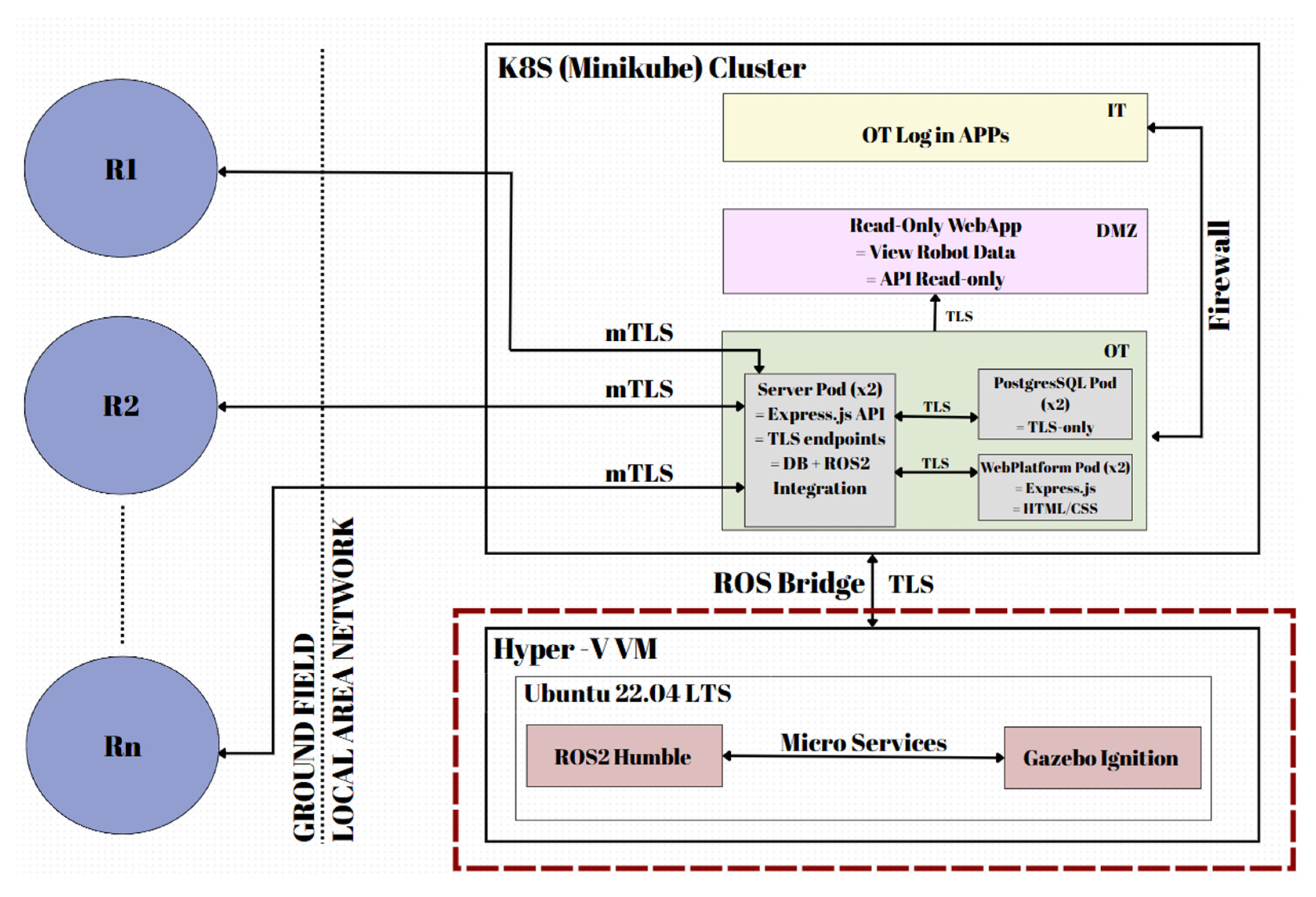
Figure 2.
The 3D model of the mobile robot equipped with a leg-wheel locomotion unit, proposed for simulation.
Figure 2.
The 3D model of the mobile robot equipped with a leg-wheel locomotion unit, proposed for simulation.
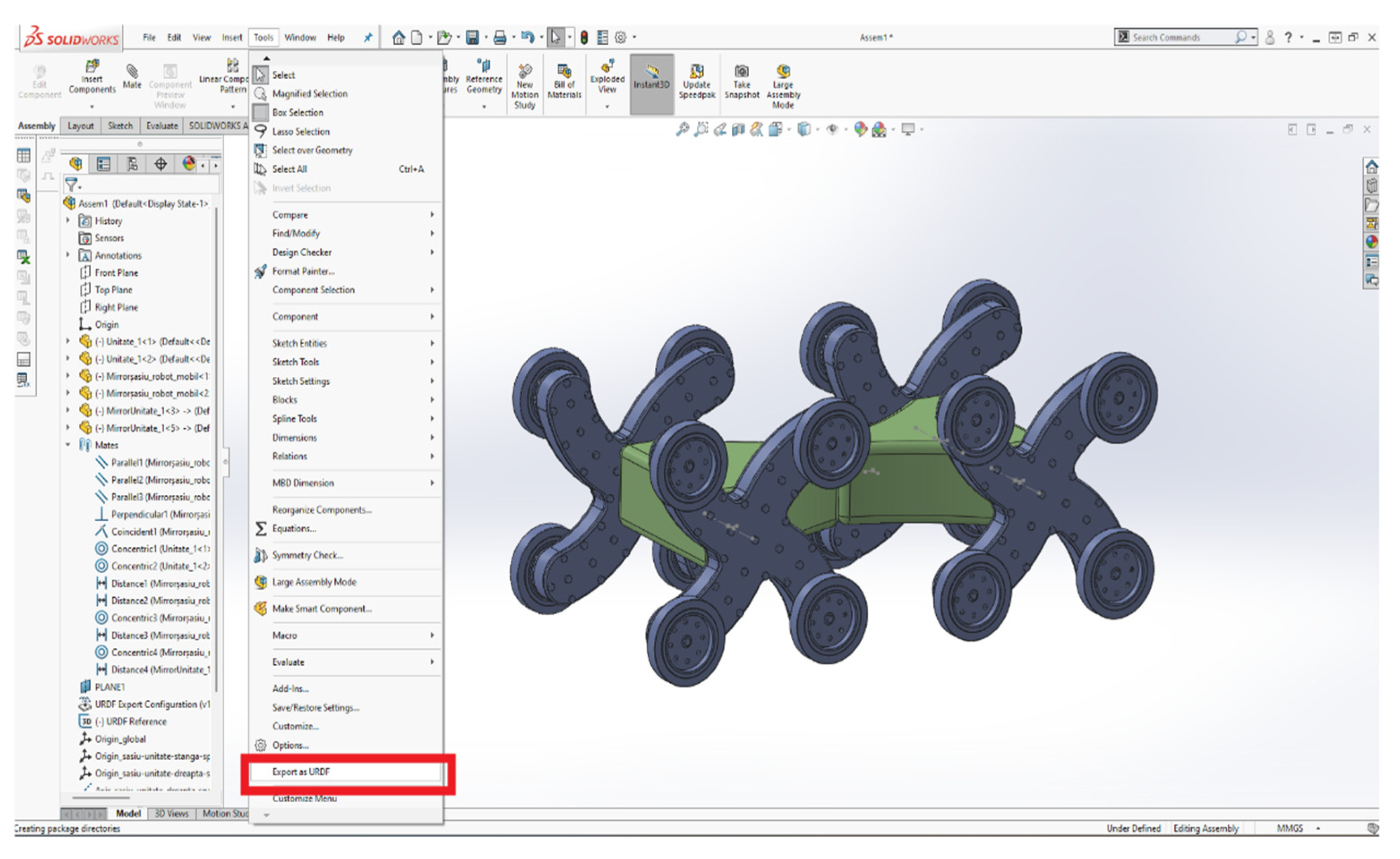
Figure 3.
Numbering of the mobile robot’s subassemblies required for URDF export.
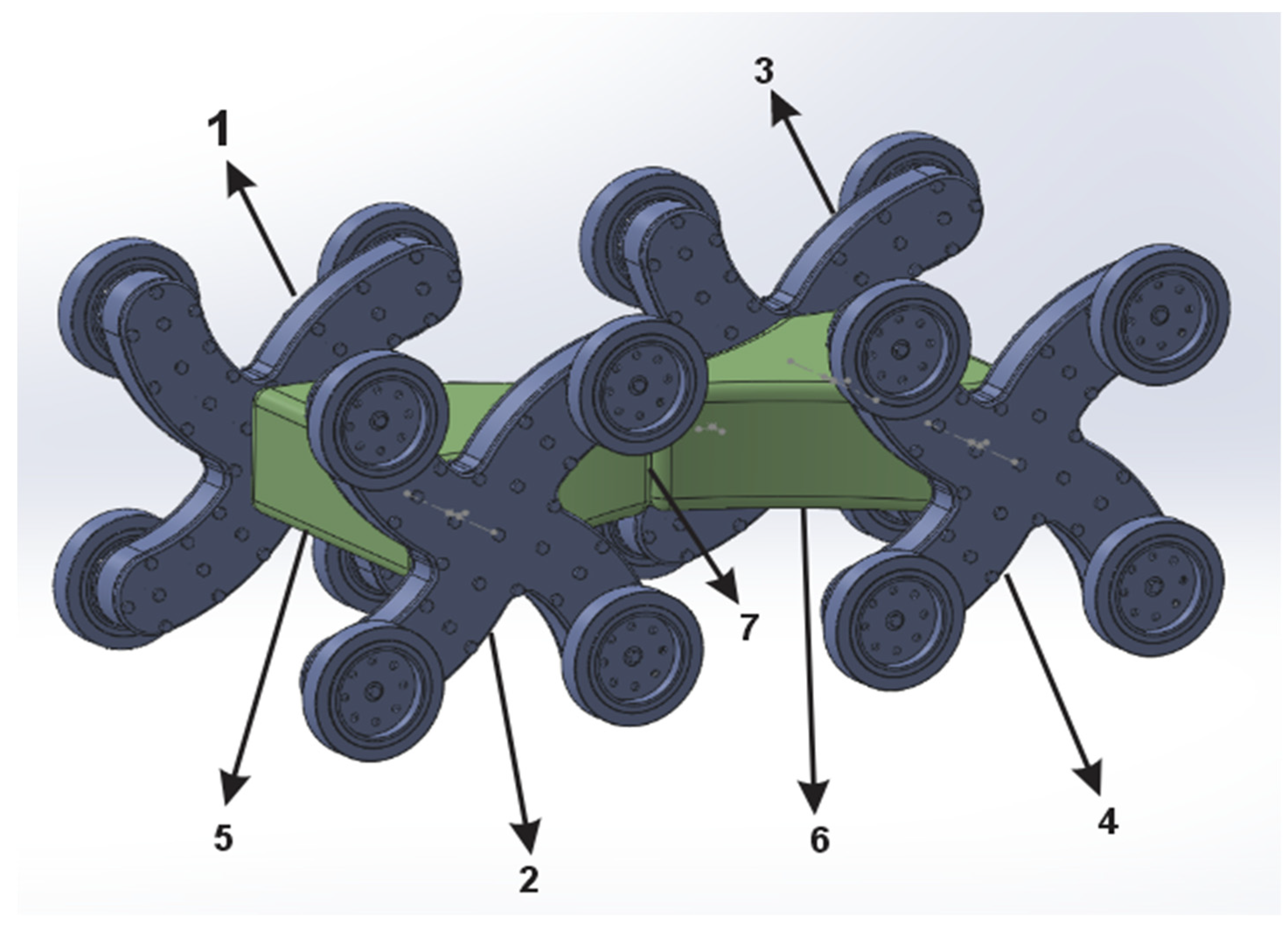
Figure 4.
Links of the 3D Model of the Mobile Robot.
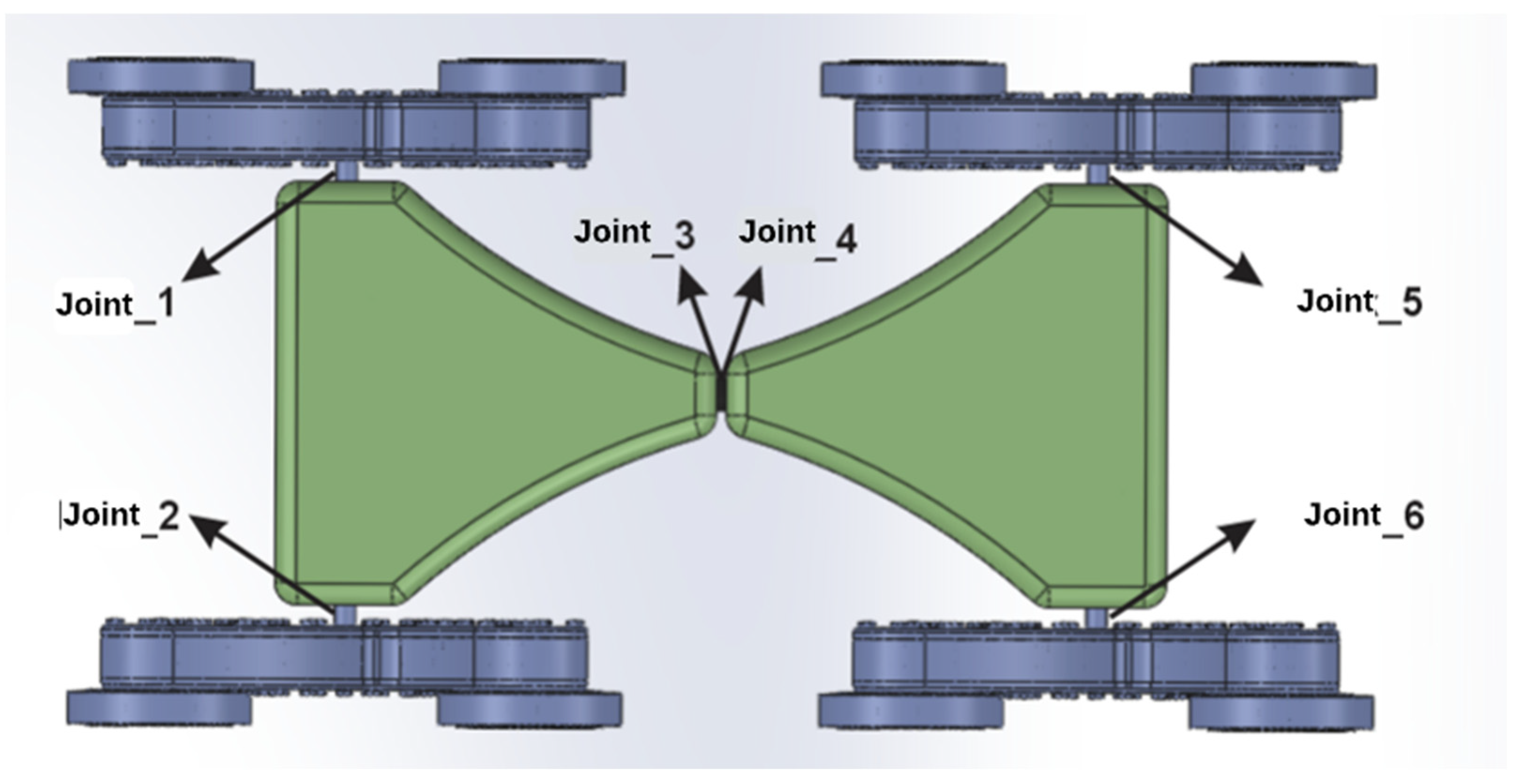
Figure 5.
Mobile robot meshes.
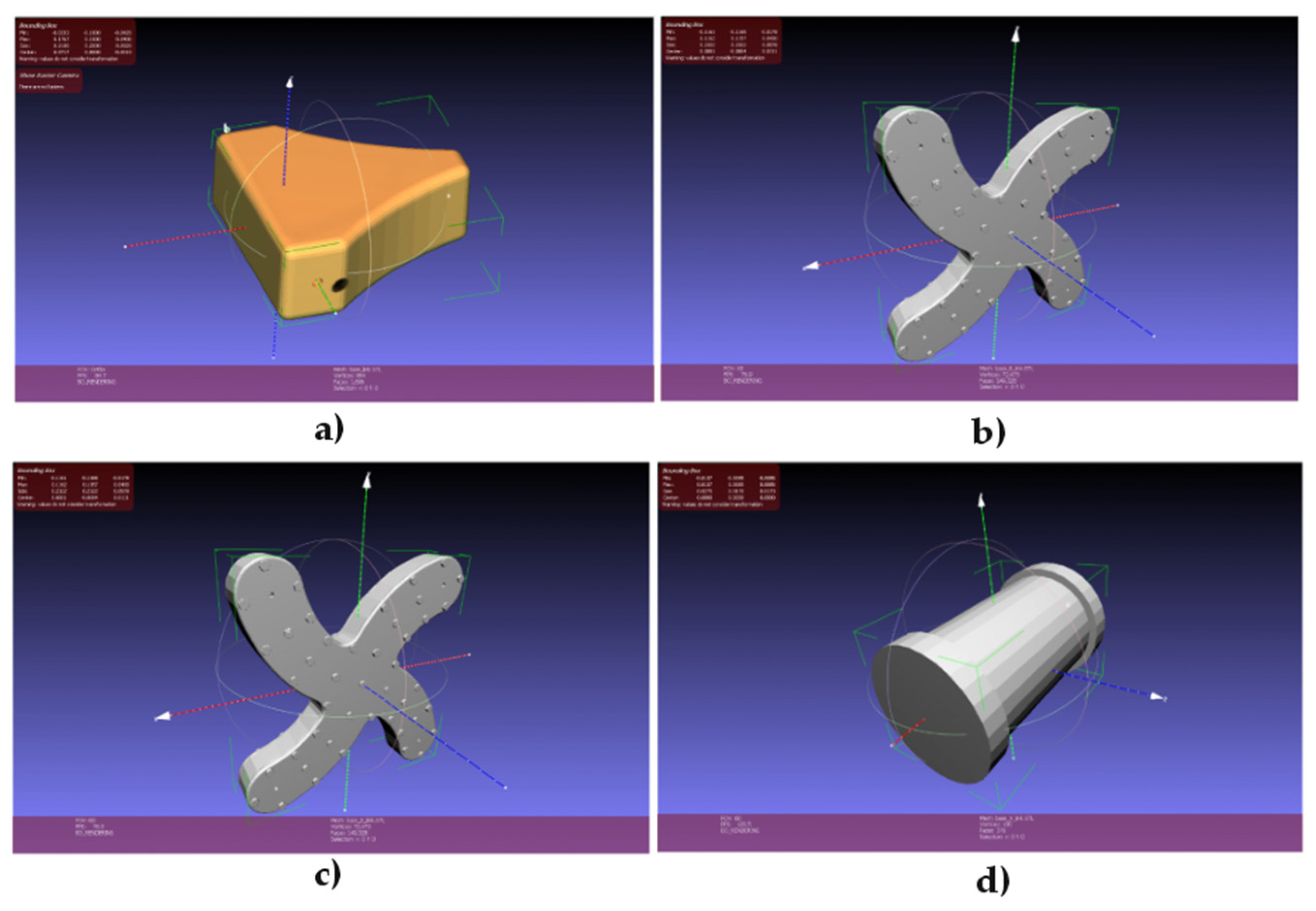
Figure 6.
Structure of /my_robot_description package.
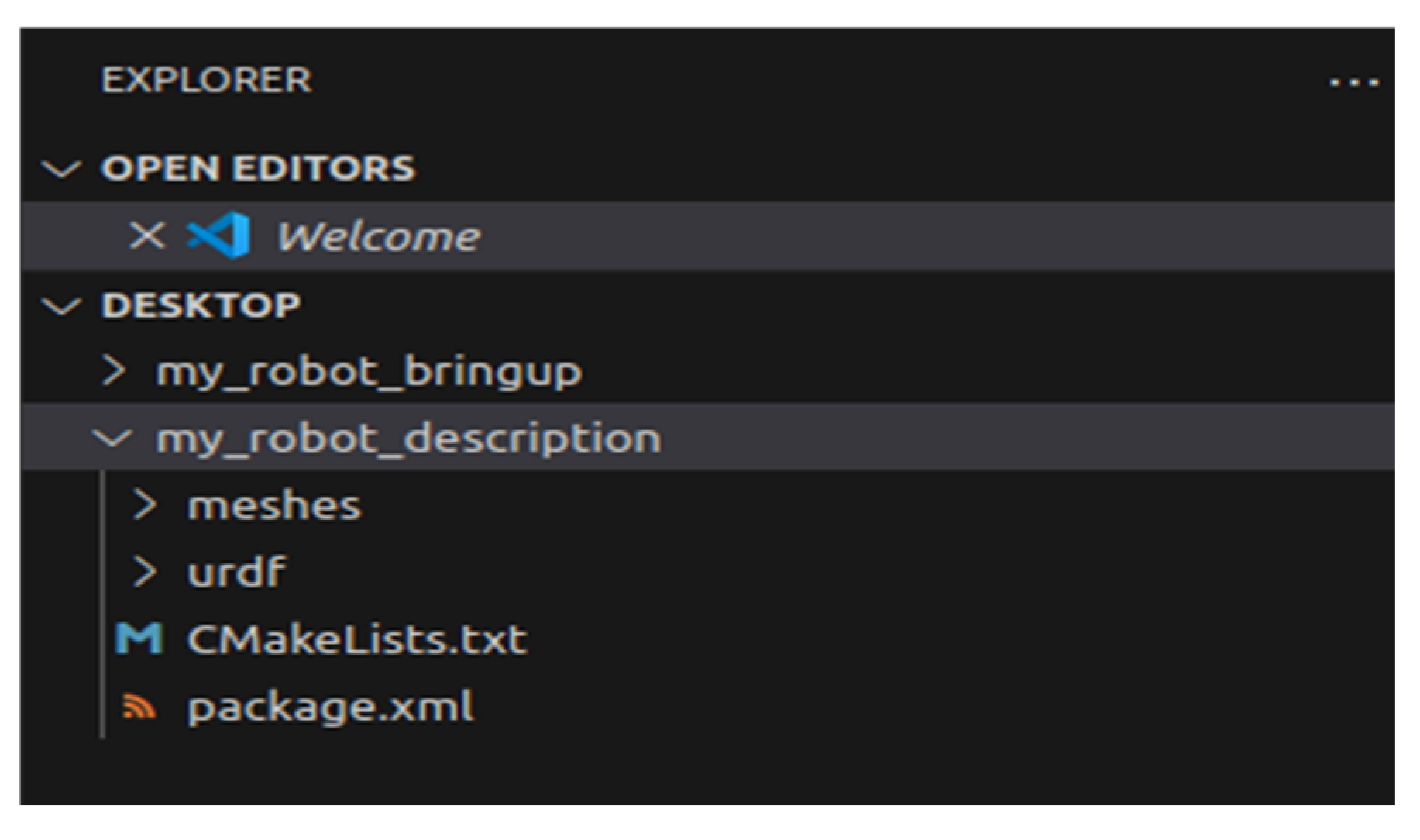
Figure 7.
Structure of /my_robot_bringup package.
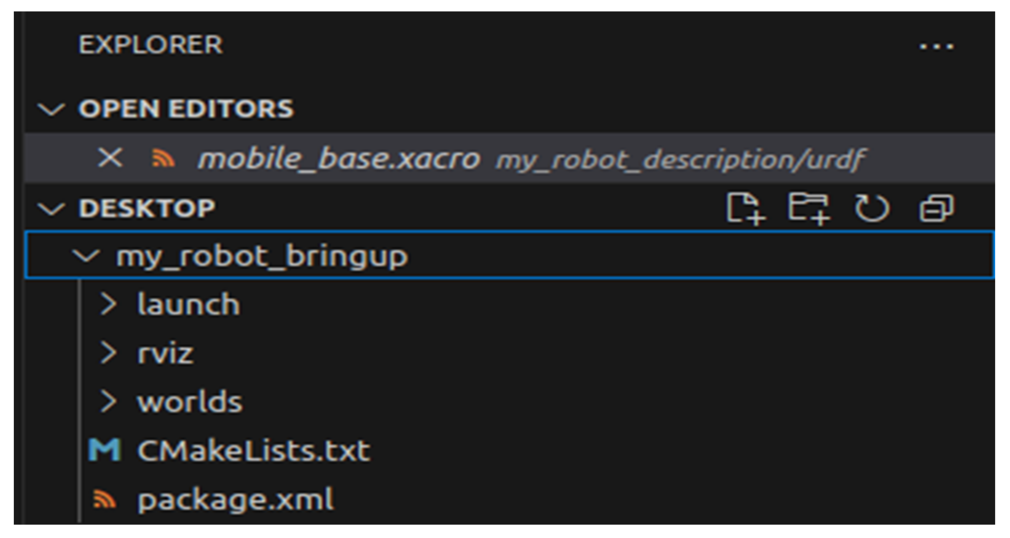
Figure 8.
Base Link Elements of the Mobile Robot in Xacro Syntax.
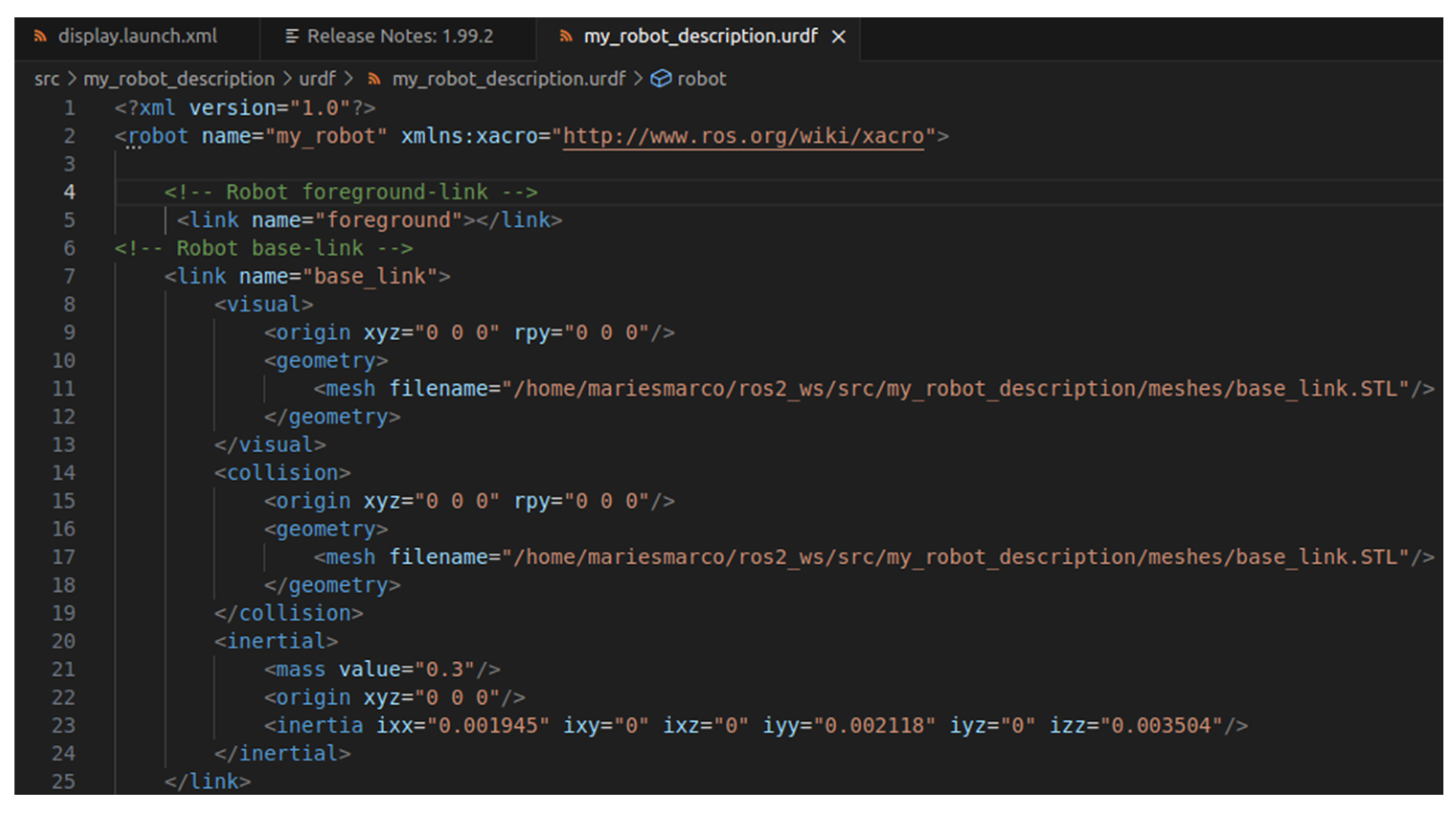
Figure 9.
Joints Elements of the Mobile Robot in Xacro Syntax.
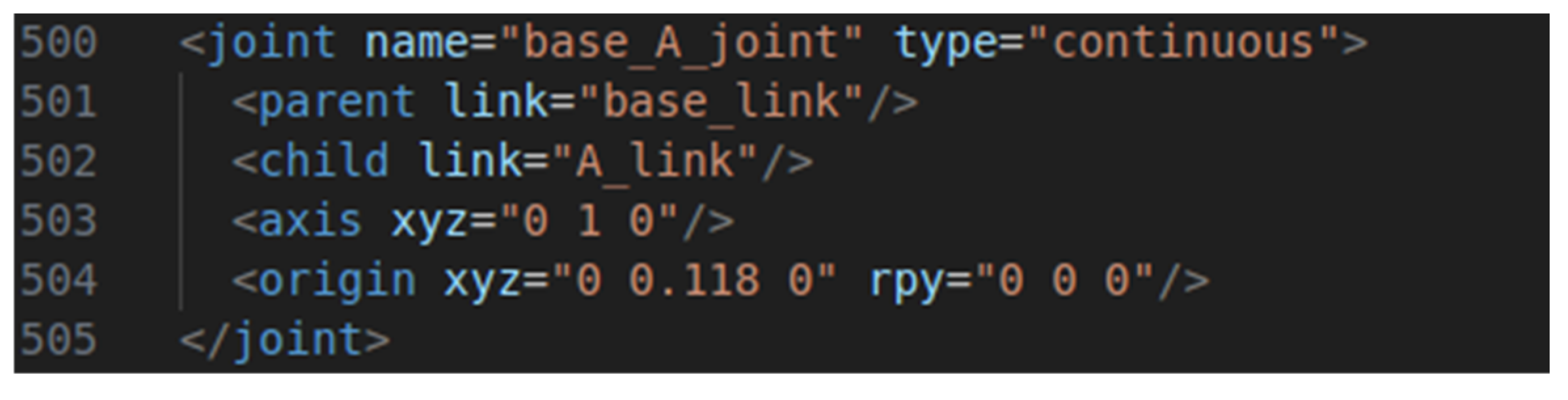
Figure 10.
Gazebo simulation communicationarchitecture.
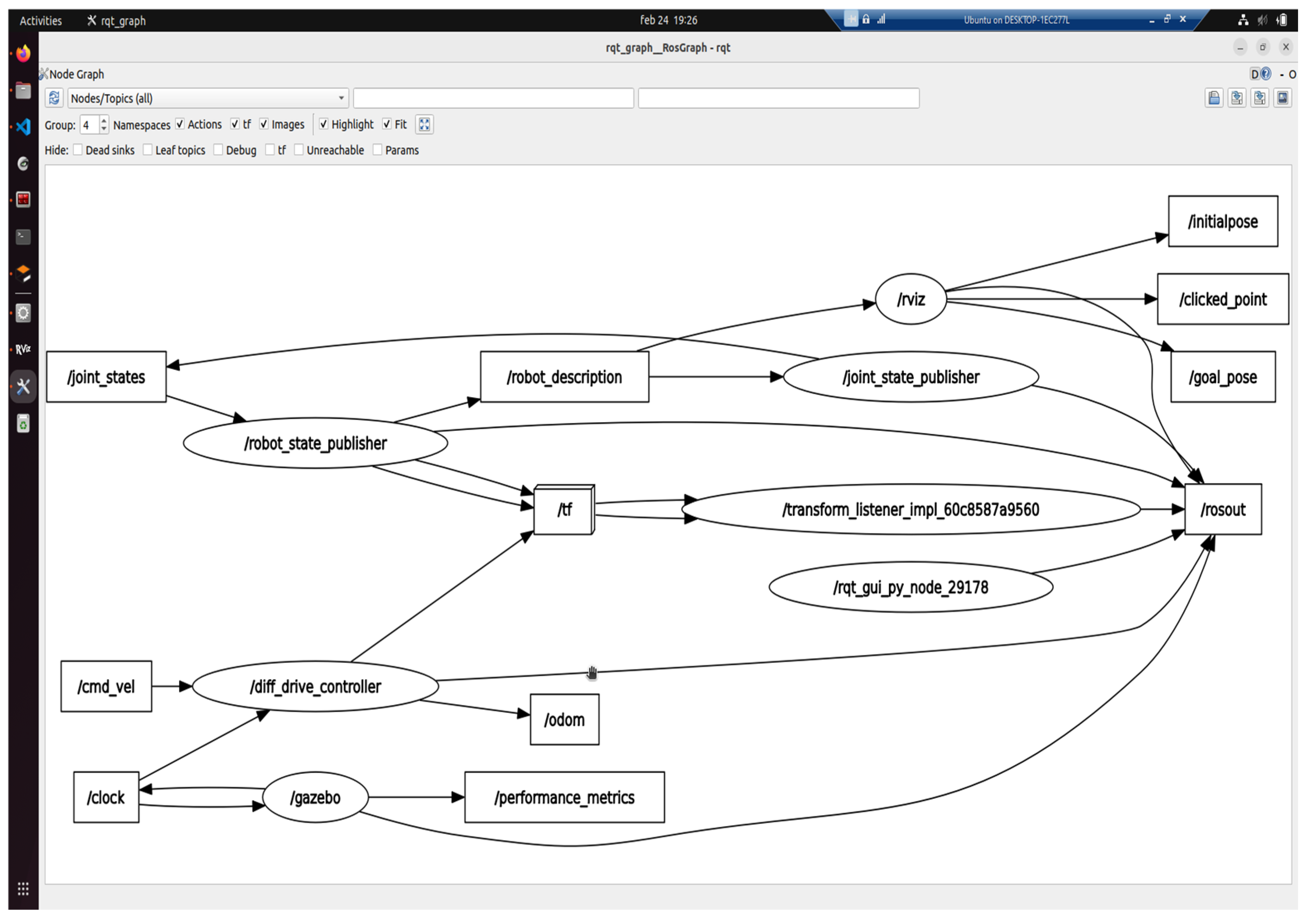
Figure 11.
Configuration of /diff_drive_controller driver.
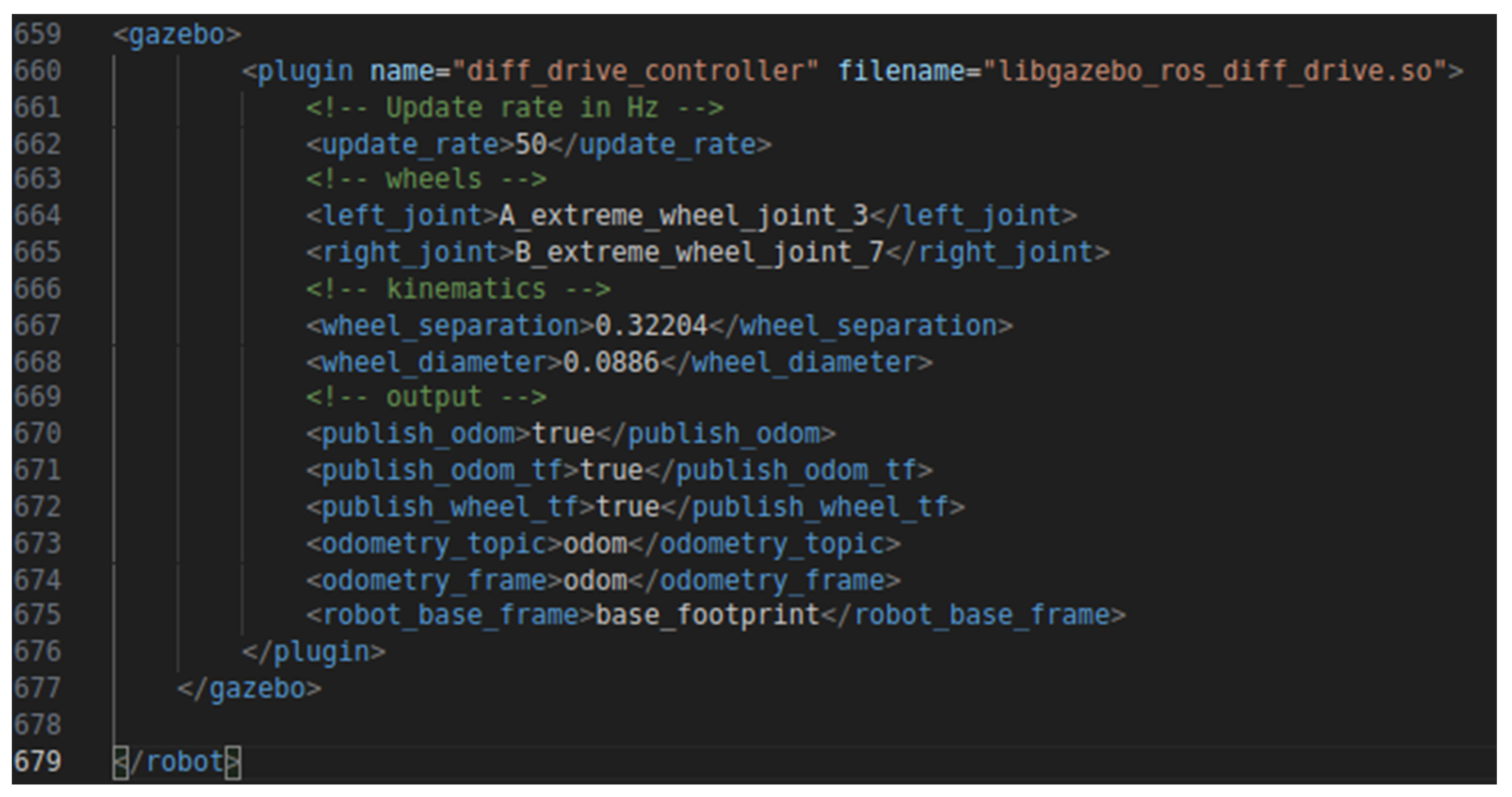
Figure 12.
Spawning of the mobile robot in Gazebo simulation environment.
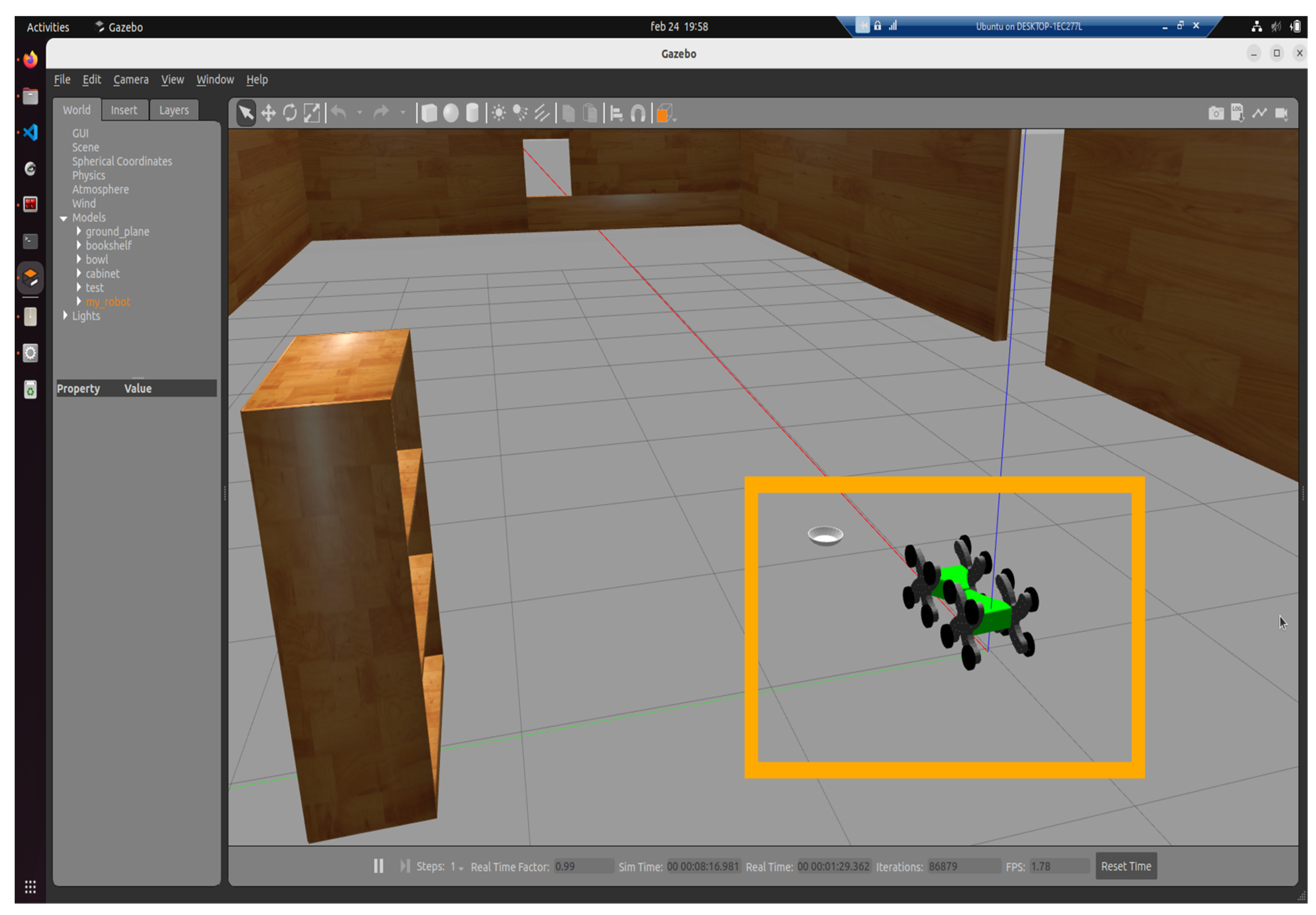
Figure 13.
Xacro information visualization in Gazebo.
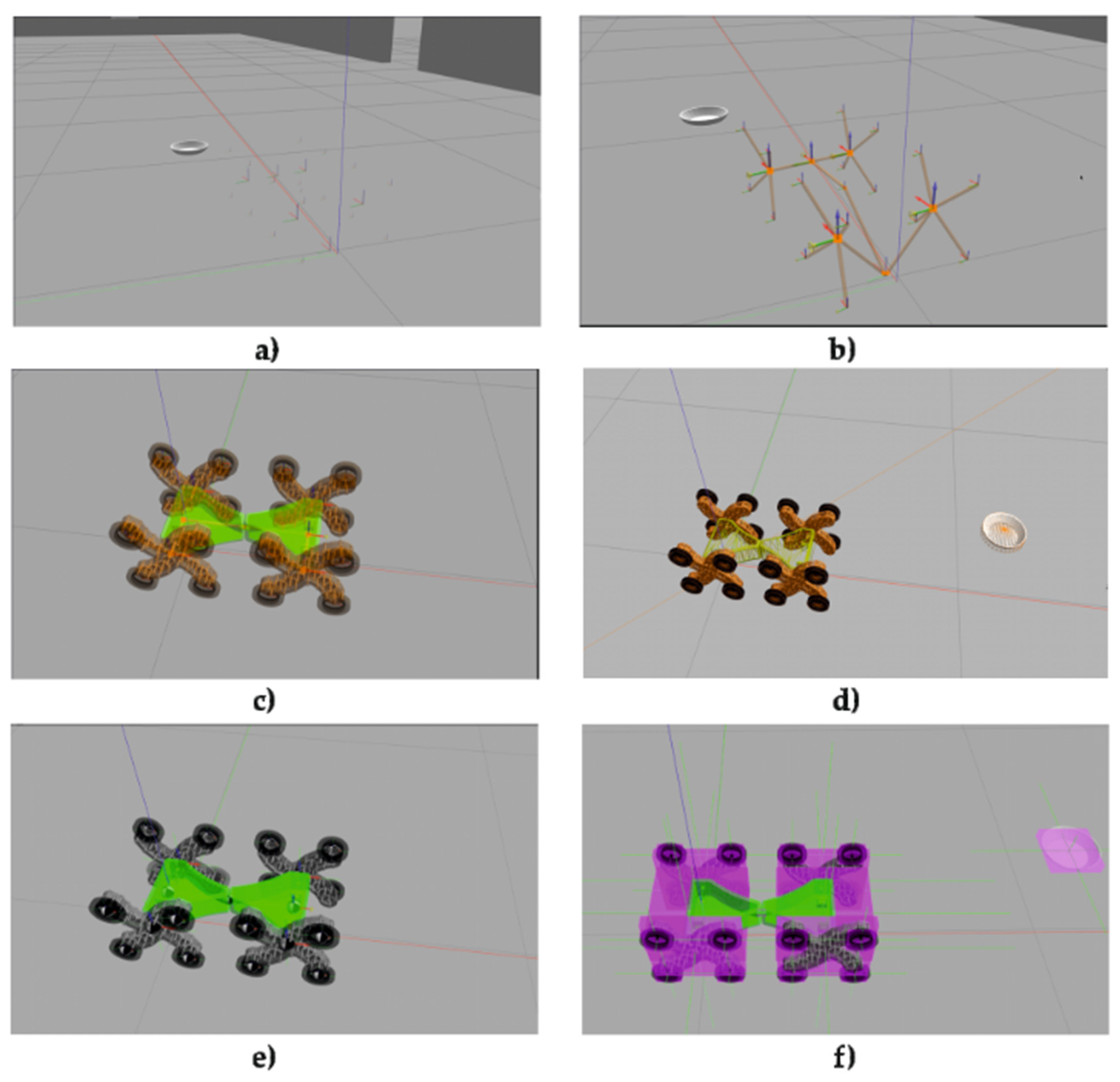
Figure 14.
Camera function.
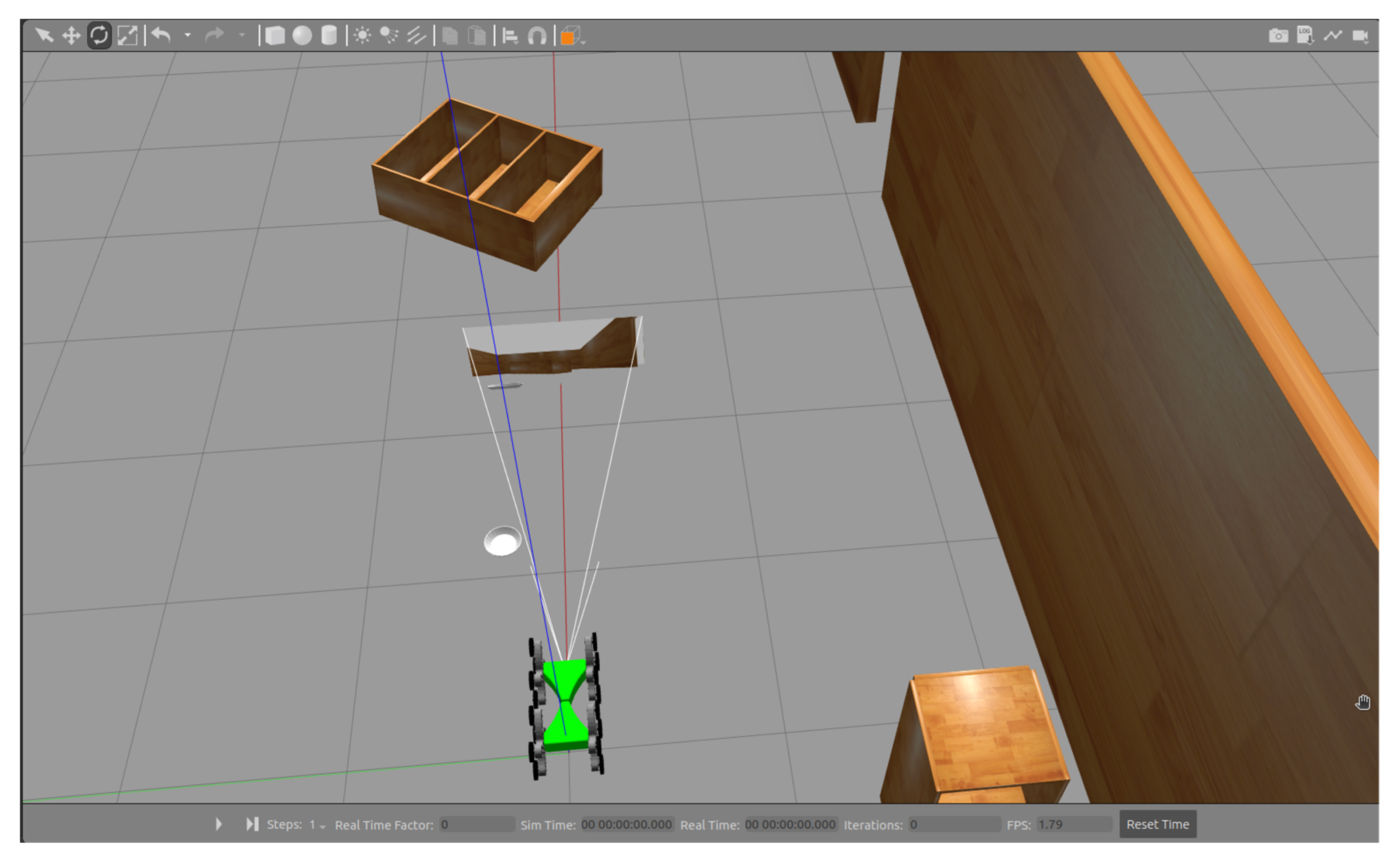
Figure 15.
Publishing AV Camera Data to the /camera_sensor Topic by the /camera_controller Node.

Figure 16.
AV Camera configuration.
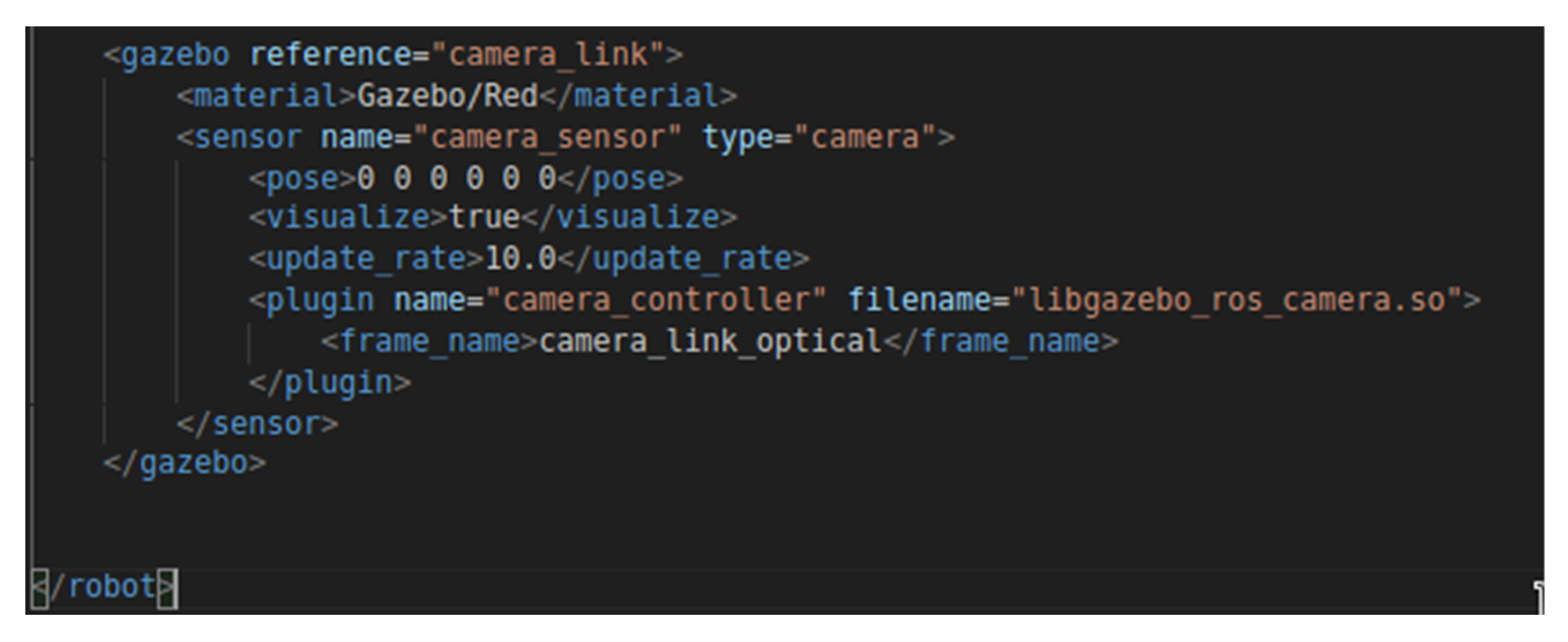
Figure 17.
Transmission of AV Camera Images to RViz2 via Topic Publishing.
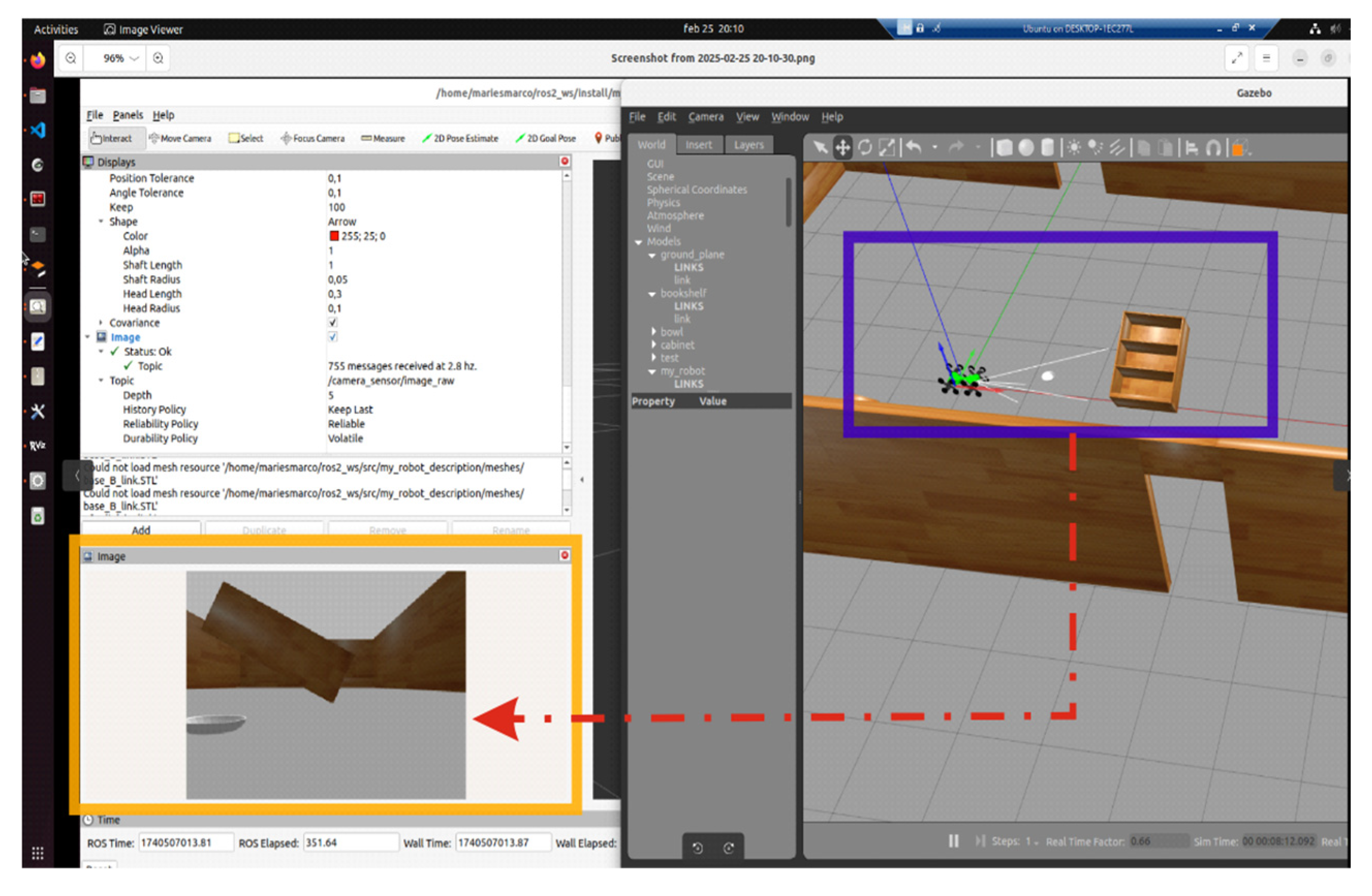
Figure 18.
Gazebo-ROS2 logs summary.
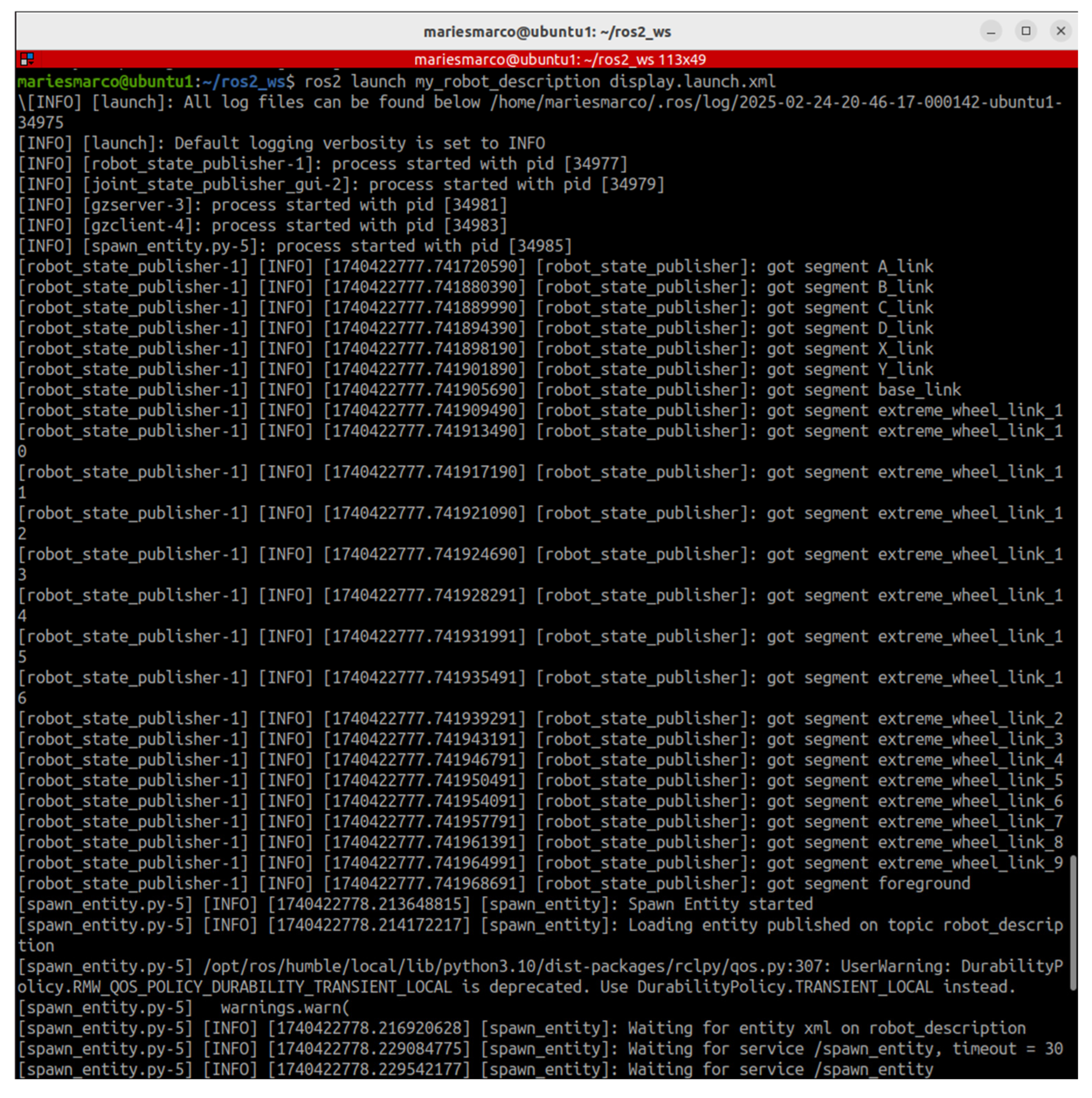
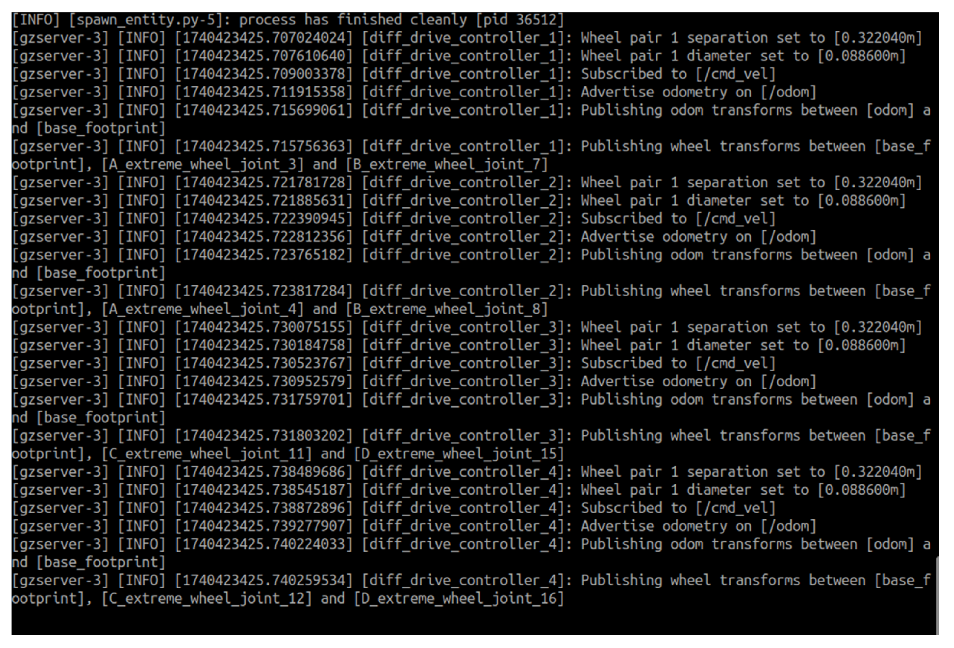
Figure 19.
Configuration of the Twist Vector and Its Subvectors Vector3 and Vector5.
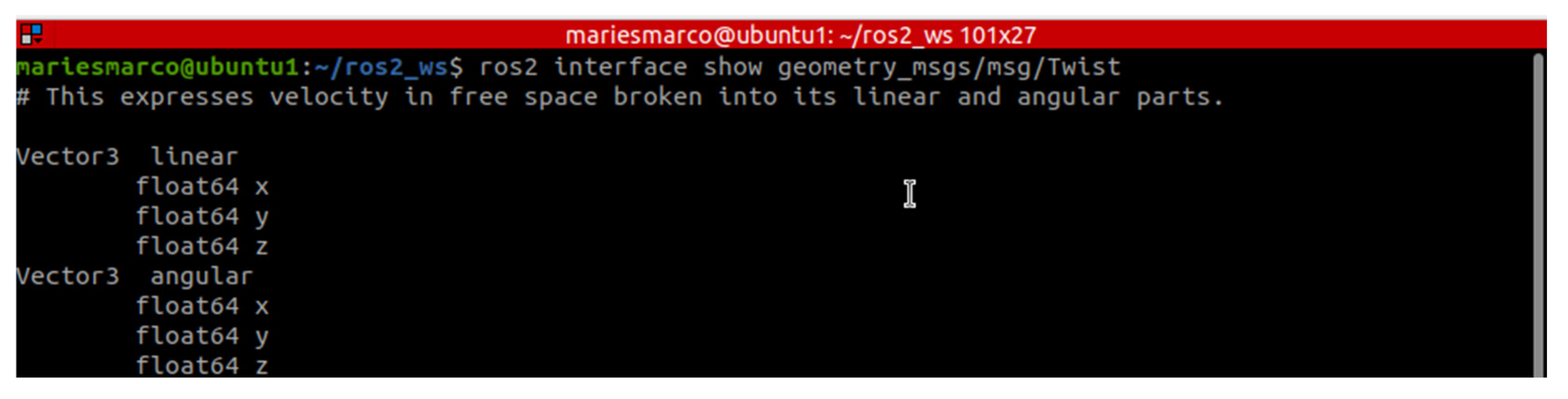
Figure 20.
Publishing the Test Velocity in the Vector3 Subvector.
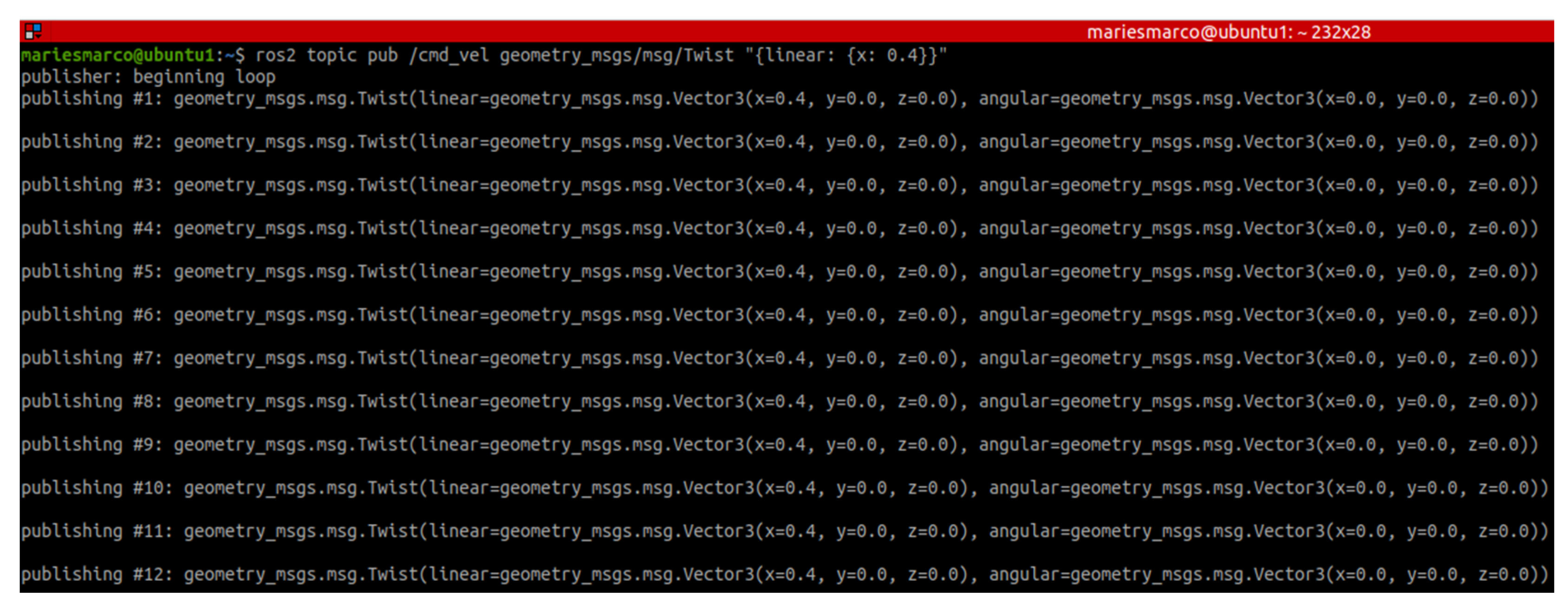
Figure 21.
X-Axis Movement of the Mobile Robot via Linear Velocity Publishing to the /odom Topic Using the /geometry_msgs/msg/Twist Interface.
Figure 21.
X-Axis Movement of the Mobile Robot via Linear Velocity Publishing to the /odom Topic Using the /geometry_msgs/msg/Twist Interface.
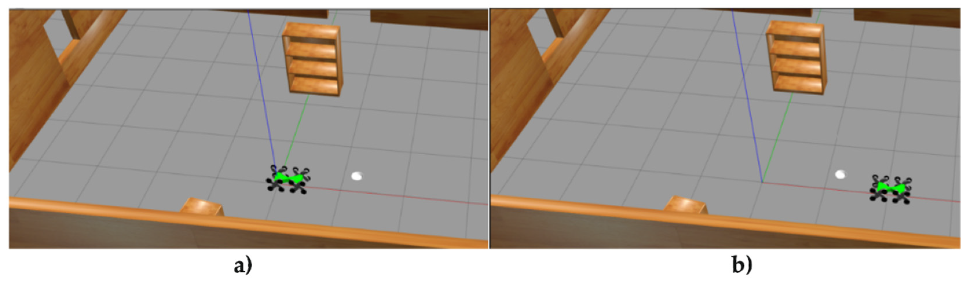
Figure 22.
Graph of the Mobile Robot’s Position, Velocity, and Acceleration.
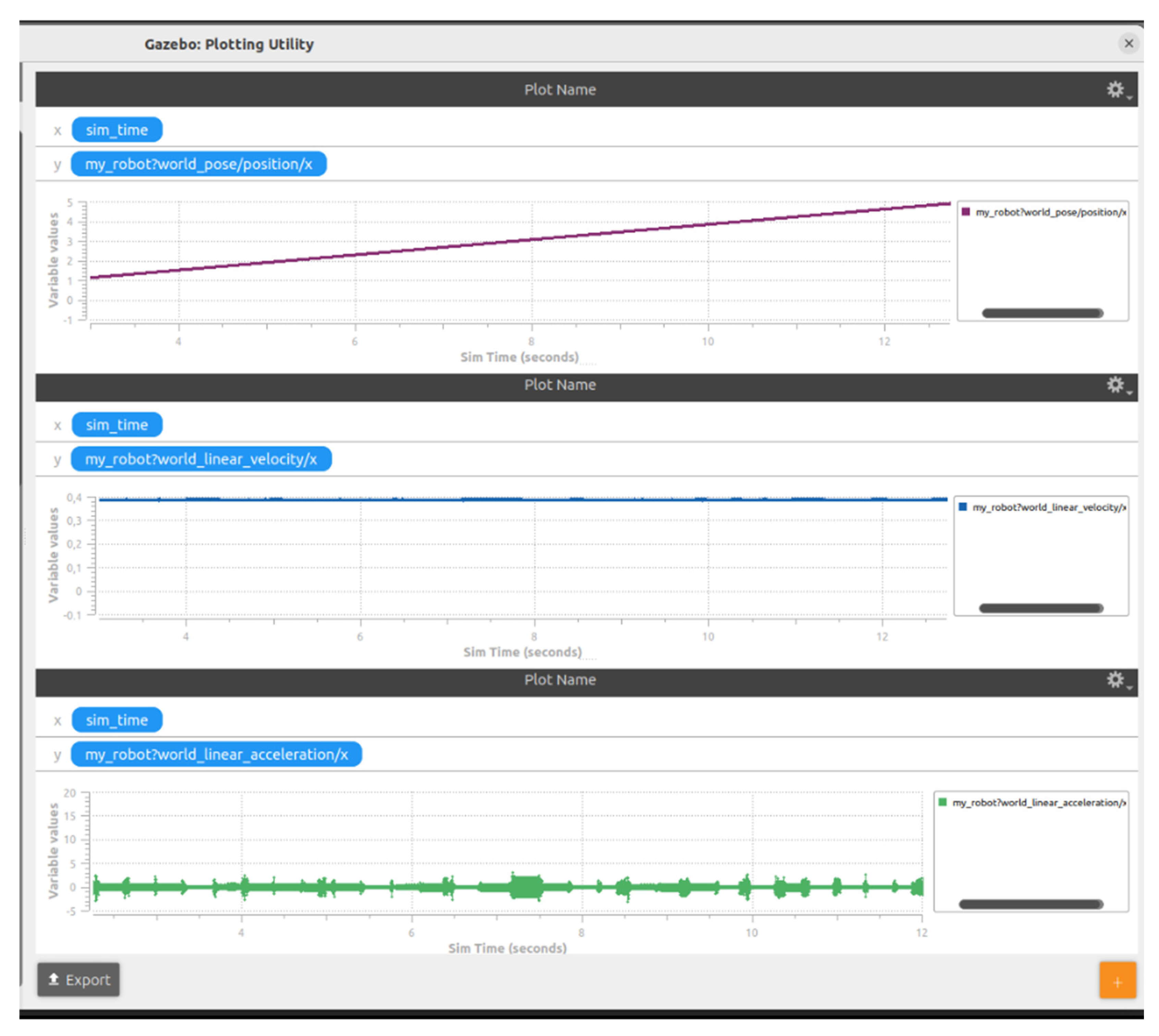
Figure 23.
Gazebo–ROS Communication Configuration for the Use of Two Mobile Robots.
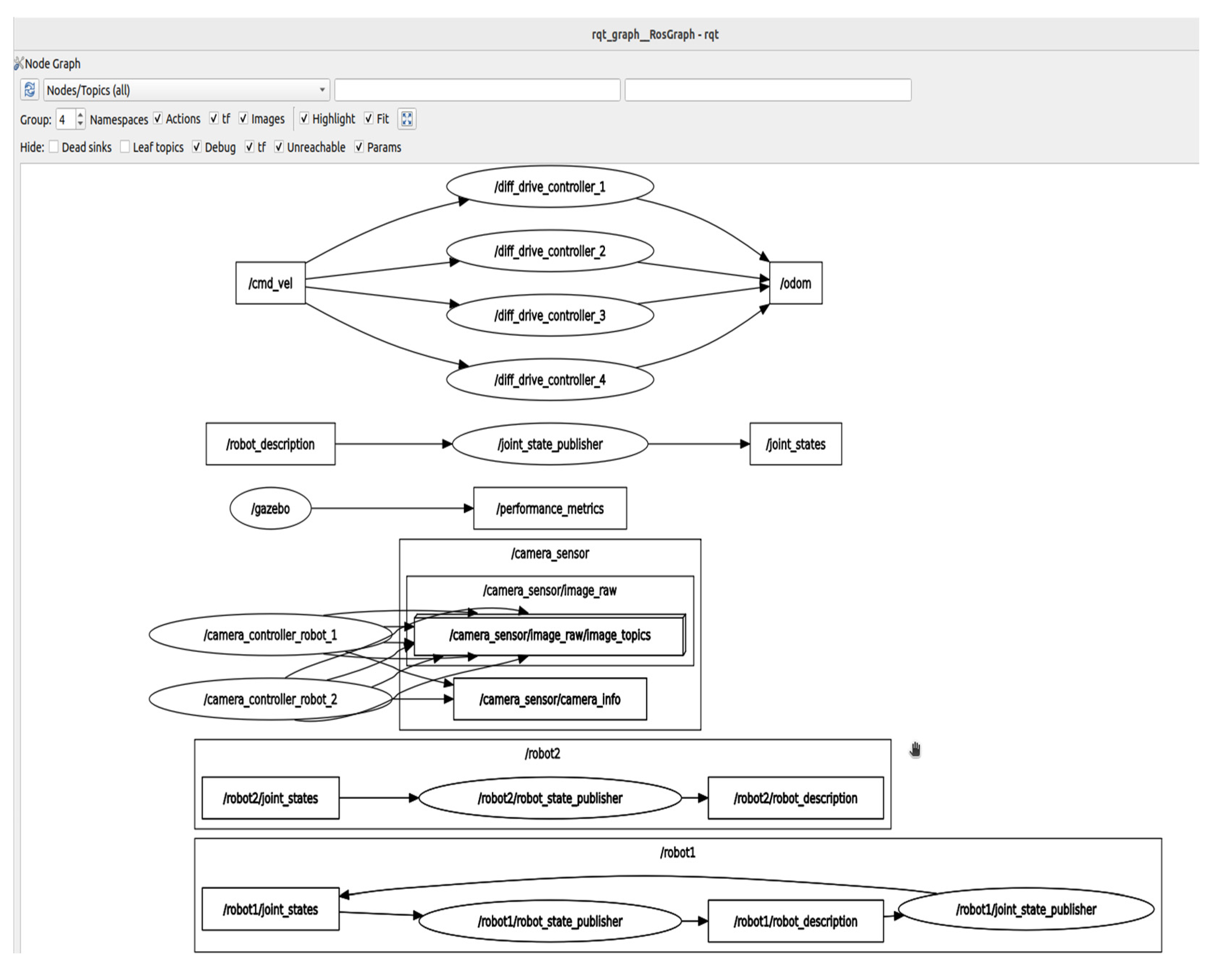
Figure 24.
Connecting Two Mobile Robots within the Gazebo Simulation Environment.
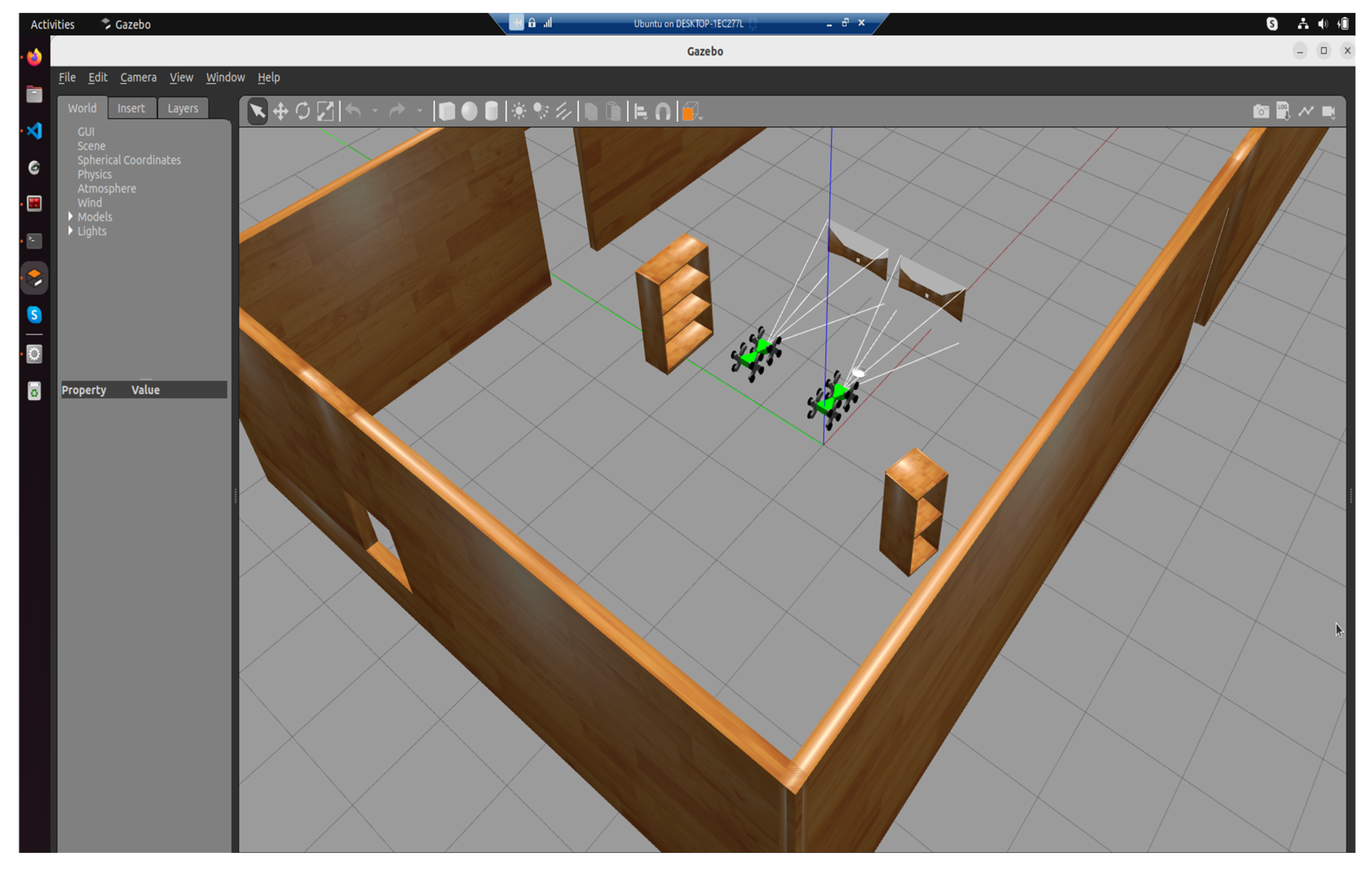

Table 1.
Description of mobile robot links.
| No. | Description |
|---|---|
| 1 | Left-rear locomotion unit (A_link) |
| 2 | Right-rear locomotion unit (B_link) |
| 3 | Left-front locomotion unit (C_link) |
| 4 | Right-front locomotion unit (D_link) |
| 5 | Rear chassis segment (base_link) |
| 6 | Front chassis segment (Y_link) |
| 7 | Central coupling joint (X_link) |
*= in ROS2 and Gazebo, these joints are represented as revolute joints.
Table 2.
Robotic Search and Reasque Mission Flow.
| Phase/Robot | Functionalities and methods |
|---|---|
| Pre-Emergency Signal | WaitForEmergencySignal() + ValidateSignalIntegrity() + IdentifySignalSource() + ClassifyEmergencyType() + PrioritizeZonesBasedOnRisk() + ConfirmAvailabilityOfAllRobots () |
| Robot1_Ground (Exploration Phase) | NavigateToAssignedZone() StartSensorSweep() DetectVictimsUsingThermalAndUltrasound() StreamDataToCommandCenter() ReassessPathIfObstacleDetected() If VictimLocated Then TagLocation() + PlaceRescueLocator() |
| Robot2_Ground (Exploration Phase) | NavigateToAssignedZone() EnableObstacleAvoidance() PerformThermalAndGasScan() SyncDataWithRobot1() CrossReferenceFindings() If VictimLocated Then SendAlert + InitiateAssistanceProtocol() |
| Robot3_Aerial (Exploration Phase) | LaunchFromBase() AscendToOptimalAltitude() PerformWideAreaThermalMapping() DetectAnomalies() GenerateLiveTopographicalMap() TransmitFindings() MonitorRobotNavigation() ReturnToBase() |
| Coordination & Shutdown | CollectAllRobotData() GenerateRescuePlan() DispatchRescueTeamToVictimLocations() LogMissionOutcome() ShutdownAllRobots() |
Disclaimer/Publisher’s Note: The statements, opinions and data contained in all publications are solely those of the individual author(s) and contributor(s) and not of MDPI and/or the editor(s). MDPI and/or the editor(s) disclaim responsibility for any injury to people or property resulting from any ideas, methods, instructions or products referred to in the content. |
© 2025 by the authors. Licensee MDPI, Basel, Switzerland. This article is an open access article distributed under the terms and conditions of the Creative Commons Attribution (CC BY) license (http://creativecommons.org/licenses/by/4.0/).
Copyright: This open access article is published under a Creative Commons CC BY 4.0 license, which permit the free download, distribution, and reuse, provided that the author and preprint are cited in any reuse.


