
Submitted:
07 April 2025
Posted:
08 April 2025
You are already at the latest version
Abstract
This paper introduces a configuration and integration model for mobile robots deployed in emergency and special operations scenarios. The proposed method is designed for implementation within the Operational Technology (OT) domain, enforcing security protocols that ensure both data encryption and network isolation. The primary objective is to establish a dedicated operational environment encompassing a command and control center, where the robotic network server resides, alongside real-time data storage from network clients and remote control of field-deployed mobile robots. Building on this infrastructure, operational strategies are developed to enable efficient robotic response in critical situations. By leveraging remote robotic networks, significant benefits are achieved in terms of personnel safety and mission efficiency minimizing response time and reducing the risk of injury to human operators during hazardous interventions. The technologies employed create a synergistic system that ensures data security, encryption, and user interaction through a web-based interface. Additionally, the system includes mobile robots and a read-only application positioned within the DMZ (Demilitarized Zone), allowing for secure data monitoring without granting control access to the robotic network.
Keywords:
mobile robots
; OT network integration
; security encryption
; DMZ applications
1. Introduction
Data security has become a critical concern in the development of robotic network architectures, primarily due to the increasing risk of information theft through various hacking techniques. As a result, operational environments involving the management and control of intelligent machines demand the integration of secure communication protocols within the OT (Operational Technology) domain. This ensures that data transmission across such systems remains encrypted and protected.
In this context, emergency scenarios involving mobile robotic networks, Swarm [1] or Networked systems [1] require dedicated communication and data protection strategies to prevent interception or data breaches. As highlighted in [2,3], robotic network data is susceptible to a wide range of cyberattacks, including phishing, man-in-the-middle, and internal threats.
Reference [4] outlines the benefits of using mobile robotic networks for enhanced data acquisition from sensor-based systems via WSRNT (Wireless Sensor and Robot Network with Teleoperation). Additionally, the integration of mobile robots into secure networks is reinforced through the adoption of emerging IoT based technologies such as the Internet of Robotic Things (IoRT) [5]. This paradigm enables remote control capabilities via cloud computing platforms while ensuring secure access and data exchange.
Moreover, the review article “Control Methods for Internet-Based Teleoperation Systems” [6] examines how latency and communication infrastructure scalability affect robot teleoperation. Intelligent control mechanisms are thus essential, as discussed in [7], where adaptive and robust control methods are compared. A reliable approach for managing such control involves defining structural schemes that map robotic control events, as introduced in [8], which utilizes programmatic functions to link control blocks.
In line with these approaches, the present study proposes a secure data management framework for mobile robotic networks in emergency scenarios. This is achieved by implementing a dedicated operational domain managed by a central command and control server, which oversees and coordinates all necessary functionalities for optimal system performance.
Figure 1 illustrates and explains the two primary domains of the Internet: IT (Information Technology) and OT (Operational Technology), along with their general functionalities. The IT domain refers to the unsecured and openly accessible segment of the Internet, typically used for general-purpose information and public services. In contrast, the OT domain encompasses secure environments, often associated with industrial systems and intelligent machine infrastructures, where sensitive operational data is managed.
The OT domain contains so-called “gateways” to the IT domain, which allow users to remotely connect to specific networks via virtualization technologies. Any user attempting to access the OT environment must undergo a secure registration process, including multi-factor authentication (MFA), to ensure safe and controlled access.
The proposed robotic network architecture is based on a server–client communication protocol and incorporates multiple data security and encryption mechanisms, including TLS (Transport Layer Security) and hash-signing technologies.
This paper is structured into six sections, each detailing a specific phase in the development of robotic networks aimed at supporting emergency response operations. Section 2 addresses the design and implementation of the robotic network architecture, highlighting the communication protocols employed, the development strategy for both code and security protocols, the client-to-server connection model, and the methodology for storing and archiving data exchanged between field units and the control system.
Section 3 introduces a read-only application developed within the DMZ (Demilitarized Zone), featuring enforced firewall rules that allow unidirectional data flow specifically, from OT to DMZ. This application enables limited data visualization while fully restricting network control capabilities.
Section 4 presents the results obtained during the development and testing of the robotic network, including system log outputs. Section 5 outlines potential future paper, focusing on the implementation of network redundancy strategies. Finally, Section 6 provides the concluding remarks of this study.
2. Definition and Development of the Robotic Network Within the OT Domain
As previously discussed, this study proposes the integration of a server–client-based robotic network within the Operational Technology (OT) domain using virtualization technologies. The architecture defines the connection between the server and its clients, including mobile robots and web browsers—through Wi-Fi communication, as illustrated in Figure 2 [8].
The first step in the development of the robotic network involves the definition and securement of the Command-and-Control center.
2.1. Architecture and Deployment of the Command and Control Unit
The Command-and-Control Unit is implemented as a virtual machine (VM), deployed and secured using the AWS EC2 service. This virtual instance hosts a robotic network server and enables remote user access through a web-based platform. The VM runs on a Windows Server operating system and can be accessed via the Remote Desktop Protocol (RDP), following a defined authentication and connection procedure:
- The user must know the public IP address of the VM instance;
- The AWS VM instance administrator must allow inbound traffic from the user’s IP address, enabling the authentication process;
- The user must possess a valid username and password for access;
- The password is generated using a self-signed certificate and is securely shared with the user by the VM administrator;
- The user launches the Remote Desktop Protocol (RDP) application and enters the VM’s public IP address to initiate the remote connection.
Integrating the server into a virtual machine that can be accessed remotely enhances the flexibility of the command-and-control team by enabling simultaneous access from multiple geographic locations.
Figure 3 illustrates the network positioning of the command center, the server, and the login pathways for both users and client devices. The figure also outlines the functional relationship between the network server, the web platform, and the relational database management system (RDBMS).
All network components communicate with the central server, transmitting data to it, and are required to register and authenticate before interaction is permitted.
The following subsection defines and explains the core functionalities of the robotic network server by detailing its main operational components and services.
2.2. Architecture and Deployment of the Robotic Network Server
The robotic network server serves as the central entity responsible for processing all network data and facilitating communication with the other components of the infrastructure—specifically, its connected clients. The main responsibilities of the robotic network server are as follows:
- Maintaining the network in an operational and stable state (Up and Normal – UN);
- Sustaining continuous connection with browser-based clients;
- Sustaining continuous connection with mobile robot clients;
- Ensuring the Web Platform remains fully operational (UN – Up and Normal);
- Maintaining an active and stable connection with the postgresql RDBMS (Up and Normal);
- Securely processing incoming data from all connected clients;
- Transmitting control commands to client devices.
The functionalities of this server were developed using web backend technologies, employing asynchronous data processing to handle multiple HTTP/S requests concurrently. Server security is ensured through the use of WSS-based connections, which rely on certificates issued by a trusted Certificate Authority (CA), as well as WebSocket (WS) communication secured with hash-signature-based authentication.
2.3. Definition of Network’s Clients
The clients of the robotic network are virtual entities that maintain a continuous and secure connection with the Command-and-Control Center. These clients connect to the server and issue HTTP/S requests as part of their interaction.
The clients are divided into two main categories: the mobile robots that operate within the robotic network, and the web browsers used to display data to end users via the web platform.
This approach leverages modern Internet of Things (IoT) functionalities to automate emergency missions and significantly reduce the need for human presence in the field.
The robotic network clients that connect to the server employ distinct protocols for authentication and registration within the network:
- Mobile robots (connection via hash-sign protocol)
- Web browsers running the webplatform (gui interface), which use connection via tls/ssl protocol with certificates signed by a certificate authority (ca).
For the network testing phase, the integration of three mobile robots into the system is proposed, aiming to establish interconnectivity. These robots are illustrated as 3D models in Figure 4 [8] a), b) and c).
These mobile robots are identified based on the MAC address of the microcontroller used, through the generation of an encrypted digital signature. The network can be easily extended by adding additional mobile robots, provided that the MAC addresses of their microcontrollers are known. It is mandatory for each MAC address to be present in the server’s database in order to instantiate the registration process within the network. This specific address was chosen for signature generation because it is static and uniquely represents each mobile robot’s control unit. The digital signature used for network registration may vary depending on the hash method employed for encryption. Table 1 [8] lists the MAC (Media Access Control) addresses of mobile robot clients that will authenticate and register within the network.
The computed digital signature is transmitted to the server, and if successfully recognized, the mobile robot will authenticate and register within the network as a valid client.
The communication strategy among the network components is based on the use of secure protocols and is detailed in Subsection 2.4.
2.4. Communication Strategy
This network utilizes two secure communication protocols to connect all its components. For communication between browser-based clients and the server, the WebSocket Secure (WSS) protocol is used, while mobile robot clients communicate with the server via the WebSocket (WS) protocol [8]. Figure 5 illustrates the communication flow using these technologies [8].
Bidirectional communication refers to the ability of all network members to initiate HTTP/S requests and exchange data whenever necessary. Data encryption is achieved through the use of a secure communication tunnel based on the TLS (Transport Layer Security) methodology. This approach significantly mitigates the risk of Man-in-the-Middle attacks, which involve data interception during transmission to a third-party entity.
The standard port used for WSS connections is :443 on Windows-based machines and :8443 on Linux-based machines. Subsection 2.5 provides a detailed explanation of the network’s security protocol implementation.
2.5. Strategia și Protocoalele de Securitate
Data security and encryption are critical aspects when transferring information to and from the network. Therefore, multiple security protocols are employed to ensure the protection and encryption of the robotic network.
2.5.1. Communication Protocol Between the Server and Browser-Based Clients
To establish a secure connection between the server and browser-based clients, the WSS communication protocol is used. WSS is a real-time, bidirectional communication protocol between a server and client, which transmits data through a secure tunnel based on the TLS (Transport Layer Security) protocol.
The designated port for WSS connections is :443, as the server is hosted on a Windows-based machine. Data encryption and client authentication are secured using digital certificates signed by a trusted Certificate Authority (CA).
To limit and protect network traffic, browser clients are required to verify their identity before logging into the server using valid credentials. This identity verification is performed using SSL (Secure Socket Layer) security certificates, which are designed to secure communication via the TLS protocol.
2.5.2. Communication Protocol Between the Server and Mobile Robot Clients
To establish communication between the server and mobile robot clients, the WS (WebSocket) protocol is used. This is a real-time, bidirectional communication protocol between a server and a client. Unlike WSS, WS operates through an unsecured channel.
In order for the mobile robots to successfully connect and verify their identity, each robot transmits a digital signature to the server for authentication. This digital signature is encrypted and includes the device’s MAC address. The encryption process involves encoding the signature using a hash function implemented via the Base64.h library. The signature is generated from a String package composed of the MAC address and a secret key, which is then hashed to produce the final signature.
The server’s internal database contains the same hash function and the MAC addresses of all eligible robots authorized to connect. If the signature generated by the client matches the one stored and computed by the server, the client is granted access and is marked as “Connected.”
All data exchanged between the server and this category of clients is encrypted using the same hash-based method and decrypted upon arrival. As a result, intercepted data may be captured, but remains unreadable without knowledge of the specific hash function used for decryption.
2.5.3. Communication Protocol Between the Server and the RDBMS
The robotic network uses a Relational Database Management System (RDBMS) for data storage and archiving. To ensure secure communication between the server and the RDBMS, the WSS protocol with TLS encryption is employed. For server authentication with the PostgreSQL database, digital certificates signed by a Certificate Authority (CA) are used, similar to the browser client authentication mechanism.
2.6. WebPlatform
The WebPlatform of the robotic network consists of a set of web pages developed using HTML, CSS, and JavaScript technologies. Its primary purpose is to display data and enable the control of mobile robots.
The WebPlatform is composed of five main web pages:
- Authtentication page;
- Dashboard (main page);
- 3 manual control of robots movement pages (for each mobile robot).
The WebPlatform connects to the server via WSS on port :443. A WSS connection is therefore established to send and receive data from the server.
2.6.1. WebPlatform’s Authentication Page
The login page of the WebPlatform is always the first interface displayed when accessing any of the web pages (e.g., through a direct route link). The WebPlatform’s security is designed so that any user attempting to access a route without prior authentication is automatically redirected to the login page.
2.6.2. WebPlatform’s Dashboard Page
The main page of the WebPlatform serves as the central interface for accessing all network functionalities. It includes a real-time monitoring section for mobile robots, receiving data from the server such as sensor values and location, as shown in Figure 8 [8]. Additionally, the robot’s position can be tracked on integrated maps using the Leaflet API. At the bottom of each section, users can access the manual control page, which provides movement control functions for the mobile robot.
2.6.3. WebPlatform’s Manual Movement Control Page for Robots
The manual control page for mobile robots, shown in Figure 8 [8], is accessible from the main WebPlatform interface. Its purpose is to allow the transmission of manual movement commands to mobile robots operating in the field. This functionality was developed to be used in scenarios where a mobile robot becomes stuck or encounters a situation that cannot be resolved autonomously.
For the testing phase, the control of two DC motors via a dual H-bridge was implemented for the mobile robot with the ID Robot_1. Four control methods were developed for managing the motors, as illustrated in Figure 10 [6], where robot IDs are used for their identification.
- move_forward();
- move_backward();
- turn_left();
- turn_right();
- stop();
These commands are also transmitted from the WebPlatform through the secure TLS port :443 using a WSS socket toward the field units. The next development stage involves enhancing the manual control pages of the mobile robots by integrating real-time video feed sections for field monitoring.
2.7. Data Storage and Archival
An essential functionality of such a control system is the storage and archiving of data within a Database Management System (DBMS). For the robotic network, a Relational Database Management System (RDBMS) was selected, as it allows data to be stored in structured tables. The chosen RDBMS is PostgreSQL, a widely used and reliable database management system. Figure 11 [8] illustrates the database configuration designed to store values received from mobile robots operating in the field.
Connecting to and storing data in a database contributes to building a historical record of the robotic network. Database systems offer high data availability, allowing secure access to stored information through appropriate security protocols. This enables the creation of operational scenarios, data comparisons, and strategic planning based on historical data analysis. Additionally, storing data outside the memory of the mobile robot microcontrollers enhances network security by preventing potential information leakage.
All these functionalities contribute to a complete and secure data communication system, both within and outside the robotic network. Based on this infrastructure, control scenarios for mobile robots can be developed using algorithmic approaches.
Section 3 extends the functionality of the robotic network into the DMZ (Demilitarized Zone) by proposing the development of a read-only application. This application receives read-only data from the OT domain, where the command center and the network server are located, and is intended for users who interpret data and perform analytical tasks based on it. These users are not granted control over the network; they are only permitted to view specific functional components.
3. Development of Read-Only Applications Within the DMZ Domain
Read-only applications are implemented within the DMZ (Demilitarized Zone) of the Internet to allow the retrieval of specific data from the robotic network.Securing this domain involves enforcing firewall rules that permit data flow in only one direction—from the OT (Operational Technology) domain to the DMZ. For the development of this application, firewall rules will be defined to reject unauthorized HTTP/S requests and to secure the communication tunnel using the TLS protocol, with certificates signed by a trusted Certificate Authority (CA). Figure 12 illustrates the data flow mechanism by defining the unidirectional communication path between the OT and DMZdomains.
This application is hosted on an application server and consists of a single page that displays only the data permitted for visualization by DMZ users, as shown in Figure 13 [8]. The read-only application page is similar to the main page of the WebPlatform in the OT domain, except it does not include any network control functionalities.
It is important to note that this application is visible only when the network server within the OT domain is operational.
4. Results of the Robotic Network Development
The development of the robotic network across the OT and DMZ domains, with connections extending into the IT domain, has provided significant insights into the core principles of integration, security, and encryption for networks involving mobile robots in emergency response scenarios. As a result, the main achievements of this paper are as follows:
- 2.
- Development of the network server functionalities through the implementation of asynchronous code and the use of functions that orchestrate data flow;
- 3.
- Definition of the robotic network clients and their classification into two categories: mobile robots and browsers running the WebPlatform application;
- 4.
- 5.
- Network’s data encryption;
- 6.
Additionally, Figure 17 [8] presents the log of the mobile robot with the ID Robot_1, which successfully receives and sends requests to and from the network server.
- 7.
- Development of a web-based read-only application within the DMZ domain, designed for visualizing specific network data and enabling unidirectional communication from OT to DMZ;
- 8.
- Preparation of a command and control infrastructure as a foundation for developing scenarios aimed at optimizing emergency response situations;
These functionalities require further extension in the area of redundancy for both the command-and-control center and the RDBMS, in order to ensure high data availability in case of an online server connection failure.
5. Future Research, Development and Deployment
These intelligent systems are developed progressively and follow Continuous Integration (CI) and Continuous Deployment (CD) processes, ensuring long-term usability in operational environments.
In the same context, the robotic network will undergo continuous development, optimization, and integration through the addition of new functionalities and the improvement of existing ones. Therefore, the authors propose several directions for future research and development.
The first and most important proposed direction for research and development is the implementation of a failover system within the network. This process involves introducing redundancy for the command center, the server, and the RDBMS of the robotic network. Figure 18 [8] illustrates a schematic of the failover strategy with two levels of redundancy, by defining two sites: the Primary Site (CC) and the Backup Site (BCC).
This creates two levels of redundancy for the command center and the robotic network server. The failover process is instantiated when the online server enters a failure state, and a backup server takes over control of the network in real-time. Additionally, when the primary site enters a failure state, the backup site automatically assumes control.
The second research direction focuses on the redundancy (also with two levels) of the database system. The authors propose a DBMS redundancy solution by utilizing a NoSQL Cassandra system. This technology provides increased data availability in a horizontal direction, in the event that the online node enters a failure state. Figure 19 [8] illustrates the connection and configuration of the data centers.
The database redundancy principle is based on the formation of a ring system with four data centers, which are continuously updated in real-time. In the event of a failure in the online DBMS, the backup DBMS will take control, provide, and archive the robotic network data.
Additionally, this network has been developed to integrate mobile robots within it, making the third area of further research and development the simulation of these robots in a virtual environment. This includes the creation of scenarios, hypotheses, and conclusions regarding the behavior of all network elements in special emergency situations. One possible approach is the use of the ROS2 robotics operating system [10] and the Gazebo physics simulation environment. ROS2 is capable of running web microservices [11], making the integration of the ROS2 environment with the robotic network seamless.
After dynamic simulation with ROS2 and Gazebo [12], the next step is to build physical mobile robots to test their locomotion capabilities [13]. These technologies are compatible with Arduino microcontrollers, enabling the development of control applications for mobile robots within the network [15].
All of these proposed research and development directions are seen by the authors as key points in generating an intelligent and optimized system for the semi-autonomous management of special emergency situations.
6. Conclusions
In conclusion, robotic networks provide significant advantages in emergency response solutions by developing a collaborative team model. Swarm networks offer modularity through the use of identical mobile robots [16], while Networked networks enable exploration of diverse environments through the use of both terrestrial and aerial mobile robots.
This paper has developed an infrastructure model for robotic networks by securing data within the OT domain, with the possibility of creating read-only applications in the DMZ domain.
The concept behind the development of such a network is based on research into emergency response solutions, following the trends in the operation, control, and integration of mobile robots within networks, as outlined in the literature [17,18]. The aim of this paper is to expand the use of robotic networks by implementing security elements, data storage, and archiving, placing the command and control center within the OT domain of the Internet. Additionally, a web platform is provided, enabling users to interact graphically with the network functions, while a web-based read-only application is proposed for use within the DMZ domain of the Internet.
Finally, future research and development directions are proposed, focusing on the implementation of redundancy within the robotic network for both the command center and its DBMS.
This paper contributes valuable insights to the enhancement of network architectures integrating mobile robots, particularly in critical contexts. Methods are proposed for enabling effective collaboration between these robots to respond quickly to emergency situations. Emphasis is placed on improving communication, control, and reaction capabilities in unpredictable scenarios. The presented solutions aim to reduce intervention time and increase system reliability, thus providing a modern and practical approach to autonomous management of emergency situations.
Abbreviations
The following abbreviations are used in this manuscript:
| API | Application Programming Interface |
| AWS | Amazon Web Services |
| BCC | Backup Site |
| CA | Certificate Authority |
| CC | Primary Site |
| CD | Continuous Deployment |
| CI | Continuous Integration |
| CSS | Cascade Style Sheet |
| DMZ | Demilitarized Zone |
| EC2 | Eclastic Compute 2 |
| HTML | Hyper Text M |
| HTTP | Hyper Transfer Protocol |
| HTTPS | Hyper Transfer Protocol |
| ID | Identifier |
| IT | Information Technology |
| IoT | Internet of Things |
| JS | JavaScript |
| MAC | Media Access Control |
| MFA | Multi Factory Authentication |
| OT | Operational Technology |
| RDBMS | Relational Database Management System |
| RDP | Remote Desktop Connection |
| SCADA | Supervisory Control and Data Aquisition |
| SQL | Sequel Query Language |
| SSH | Secure Shell |
| SSL | Secure Sockets Layer |
| TLS | Transport Layer Security |
| UN | Up and Normal |
| VM | Virtual Machine |
| VPN | Virtual Private Network |
| WS | WebSocket |
| WSRNT | Wireless Sensor and Robot Network with Teleoperation |
| WSS | WebSocket Secure |
| bS1 | Backup Sever 1 |
| bS2 | Backup Sever 2 |
| pS1 | Primary Sever 2 |
| pS1 | Primary Sever 1 |
References
- Mărieș M.; Tătar M.O.; Contributions to the Development of Network Integration of Mobile Robots for Emergency Situations. Mechanism Design for Robotics (MEDER 2024), part of IFToMM Symposium on Mechanism Design for Robotics, Timișoara, România, 27-29 June 2024, pp. 21-30. 29 June.
- Botta, A.; Rotbei, S.; Zinno, S.; Ventre, G. Cyber Security of Robots: A Comprehensive Survey. Intelligent Systems with Applications, , vol. 18. 2023.
- Kadena, E.; Dai N.; Huu. P.; Ruiz, L. Mobile Robots: An Overview of Data and Security. In Proceedings of the 7th International Conference on Information Systems Security and Privacy (ICISSP 2021), Vienna, Austria, 11–13 February 2021; pp. 291–299.
- Wichmann, A.; Okokpujie, B.D.; Kokou, T. The Integration of Mobile (Bio) Robotics and Wireless Sensor Networks: A Survey. In Computer Communications, Volume 51, 2014; pp. 21–35.
- Kabir, H.; Tham, M.L.; Chang, Y.C. Internet of Mobile Things for Mobile Robots: Concepts, Technologies, Challenges, Applications, and Future Directions. In Digital Communications and Networks, Volume 9, Issue 6, December 2023; pp. 1266–1290.
- Kebria, P.; Abdi, H.; Dahvand, M.M.; Khosravi, A.; Nahavandi, S. Control Methods for Internet-Based Teleoperation Systems: A Review. In IEEE Transactions on Human-Machine Systems, Volume 49, Issue 1, 2018; pp. 32–46.
- Orebäck, A.; Christensen, H.I. Evaluation of Architectures for Mobile Robotics. Auton. Robots 2003, vol .14, pp.33–49.
- Mărieș, M.; Studies and Research on the Operation and Integration of Mobile Robots into Emergency Networks. Scientific Research Report III, Doctoral School of UTCN, Faculty of Road Vehicles, Mechatronics and Mechanics, Department of Mechatronics and Machine Dynamics, Cluj-Napoca, Romania, 2025. Supervizor Professor Tătar, M.O.
- ROS2 Documentation. Available online: https://docs.ros.org/en/humble/index.html (accessed on 08.12.2024).
- Node.js APIs. Available online: https://nodejs.org/docs/latest/api/ (accessed on 08.12.2024).
- Gazebo Sim. Available online: https://gazebosim.org/home (accessed on 08.12.2024).
- Mărieș, M.; Locomotion Studies and Research on Mobile Robots for Emergency Situations. Scientific Research Report II, Doctoral School of UTCN, Faculty of Road Vehicles, Mechatronics and Mechanics, Department of Mechatronics and Machine Dynamics, Cluj-Napoca, Romania, 2024. Supervizor Professor Tătar, M.O.
- Arduino Official Site. Available online: https://app.arduino.cc/sketches?custom_banner=cloud_banner (accessed on 08.12.2024).
- Renard, E. ROS 2 from Scratch: Get Started with ROS 2 and Create Robotics Applications with Python and C++; Edouard Renard Publishing: France, 2021. [Google Scholar]
- Brambilla, M.; Ferrante, E.; Birattari, M.; Dorigo, M. Swarm Robotics: A Review from the Swarm Engineering Perspective. Swarm Intell. 2013, 7, pp.1–41. [Google Scholar] [CrossRef]
- Moniruzzaman, M.; Rassau, A.; Chai, D.; Islam, S.M.S. Teleoperation Methods and Enhancement Techniques for Mobile Robots: A Comprehensive Survey. Robot. Auton. Syst. 2022, vol. 150.
- Zaborniak, D.; Balik, P.; Woźniak, K.; Sulikowski, B.; Witczak, M. Iterative Learning Control Design for a Class of Mobile Robots. Electronics 2024, 13, 1043. [Google Scholar] [CrossRef]
- Grosjean, L.; Sachs, J.; Ansari, J.; Reider, N.; Hernandez Herranz, A.; Holmberg, C. A Framework for Communication–Compute–Control Co-Design in Cyber–Physical Systems. Electronics 2024, 13, 1131. [Google Scholar] [CrossRef]
Figure 1.
Funcționalitățile generale ale domeniilor IT și OT.
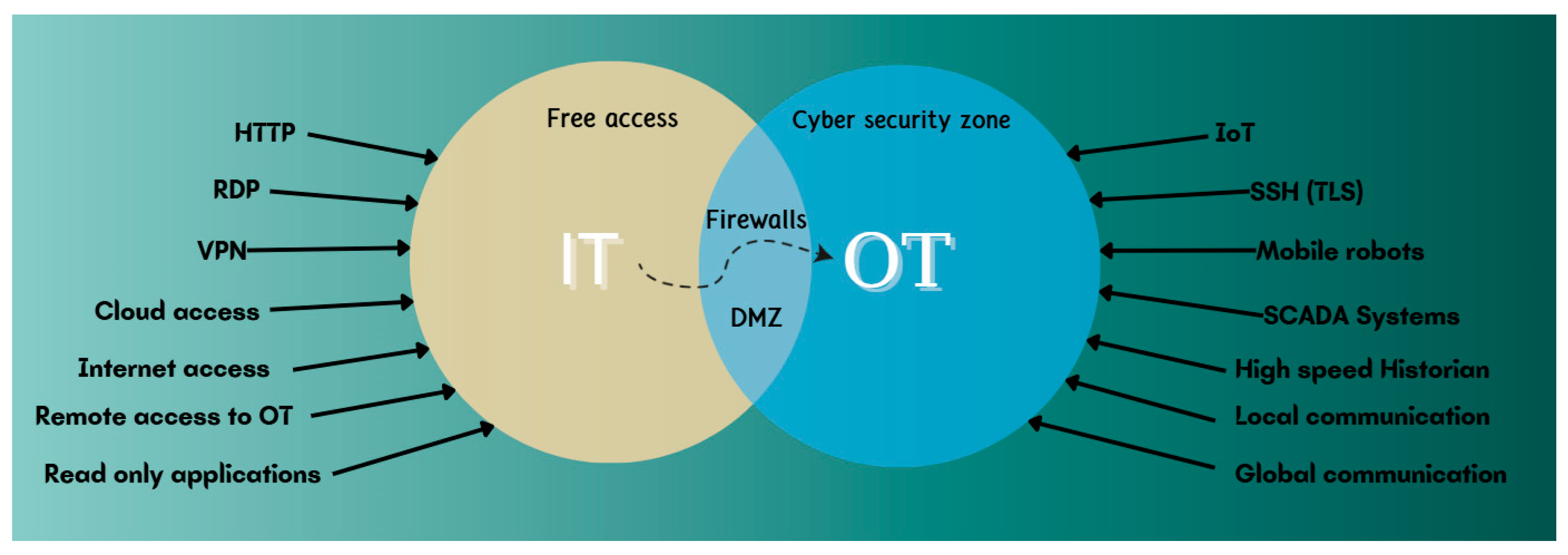
Figure 2.
High-Level Structural Overview and Robotic Network Architecture.
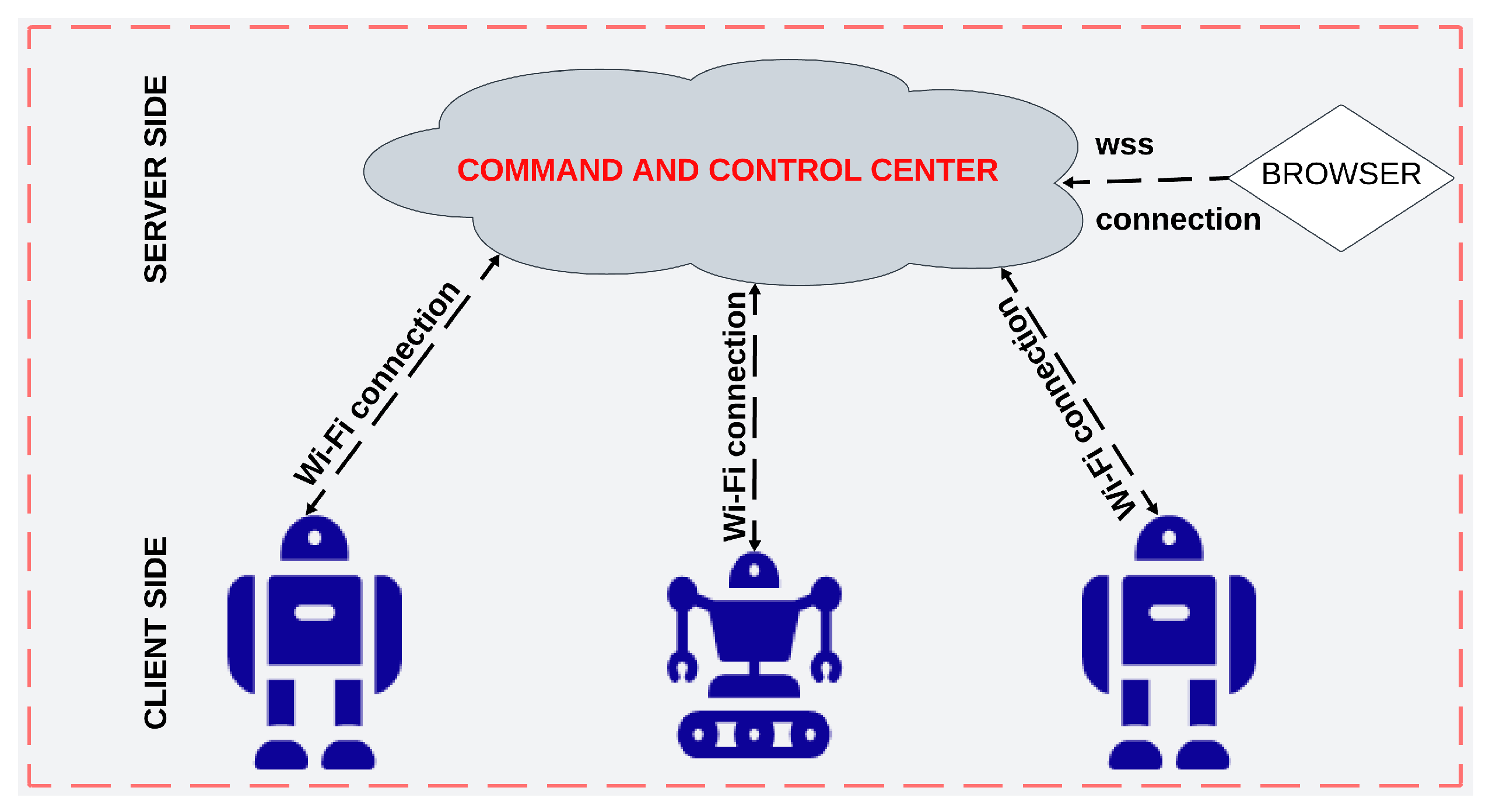
Figure 3.
Authentication Workflow for the VM and Robotic Network Server.
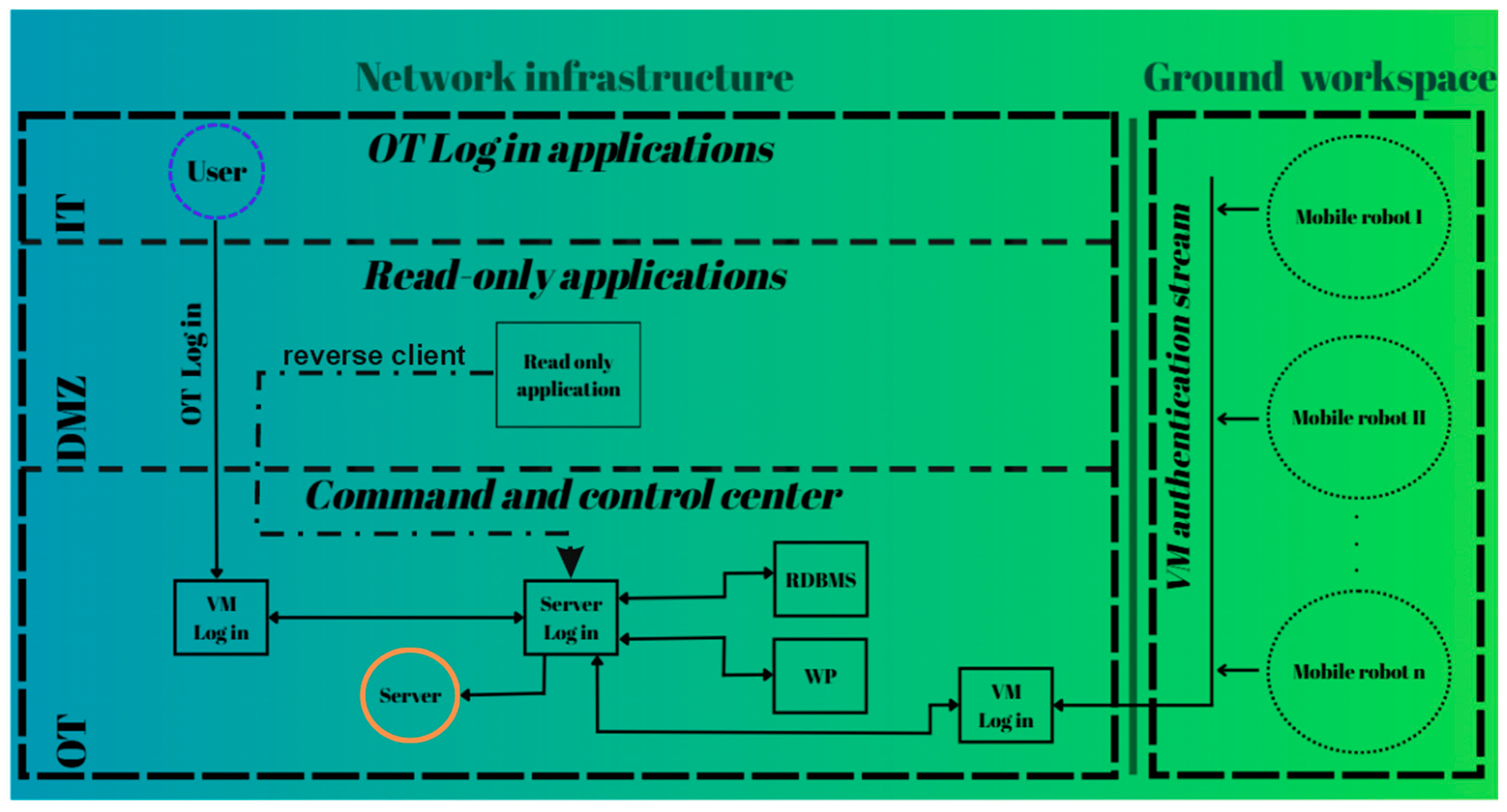
Figure 4.
Login Methods of Network Components to the Command Center and Server.
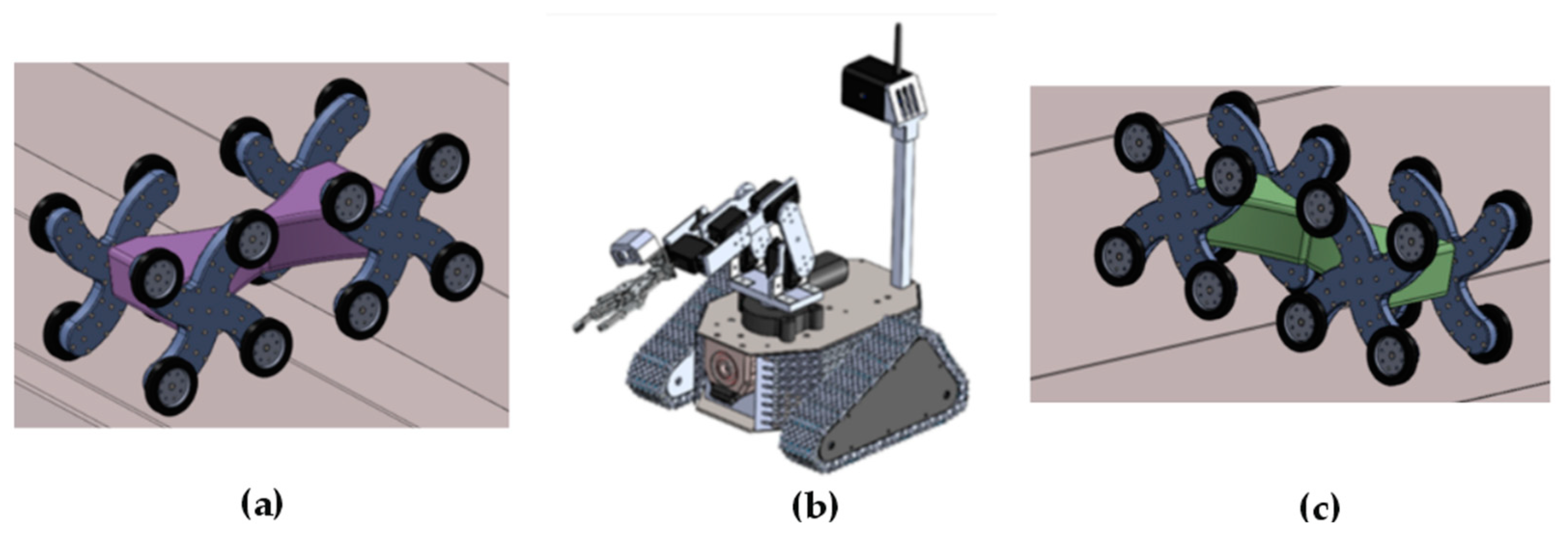
Figure 5.
Communication Strategy Between the Robotic Network and Its Clients.
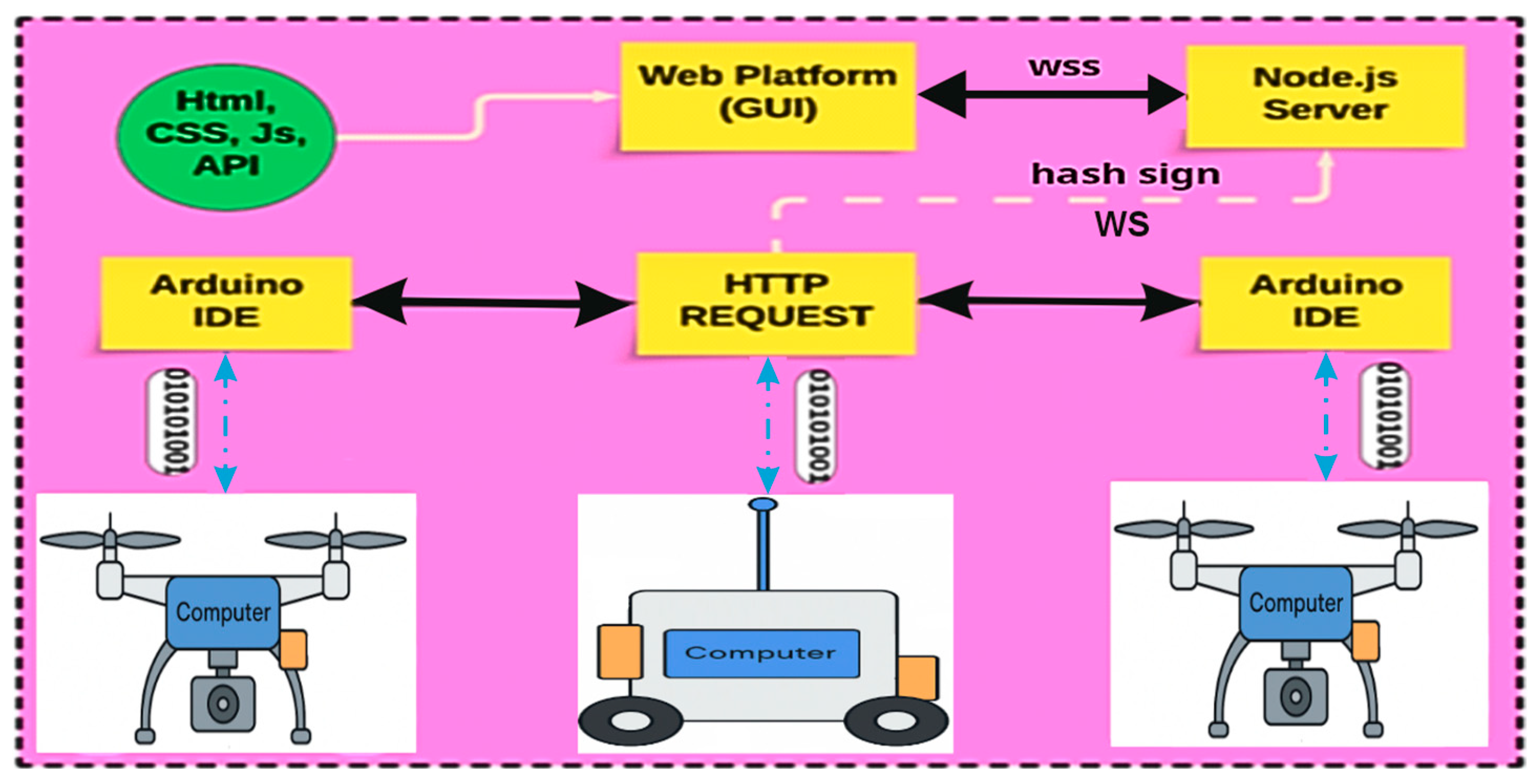
Figure 6.
Querying the Configuration Table pg_stat_ssl.
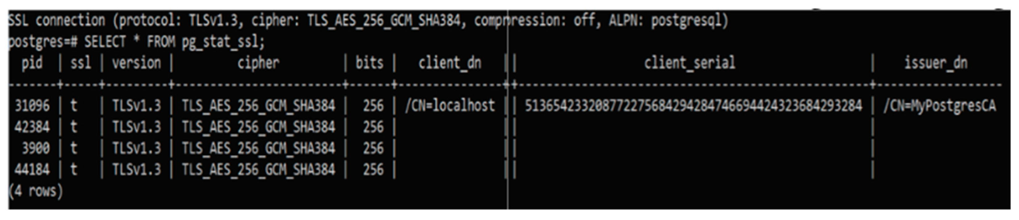
Figure 7.
WebPlatform’s authentication page.
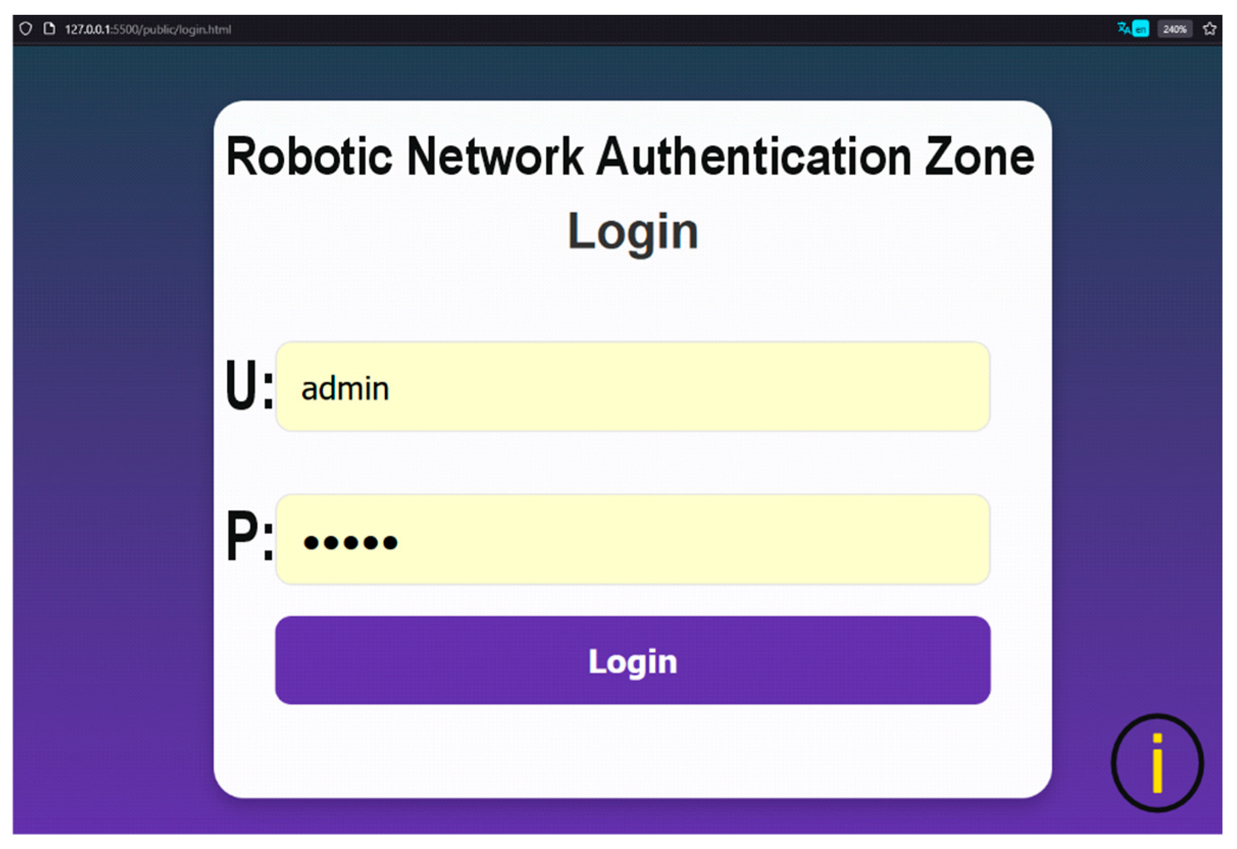
Figure 8.
WebPlatform’s authentication page.
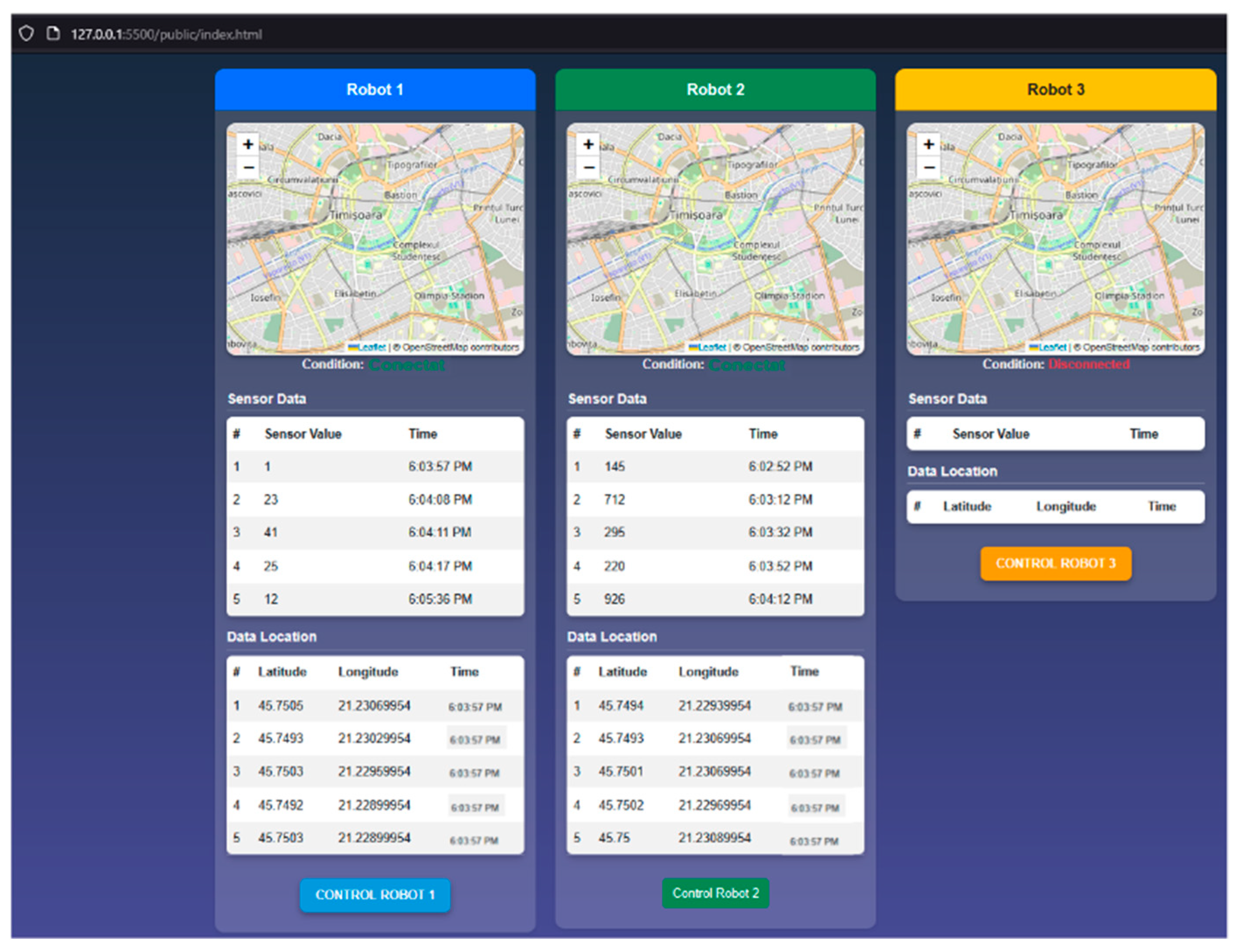
Figure 9.
Control Page for the Mobile Robot with ID Robot_1.
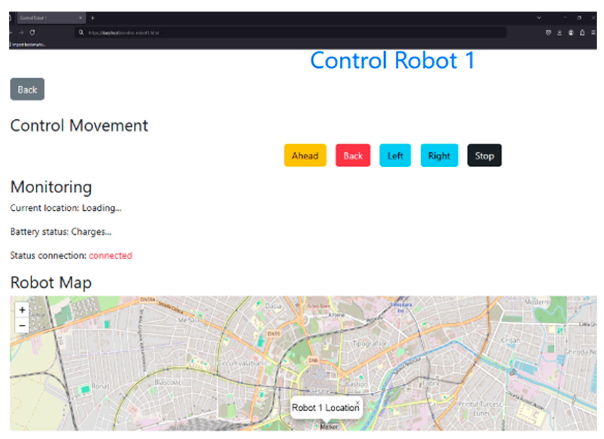
Figure 10.
Movement Function Methods for Mobile Robots.
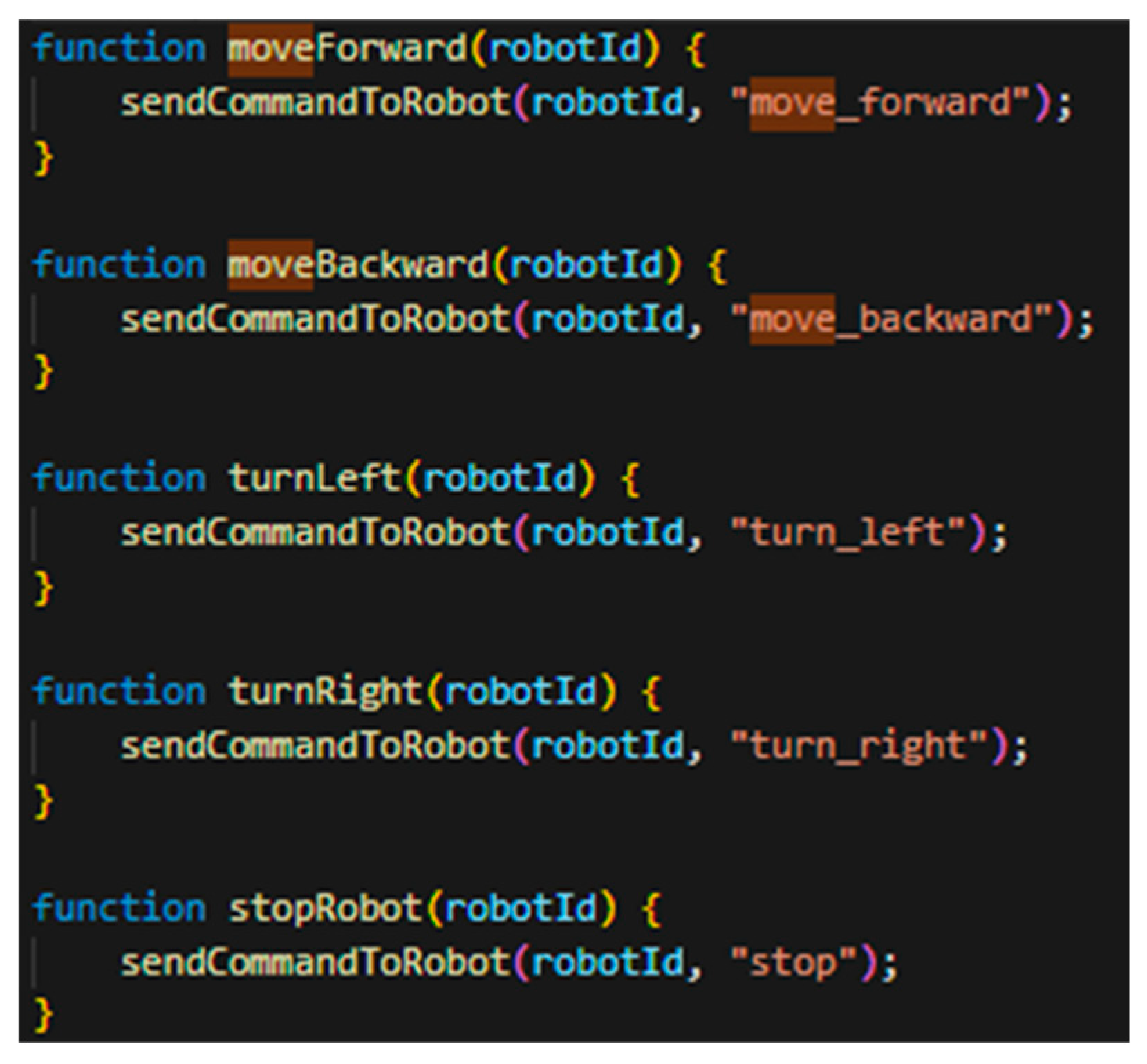
Figure 11.
Setup and deployment of SQL database.
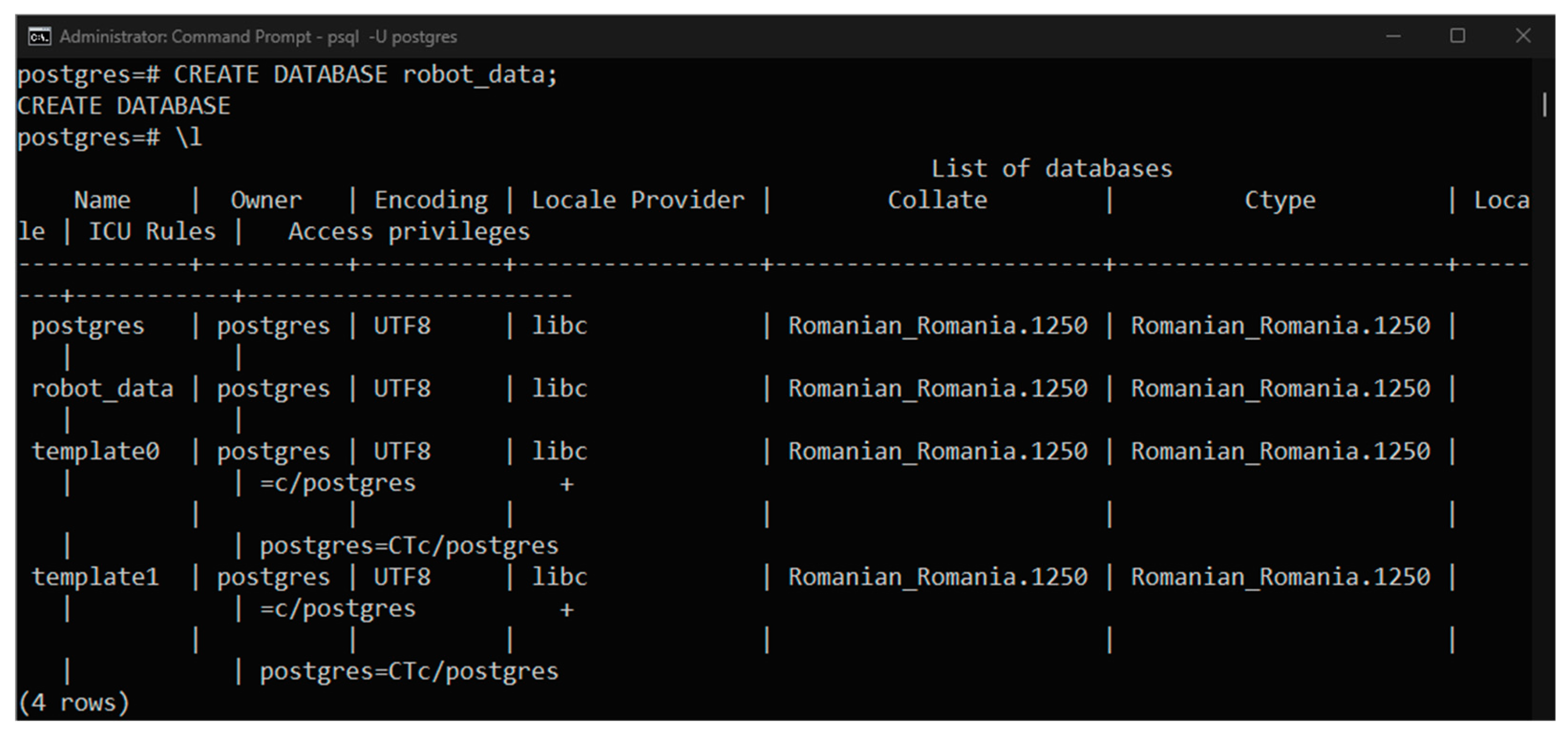
Figure 12.
Communication and Security Between the OT and DMZ Domains.
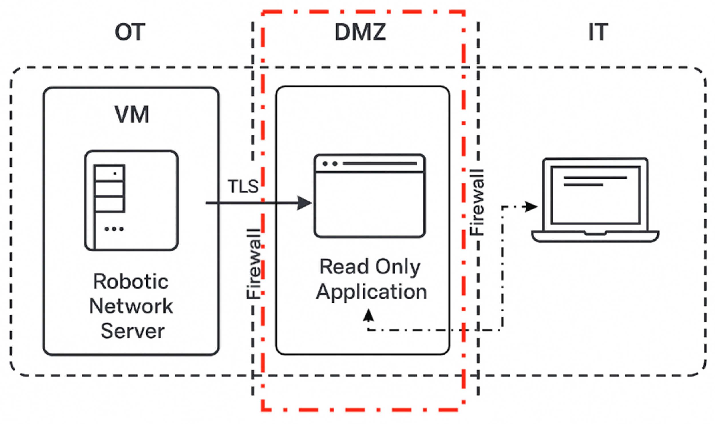
Figure 13.
Read-only appication’s web page.
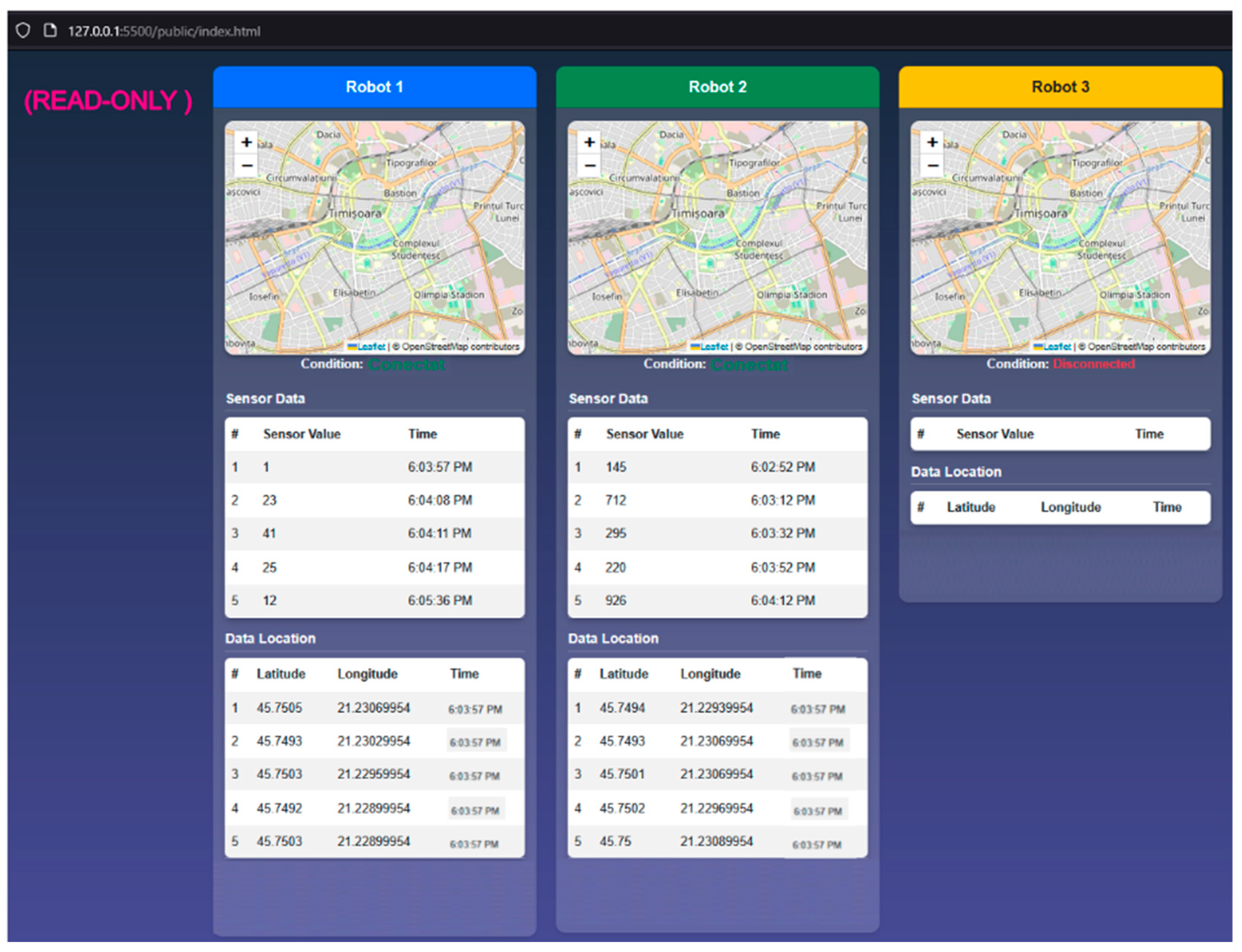
Figure 14.
Specificațiile VM-ului creat în AWS EC 2.
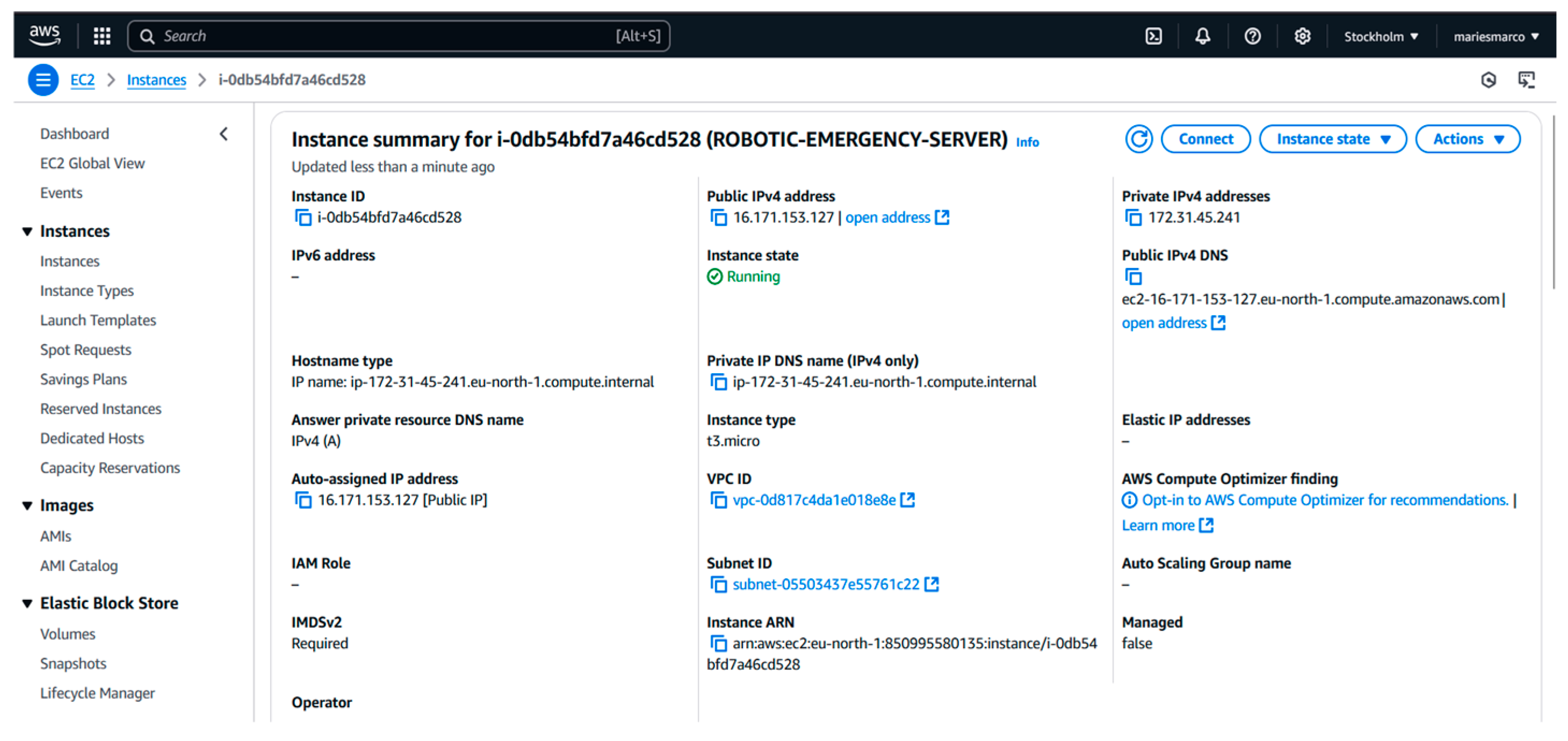
Figure 15.
Server Log Related to Client Network Authentication.
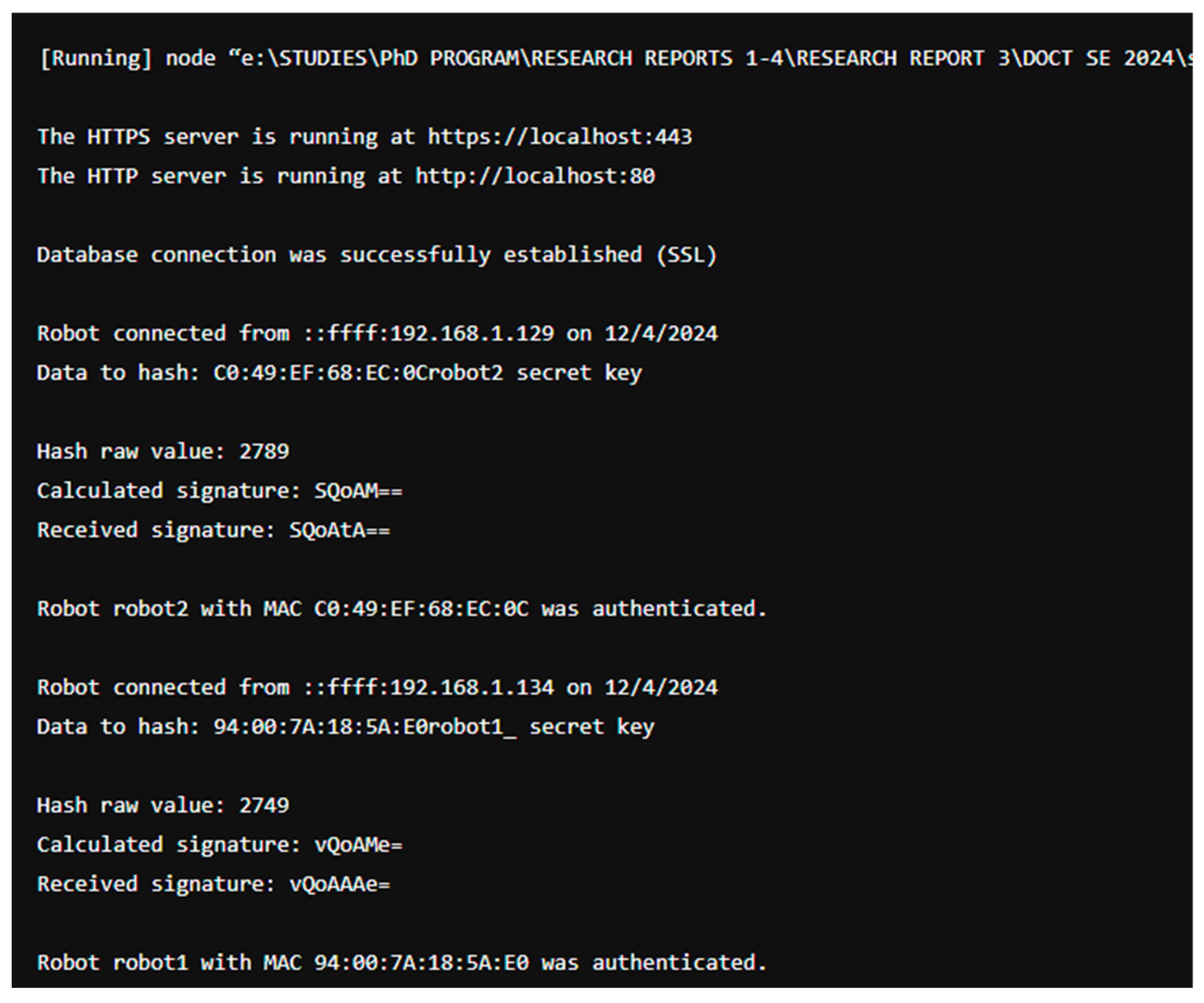
Figure 16.
WebPlatform’s log.
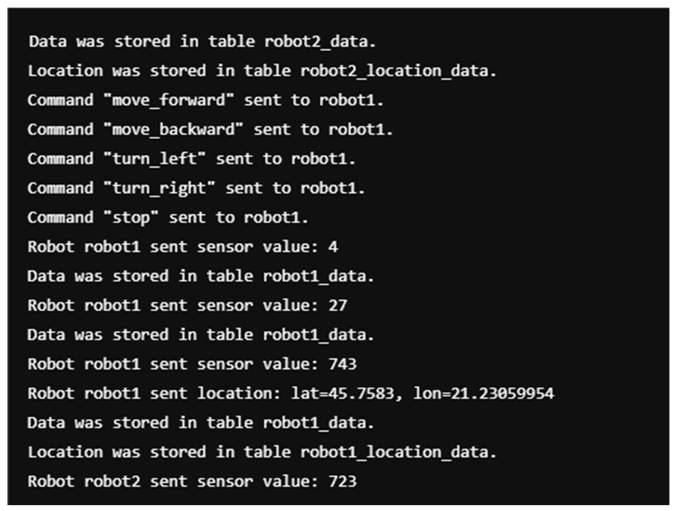
Figure 17.
Log of the Mobile Robot with ID Robot_1.
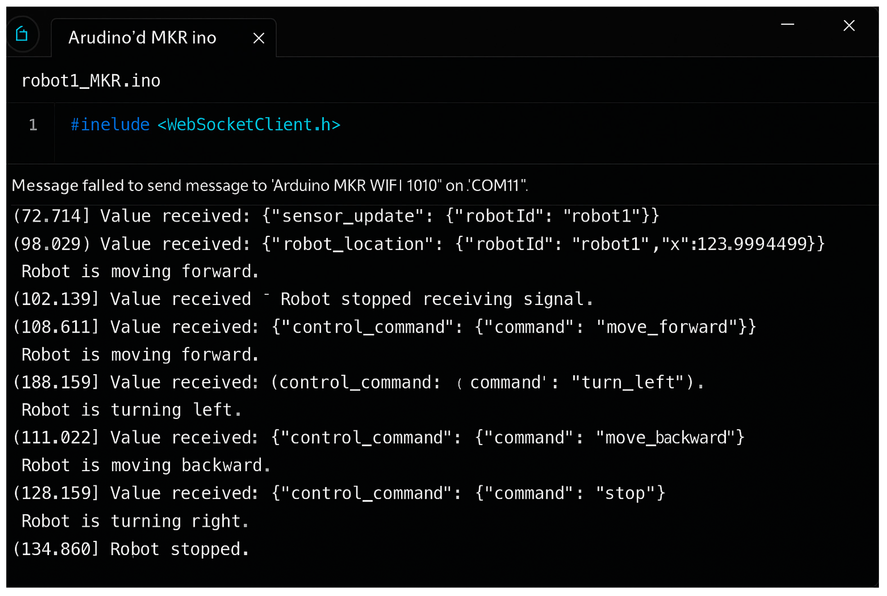
Figure 18.
Failover Strategy of the Robotic Network with Two Levels of Redundancy.
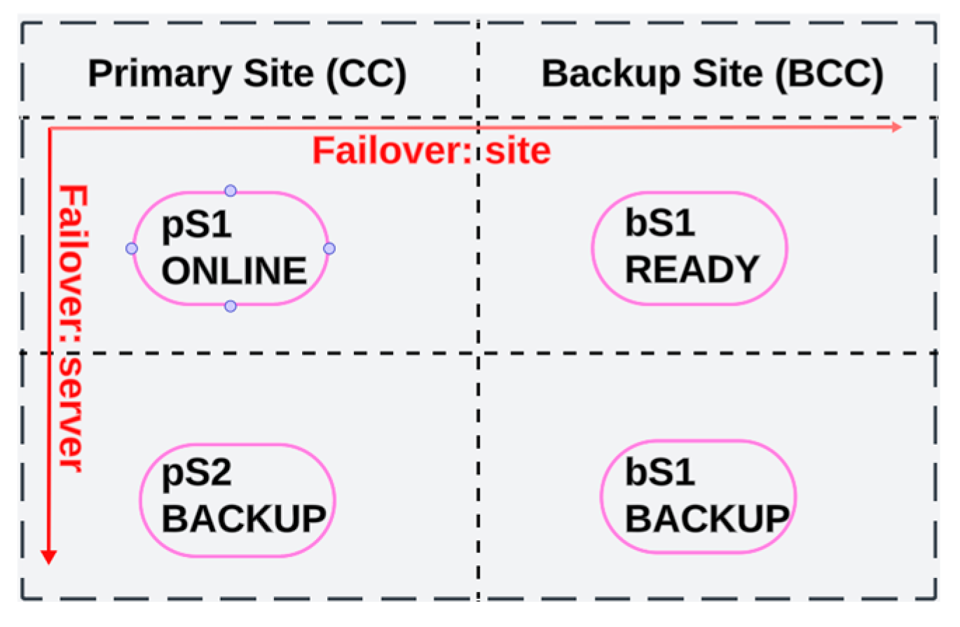
Figure 19.
Data Center Configuration and Connection Method.
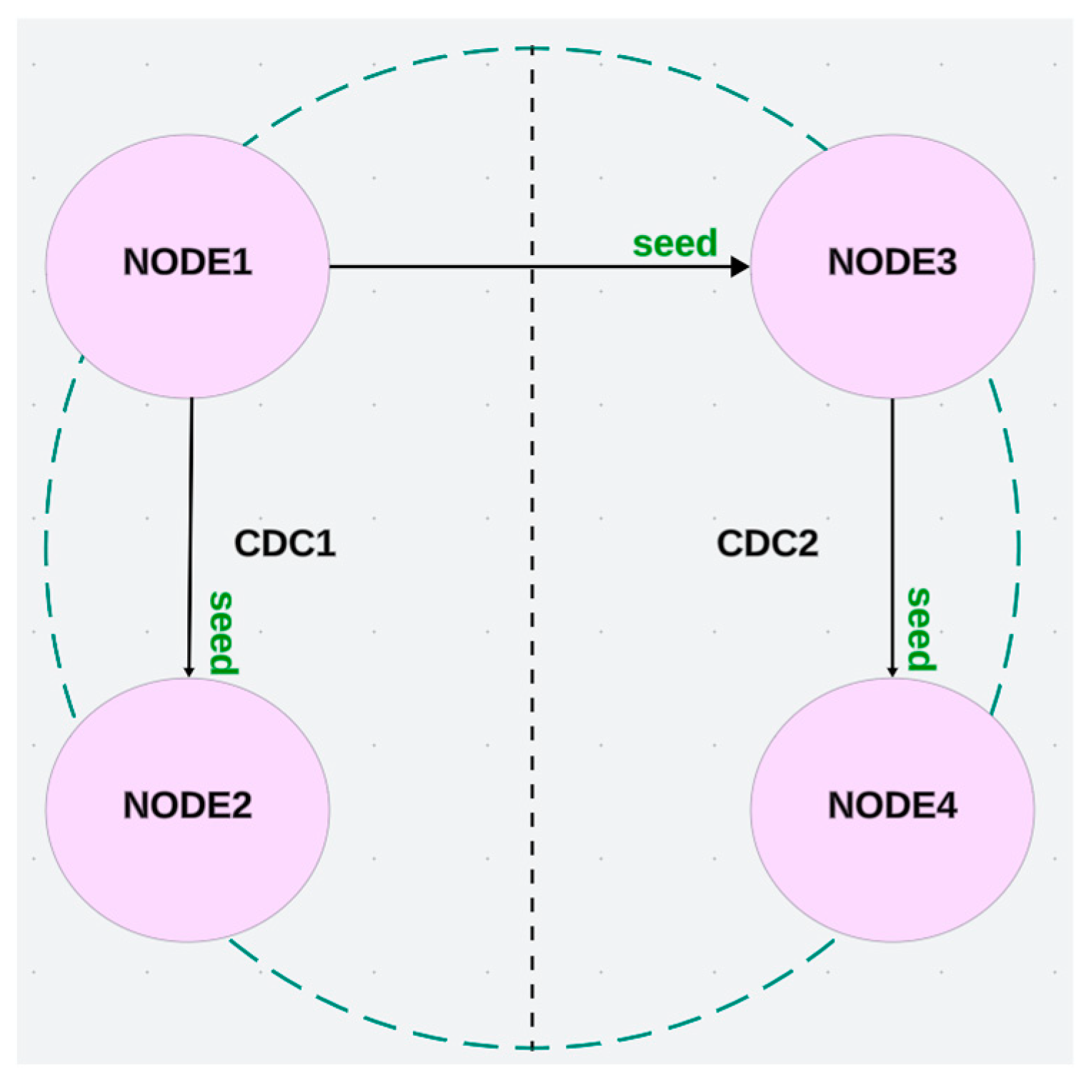

Table 1.
Definition of MAC Addresses and Microcontrollers of Mobile Robots for Network Integration.
| Client | MAC Address | Microcontroler |
|---|---|---|
| Robot_1 | 94:0D:7A:1B:5A:E0 | ESP 32 Wi-Fi Doit |
| Robot_2 | C0:49:EF:6B:EC:0C | Arduino MKR 1010 |
| Robot_3 | E0:23:AB:3B:ED:0A | Arduino MKR 1010 |
Disclaimer/Publisher’s Note: The statements, opinions and data contained in all publications are solely those of the individual author(s) and contributor(s) and not of MDPI and/or the editor(s). MDPI and/or the editor(s) disclaim responsibility for any injury to people or property resulting from any ideas, methods, instructions or products referred to in the content. |
© 2025 by the authors. Licensee MDPI, Basel, Switzerland. This article is an open access article distributed under the terms and conditions of the Creative Commons Attribution (CC BY) license (http://creativecommons.org/licenses/by/4.0/).
Copyright: This open access article is published under a Creative Commons CC BY 4.0 license, which permit the free download, distribution, and reuse, provided that the author and preprint are cited in any reuse.


