
Submitted:
25 June 2025
Posted:
26 June 2025
You are already at the latest version
Abstract
The National Research Council (NRC) of Canada is actively engaged in the development of an advanced autonomy system for the Bell 412 helicopter. This system's capabilities extend to executing complex missions, such as arctic resupply flights, where the helicopter autonomously performs tasks like takeoff with cargo, navigation while avoiding potential obstacles, and precise landing at its destination, all while minimizing the need for pilot intervention. The complexity of this autonomy system necessitates the inclusion of a high-level supervisory controller. This controller plays a critical role in monitoring mission progress, interacting with various system components, and efficiently allocating resources on board. Conventionally, supervisory controllers are embedded within monolithic programs, lacking transparent state flows and making modifications and system behavior testing a significant challenge. In our research, we present an innovative approach to develop supervisory controllers for autonomous rotorcraft. Leveraging the DEVS (Discrete Event System Specification) formalism and the Cadmium simulation engine, we effectively address the aforementioned challenges. Using the NRC's Bell-412 autonomy system as a comprehensive case study, we elucidate the entire development process for a state-based, event-driven supervisory controller for autonomous rotorcraft. This process encompasses modeling, implementation, verification, validation, testing, and deployment. It incorporates a simulation phase, in which the supervisor integrates with various components within a Digital Twin of Bell 412, and a real-time operations phase, where the supervisor becomes an integral part of the actual Bell 412 helicopter. Our method outlines the smooth transition between these phases, ensuring a seamless and efficient process.
Keywords:
DEVS
; autonomous flight
; supervisory controller
1. Introduction
The Canadian Vertical Lift Autonomy Demonstration (CVLAD) was a project aimed at developing an autonomy system for the Canada's National Research Council's (the NRC’s) Bell-412 Advanced Systems Research Aircraft (ASRA), equipped with advanced fly-by-wire capabilities [1]. This project's main goal was to conduct an arctic resupply mission where the helicopter will autonomously transport supplies, navigate through potential obstacles, and safely land at its destination, all while minimizing the need for manual pilot intervention.
Figure 1 offers a high-level component diagram of the ASRA, providing insights into the realm of autonomous helicopter flight. The ASRA comprises several distinct software modules, each playing an important role in the execution of autonomous missions. These modules encompass the Mission Planning Software (Element 1), the Autonomy Core (Element 2), the Autonomy Guidance (Element 3), and the LIDAR-based Landing Zone Evaluation module (Element 4).
The Mission Planning Software serves as the launchpad for setting up autonomous helicopter missions. It allows users to specify the take-off location, create flight plans, and define desired speeds and altitudes. After the mission is planned, it is transitioned to the Autonomy Core, which serves as the central hub and vital core of the CVLAD’s autonomy system. The Autonomy Core encompasses a Flight Control Computer (FCC), a Mission Manager, and the Supervisory Controller. The FCC takes on the role of communicating digital control commands to the helicopter's flight controls, managing automatic take-offs, waypoint navigation, and other essential functions. Simultaneously, the Mission Manager is entrusted with overseeing mission execution and communicating the autonomy's intent, including desired speed, heading, altitude, and more, to the Autonomy Guidance through visual cues. Once the helicopter reaches the landing leg, the Landing Zone Evaluation module selects the safest landing location. Upon determining the most suitable spot, the Autonomy Core executes an autonomous landing.
Given the complexity of the Bell 412 autonomous system, which comprises numerous subsystems, the necessity for a high-level supervisory controller, referred to as the "Supervisor" in this paper, becomes evident. In our scenario, the Supervisor is integrated as a key component of the Autonomy Core (Element 2, Figure 1), and plays a crucial role in ensuring the desired system’s state flow, overseeing the status of all the components, and managing resources within the helicopter. This is particularly essential since multiple subsystems may contend for shared resources, such as control authority - e.g., both the FCC and the pilot may seek to control the aircraft simultaneously.
There are numerous methods for the design and synthesis of supervisory controllers in industrial control systems. Such traditional techniques suffer from several drawbacks. Supervisory controllers are often monolithic programs with little separation of concerns applied, resulting in tight coupling between elements within the controller, as well as a lack of explicit states and transitions between states. Tight coupling between components of any system can lead to difficulty in performing modifications as well as extensive re-testing of the whole system when one small aspect of the program is changed. In general, the development of supervisory controllers may not consider future development: what starts as small procedural programs intended to fulfill a single purpose, may grow into complex and unmanageable systems where legacy code is intertwined with new features, such that any change, e.g., adding an extra state, might have far-reaching effects.
This research introduces an innovative approach to developing supervisory controllers that prioritize modifiability and transparency by harnessing Discrete Event System Specifications (DEVS) [2] in conjunction with the Cadmium library [3]. We demonstrate the practical application of this method by presenting a comprehensive development cycle for a supervisory controller tailored to the NRC's Bell-412. The process encompasses the entire autonomous helicopter mission, spanning from take-off to landing.
The supervisory controller was tested using the NRC's Bell 412 Digital Twin, and subsequently deployed onto the physical NRC Bell-412 helicopter. This journey encompassed a series of critical phases, commencing with model development, followed by verification in simulated time, the creation of interactive real-time test drivers, integration and testing with the NRC's Bell 412 Digital Twin, and deployment onto the actual helicopter, encompassing in-flight testing scenarios. The versatility of this method ensured that the supervisory controller we have developed can be effortlessly extended to incorporate detect-and-avoid and path-planning modules or facilitate straightforward integration onto other aircraft platforms.
The paper is organized as follows: Section 2 presents the background on supervisory controllers for autonomous systems. Section 3 explains the Supervisor development methodology, including the DEVS formalism. Section 4 focuses on the Supervisor model development and Section 5 focuses on the implementation of those models. Section 6 describes the interface development to integrate with other autonomy system components. Section 7 explains how the Supervisor was tested in simulation and deployed in the helicopter. Section 8 presents the conclusions and future work of this research.
2. Background
A discrete-event system (DES) is a discrete-state, event-driven system of which the state evolution depends entirely on the occurrence of asynchronous discrete events over time [4]. Discrete-event supervisory control introduced by [5] provides a discrete-event control mechanism that is executed by forcing or delaying specific events, to ensure the desired system’s state flow. In short, the control mechanism intends to prevent the system from entering an “unacceptable” state by speeding up or slowing down the state transitions. An example of an “unacceptable” state in the context of autonomous flight could be landing on an obstacle if a suitable landing location is not found, or running out of fuel while conducting an autonomous mission.
DES has been known for supervisory control for a long time; however, it only became popular in autonomous applications recently, due to the increasing complexity of these systems. When the system is relatively simple (i.e., because it performs only one task), a separate supervisory controller is redundant since any control mechanism can be executed by the inner-loop controller. On the other hand, when the system is complex and consists of several components that interact with each other, we need a high-level controller to monitor the inner states of each component, derive its own state, and make decisions accordingly. Such a controller can be essentially represented using a state machine that depicts the desired system’s state-flow to ensure each component executes in a timely manner. The desired states can be pre-programmed (desired state transitions are established “offline”) or derived in real-time (desired state transitions are established “online”).
Several examples of autonomous systems where a discrete-event controller ensures the desired state flow, are given below. In [6], the authors developed an autonomous system for driving in urban environments; they proposed the system structure and method of a self-driving car consisting of three main parts: perception, planning, and control. Each part was designed to recognize the real-time driving environment, make an action plan based on a finite state machine, and activate kinematic model-based control. In [7] the authors presented a systematic and mathematical design procedure for a hybrid state system-based controller for the intelligent mission management of an Unmanned Aircraft System. The proposed controller utilizes a discrete-event system flight executive based on a finite-state machine for high-level decision-making and a continuous-state controller for the lower-level autopilot. The flight executive and autopilot are integrated together to form the hybrid state controller. An example of supervisory control focusing specifically on the landing phase of a flight is described in [8]. The authors presented a visual servoing method for autonomous multi-rotor landing, where the behavior of the multirotor during the whole landing procedure was handled by a finite state machine.
An additional instance of a supervisory controller applied during the landing phase can be found in Borshchova's work [9]. Here, they developed a discrete-event supervisor that functioned alongside the inner-loop controller. In this research, the landing phase was represented as a Time Transition Model (TTM) and was tested in real-time to help the pilot and crew in handling exceptions during the landing phase. However, a significant challenge arose due to state explosion issues associated with the use of TTMs, making real-time implementation problematic.
Although there have been many advances in the field of DES, control engineers working on autonomous applications might lack experience with modeling and specification frameworks and software expertise in engineering design, resulting in monolithic programs with little separation of concern and tightly coupled components. Typically, the research documentation on supervisory controllers (including described above) does not give sufficient details of software implementation, making the reader speculate that their finite-state machines do not include states implicitly, but rather use “if-else” conditions to implement the desired logic. In general, the development of supervisory controllers does not seem to consider future development: what starts as small procedural programs intended to fulfill a single purpose, may grow into complex and unmanageable systems where legacy code is intertwined with new features, such that any change, e.g., adding an extra state, might have far-reaching effects. This makes it very challenging to transfer the supervisors onto different platforms, use various sub-components interchangeably, add other behaviors/models, and re-test the logic. From the CVLAD perspective, if the supervisory controller is not designed to support modularity from the beginning of its development cycle, it might be very challenging to modify the software to be able to apply it on other aircraft platforms, since the state machine will be significantly different (e.g., helicopters can hover over the desired landing point, while fixed-wing aircraft must join the glide slope).
To fulfill these gaps and address the challenges discussed above, we use the Discrete Event System Specification (DEVS) [2] and the Cadmium DEVS environment [3] to provide an alternate approach to building supervisors, focusing on modifiability and transparency. DEVS was chosen to model the CVLAD supervisory controller because it addresses the current challenges with supervisory controllers described earlier. DEVS is a hierarchical and modular modeling formalism that separates models and their execution engines. A target system can be built as a composite of atomic and coupled model components that can be linked to each other’s inputs and outputs allowing complex models to be built from simpler building blocks. The communication between models is performed through instantaneous occurrences where values are transmitted to and or received by a DEVS model. Modularity allows the behavior of large systems to be divided and modeled independently, increasing cohesion within components. The hierarchical nature of DEVS means that small components can be assembled to model much larger systems (such as CVLAD’s autonomy system). Modeling systems hierarchically and in a modular fashion allow sections of the model to change without affecting the whole model as well as partitioning behavior into logical blocks which can more easily be understood. This allows the models used in the simulation engine to be deployed on the helicopter without modification. Another advantage of DEVS is that the notion of “time” is built into the framework. Compared to less sophisticated and attractive at first glance methods like the QT library [10], DEVS allows for an easy approximation of complex dynamic discrete-event systems.
A graphical specification (DEVS-graphs) can be used as described in specifying DEVS models [11]. The main benefit of the DEVS-graphs notation is that it allows for greater interaction and clearer communication with stakeholders who may have limited knowledge of the formalisms, mathematical notation, and programming skills. Additionally, it assists the modeler with visualizing the system description. These benefits result in a developed system that accurately represents the stakeholders’ needs. Notations exist for modeling both atomic and coupled DEVS models. For atomic models (Figure 2), this notation is similar to a finite state machine: there are nodes (representing the states) connected by directed edges (representing the transitions), though several key extensions have been made.
As shown in Figure 2, the edges connecting nodes can be of two types: a dashed line to represent an internal transition or a solid line to represent an external transition. Some additional annotations are required to fully define the model: (1) each state must be labeled with an ID and a lifetime (LT) associated with the state; (2) each internal transition must be labeled with any outputs to ports and the associate output values that are generated when the internal transition fires; and (3) each external transition must be labeled with the input port and value pair that must be received in order for the transition to occur.
Coupled models can then be built up by connecting the inputs and outputs from atomic models to each other. It is useful in this circumstance to hide the structure of the atomic model inside a black box (Figure 3), and focus on the interfaces of the model when constructing coupled models. Atomic and coupled models are then connected together using arrows, the ends of which specify the sending or receiving port.
Although there are many DEVS simulators [13], we used Cadmium, a DEVS modeling and simulation engine that allows us to complete the whole development cycle (including embedded real-time execution) without modifying the original models. In Cadmium each atomic and coupled model are represented by a class, each of which can be instantiated into an object and then incorporated into larger coupled models. The implementation is in C++, and it can use external libraries to execute on a hardware target platform. Cadmium implements the abstract hierarchical simulation algorithm [14] for DEVS models.
Atomic models in Cadmium must contain: (1) a structure containing the input and output definitions for the ports, (2) a tuple with the input port types, (3) a tuple with the output port types, (4) a default constructor, (5) a function to handle internal transitions, (6) a function to handle external transitions, (7) a function to handle an internal and external transition occurring at the same time (confluence function), (8) a function to send outputs and (9) a function to manage the timing of each state. Coupled models in Cadmium must contain: (1) a structure containing the input and output definitions for the ports, (2) a Ports object with the input port types, (3) a Ports object with the output port types, (4) a Models object with the atomic/coupled models in the current coupled model, (5) an EICs object to define the external to internal couplings, (6) an EOCs object to define the internal to external couplings, and (7) a ICs object to define the internal couplings. Note that the classes for all objects are defined within the Cadmium simulator.
RT-Cadmium [15] allows executing Cadmium models in real time. The models are defined in the same way as in Cadmium, and the models execute based on the real-time clock instead of using virtual time. To connect with external devices, the I/O ports used for the DEVS models use an interface and drivers. The user models, the drivers and RT-Cadmium libraries are compiled to produce an executable that runs on different hardware platforms. A Modeling subsystem is connected to a Runtime and Messaging subsystems. The Main Runtime subsystem manages the overall aspects of the real-time execution and provides timing functions with microsecond precision. It controls atomic components, the top coupled component ports that are connected to the external environment, and uses the models to build a hierarchy. Finally, it spawns the main real-time task. The Runtime subsystem includes Simulators (that execute the atomic component functions in real-time), a Root Coordinator (that handles real-time event scheduling, and spawns Drivers), and Coordinators, in charge of message passing and scheduling of the subcomponents. The Messaging subsystem is in charge of transmitting messages between the different components in the Runtime subsystem, which makes the model execution advance (in virtual or real-time).
Other DEVS environments, both for simulation and real-time execution include [16], as well as [6], who defined real-time models using the DEVS framework. In [17], the authors showed how to reuse models developed in different simulation engines by interfacing E-CD++ [18] and PowerDEVS [19]. PowerDEVS provides a method to model hybrid systems and execute RT models. Action-Level Real-Time DEVS [20] is used to model Network-on-Chip systems. One of the advantages of RT-Cadmium is that the models can run on bare hardware, without the need of an operating system or other middleware, making modular classes simple to be reused.
3. Methodology
We propose to use a spiral project lifecycle with evolutionary prototypes [21] to develop supervisory controllers. Alongside the proposed spiral lifecycle, decomposing the supervisory controllers into smaller modular components allows for easier management of individual work items. Each modular sub-component of the supervisory controller can be iterated upon until each is fully verified and ready for integration. Figure 4 shows a diagram of the lifecycle and demonstrates how validation is the key driver in iterating upon a given work item, ensuring the final deliverables’ acceptance.
First, the work items that will combine to form the supervisory controller need to be identified. These work items can be identified through different methods: initially from elicited requirements [22] and existing programs, then later through decomposition of supervisory controller components into smaller encapsulated and decoupled subcomponents. The use of DEVS greatly helps in the identification of work items as models that grow too complex or lose encapsulation of one specific behavior can be decomposed hierarchically into interacting sub-models.
Secondly, requirements are gathered for the identified work item. Requirements can be identified through elicitation from stakeholders or domain experts, in the case of new programs, or can come from the partitioning of a larger model’s requirements into sub-models [22]. Requirements for a work item are not necessarily static and can increase in fidelity with each iteration.
With an initial set of requirements, a DEVS Graph prototype should be created that satisfies the understood requirements [21]. DEVS Graphs is an invaluable tool in prototyping DEVS models. Due to the illustrative nature and ample tool support for creating diagrams, DEVS graphs can be drafted rapidly compared to other formal specification methods. By increasing the speed at which prototypes can be produced, the time between prototype iterations is reduced.
Once a DEVS Graph prototype is defined, the prototype can be presented to stakeholders for validation [23]. By examining the prototype with the stakeholders, the behavior can be easily explained and validated against the stakeholders’ requirements [22]. Small adjustments to the DEVS Graph can be made in real-time as the prototype is validated for rapid iteration that is informed by stakeholder expertise.
If larger modifications to the prototype are required, the prototype can be revised, and then presented to stakeholders later. This process of modification and re-validation should be repeated until all requirements are met. It is important to remark that all this process is done without the need to implement any part of the software.
Once the stakeholders approve the prototype, the DEVS Graph can be implemented directly into a C++ class using the Cadmium library [3]. As the DEVS Graph prototype is already a direct representation of the DEVS model and Cadmium provides a one-to-one implementation of DEVS models in C++, the implementation of prototypes into classes is trivial as it is a direct translation of the DEVS Graph into C++ code.
After we implement the prototype using Cadmium, the implementation should be unit tested [23]. Test drivers can be constructed using Cadmium to harness onto the implementation and iteratively run through a test suite. Test cases for the implementation can be derived from the stated requirements and from the DEVS Graph prototype. After running the test suite, trajectories and events must be analyzed to verify that the model exhibited behavior that met all the stated requirements. Additional validation with stakeholders can occur at this point to ensure that the implementation does not miss any requirements.
Upon successful unit testing, the implementation can be integrated into any larger Cadmium models. If the model was incorporated into a multi-level coupled model, integration testing should be conducted recursively on all higher-level models. For each higher-level model, any existing test cases should be reviewed and modified to consider the new model's behavior. All test drivers should be re-run and subsequent faults are to be identified and addressed in all affected models.
After the new model is fully verified using integration and unit testing, the model can be integrated into the supervisory controller, at which point a validation demonstration can be performed. By validating the supervisory controller alongside stakeholders, erroneous or missing behaviors in the system as a whole can be identified and remedied in further iterations or work items.
The above process for the development of supervisory controllers presents several benefits. Through regular validation of evolutionary prototypes against stakeholder requirements throughout the lifecycle, concerns regarding missing or previously unknown requirements can be quickly addressed before development proceeds too far [21]. By testing new models at each level, the unexpected consequences of integration can be reduced and faults in model design and implementation can be addressed quickly [23]. By iterating on work items until a final satisfactory validation is performed, it can be guaranteed that the behavior of the supervisory controller was incrementally improved by the development.
It is important to remark that the supervisory controller we developed using this process was the same implementation that was deployed into the specific application. As the Cadmium DEVS models could be run in simulated or real-time as well as with simulated or real stimuli, the models developed using this process could be deployed directly onto the helicopter. To develop the application-specific interfaces for the Bell-412 autonomy system, a similar process was used with minor variations as requirements stemmed less from stakeholder requirements and more from previously defined interfaces that the Supervisor had to adhere to. It is important to remark that the interfaces were independent from the Supervisor: shall the interface of a component change, the supervisor does not need to be modified, just the interface.
4. Supervisor DEVS Model Development
In this section and the rest of the paper, we show a case study of how the methodology is applied. We developed a supervisory controller for the entire autonomous mission, from take-off to landing.
As stated in the introduction, a helicopter equipped for autonomous flights has several hardware and software components. Before a flight mission starts, the mission planner designates the intended path of autonomy system (waypoints), as well as speeds, altitudes etc. The mission planner also designates the circular area in which it is intended that the aircraft will land - this is called the Planned Landing Point (PLP). Once the aircraft approaches the PLP, the LIDAR-based landing zone evaluation system will identify Landing Points (LPs) within the PLP radius. LPs are regions large enough for the helicopter to land in and are clear of obstacles. Multiple LPs might be found by the LIDAR, so for how long LPs are sought after and which LPs are “accepted” will be the responsibility of the Supervisor. The Supervisor will also receive inputs from the FCC, mission manager, pilot, and aircraft, and will determine whether the FCC should be ordered to land the helicopter at the received LP location, or to hand control over to the pilot, if no suitable landing point is found.
The following sections describe the models for the CVLAD Supervisory Controller and its sub-models.
4.1. Supervisor Coupled Model
The purpose of the Supervisor coupled model (Figure 5) is to manage the autonomous flight by receiving signals from external systems (such as the FCC, mission planner, and mission manager), processing those signals to advance the state of the system and notifying those systems back with the actions to be taken. A preliminary supervisory controller just for the landing phase of the flight was already described in [24].
To fully encapsulate all the behavior of the CVLAD Supervisory Controller, the Supervisor coupled model was decomposed into 3 sub-components Takeoff, On Route, and Landing. Each subcomponent encapsulates a phase of a mission:
- The Takeoff model is used to initialize the mission, verify the status of the autonomy system prior to takeoff, and to alert the other Supervisor sub-components that the mission has started.
- The On Route model facilitates the forwarding of mission items (e.g., waypoints) to the flight control computer as they are reached throughout the flight.
- The Landing model defines the behavior of the Supervisor from the receipt of the last mission item until the helicopter has landed or handed control to the pilot, through several trajectories based on the availability of safe landing points.
The Supervisor coupled model (Figure 5) uses 8 input ports and 16 output ports. The input ports along with a description are presented in Table 1 and the output ports in Table 2.
In the following section, we discuss the definition of the Landing Point Manager atomic model, which serves as an illustrative example model. Note that all the atomic models in the system are defined in a similar way.
4.2. Landing Point Manager Atomic Model
The Landing Point Manager atomic model depicted in Figure 6 serves the purpose of receiving, evaluating, and deciding upon Landing Points (LPs). It is responsible for managing LP acceptance or rejection and making informed decisions in situations where a suitable LP cannot be located.
The atomic model uses thirteen states to represent this behavior: (1) IDLE, (2) WAIT_FOR_LANDING_PHASE, (3) REQUEST_STATE_PLP, (4) GET_STATE_PLP, (5) START_LZE_SCAN, (6) LZE_SCAN, (7) HANDOVER_CONTROL, (8) PILOT_CONTROL, (9) REQUEST_STATE_LP, (10) GET_STATE_LP, (11) NOTIFY_LP, (12) LP_APPROACH, (13) LP_ACCEPT_EXP. The model is initialized in the IDLE state. It remains IDLE state until the start_mission is received, at which point it transitions to the WAIT_FOR_LANDING_PHASE state.
The atomic model has two main trajectories. The first trajectory occurs when the PLP is achieved (a signal is received on the PLP_ach input port) before an LP is received. After the PLP is achieved the Landing Point Manager will request the aircraft state (position, attitude, velocities etc.). Knowing the aircraft's state, the model requests for the helicopter to be stabilized, so the landing zone can be evaluated. If an LP is not received during the scan of the landing zone, the model will hand over control of the aircraft to the pilot (transition to the state HANDOVER_CTRL). If an LP is received while scanning the landing zone (state START_LZE_SCAN), the model will join the second trajectory.
The second trajectory occurs when an LP is received (a signal is received on the LP_recv input port) before the PLP is achieved or if the landing zone evaluation successfully identifies an LP (state START_LZE_SCAN). After an LP is received, the model then requests the aircraft state and starts the LP_APPROACH timer. This timer allows new valid LPs to be considered for a defined duration. If the received LP is valid (located far enough from the previous LP), the model sends a new LP output using the LP_new port. Once the LP_APPROACH timer expires, the system will transition to an end state (LP_ACCEPT_EXP) and will not allow any further updates to the LP, while indefinitely waiting for the pilot to take control (a signal sent on an output port pilot_handover). Further to that, pilot can take control of the helicopter at any state (a signal received on an input port pilot_takeover).
5. Implementing the Supervisor
After developing the DEVS models, a simulation of the Supervisor DEVS models was implemented using the Cadmium library as well as the real-time version of Cadmium. Using the DEVS models developed earlier, test drivers were created to simulate the models for verification and validation of the behavior by the NRC experts. An evolutionary prototype life-cycle was used to iterate upon the implementation, adding more functionality and implementing stubbed components with each cycle. First, a simulation of the Supervisor was created using Cadmium for verification and validation of the DEVS atomic and coupled models. The same models were then used, without modification, using a real-time version of Cadmium removing the need of performing verification and validation again. Each C++ model implementation was simulated using a test driver, then simulation results were inspected for verification and validation.
5.1. Landing Point Manager Atomic Model
The Landing Point Manager atomic model was implemented by translating the specification in DEVS Graphs into a C++ class that could be used by the Cadmium simulation library as shown in Figure 7.
The input and output ports of the model are defined by the input_ports and output_ports namespaces. The model structure includes a set of states (an enumeration) used to define the state variable state_type. The initial state of the model is IDLE. The internal_transition method uses a case statement based on the current state, as seen in Figure 7. The external transition method checks the inputs of the model and then chooses the transition based on the input received and the current state (also defined in Figure 7). The outputs from the model were defined based on the current state: message bags were constructed and sent to the output ports with information to be sent to other models within the Supervisor as well as the pilot. Finally, the time advance function for the model was defined by returning a TIME given the current state of the model using a switch-case statement. The remaining atomic models as well as the interface atomic models were defined in a similar manner based on the DEVS Graphs specification.
5.2. Supervisor Coupled Model
The Supervisor coupled model was implemented using the sub-models previously defined in C++ as well as the structure conveyed by the graphical specification as shown in Figure 8.
The sub-models of the Supervisor were built using the make_dynamic_atomic_model and make_shared functions provided by Cadmium; then, references to each model were given in the submodels structure. Once each sub-model was initialized, the couplings were defined: the connections between inputs to the Supervisor and the inputs of sub-models were defined in the eics structure, the connections between outputs of sub-models and Supervisor outputs were defined in the eocs structure, and the connections between outputs of sub-models and the inputs of other sub-models were defined in the ics structure. Other coupled models inside the Supervisor were defined in a similar manner.
6. Interface Development
To integrate the Supervisor with the rest of the autonomy system, interfaces needed to be created. Most of the aircraft’s autonomy system communicates using the User Datagram Protocol (UDP), however the Supervisor was also required to interface through other means as well. To retrieve aircraft state information (e.g., latitude, longitude, altitude, airspeed, pitch, etc.) an interface to a shared memory segment populated by the aircrafts avionics was required. In addition to communicating with autonomy system components using UDP, another method with more reliability in packet delivery was necessary. To avoid the overhead associated with using a TCP connection, a simple library was developed to deliver UDP packets reliably using the stop-and-wait automatic repeat request (ARQ) protocol [25]. Using the library, a reliable interface for communication with the Supervisor was created.
6.1. UDP Output Interface
To facilitate the communication between events generated by the Supervisor and the autonomy system components, a DEVS atomic model was created: the UDP Output model (Figure 9).
The UDP output atomic model was used to translate an event generated by the Supervisor and send it as a UDP packet to a specified address and port. The content was sent to a predetermined network address and port instead of an external output port. The UDP Output model was designed to send a DEVS event from the Supervisor as a UDP packet to a singular autonomy system component. Multiple UDP Output models could then be combined to notify all the necessary components when a DEVS event occurs, for example, the pilot display and Mission Manager when the mission complete output is generated.
6.2. Shared Memory Interface
Onboard the aircraft, a shared memory segment is populated with the current state of the aircraft. To access the current state of the aircraft a model was required to access the shared memory segment. To avoid the overhead of polling the segment and supplying a constant stream of aircraft states, it was determined that the model would accept a request for the current aircraft state from the Supervisor, after which it would access the shared memory segment, and provide an event containing the current aircraft state, as is shown in Figure 10.
6.3. Reliable UDP Interface
Parallel to the development of the Supervisor, the requirement for reliable delivery of certain events across the whole autonomy system was identified, so a reliable UDP library was developed for use with the Supervisor. As most network communication within the autonomy system uses UDP and the overhead of TCP was to be avoided, a library was created to reliably deliver packets over UDP. The library was implemented using the Boost ASIO C++ library [26] and utilized the stop-and-wait ARQ protocol [26] to ensure that packets were delivered reliably and without replication. As the library would no longer be compatible with all UDP interfaces (through the introduction of a new upper layer packet header), new interface models were required so the Supervisor could receive events over Reliable UDP (RUDP) as well as send events as well.
The Supervisor UDP Input model (Figure 11) was used to receive RUDP packets, demultiplex the packet to an input port of the Supervisor based on a header field, then convert the packet into an event that can be understood by the Supervisor. The input model was designed to connect to each input of the real-time Supervisor model so the Supervisor could reliably receive UDP packets from the mission manager component.
The RUDP Output atomic model (Figure 12) was used to translate an event generated by the Supervisor and send it as an RUDP packet to a specified address and port using the RUDP library. The model functions in much the same way as the UDP Output model by translating a DEVS event into a packet exchanged over the network.
7. Supervisor Model Verification and Deployment
Verification of the Supervisor was conducted throughout the project: the graphical specification of the DEVS models were visually tested with the help of the CVLAD team, then the simulated models were verified using simulated-time, interactive real-time test drivers, Bell 412 Digital Twin, and then through actual flight tests.
Atomic models were tested to confirm that correct transitions were made given certain inputs and time advance functions, and that outputs were generated at the correct transition. We used white box testing to evaluate the control flow of atomic models. The tests were written to evaluate the whole behavior of the system and cover all possible evolution paths. Black box testing was used to verify the coupled models. Additionally, coupled models were built by linking together atomic models already verified through white box testing.
The graphical specifications and description of DEVS atomic and coupled models (including its purpose and behavior) were provided to the stakeholders for feedback to meet the requirements. Interactive test drivers were also used for validation of the Supervisor by stakeholders. A command line Supervisor test driver allowed researchers to test if all required behavior was present as well as validate that the outputs were generated at the right time. Finally, testing on Bell 412 Digital Twin helped de-risking before taking the software into the flight test.
Due to confidentiality constraints around the Bell 412 Digital Twin, this paper only presents testing in simulated time as well as actual deployment on Bell 412.
7.1. Testing in Simulated Time
Test drivers were created to test the behavior of each simulated atomic and coupled DEVS model. Each test driver consisted of an input reader (provided by the Cadmium library) coupled to each input of the model under test to read input events. The state changes and events were then recorded using loggers provided by Cadmium. The logs of each simulation run could then be analyzed to determine whether the model under test was exhibiting the required behavior.
Figure 13 shows an example test driver (for the Landing Point Manager atomic model shown in Section 4.2 and implemented in Section 5.1). The model consists of seven input readers, named as the port the reader is coupled to with “ir_” (input reader) prefixed.
The test cases for the Landing Point Manager test driver were derived from a transition tree presented in Figure 13. The transition tree was created starting at the initializing node in Figure 13 (i.e., ID). From the ID state, we defined one node for WAIT_FOR_LANDING_PHASE (WLP in figure 13). From WAIT_FOR_LANDING_PHASE four new nodes were created (one for each transition) for REQUEST_STATE_LP (RSL in Figure 13), WAIT_FOR_LANDING_PHASE (WLP in Figure 13), PILOT_CONTROL (PC in Figure 13), and REQUEST_STATE_PLP (RSP in Figure 13). If a node represented a final state in the atomic model or it was already in the tree, the node was marked as terminating with an “X”. This process was repeated from the newly created nodes until there were no transitions left in the atomic model.
Using the transition tree criteria, each path from the initialization node was tested to a terminating node denoted (defined by the “X” under the node). It is important to remark that to test transitions occurring from an input in a state that has a zero time advance it was required to start the model in that state to test it. For example, in Figure 14, to test the path from WLP to PC the test driver would initialize model in the WLP state and have an event at time equals zero to transition to PC. This method only tested the defined transitions. To accomplish complete coverage of the models the sneak paths also needed to be tested. This means that each state in an atomic model needed to be tested for all the inputs that would not cause it to transition. This was done to confirm that no undefined behavior could occur.
Once each test case was defined, the test driver was used to simulate the model. Table 3 shows test cases for the Landing Point Manager atomic model. The scenario shows the model receiving an input at time 00:00:02:000 on the input port start_mission, indicating that the system must become active. At 00:00:10:000, a new input was received on plp_ach port indicating that the planned landing point was achieved. At 00:00:12:000, an input on the aircraft_state port was received notifying the system of the aircraft's current state. After the simulation was completed, log files of events and state transitions became available. A sample of the log for the Landing Point Manager test driver is shown in Table 4, it includes the time of an event, the state of each atomic model at the time, the port on which the output generated (if any), and the value of the output. In Test 0, the model started in the IDLE state. Once the model received an input on the start_mission port at time 00:00:02:000 (Table 3), it transitioned to the WAIT_FOR_LANDING_PHASE state. At time 00:00:10:000 (Table 3) the model received the plp_ach signal and transitions to the REQUEST_STATE_PLP state. As the time advanced, it immediately changed state to GET_STATE_PLP and generated an output in the o_request_aircraft_state output port with the value 1, the system then waited for the aircraft state. The rest of the log can be interpreted in a similar way.
7.2. Deployment on Bell 412
Finally, the Supervisor underwent extensive testing on the NRC’s Digital Twin, replicating the Bell 412 autonomy system. Simulation testing was conducted as a necessary precaution since any error during autonomous flight could lead to catastrophic consequences. Following successful validation on the Digital Twin, the Supervisor was then subjected to real-flight testing on the NRC’s Bell 412 autonomy system, under the supervision of a pilot. This autonomy system comprises several software components distributed across different hardware and interconnected through a LAN, as illustrated in Figure 15. These components include:
- Flight Control Computer (FCC): Responsible for inner/outer-loop autonomy state control, the FCC sends digital commands to the helicopter's flight controls and manages the aircraft's trajectory during flight, executing tasks such as automatic take-off and waypoint navigation.
- Mission Planner: Utilizing a custom NRC version of QGroundControl [27], this software configures autonomous helicopter missions, specifying take-off locations, creating flight plans, and defining speeds and altitudes between waypoints.
- Mission Manager: NRC-developed software that oversees the helicopter's flight path, manages mission execution, and conveys the autonomy's intent (desired speed, heading, altitude, etc.) to the autonomy guidance module via visual cues.
- Landing Zone Evaluation Module: Comprising the Peregrine LIDAR system [28], this module generates coordinates for the most suitable landing location within the designated landing area.
- Autonomy Guidance: This pilot display software communicates the autonomy's intent and reference points to the pilot.
- Aircraft Inertial Navigation System (INS): Located within the aircraft, this module provides information about the aircraft's state, including roll, pitch, yaw, position, speed, and more, to the other autonomy components.
- Supervisory Controller: Serving as a high-level supervisory controller, it monitors the state of the autonomy system and its sub-systems.
As depicted in Figure 15, the Supervisor, Mission Manager, and Mission Planner share the same hardware (Bell 412 Engineering Station), while the FCC, Autonomy Guidance, INS, and Landing Zone Evaluation module are housed on separate hardware units distributed across the LAN. Due to confidentiality constraints, this paper cannot disclose further details about the Bell 412 autonomy components. However, a video showcasing an autonomous flight demonstration using the Supervisor described herein can be accessed via the following link: https://www.youtube.com/watch?v=dQqOMaNegEc.
Notably, this configuration mirrors the setup in the Digital Twin used for testing before transitioning to actual flight. The primary distinction is that all Digital Twin components reside on the same computer.
8. Conclusions and Future Work
In this work, we present a method to develop supervisory controllers. This method has been exemplified by defining the supervisory controller for the NRC’s Bell 412 autonomy system. The model (and therefore, the final software) was developed using a formal method, in this case, the DEVS formalism and DEVS-Graph notation. The graphical models were then used to implement the atomic and coupled models in C++, and Cadmium was used to develop the Supervisor. The models were validated using the graphical specifications and verified using Cadmium in both simulation and real-time testing suites. Since the project life cycle followed the spiral model, the system was rapidly prototyped and tested after every update.
The use of DEVS as a formalism to develop and design supervisory controllers for aircraft is novel within the aerospace field. Supervisory controllers developed using common industry techniques often suffer from several issues leading to difficulty in maintenance, future development, and testing. DEVS offers the ability to effectively apply separation of concerns in the development of controllers, such that behavior is compartmentalized. Subsets of the supervisory controller behavior can then be expanded upon in future (e.g., adding detect-and-avoid, path planning, etc.) without impacting the entire system and unit tested separately before being integration tested.
When analyzing the integration of the Supervisor with the rest of the autonomy system, the issue of cause-effect problems was encountered. In the cases, when transport time for messages was low, for example over a bus in a single hardware, there was very little chance that messages were received out of order. In other cases, when the transport time of messages was high due to source and destination components being located on different hardware, there were times when the messages arrived in a different order to which they were sent, or the packet was lost, resulting in the autonomy system exhibiting incorrect and unexpected behavior. Proving a solution to the cause-effect problem is now being addressed by the research team by developing a reliable communication protocol, called “CVLAD link, or CLINK”, and a health monitoring system, which ensure no important messages are dropped or out of order.
It is crucial to emphasize that in tackling the aforementioned challenge, there is no necessity for modifications to the supervisory controller, and our focus should only be on enhancing the reliability of communication interfaces.
Author Contributions
James Horner – software, writing, original draft preparation. Tanner Trautrim – software, writing, original draft preparation. Cristina Ruiz Martin – methodology, conceptualization, writing, review and editing. Iryna Borshchova – methodology, conceptualization, writing, review and editing. Gabriel Wainer – methodology, supervision, review and editing.
Funding
This research received no external funding
Conflicts of Interest
The authors declare no conflicts of interest.
Abbreviations
The following abbreviations are used in this manuscript:
| NRC | National Research Council |
| DEVS | Discrete Event System Specification |
| CVLAD | Canadian Vertical Lift Autonomy Demonstration |
| ASRA | Advanced Systems Research Aircraft |
| FCC | Flight Control Computer |
| DES | Discrete-Event System |
| TTM | Transition Time Model |
| PLP | Planned Landing Point |
| LP | Landing Point |
| UDP | User Datagram Protocol |
| TCP | Transmission Control Protocol |
| ARQ | Automatic Repeat Request |
| RUDP | Reliable User Datagram Protocol |
References
- Colucci, F. 2022. “Supervised Autonomy, Step-by-Step”. Vertiflite, Fort Worth, USA: Vertical Flight Society.
- Zeigler, B. P., T. G. Kim, and H. Praehofer. 2000. Theory of Modeling and Simulation: Integrating Discrete Event and Continuous Complex Dynamic Systems. New York: Academic Press.
- Belloli, L., D. Vicino, C. In Ruiz-Martin, and G. Wainer. 2019. “Building Devs Models with the Cadmium Tool”. In Proceedings of the 2019 Winter Simulation Conference, edited by N. Mustafee, K.H.G. Bae, S. Lazarova-Molnar, M. Rabe, C. Szabo, P. Haas, and Y.-J. Son, Piscataway, New Jersey: Institute of Electrical and Electronics Engineers, Inc. 45-59. [Google Scholar]
- Wonham, W.M., K. Cai, and K. Rudie. 2017. “Supervisory Control of Discrete-Event Systems: A Brief History–1980-2015”. IFAC-PapersOnLine 50(1): 1791-1797.
- Ramadge, P. J.; Wonham, W. M. (87). "Supervisory Control of a Class of Discrete Event Processes". SIAM Journal on Control and Optimization. 25 (1): 206–230. 19 January. [CrossRef]
- Song, H. , and T. Kim. 2005. “Application of Real-Time DEVS to Analysis of Safety-Critical Embedded Control Systems: Railroad Crossing Control Example”. Simulation 81(2): 119–136. [CrossRef]
- Hejase M, Oguz AE, Kurt A, Ozguner U and Redmill K. “A Hierarchical Hybrid State System Based Controller Design Approach for an Autonomous UAS Mission” 16 Conference: 16th AIAA Aviation Technology, Integration, and Operations Conference. 20 June. [CrossRef]
- Delbene A, Baglietto M, Simetti E. Visual Servoed Autonomous Landing of an UAV on a Catamaran in a Marine Environment. Sensors (Basel). 2022 ;22(9):3544. 6 May. [CrossRef] [PubMed] [PubMed Central]
- Borshchova, I. 2017. Vision-based Automatic Landing of a Rotary UAV. PhD Thesis. St. John’s: Faculty of Engineering and Applied Science. Memorial University of Newfoundland.
- Qt, “QStateMachine class,” Qt Documentation. [Online]. Available: https://doc.qt.io/qt-6.2/qstatemachine.html. [Accessed: 13-Jun-2025].
- Praehofer, H. , and D. In Pree. 1993. “Visual Modeling of DEVS-based Multiformalism Systems Based on Higraphs”. In Proceedings of the 1993 Winter Simulation Conference, edited by G.W. Evans, M. Mollaghasemi, E.C. Russell, and W.E. Biles, Piscataway, New Jersey: Institute of Electrical and Electronics Engineers, Inc. 595–603. [Google Scholar]
- Wainer, G. A. 2009. Discrete-Event Modeling and Simulation: A Practitioner's Approach. Boca Raton: CRC Press.
- Van Tendeloo, Y. , and H. Vangheluwe. 2017. “An Evaluation of DEVS Simulation Tools”. SIMULATION 93(2):103-121. [CrossRef]
- Zeigler, B.P., A. C. Chow, and D.H. Kim. 1994. “Abstract Simulator for the Parallel DEVS Formalism”. Proceedings of the Fifth Annual Conference on AI, Simulation, and Planning in High Autonomy Systems. 7th – 9th 94, Gainesville, Florida, USA, 157-163. 19 December.
- Niyonkuru, D. , and G. Wainer. 2021. “A DEVS Based Engine for Building Digital Quadruplets”. Simulation 97:7 485-506. [CrossRef]
- Hu, X. , and B. Zeigler. 2005. “Model Continuity in the Design of Dynamic Distributed Real-Time Systems”. 8: IEEE Transactions on Systems, Man, and Cybernetics - Part A: Systems and Humans 35(6). [CrossRef]
- Moallemi M., S. Jafer, A. In S. Ahmed, and G. Wainer. 2011. Interfacing DEVS and visualization models for emergency management. In Proceedings of the 2011 Symposium on Theory of Modeling & Simulation: DEVS Integrative M&S Symposium (TMS-DEVS '11). Society for Computer Simulation International, San Diego, CA, USA; 111–116. [Google Scholar]
- Wainer, G.A. , and E. Glinsky. 2004. “Model-Based Development of Embedded Systems with RT-CD++.” 10th IEEE Real-Time and Embedded Technology and Applications Symposium (RTAS), 25th-28th 04, Toronto, ON, Canada. 20 May.
- Bergero, F. , and E. Kofman. 2011. “PowerDEVS: a Tool for Hybrid System Modeling and Real-Time Simulation”. Simulation 87(1–2): 113–132. [CrossRef]
- Gholami S, and H. Sarjoughian. 2017. “Action-Level Real-Time Network-On-Chip Modeling”. 2: Simulation Modelling Practice and Theory 77.
- Hughes, B. and M. Cotterell, “Selection of an Appropriate Project Approach,” in Software Project Management, London u.a.: McGraw-Hill, 1999, pp. 64–70.
- van Lamsweerde, “Domain Understanding and Requirement Elicitation,” in Requirements engineering: From system goals to UML models to software specifications, Chichester, UK: John Wiley, 2009, pp. 61–87.
- Ammann P and, J. Offutt, Introduction to software testing. Cambridge: Cambridge University Press, 2017.
- J. Horner, T. J. Horner, T. Trautrim, C. Ruiz-Martin, I. Borshchova, and G. Wainer, “Winter Simulation Conference 2022,” in Proceedings of the Winter Simulation Conference 2022, pp. 441–452.
- Tanenbaum S, N. I. Feamster, and D. Wetherall, Computer Networks. London: Pearson, 2021.
- Kohlhoff C, “Boost ASIO Documentation,” Boost C++ libraries, 08-Dec-2022. [Online]. Available: https://www.boost.org/doc/libs/1_81_0/doc/html/boost_asio.html. [Accessed: 01-Jun-2025].
- DroneControl, 2019, QGroundControl, Available at: http://qgroundcontrol.com, [Accessed: 01-Jun-2025].
- Aaron Aupperlee, 2017, The Pittsburgh Tribune-Review, Available at: https://www.govtech.com/fs/airbus-partners-with-near-earth-autonomy-to-ensure-self-flying-cars-can-land-safely.html#:~:text=A%20laser%20scanner%20developed%20by%20Near%20Earth%20Autonomy,cars%2C%20and%20for%20slopes%20that%20could%20complicate%20landing. [Accessed: 01-Jun-2025].
Figure 1.
CVLAD autonomy system overview.
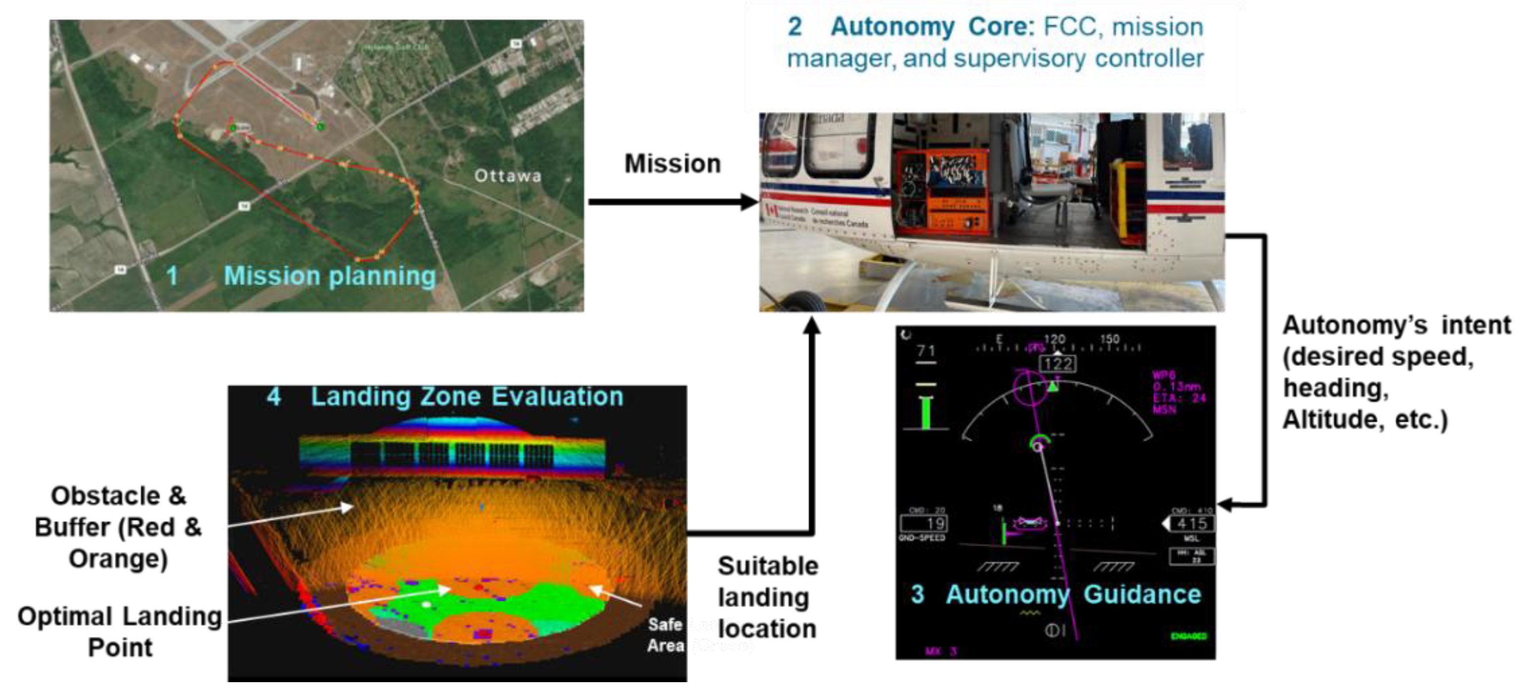
Figure 2.
DEVS atomic models using DEVS-Graphs [12].
Figure 2.
DEVS atomic models using DEVS-Graphs [12].
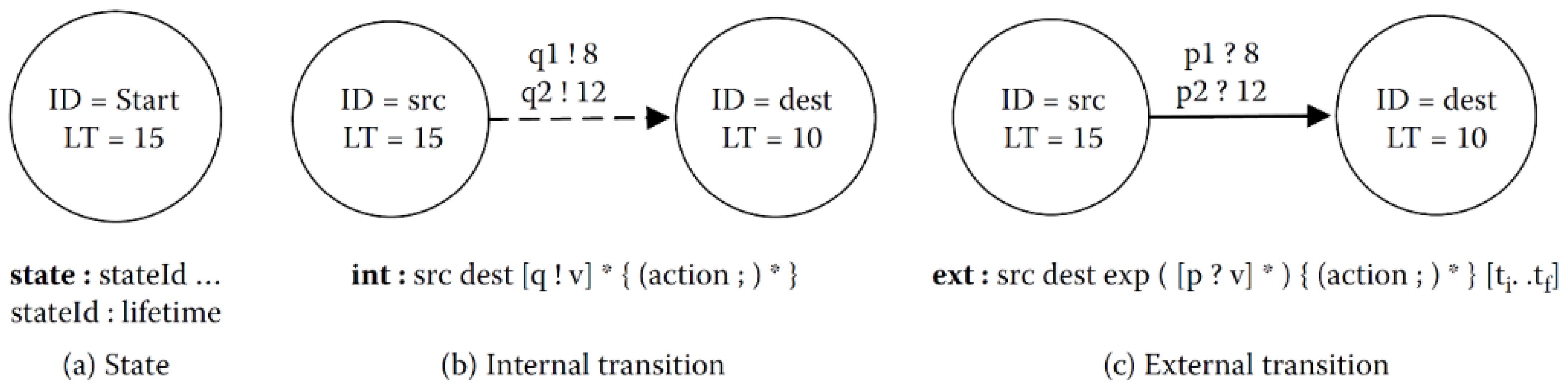
Figure 3.
DEVS coupled models using DEVS-Graphs [12].
Figure 3.
DEVS coupled models using DEVS-Graphs [12].
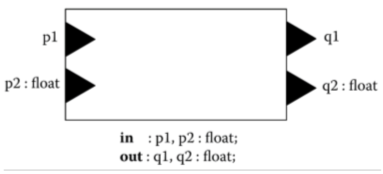
Figure 4.
Project Lifecycle for Each Identified Work Item.
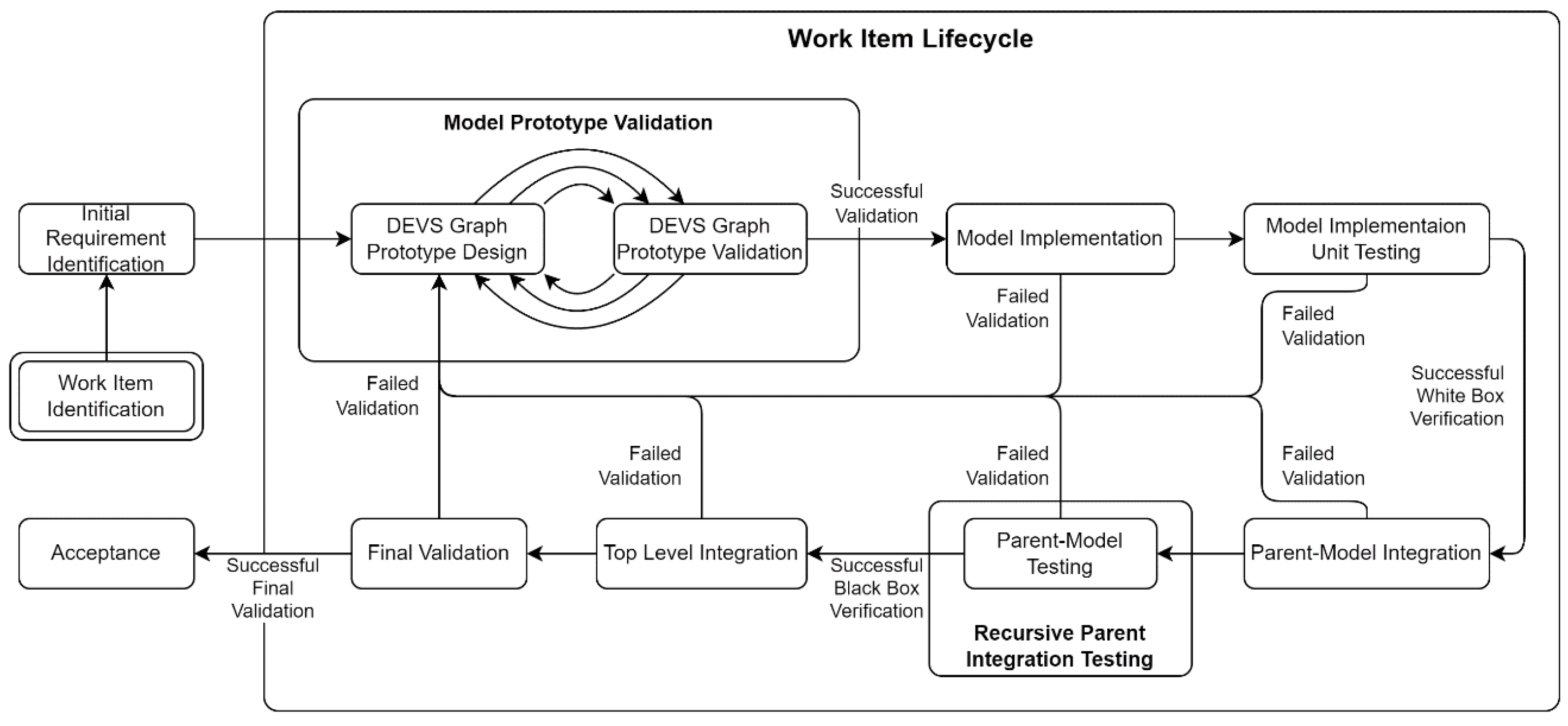
Figure 5.
Supervisor coupled model.
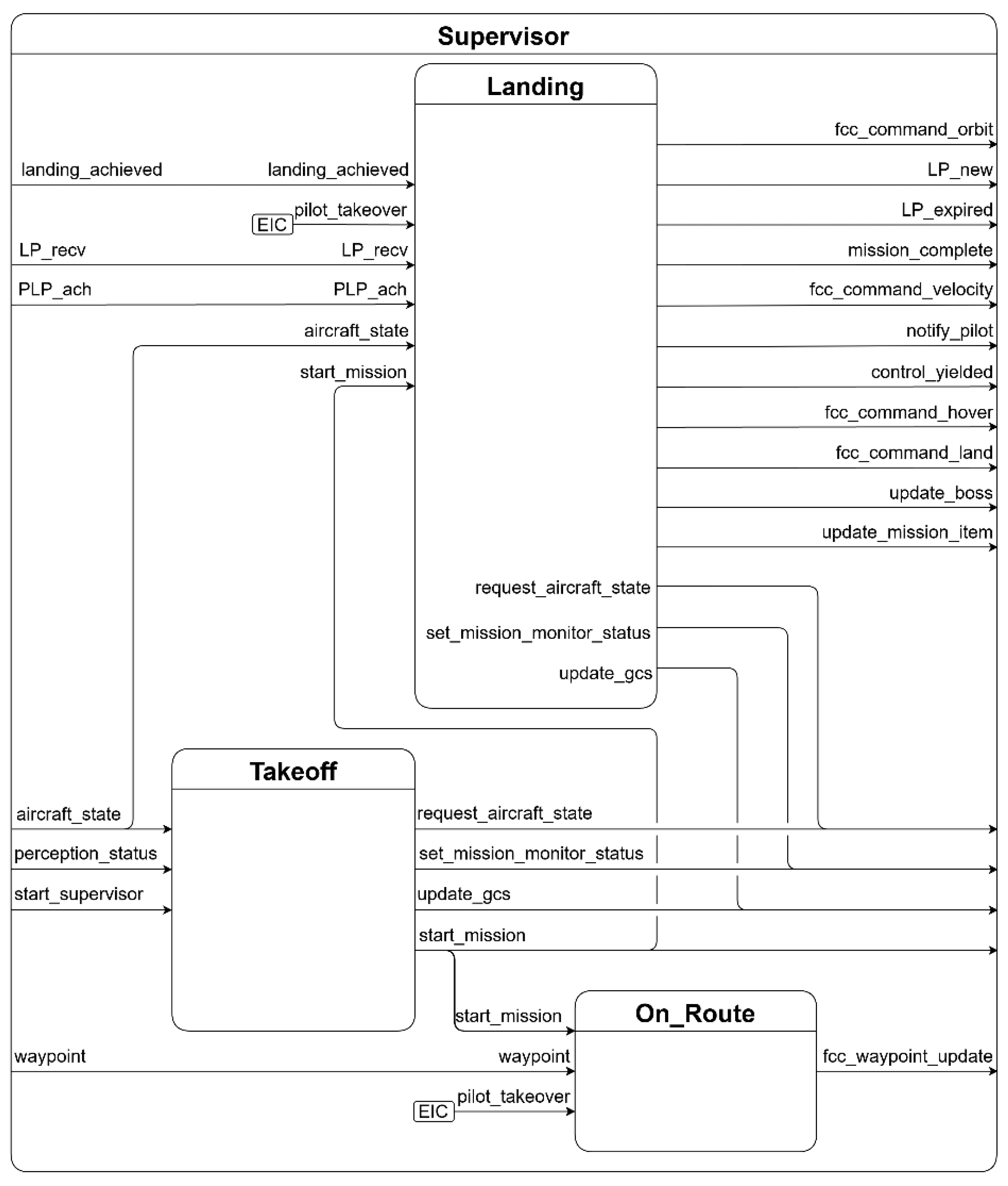
Figure 6.
Landing Point Manager atomic model.
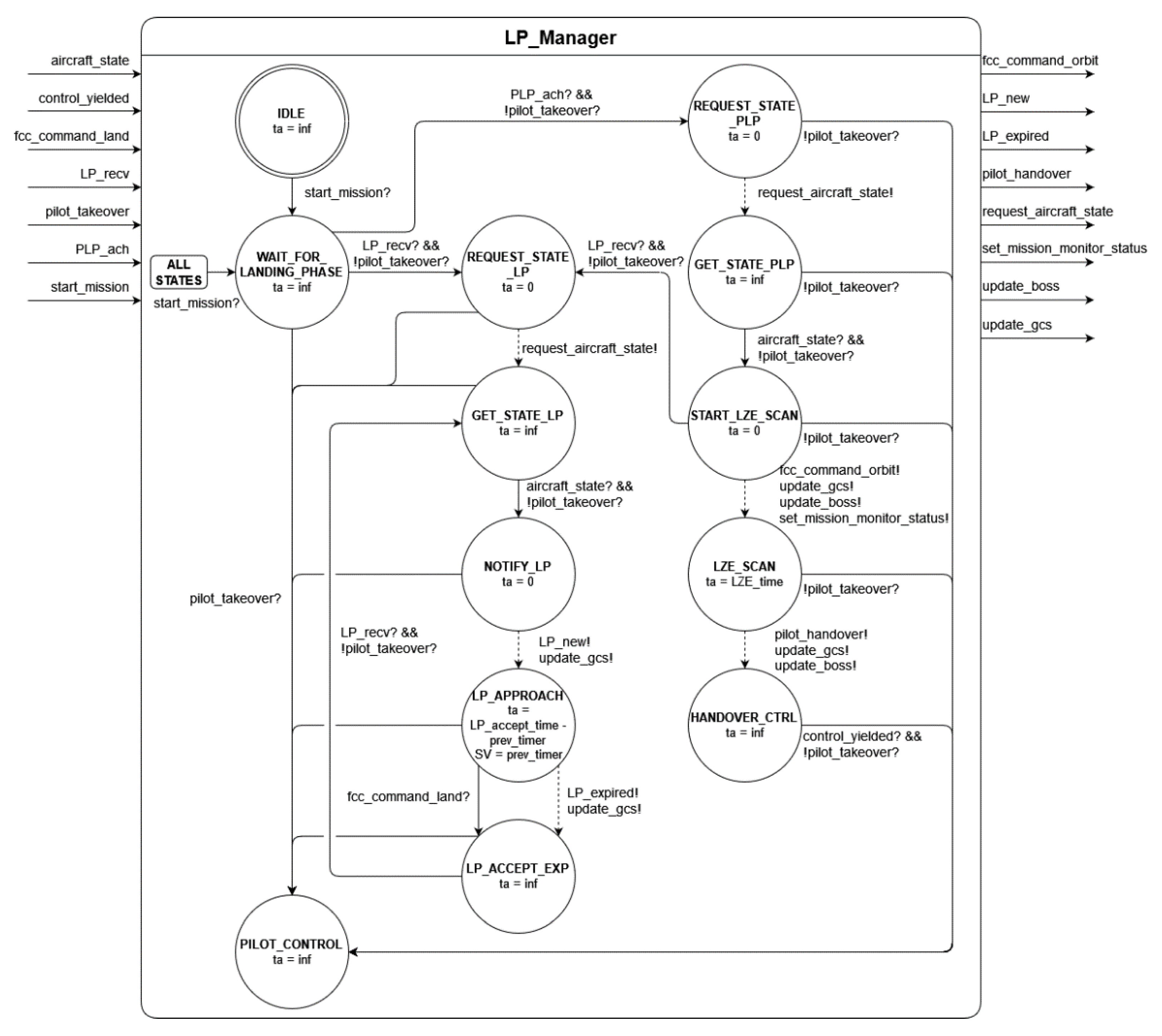
Figure 7.
Code snippet of the implementation of the Landing Point Manager atomic model.
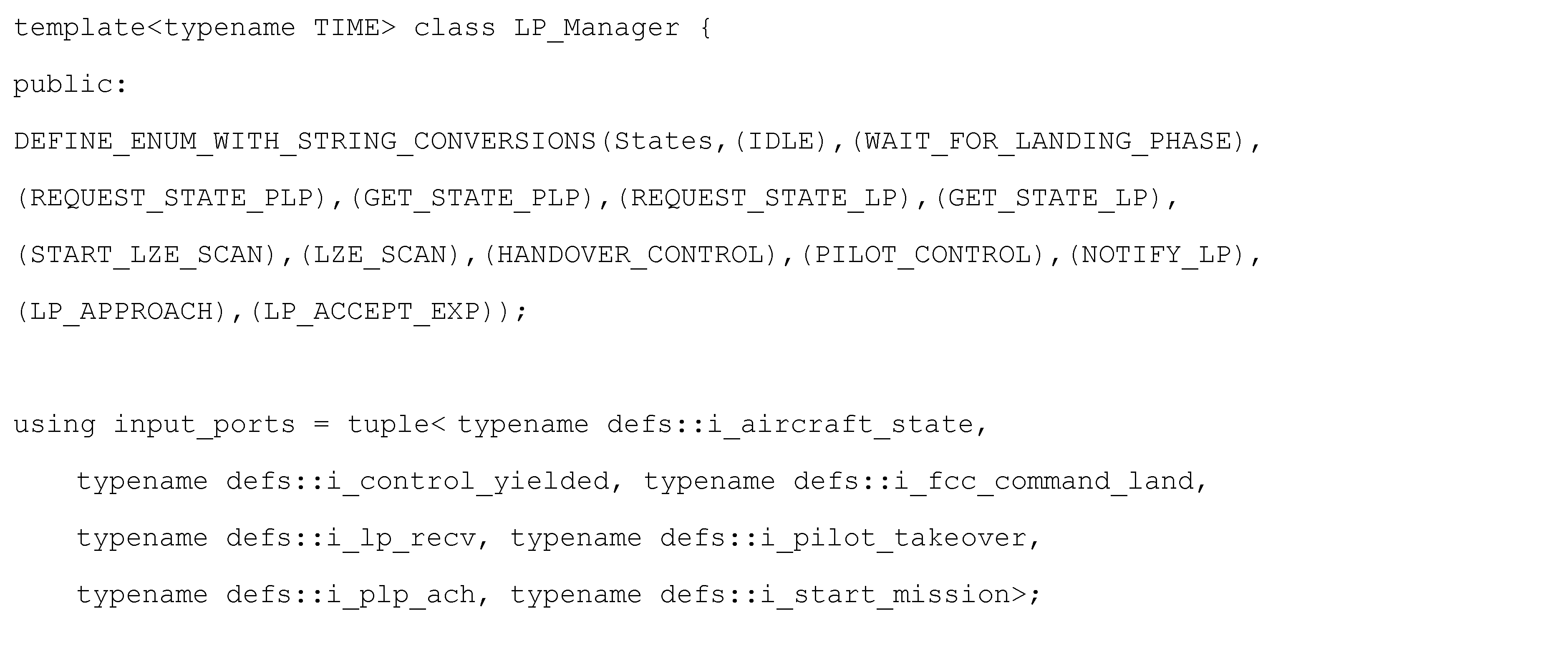
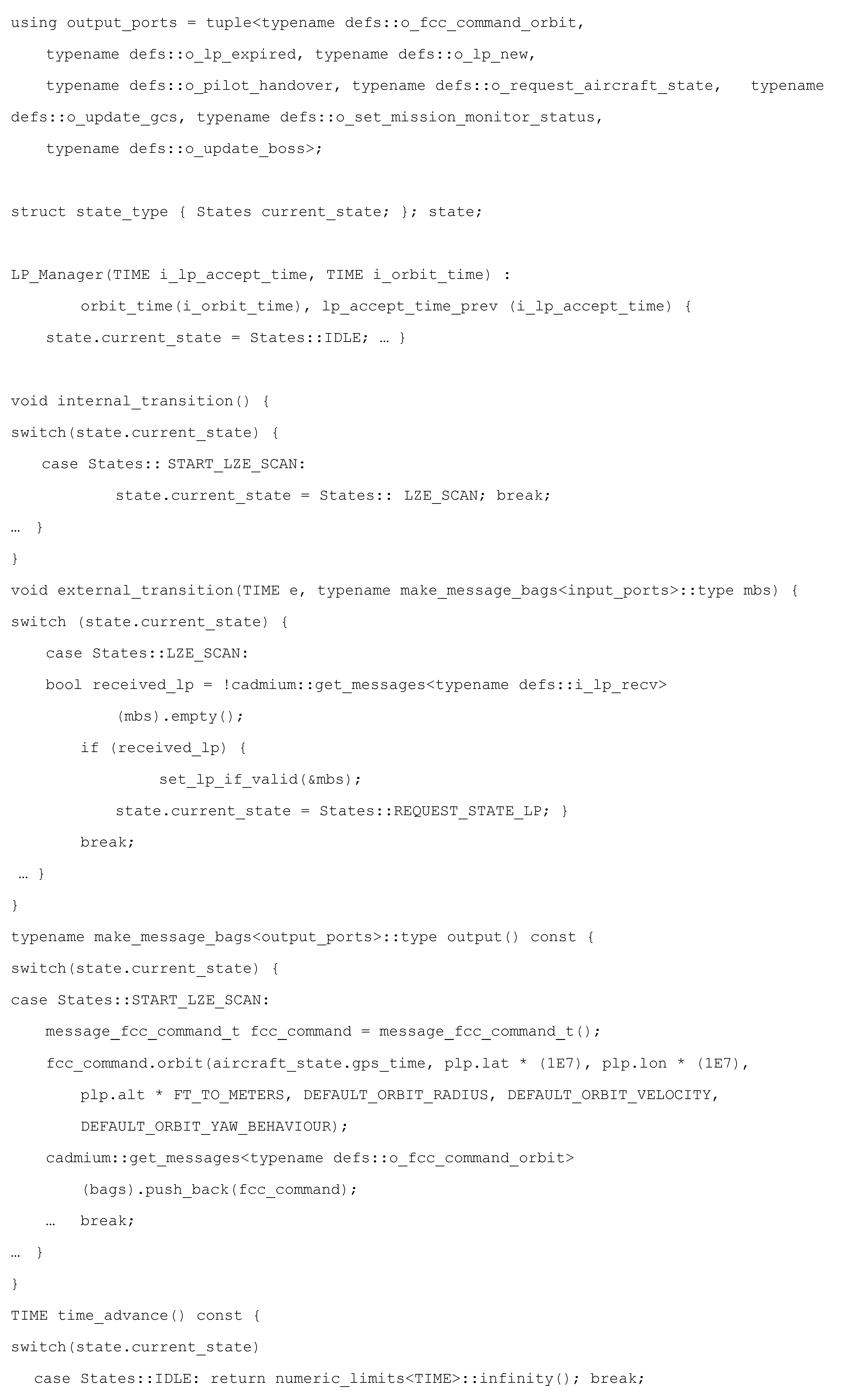

Figure 8.
Code snippet of the implementation of the Supervisor coupled model.
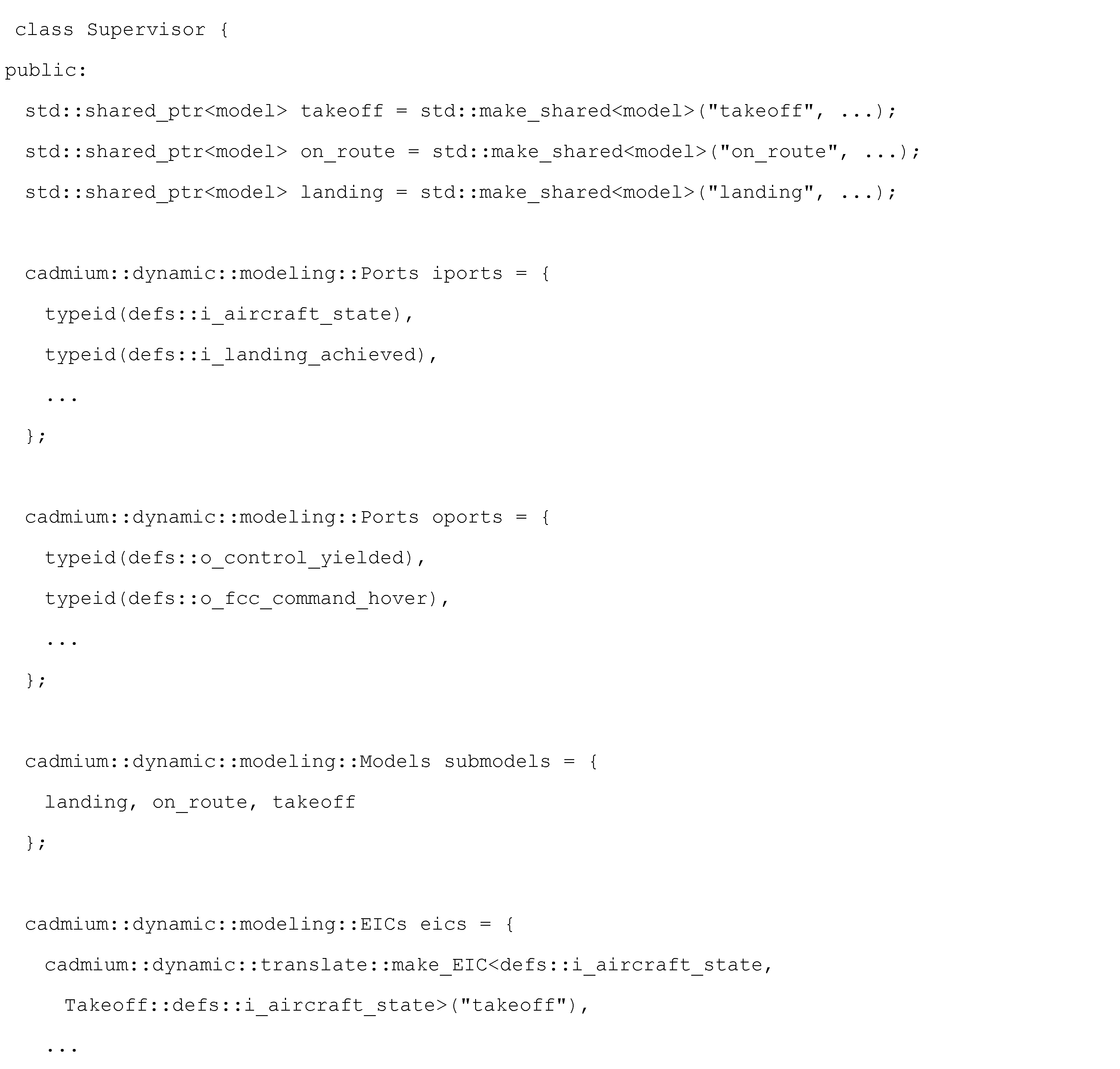
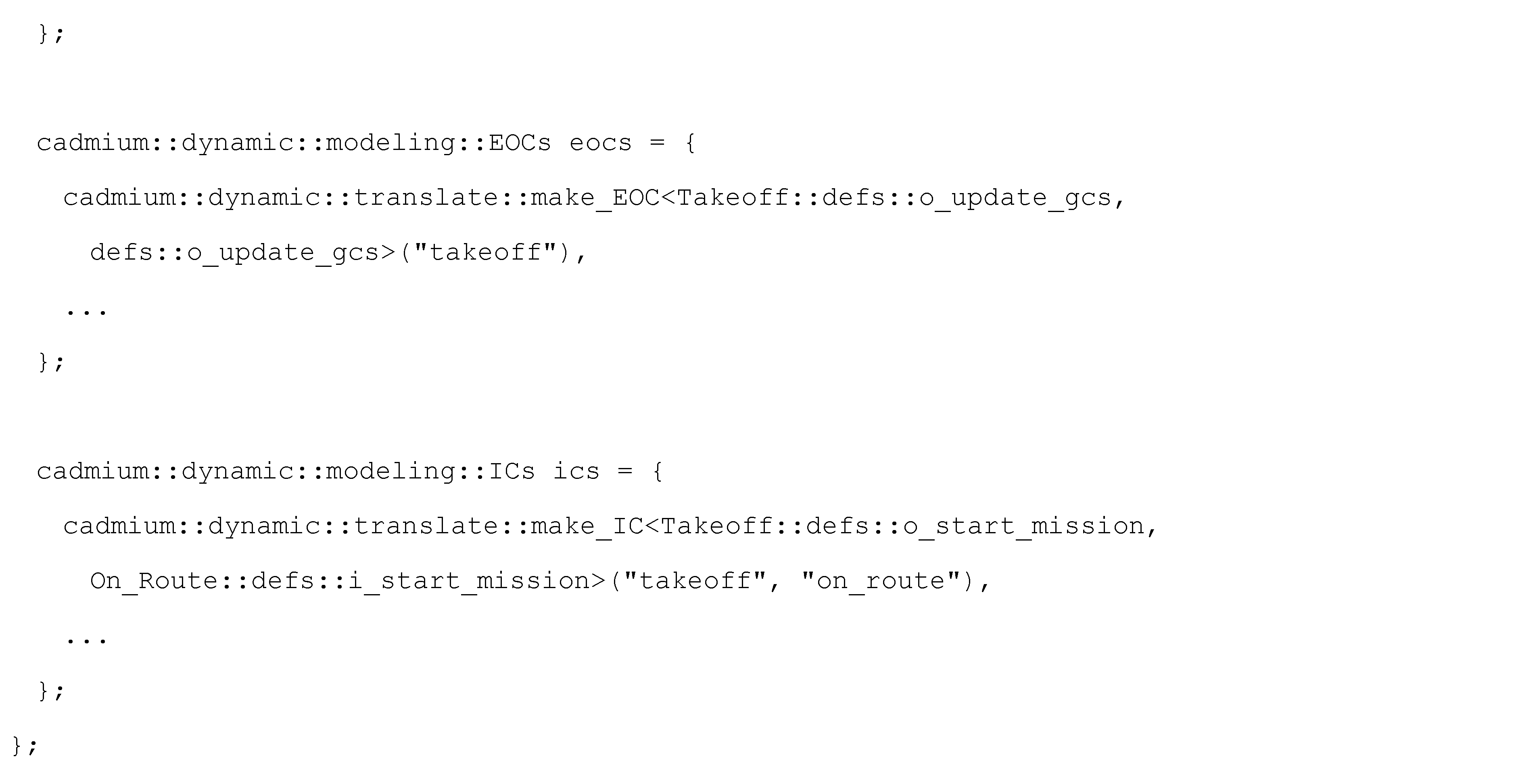
Figure 9.
UDP Output atomic model.
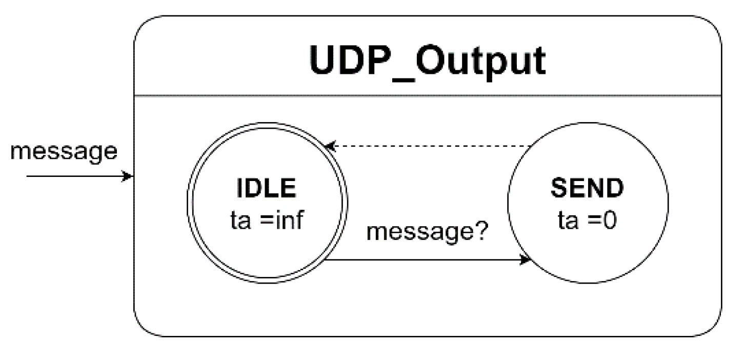
Figure 10.
Aircraft State Input atomic model.
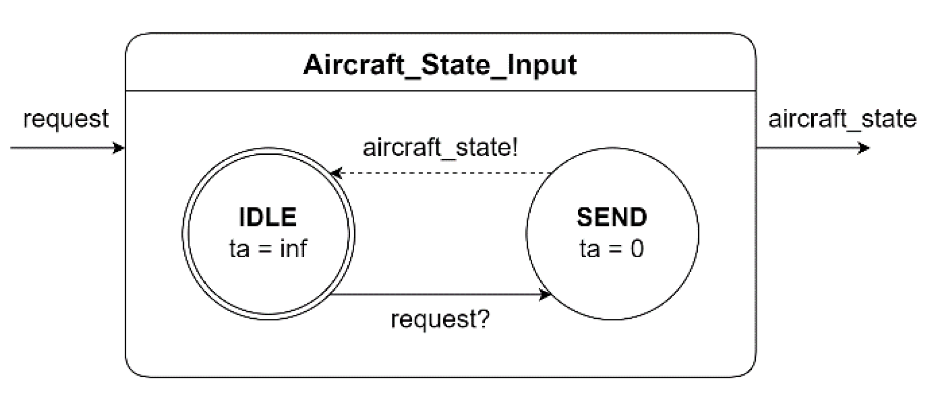
Figure 11.
Supervisor UDP Input atomic model.
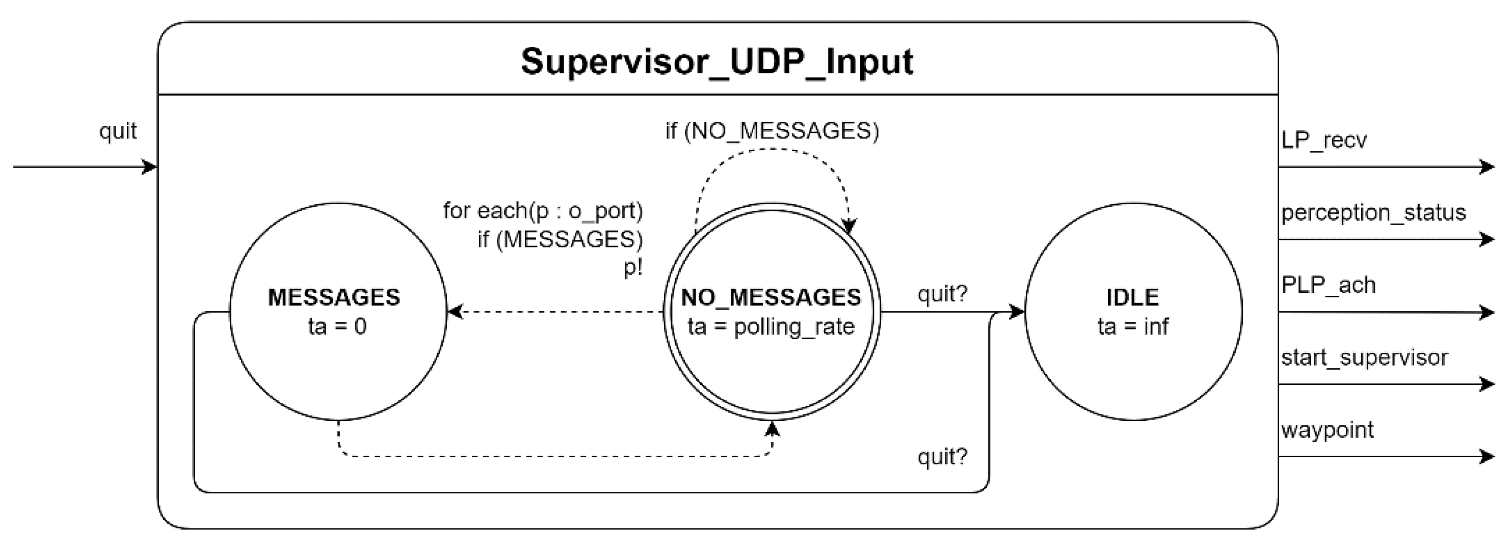
Figure 12.
Supervisor RUDP Output atomic model.
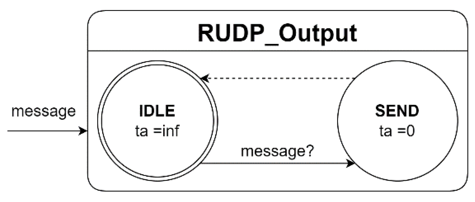
Figure 13.
Example of a Test Driver for the Landing Point Manager atomic model.
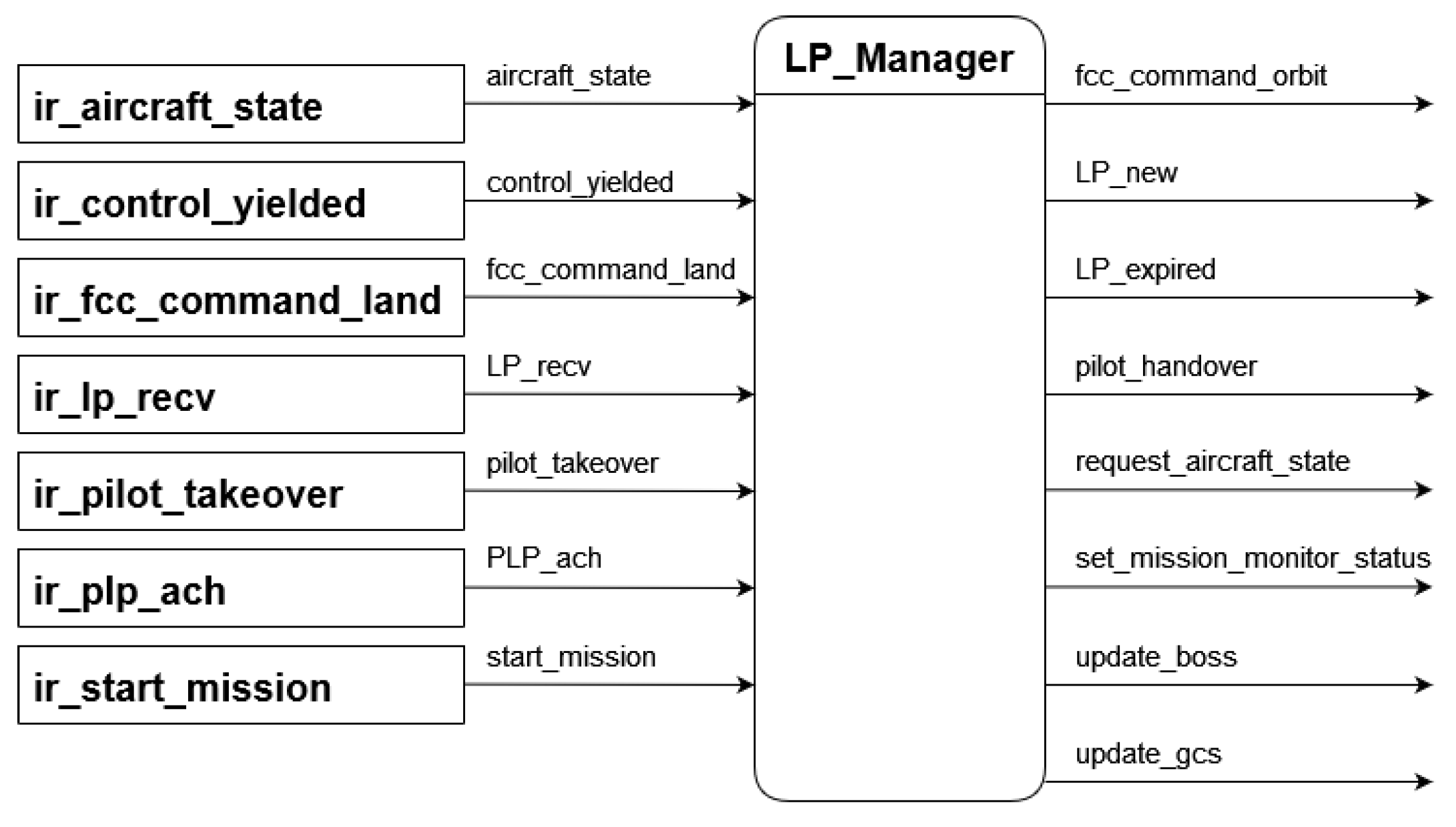
Figure 14.
Landing Point Manager transition tree.
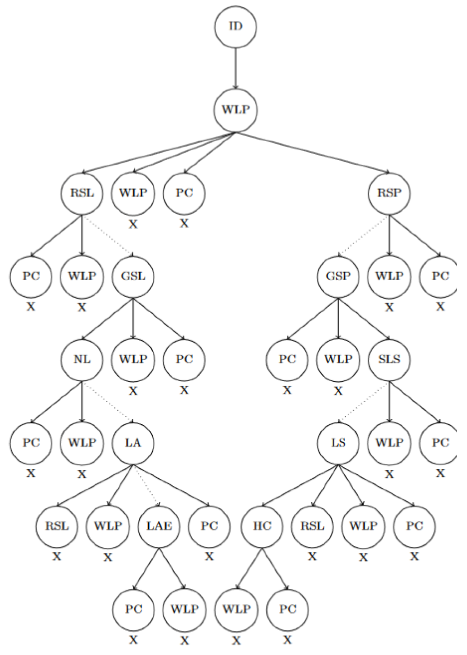
Figure 15.
Hardware and software architecture in the Bell 412 autonomy system.
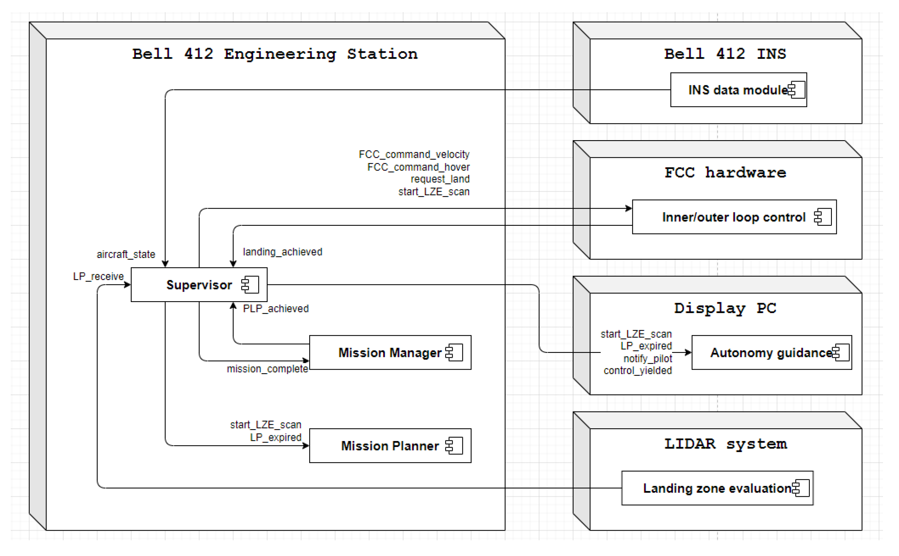

Table 1.
Inputs to the Supervisor coupled model.
| Input Port | Description of the inputs received |
| aircraft_state | Receives the current state of the aircraft |
| landing_achieved | Signal indicating that the aircraft has successfully landed |
| lp_recv | Receives the landing point from the perception system |
| perception_status | Operational status of the perception system |
| pilot_takeover | Signal indicating that the pilot has taken control |
| plp_ach | Signal indicating that the planned landing point has been achieved |
| start_supervisor | Signal indicating the mission has started and takeoff should commence |
| waypoint | Receives the next waypoint in the mission to handle |
Table 2.
Outputs from the Supervisor coupled model.
| Output port | Description of the outputs sent |
| control_yielded | Sends an acknowledgement that the supervisor has relinquished control of the aircraft |
| fcc_command_hover | Sends hover command to the FCC |
| fcc_command_land | Sends land command to the FCC |
| fcc_command_orbit | Sends orbit command to the FCC |
| fcc_command_velocity | Sends velocity command to the FCC |
| fcc_waypoint_update | Sends waypoint command to the FCC |
| lp_expired | Sends notification that the LP accept timer has expired |
| lp_new | Sends new valid landing point |
| mission_complete | Declares the mission as being complete after landing |
| notify_pilot | Notifies the pilot that they should take control of the aircraft |
| request_aircraft_state | Requests the current aircraft state |
| set_mission_monitor_status | Tells the Mission Manager to stop monitoring mission progress |
| start_mission | Sends a notification that the mission has started |
| update_boss | Sends updates to autonomy guidance |
| update_gcs | Sends updates to the mission planning software |
| update_mission_item | Updates Mission Manager that the last mission item has been reached |
Table 3.
Simulation test inputs to the Landing Point Manager atomic model.
| LP_Manager - Test: 0 | ||
| Time | Input Port | Value |
| 00:00:02:000 | start_mission | 1 |
| 00:00:10:000 | plp_ach | 0 10 45 -75 100 45 |
| 00:00:12:000 | aircraft_state | 99 0 0 0 0 0 0 |
| … | … | … |
Table 4.
Simulation results for the tests of the Landing Point Manager atomic model.
| LP_Manager | Test: 0 | ||
| Time | State | Output Port | Value |
| 00:00:00:000 | IDLE | ||
| 00:00:02:000 | WAIT_FOR_LANDING_PHASE | 1 | |
| 00:00:10:000 | REQUEST_STATE_PLP | 0 10 45 -75 100 45 | |
| 00:00:10:100 | GET_STATE_PLP | o_request_aircraft_state | 1 |
| … | … | … | … |
| Test: 1 | |||
| Time | State | Output Port | Value |
| 00:00:00:000 | START_LZE_SCAN | ||
| 00:00:00:001 | PILOT_CONTROL |
Disclaimer/Publisher’s Note: The statements, opinions and data contained in all publications are solely those of the individual author(s) and contributor(s) and not of MDPI and/or the editor(s). MDPI and/or the editor(s) disclaim responsibility for any injury to people or property resulting from any ideas, methods, instructions or products referred to in the content. |
© 2025 by the authors. Licensee MDPI, Basel, Switzerland. This article is an open access article distributed under the terms and conditions of the Creative Commons Attribution (CC BY) license (http://creativecommons.org/licenses/by/4.0/).
Copyright: This open access article is published under a Creative Commons CC BY 4.0 license, which permit the free download, distribution, and reuse, provided that the author and preprint are cited in any reuse.


