
Submitted:
16 December 2025
Posted:
18 December 2025
You are already at the latest version
Abstract
Ensuring the required microclimate parameters is the most critical task in hot climates. In pig farms, air cooling is provided by means of steam-compression chillers or water-evaporative cooling, which is the simplest way to cool the air. The implementation of water-evaporative cooling depends largely on the interaction of the media involved in this process. The paper considers the process of interaction of cooling water with the surface of a cellular polycarbonate heat exchanger. A mathematical model describing the process of wetting the sprayed surface of the heat exchanger is obtained. The dependence of theoretical water flow rate to provide air cooling in a given operation mode is determined. Production tests of recuperative heat recovery unit with heat exchanger made of cellular polycarbonate equipped with water evaporative cooling system were carried out. The efficiency of water-evaporative cooling of air has been determined, which was reflected in the temperature reduction by 6.3 °C. Characteristic operating modes of the unit, depending on the cooling water flow rate, providing effective air cooling are revealed.
Keywords:
water-evaporative cooling
; evaporation
; sprayed surface
; wetting ability
; heat recovery unit
; heat exchanger
1. Introduction
Resource and energy saving determine the vector of development of heating and ventilation technology. The problems of providing the required microclimate are most pronounced in extremely cold and hot conditions [1,2]. Taking into account the peculiarities of operating conditions and enormous air exchanges, typical solutions for industrial and domestic air conditioning systems do not meet the requirements [3,4].
Air cooling in pig farms can be provided by water-evaporative cooling systems and Vapor-compression refrigeration units (VCRU), which are rarely used in livestock farming (Figure 1.) [1,5,6]. Water evaporative cooling is fundamentally simpler, less demanding in terms of maintenance and operating conditions. However, its potential is significantly dependent on outdoor temperature and relative humidity and has a number of limitations. Water evaporative cooling can be implemented in various ways by means of different designs. It is worth highlighting water spraying systems with sprayed surfaces, which can be in panel and modular form (Figure 1).
Calculation of energy efficiency of the considered cooling systems for their comparative evaluation, carried out under the condition of completing the pig finishing house for 2300 heads in the Tambov region showed the greatest energy efficiency of sprayed panels (Figure 2). In the calculations performed, the potential cooling capacity of the VCRU was considered to be absolute.
Heat recovery systems are a promising trend in microclimate systems design. This is due to the constant rise in energy prices and the need to maintain high air exchange rates. The following distribution of heat losses is typical for livestock buildings: 2-5% of heat is lost through the walls and floor, 8-15% of heat losses are attributed to the roof and 80-90% of heat is removed with ventilation air [7,8] (Figure 3). Thus, utilization of heat removed with ventilation air will reduce the financial costs of heating the livestock room.
It is possible to utilize the heat of exhaust air by using heat exchangers of various designs, the classification of which is shown in Figure 4 [9,10].
Analysis of designs and energy performance of heat exchangers has shown that systems with intermediate coolant provide an opportunity for free spatial layout of supply and exhaust systems, while they are relatively resource demanding, complex, require additional maintenance, and heat pipes are of low capacity (Table 1). Regenerative heat exchangers do not provide flow separation, which causes dissolved ammonia, microflora and other pollutants in the condensate to enter the supply air. Regenerative heat exchangers are the most suitable for the required conditions.
Heat recovery and water evaporative cooling was implemented in the design of a combined air-conditioning unit, which in winter is used for heating the supply air, and in summer realizes the effect of water evaporative cooling.
2. Materials and Methods
The implementation of the physical potential of water evaporative cooling depends largely on the properties of the media involved in the process and the nature of their interaction. The process is multifactorial and depends primarily on the parameters of the cooled air (outdoor air temperature to and initial air moisture content di), which are determined by weather conditions and the required microclimate (tint, φint) [11]. The listed fundamental indicators determine the physical potential of water evaporative cooling, while the completeness of its realization depends on the characteristics of a particular unit and is the subject of optimization problem [12,13].
The efficiency of saturation of the treated air with moisture, as well as the degree of its cooling, depends on the area of contact between the media, aerodynamic characteristics, process duration and other characteristics. Of those metrics that we can effectively influence, the area of the interaction surface is the most significant. It is important to note that it is different from the sprayed surface area and is determined by the properties of the interacting media, flow rate, and spraying method [14,15,16].
The use of water-evaporative cooling is significantly cheaper than vapor-compression refrigeration units. Water is extracted at the facility, and the specific energy consumption per unit of cold produced is an order of magnitude lower. At the same time, water is a valuable resource and it is reasonable to identify the dependence that determines the minimum water flow rate that guarantees the realization of the physical potential of water evaporative cooling in a particular unit [17].
The above can be written down in mathematical form:
where to is the outside air temperature, °С; di, df is the initial and final air moisture content, g/kg of dry air; S is the area of the sprayed surface, m2; Re is the Reynolds criterion; is the process duration, s; is the edge angle of wetting of the heat exchanger surface, °; b, h are the dimensions of the tube cross-section, m; Qw is hourly water flow rate, m3/h; ПΣ, Пs.f. is the total length of the water-air interaction line in the cross-section at jet and film modes, m; C(Ca+2, Mg+2) is the concentration of hardness salts.
Let’s consider the process of water-evaporative cooling in a heat exchanger consisting of cellular polycarbonate plates with channels of square cross-section. A downward flow of a two-phase mixture (water and air) in a rectangular channel is assumed, with liquid flowing down the walls and the core of the section represented by a flow of cooled air and small liquid droplets. As assumptions, we take the air and water flow rate to be constant, with the water flow rate determined from the condition of sufficiency to saturate the cooled air to a given moisture content.
In steady flow, liquid droplets are deposited on the walls of the unit. The process of water-evaporative cooling involves evaporation of liquid over the surface of the film with decreasing thickness of the film itself, while on an infinitesimal section dy the thickness of the liquid layer can be assumed to be unchanged.
In the steady-state regime the droplet sizes are negligibly small and commensurate with the sizes of molecules, the vapor-gas medium can be considered quasi-homogeneous. The droplet velocities are commensurate with the gas flow velocity, hence a two-speed regime takes place. The flow velocity of the vapor-gas medium is higher than that of the liquid film, which leads to accelerated flow of the liquid phase and increases the drag for the vapor-gas phase. Vertical orientation of channels in space excludes the influence of gravity on the character of phase velocity distribution in the cross section, i.e., axisymmetric distribution is characteristic.
In considering the problem at hand, it is important to determine the volume ratio of the gas and liquid phases. In the cross-section the area of gas phase Sг is distinguished and related to the cross-sectional area of the channel Si (cross-sectional area of one tube), the obtained value is called the volume concentration of the gas medium:
where Sg is the cross-sectional area of the tube occupied by the gas phase, m2; Si is the cross-sectional area of the tube, m2.
The fraction of the channel cross-section occupied by the liquid phase can be determined from the Equation (1-γ).
It is known that at gas volume concentrations less than 0.6 - 0.8 the liquid phase can form overlapping regions, and depending on the ratio of velocities and volume concentrations a bubble or slug flow regime can be formed. Only the dispersed and dispersed-film regimes are considered here. The liquid films can be completely interlocked, forming a closed ring in cross-section, or form separate jets. The nature of the film formed is largely determined by the properties of the interacting substances, with wetting ability having the most significant influence.
When considering wetting ability, two limiting cases could be distinguished: absolute wetting ability and absolute non-wetting. In the first case the marginal wetting angle is 0° and the liquid spreads out in a thin film over the surface, in the second case the marginal wetting angle is 180° and the moisture collects in droplets. In most real cases there is an intermediate state (Figure 5).
The relationship between the surface energies of interacting bodies and the equilibrium boundary wetting angle is determined by Young’s law (16).
where σ is the surface energy at the interface; 1, 2, 3 are the liquid, gas and solid, respectively.
3. Results
Let us consider an example of film and jet fluid flow in the cross and longitudinal sections of the unit. The unit is a plurality of elementary tubes, let us consider the process using a single tube as an example [18].
In case of good wetting ability and sufficient water flow a continuous film is formed (Figure 6a), otherwise water collects in drops or runs down the surface in separate streams, in hydrodynamics of jets such phenomenon is called semi-limited jet (Figure 6b and Figure 7).
The volumetric gas concentration can also be expressed by the following equation:
where W, Qw are the air and water flow rates in the cooler, m3/h.
In the case under consideration, the water flow rate is four orders of magnitude less than the air flow rate, so its effect on the air capacity can be considered insignificant. Consequently, the statement about the constancy of the volumetric flow rate is true.
If the water evaporates completely, dissolved salts are deposited on the surface of the unit. Some form insoluble sludge that contaminates the unit and incurs operational costs for cleaning. Calcium and magnesium salts, so-called hardness salts, have these properties. Taking into account their concentration, water consumption for evaporation should be increased and at least 10% of the circulating water should be discharged to the sewer. Otherwise, the concentration of salts in the recirculate will increase.
Since the contact area of the media is directly proportional to the evaporation rate, the ratio of the surface areas of the jets facing the gas core at different wetting ability will reflect the effect of wetting ability on the efficiency of water-evaporative cooling (humidification of the supply air).
The length of the considered section Δl of the tube decreases at the ratio of areas and has no influence on the described ratio, only the perimeter matters. It is important to obtain a comparative value derived from the ratio of the contact line length at the current marginal wetting angle to the reference contact length.
Let’s call this characteristic the evaporation area conversion factor:
where SΘ, Sref are the area of contact of media respectively at current value of marginal wetting angle and reference, m2; ПΘ, Пref are the lengths of contact line at current marginal wetting angle and reference, m.
It is advisable to take an available well-wetted material as a reference. In water evaporative cooling units, heavy paper is used as the material of choice. The marginal wetting angle for it is 20-30°. 25° is taken as the baseline.
In the case of the film regime, the length of the contact line can be defined as the perimeter of the closed surface by the following equation:
where b, h are the dimensions of the tube cross section, m (Figure 7); δ it the thickness of the liquid film, m.
Water consumption for evaporation is constant and is determined from the condition of sufficiency for the process:
where ds,do are the moisture content of supply and outdoor air, respectively, g/kg dry air.
Air moisture content is determined using the following equation:
where φ is the relative air humidity, %; e is the base of the natural logarithm; t is the air temperature, °C [12].
Outdoor air parameters are taken from climatic data. The moisture content of the supply air should not be greater than the moisture content of the air in the animal housing, hence one of the limit states will be the equality of the moisture content of the supply and indoor air. Solving (7) and (8) together, we obtain the theoretical water flow rate to ensure the given conditions:
The resulting flow rate must be increased by at least 10% based on the recirculate drainage.
Let us determine the thickness of the liquid film:
After some mathematical transformations, a quadratic equation of the standard form is obtained:
where are the area and perimeter of the tube, respectively.
from which
Solving jointly 6 and 12 with respect to the perimeter of the film, we obtain:
In the jet mode, at the same water flow rate as in the annular mode, the films will cluster under the action of surface tension, tending to adopt an energetically favorable state.
Obviously, the filament band origin is a droplet. Upon reaching a critical size, the drop rolls downward, carried away by gravity and the flow of cross-current air. The process takes place at a constant cooling water flow rate, droplets are formed one after the other, resulting in a filament band.
Water enters the heat exchanger by spraying from nozzles, the droplets have different dispersity and direction of movement, the surface is wetted randomly, i.e., uniformly within each filament bond. Consequently, it is acceptable to assume that the bonds formed will be close in size.
Determination of the total length of the water-air interaction line in the cross-section at the jet regime can be carried out by the following equation:
where ri is the radius of the i-th jet, m; 2Θ is the arc opening angle, rad (Figure 8).
As can be seen from Figure 8, the edge wetting angle is equal to half of the arc opening angle. For the convenience of calculations we will convert the units of angles from radians to degrees by multiplying by π/180, and the equation will take the following form:
Using the average value of the jet cross-sectional radius, Equation (15) can be rewritten as follows:
where n is the number of jets; is the average jet radius in cross section, m.
If the sum of bases is not less than the perimeter of the tube, the jets will close and the flow regime will change to annular film flow. These conditions can be expressed by a dependency:
where Пi is the perimeter of the tube, m, is the length of the base of the elementary jet, m.
From the triangle ODC (Figure 8) we can see that the base “a” (AC) and the radius of the jet are related, hence
To find the radius of the elementary jet, we examine the moment of drop detachment as fundamental. At this point, the droplet is balanced by the action of gravity, the frontal pressure from the airflow on the droplet, and the force of surface tension (Figure 8b).
The geometric characteristics of the cross section of the filament bond are assumed to be equal to the parameters of the drop at the moment of detachment. The drop can be represented as a segment of a sphere with radius “r” and base width “a”.
The balance of forces can be expressed by the following formula:
where S is the frontal area of the drop, m2; is the surface tension force, N; σ is the surface tension of water σ = 0.072 N/m).
The force of gravity is defined as the product of the mass of the liquid by the acceleration of free fall g, and the mass is expressed through the product of the volume by the density:
where ρw is the density of water, kg/m3, is the drop volume, m3.
The volume and frontal area of the droplet are calculated using the following equations:
It follows from Figure 8c that OD/r = cosΘ, at that OD = r - h, as a result of mathematical transformations we obtain:
Solving jointly Equations (21) and (23) we obtain:
Substituting Equations (20)-(23) into Equation (19) we obtain:
The solution of Equation (25) will be as follows:
Solving jointly Equations (2) and (22) we can find the number of jets and express the jet regime condition:
Solving together with Equation (5), we determine the conversion coefficient of evaporation area:
Thus, the minimum water flow rate for evaporation can be determined by the formula:
Or, taking into account Equation (9):
where Qw.min is the theoretical water flow rate to ensure cooling in a given mode, kg/h; = 1,1 is the drain coefficient, is the coefficient of evaporation area conversion.
Figure 9 shows the dependence of the relative evaporation area coefficient on the edge angle.
The range of adequate use of the model is in the range of = 20 … 120°. The droplet behavior cannot be described with the assumptions of the model outside of this range of wetting angle values.
At wetting angles above 80°, the coefficient values stabilize and reach 0.36.
The experimentally obtained marginal wetting angle of polycarbonate with water is 63° (Figure 10).
For surfaces with a marginal wetting angle of 60-65°, water consumption for evaporation should be increased by 2.3-2.4 times compared to the minimum necessary.
Let us construct a theoretical graph of the dependence of the jet base length on the wetting edge angle and the air flow velocity in the tube (Figure 11).
According to the obtained model, it can be concluded that in the considered velocity range its influence on the jet base area is insignificant.
4. Discussion
Production tests of the system of recuperative heat recovery unit with water-evaporative cooling system on the basis of irrigated panels were carried out in the pig finishing sector on the farm of “Firma Mortadel” LLC during the fattening period. The heat recovery unit was integrated into the pig house climate control system. The microclimate maintenance system was designed by the Canadian company “FGCLIMITED” using the equipment of the company “Ag-Coproductslimited”. Regulation of microclimate parameters was provided by the automation system according to the temperature and relative humidity sensor. During the control period, the outdoor air temperature ranged from -8 to +31 °C [8]. The efficiency of supply air cooling was monitored on the hottest days of the experimental period. During the tests the ambient air temperature was 30.4 °C, relative humidity 31.2%. The results of the tests are summarized in Table 2.
To identify the effectiveness of air cooling, the air temperature reduction as a function of cooling water flow rate was determined. The data obtained are summarized in Table 3.
On the basis of the data given in Table 3, a graph showing the decrease in supply air temperature from the water consumption used for panel irrigation is plotted (Figure 12).
The graph highlights the zones that characterize the operating modes of the unit, in the first zone there is a rapid decrease in the cooling temperature due to the deficit of moisture necessary for the implementation of the process. In the third zone, there is the detachment of dripping moisture and the spreading of spray with the air jet. The second zone provides effective cooling and is not accompanied by significant splashing.
5. Conclusions
The conducted research resulted in a relationship for determining the minimum water flow rate for cooling. The influence of the contact angle on the relative evaporation area coefficient was established, varying from 1.0 to 0.36 at contact angles from 20 to 120°. Experimental studies revealed that for polycarbonate surfaces, the minimum water flow rate required for evaporation should be increased by a factor of 2.3 to 2.4. Production tests of a system with a water-based evaporative cooling system based on sprayed panels showed a 6.3 °C reduction in supply air temperature.
Author Contributions
Software, D.S.; Validation, S.K.; Data curation, N.S. (Nikita Serov); Writing – original draft, I.I.; Writing – review & editing, N.S. (Nikolay Shevkun); Project administration, I.I.
Funding
This research received no external funding.
Conflicts of Interest
The authors declare no conflict of interest.
References
- Kanaan, M.; Amine, S.; Hmadi, M. Optimized Solar-Powered Evaporative-Cooled UFAD System for Sustainable Thermal Comfort: A Case Study in Riyadh, KSA. Thermo 2025, 5, 26. [Google Scholar] [CrossRef]
- Yang, P.; Yu, M.; Ma, X.; Deng, D. Carbon Footprint of the Pork Product Chain and Recent Advancements in Mitigation Strategies. Foods 2023, 12, 4203. [Google Scholar] [CrossRef] [PubMed]
- Xie, Y.; Min, K.; Ma, H.; Ding, R.; Wang, S.; Liu, Y. Performance and economic comparison of three annual air-conditioning systems in sow houses. Applied Thermal Engineering 2024, 239, 122114. [Google Scholar] [CrossRef]
- Shatalov, M. Obosnovanie parametrov teploutilizacionnoj ustanovki na baze polimernogo perekrestnotochnogo plastinchatogo teploobmennika dlya zhivotnovodcheskih pomeshchenij. dis. k-ta tekhn. nauk. 2010, 168, (in Russ.). [Google Scholar]
- Ahn, B.; Schmetzer, M.; Ro, P.I. Experimental Study of Aqueous Foam Use for Heat Transfer Enhancement in Liquid Piston Gas Compression at Various Initial Pressure Levels. Thermo 2025, 5, 39. [Google Scholar] [CrossRef]
- Ahn, B.; Schmetzer, M.; Ro, P.I. Experimental Study of Aqueous Foam Use for Heat Transfer Enhancement in Liquid Piston Gas Compression at Various Initial Pressure Levels. Thermo 2025, 5, 39. [Google Scholar] [CrossRef]
- Mastrucci, A.; Ruijven, B.; Byers, E.; Poblete-Cazenave, M.; Pachauri, S. Global Scenarios of Residential Heating and Cooling Energy Demand and CO2 Emissions. Clim. Change 2021, 168, 14. [Google Scholar] [CrossRef]
- Ignatkin, I.Y.; Kazantsev, S.P.; Shevkun, N.A.; Skorokhodov, D.M.; Serov, N.V.; Alipichev, A.Y.; Panchenko, V.A. Developing and testing the air cooling system of a combined climate control unit used in pig farming. Agriculture 2023, 13(2), 334. [Google Scholar] [CrossRef]
- Mishurov, N.P.; Kuz’mina, T.N. Energosberegayushchee oborudovanie dlya obespecheniya mikroklimata v zhivotnovodcheskih pomeshcheniyah: Nauchnyj analiticheskij obzor. In Rosinformagrotekh; (in Russ.); Moscow, 2004. [Google Scholar]
- Chernoivanov, V.I.; Fedorenko, V.F. Novye tekhnologii i oborudovanie dlya tekhnicheskogo perevooruzheniya i stroitel’stva svinovodcheskih ferm i kompleksov. In Rosinformagrotekh; (in Russ.); Moscow, 2006. [Google Scholar]
- Ignatkin, I.Y.; Shevkun, N.A.; Kononenko, A.S.; Ryabchikova, V.; Panchenko, V. Far North: Optimizing Heating Costs Lecture Notes in Networks and Systems. Intelligent Computing and Optimization 2023, 853, 43–50. [Google Scholar] [CrossRef]
- Kirsanov, V.V.; Ignatkin, I.Y. Matematicheskaya model’ vodoisparitel’nogo ohlazhdeniya v sistemah ventilyacii. Vestnik Federal’nogo gosudarstvennogo obrazovatel’nogo uchrezhdeniya vysshego professional’nogo obrazovaniya «Moskovskij gosudarstvennyj agroinzhenernyj universitet imeni V.P. Goryachkina in Russ.. 2017, 1, 14–20. [Google Scholar]
- Kapilan, N.; Isloor, A.M.; Karinka, S. A Comprehensive Review on Evaporative Cooling Systems. Results Eng. 2023, 18, 101059. [Google Scholar] [CrossRef]
- Yang, H.; Shi, W.; Chen, Y.; Min, Y. Research Development of Indirect Evaporative Cooling Technology: An Updated Review. Renew. Sustain. Energy Rev. 2021, 145, 111082. [Google Scholar] [CrossRef]
- Tripathi, R.J.; Kumar, D. A Holistic Approach for Solar-Driven HVAC Evaporative Cooling System: Comparative Study of Dry and Wet Channel. J. Build. Eng. 2024, 83, 108465. [Google Scholar] [CrossRef]
- A/L Sambathan, S.; Ismail, F.B.; Nasif, M.S. Underfloor Air Distribution Technology: A Review. AIP Conf. Proc. 2018, 2035, 070004. [Google Scholar] [CrossRef]
- Jaber, S.; Ezzat, A.W. Investigation of Energy Recovery with Exhaust Air Evaporative Cooling in Ventilation System. Energy Build. 2017, 139, 439–448. [Google Scholar] [CrossRef]
- ASHRAE. ASHRAE Handbook—HVAC Systems and Equipment. In Air-to-Air Energy Recovery Equipment; ASHRAE: Peachtree Corners, GA, USA, 2020; p. 26. [Google Scholar]
Figure 1.
Classification of cooling systems.
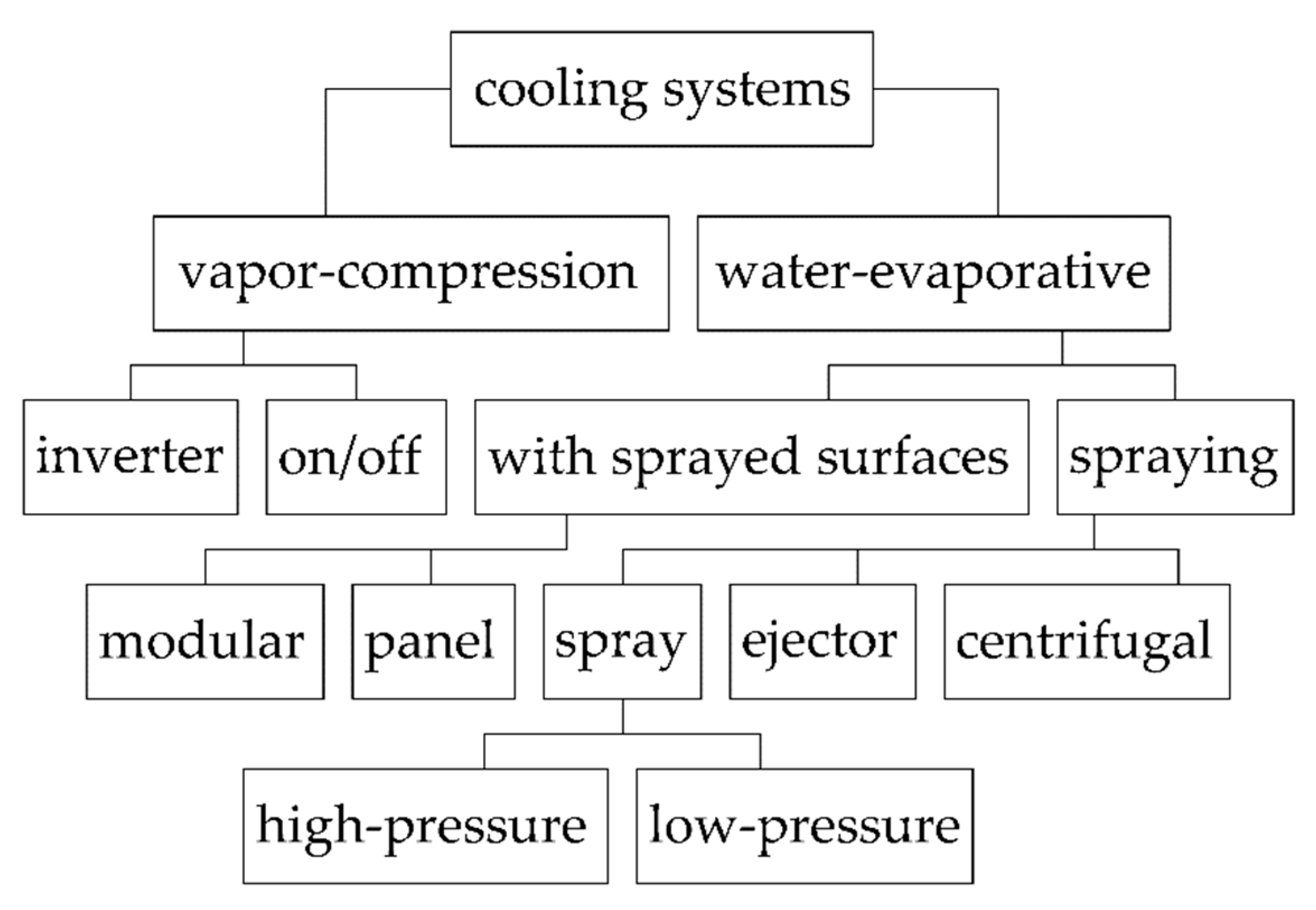
Figure 2.
Electric power consumption for the production of 1 kW of cold air, kW/kW.
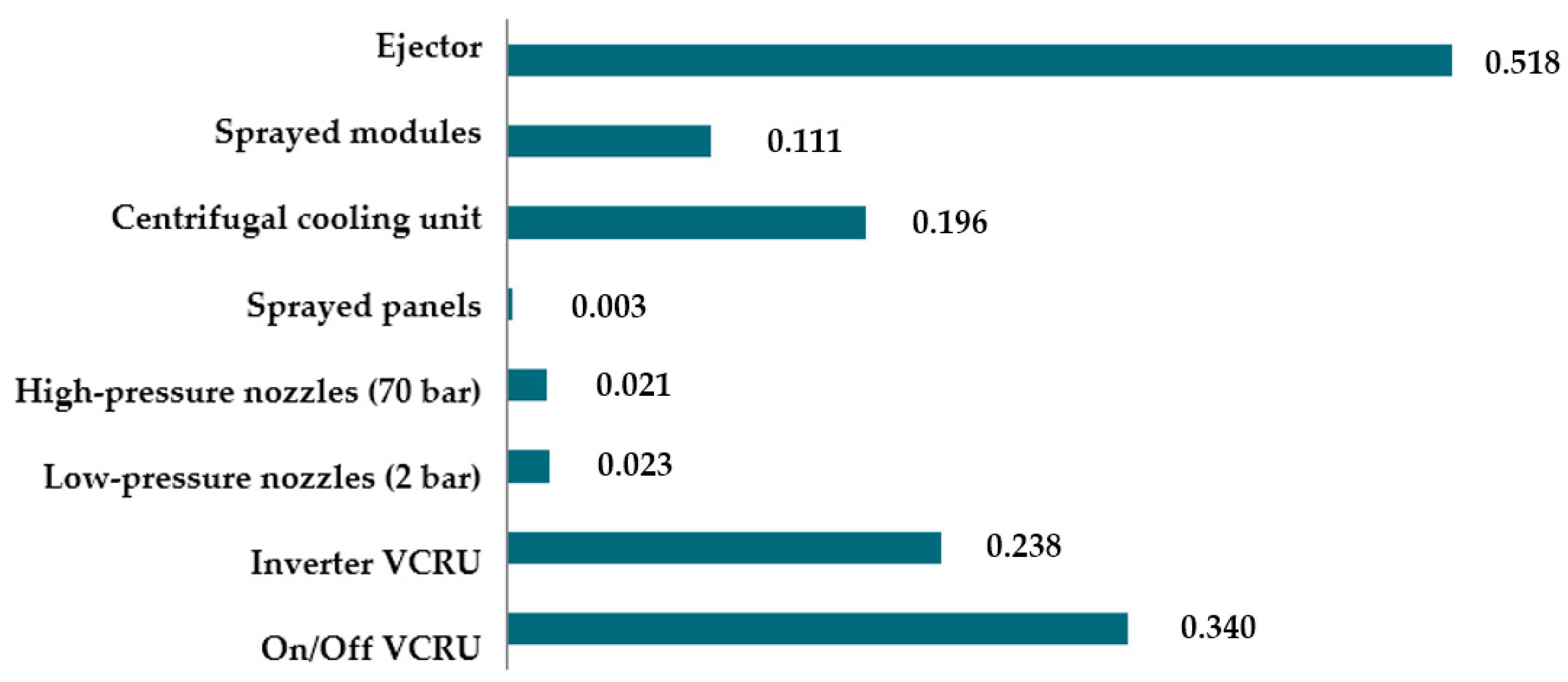
Figure 3.
Structure of heat losses in a modern pig house.
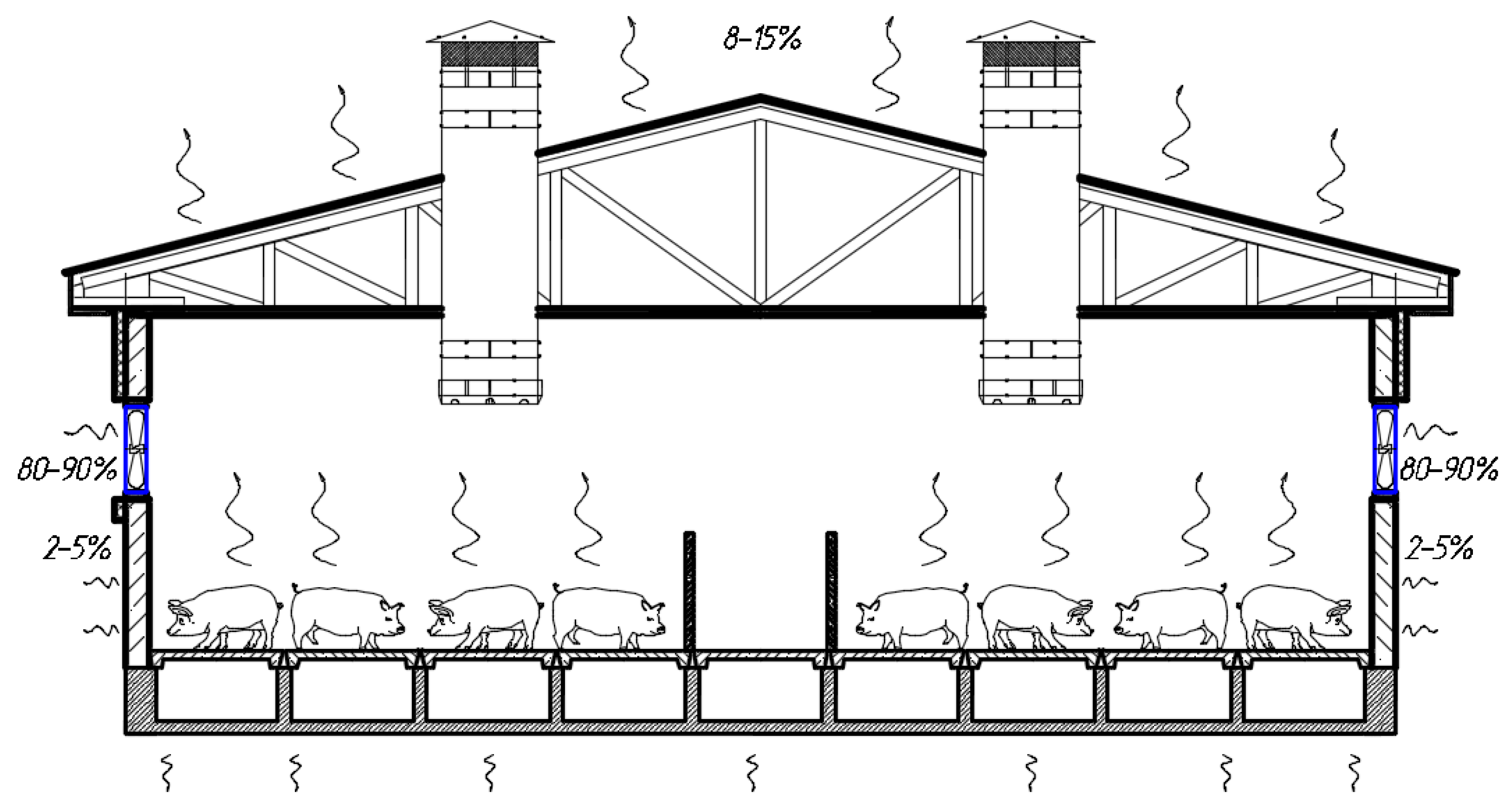
Figure 4.
Classification of heat exchangers.
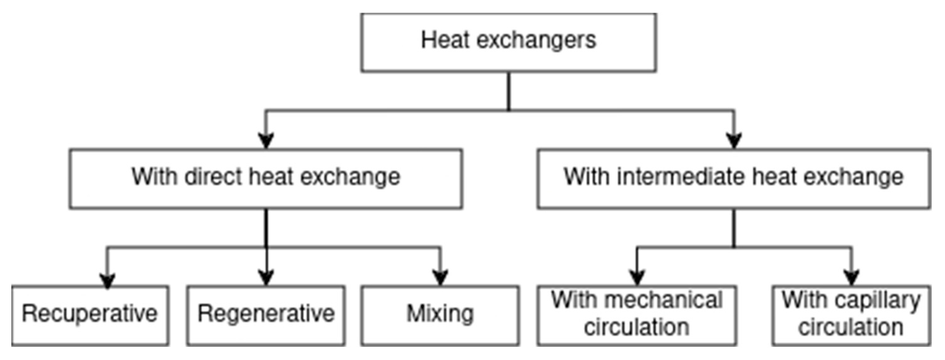
Figure 5.
Liquid wetting ability of a surface: a, b are respectively wetted and non-wetted by liquid surface.
Figure 5.
Liquid wetting ability of a surface: a, b are respectively wetted and non-wetted by liquid surface.
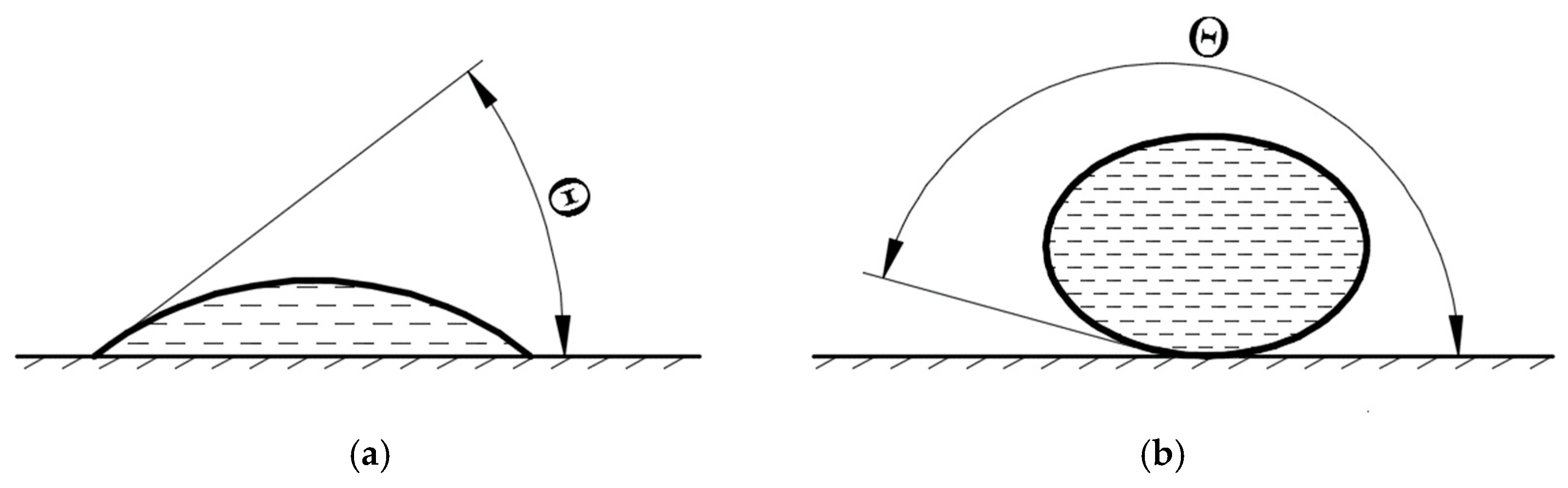
Figure 6.
Cross section of the heat exchanger tube: a - at film regime of fluid flow; b - at jet regime of flow.
Figure 6.
Cross section of the heat exchanger tube: a - at film regime of fluid flow; b - at jet regime of flow.
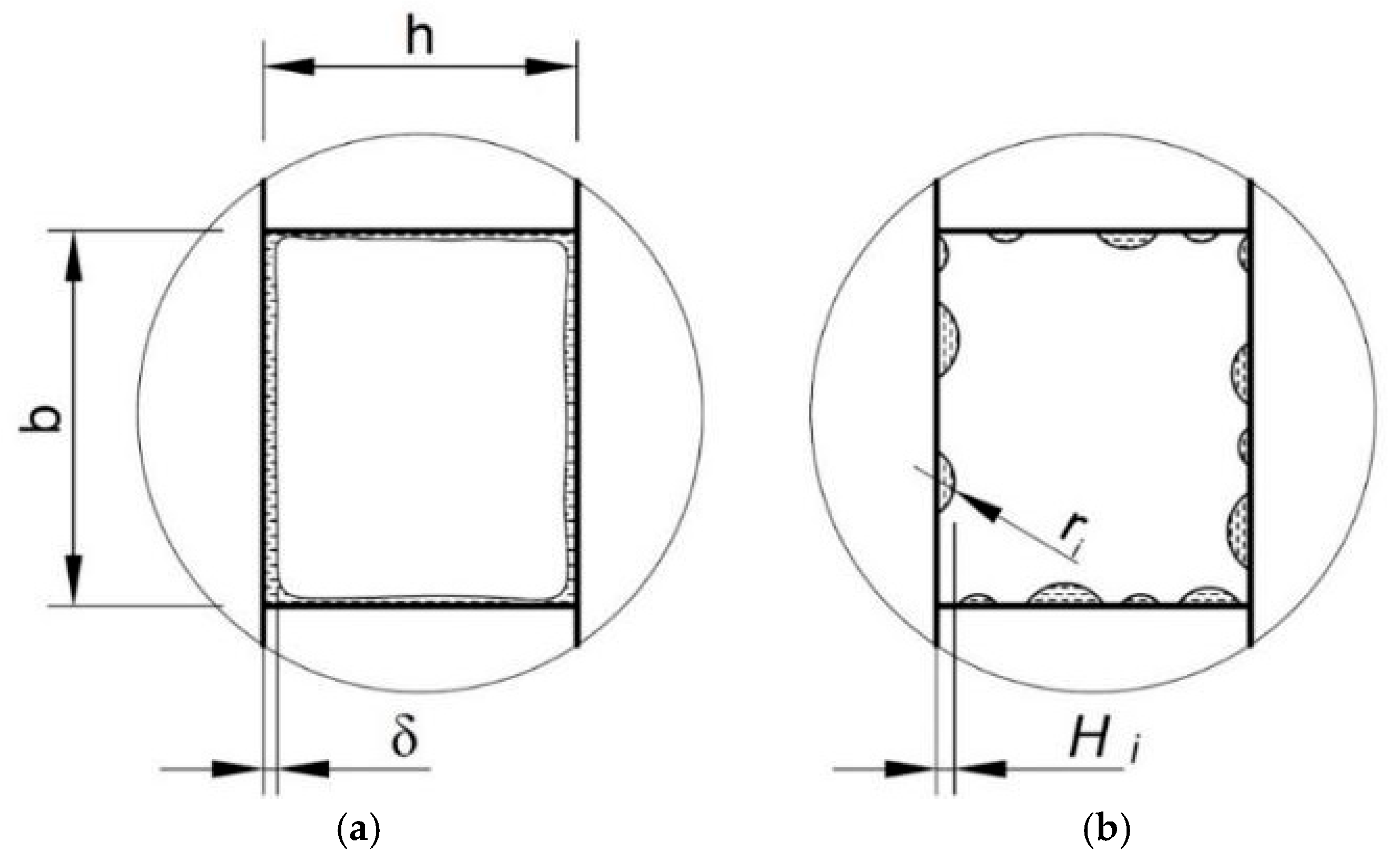
Figure 7.
Longitudinal cross-section of the heat exchanger tube in jet regime.
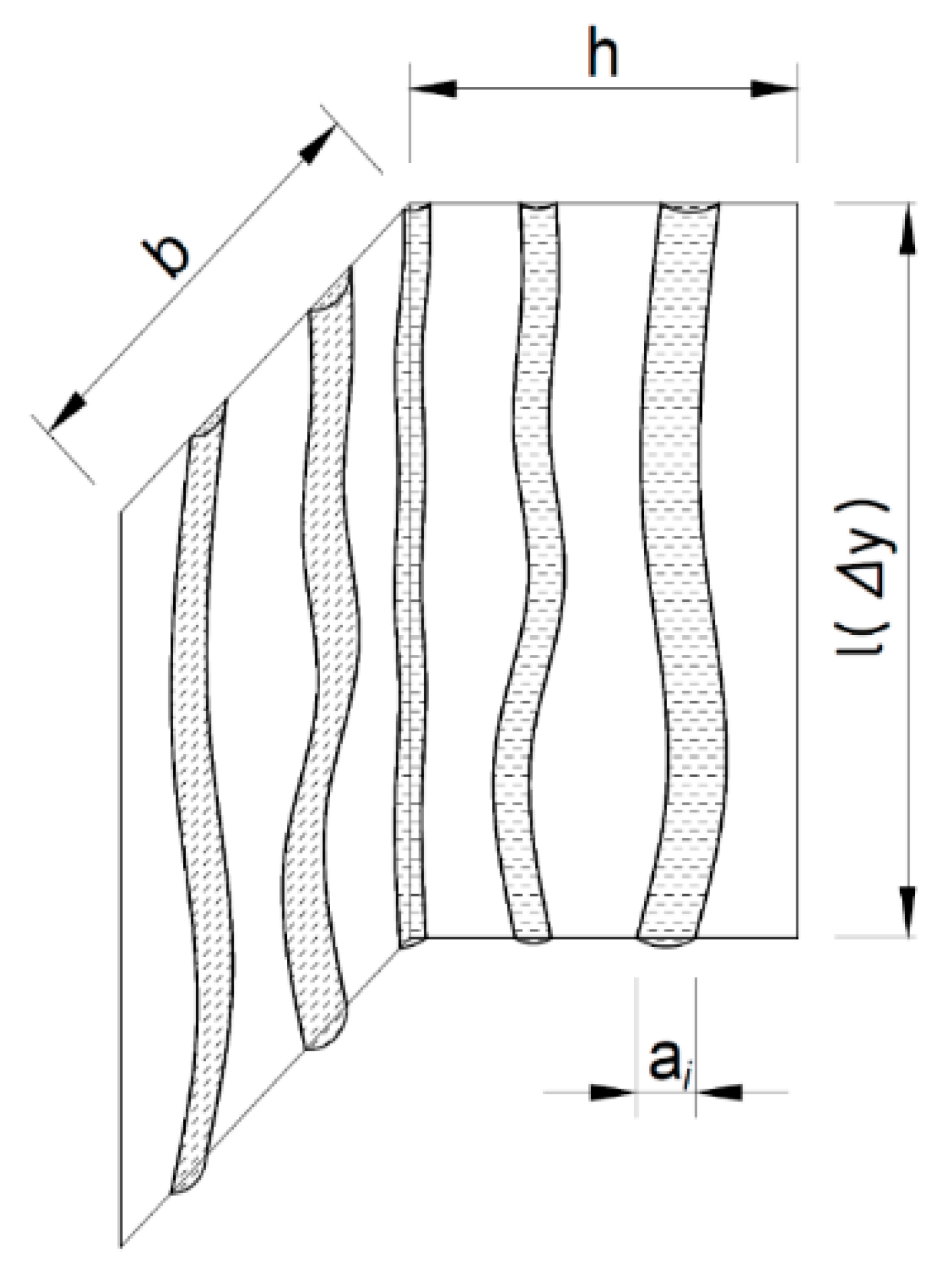
Figure 8.
Scheme for the calculation of geometric parameters of the jet cross-section: a - frontal view; b - side view; c - section A-A.
Figure 8.
Scheme for the calculation of geometric parameters of the jet cross-section: a - frontal view; b - side view; c - section A-A.
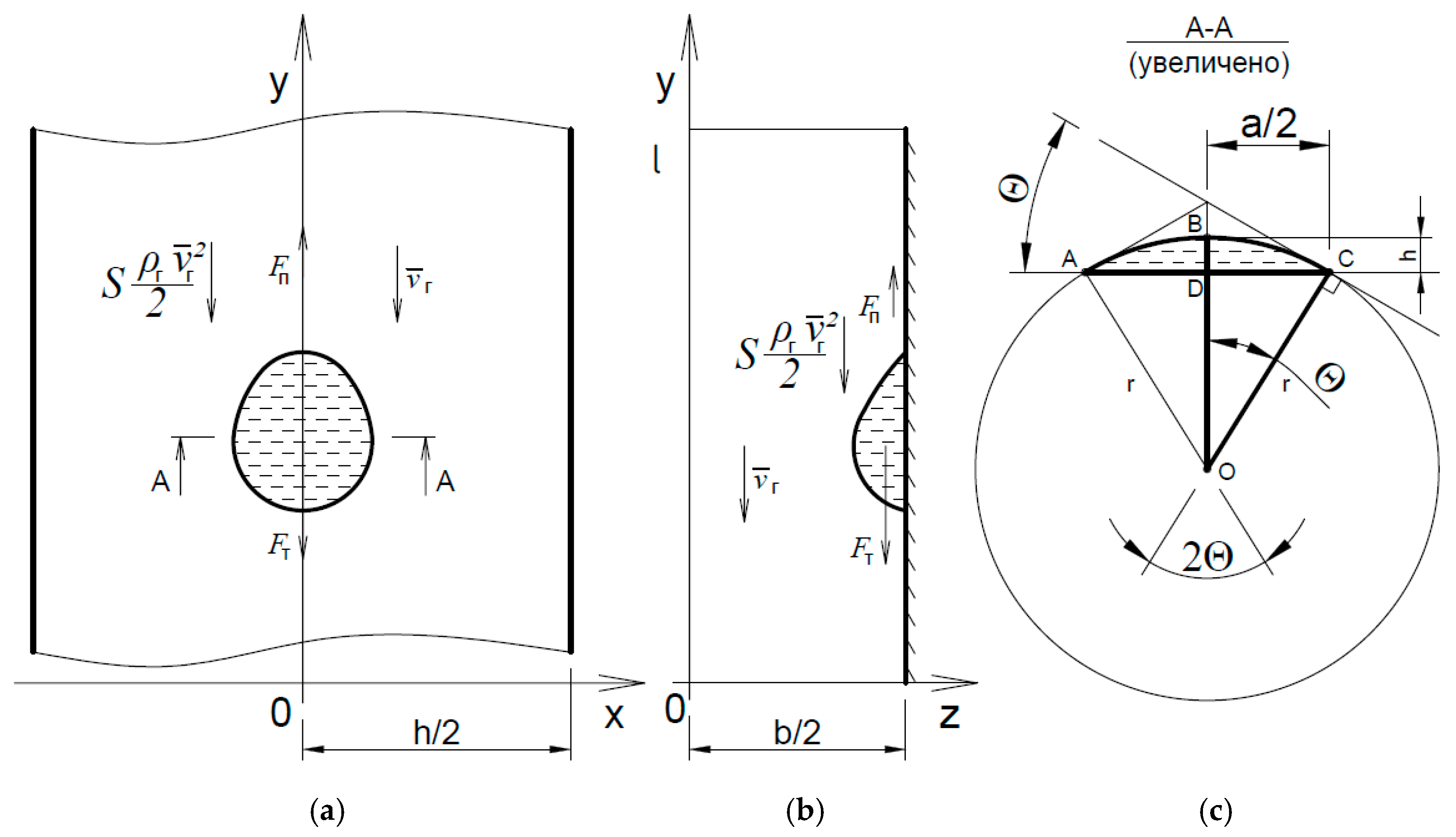
Figure 9.
Dependence of the relative evaporation area coefficient on the marginal wetting angle.
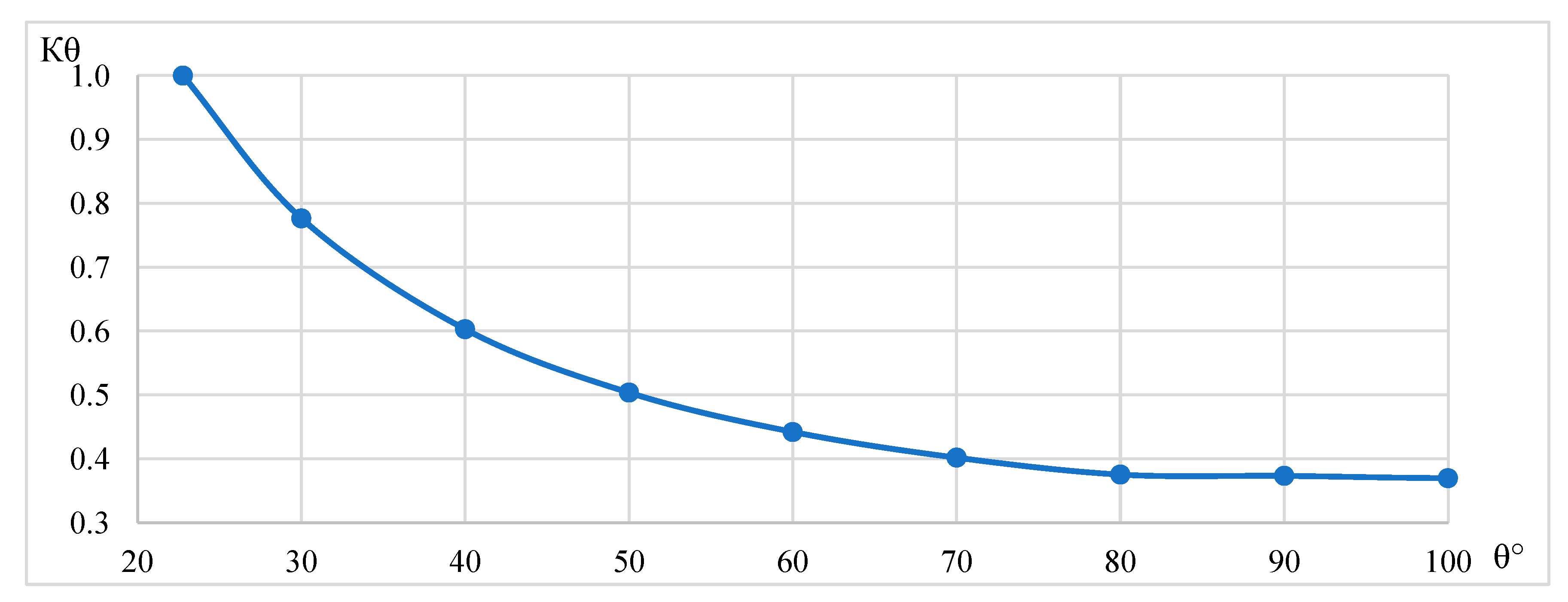
Figure 10.
Wetting edge angle of water-polycarbonate.
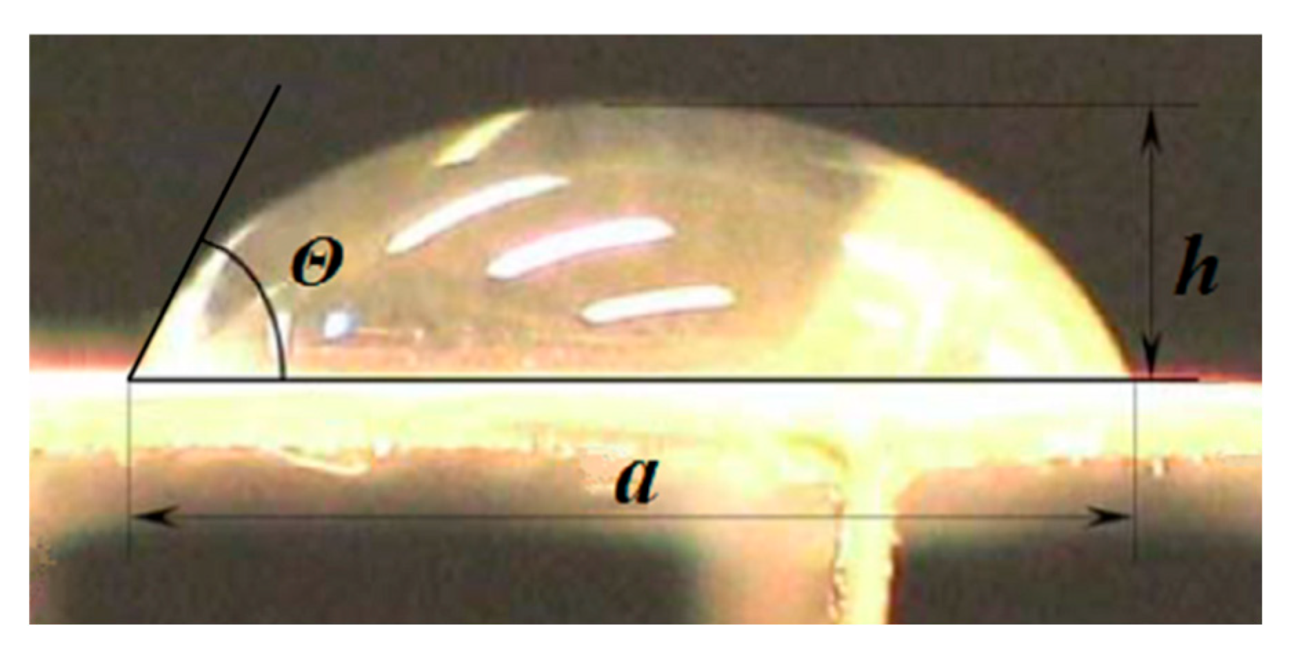
Figure 11.
Dependence of the jet base length on the wetting edge angle and air flow velocity in the tube.
Figure 11.
Dependence of the jet base length on the wetting edge angle and air flow velocity in the tube.
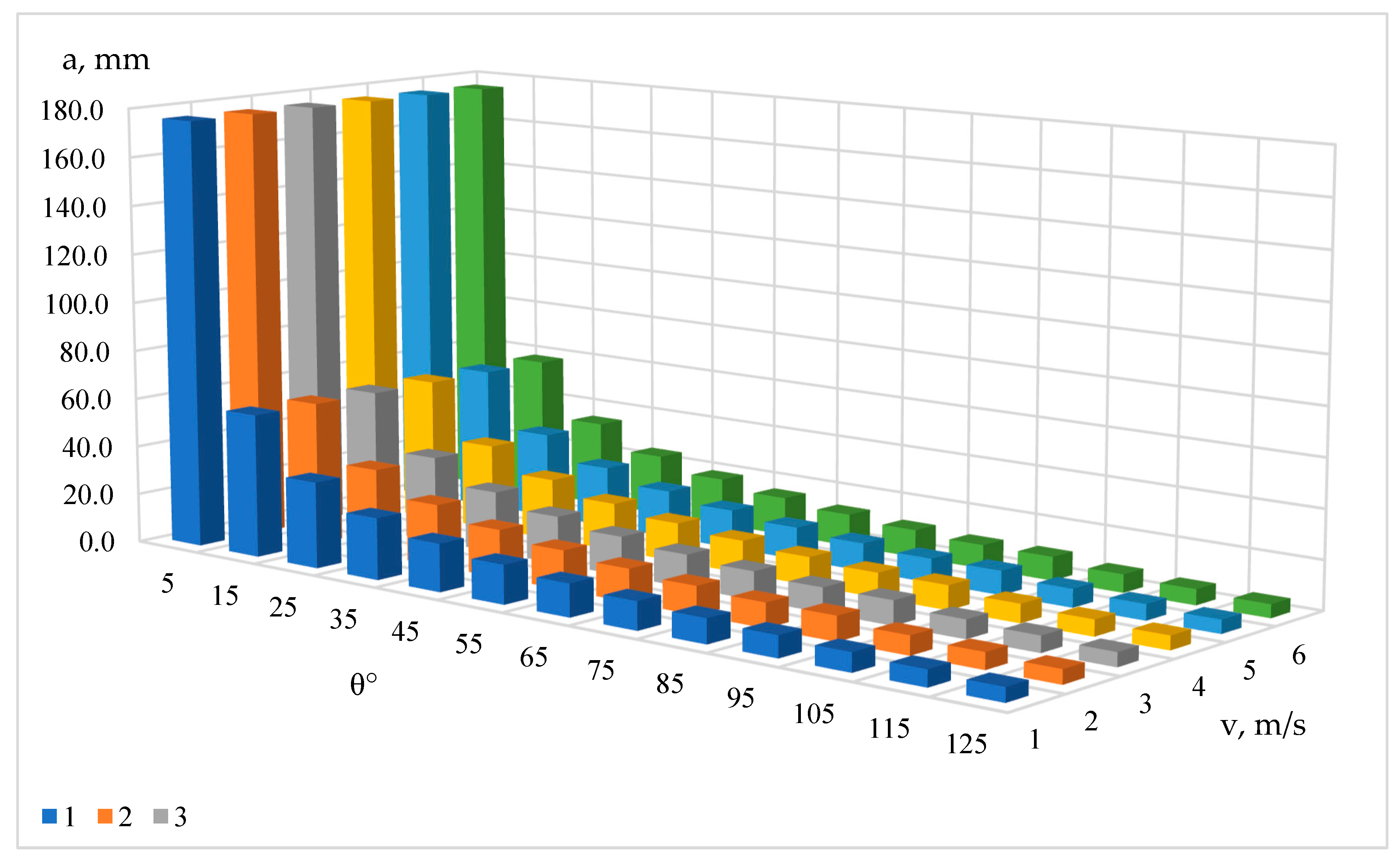
Figure 12.
Graph of temperature drop as a function of water flow rate: I - zone of water deficit; II - zone of optimal functioning; III - zone of pronounced splash formation.
Figure 12.
Graph of temperature drop as a function of water flow rate: I - zone of water deficit; II - zone of optimal functioning; III - zone of pronounced splash formation.
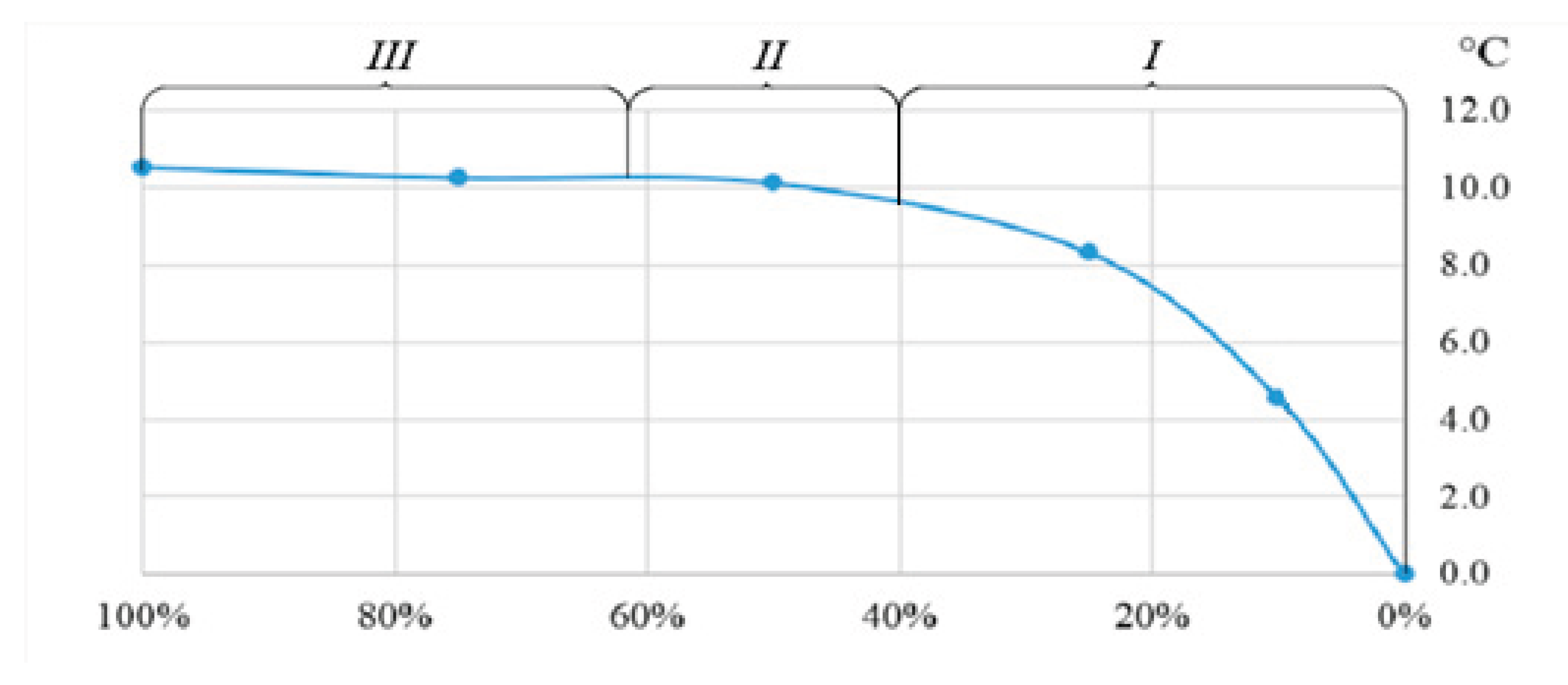

Table 1.
Comparative analysis of heat exchangers.
| Comparison Criteria | Type of Heat Exchanger | |||
|---|---|---|---|---|
| Recuperative | Regenerative Rotary |
With Intermediate Heat Transfer Medium | Based on Heat Pipes | |
| Heat efficiency | 30-70% | 60-80% | 30-40% | 80-95% |
| Compactness | + | + | - | - |
| Operation without mixing air streams | + | - | + | + |
| No moving parts | + | - | - | + |
| Decentralization | - | - | + | + |
| High capacity | + | + | + | - |
Table 2.
Test results of the heat recovery system in cooling mode.
| Outdoor air parameters | |||
| to, °С | φo, % | do, g/kg dry air | |
| 30.4 | 31.2 | 9.09 | |
| Air parameters at the unit outlet | |||
| ts, °С | Δt, °С | φs, % | ds, g/kg dry air |
| 27.43 | 6.3 | 40.7% | 13.48 |
Table 3.
Dependence of temperature drop on water flow rate.
| Water flow rate, % | 100 | 75 | 50 | 25 | 10 | 0 |
| Average value of temperature at the unit outlet, °С | 21.9 | 22.1 | 22.3 | 24.1 | 27.8 | 32.4 |
| Decrease in temperature, °C | 10.5 | 10.3 | 10.1 | 8.3 | 4.6 | 0.0 |
| Deviation, % | 0.0 | 2.5 | 3.8 | 20.9 | 56.7 | 100.0 |
Disclaimer/Publisher’s Note: The statements, opinions and data contained in all publications are solely those of the individual author(s) and contributor(s) and not of MDPI and/or the editor(s). MDPI and/or the editor(s) disclaim responsibility for any injury to people or property resulting from any ideas, methods, instructions or products referred to in the content. |
© 2025 by the authors. Licensee MDPI, Basel, Switzerland. This article is an open access article distributed under the terms and conditions of the Creative Commons Attribution (CC BY) license (https://creativecommons.org/licenses/by/4.0/).
Copyright: This open access article is published under a Creative Commons CC BY 4.0 license, which permit the free download, distribution, and reuse, provided that the author and preprint are cited in any reuse.


