
Submitted:
15 October 2025
Posted:
16 October 2025
You are already at the latest version
Abstract
This study presents an innovative design for a sustainable Coupled Solar Ventilation-Evaporative Cooling (SVEC) system. It utilizes a wall solar chimney to generate natural ventilation, directing waste hot, dry air through a humid hay bed on the roof to induce evaporation and create a cooling effect. The resulting cold is transferred via a thermally conductive plate, while a membrane condenser recovers moisture for reusing it. A mathematical model governing the evaporation process permits to analyse steady-state cooling performance. Simulations explore how inlet air temperature, airflow rate, humidity ratio and hay moisture content influence cooling, revealing optimal conditions for enhanced performance.
Keywords:
evaporative cooling
; solar energy
; air flow rate
; air humidity ratio
; moisture content
; sustainability
1. Introduction
Sustainability, energy savings and environment preservation [1,2,3] in air conditioning, cooling ventilation and drying systems [4,5,6,7,8,9,10] become more and more interesting topics during the last decades. Renewable energies, such as solar energy, strongly help to reduce the need for fossil energy sources. This can lower greenhouse gas emissions and costs for residential and industrial buildings [11,12,13]. Solar-assisted evaporative cooling and natural ventilation systems [14,15,16,17] can save energy and improve indoor thermal comfort and air quality.
Solar evaporative cooling uses the heat of the sun to evaporate water, which cools the air. This process is particularly efficient in hot and dry climates. On the other hand, solar ventilation uses solar energy to create airflow in buildings. This process carries out the renewal of fresh air and the remove of hot air for the condoned space. This enhances the indoor thermal comfort and air quality. When these systems are combined, they can use solar energy to improve both cooling and ventilation. This literature review presents how solar-powered evaporative cooling and solar natural ventilation and can be coupled to work efficiently together. The recent progress and important findings carried out by the most relevant research works done in the last three years are highlighted.
Saifi et al. [18] carried out an experimental and a numerical study investigating a passive solar cooling system, which includes a wind catcher, evaporative cooling and a solar chimney, to lower temperatures in a room in the region of Ouargla, Algeria. Tests showed that the investigated system increased air flow and reduced room temperatures by 3–7 °C, proving its effectiveness in keeping condoned spaces thermally comfortable and using less energy. Heidari et al. [19] carried out a numerical investigation examining a natural cooling system for homes using a horizontal windcatcher and evaporative cooling. The researchers used the ANSYS Fluent software for airflow modeling and the MATLAB software to check the working effectiveness of the proposed system. They found that the proposed system is able to ensure the indoor thermal comfort using less electricity in hot weather in Tehran compared to conventional air conditioners. Also, they produced guidelines for window openings in order to improve the system’s performance. They found that the horizontal windcatcher reduced energy use by 50% compared to vertical ones.
Jafari and Kalantar [20] addressed the problem of high fossil fuel use and energy consumption in buildings, focusing on improving natural cooling. They numerically tested a system using a windcatcher, three solar chimneys and a water spray system (WSS) to cool and humidify air in a multi-story building in a hot, dry climate. Using CFD simulations, the researchers found that the WSS can reduce temperatures by 6–12 °C and increase humidity by 80% on the third floor. This permits to enhance the proposed cooling system’s efficiency and comfort even without wind. Abbas A. Ghaffouri and Jubear [21] carried out a numerical analysis based on a simulation model for a hybrid cooling and ventilation system using the software ANSYS FLUENT 19.2. The investigated system has two floors, each with a 1 m³ room connected to a vertical solar chimney of 3m height and a northward evaporative cooler. The air intended for the cooler comes from a heat exchanger situated in 17 m underground. The investigation assesses the influence of some factors such as temperature, humidity and solar radiation on the performance of the proposed system in the region of Kut, Iraq. Results show that the proposed system can lower room temperatures by 10–15 °C and increase humidity by 20% compared to the outside.
Garcia et al. [22] evaluated a low-profile cross-ventilated (LPCV) barn with evaporative cooling pads in order to reduce heat stress in lactating dairy cows. The researchers collected 5,712 records of air temperature and humidity over 238 days. They calculated the temperature-humidity index (THI) and the enthalpy to assess the system’s effectiveness. The results showed that the barn maintained a temperature difference up to −12 °C compared to outside. This significantly reduces the heat stress. The cows spent more time in comfortable conditions, with only 5% of time above 25 °C inside, compared to 33% outside. The proposed LPCV system proved its effectiveness for dairy farming in hot and humid climates. Soto et al. [23] investigated the effectiveness of a natural ventilation system with passive cooling using solar chimneys under different climates. Using an experimentally validated simulation tool, the researchers assessed the working effectiveness of the system under Spanish and European cities climates. Results showed good performance under hot and dry climates such as Madrid and moderate performance under warmer regions like Alicante. A lower efficiency is noticed under colder and humid places like Bilbao and Burgos. The investigation highlighted the potential energy-saving of the considered system for cooling indoor spaces, depending on the local climate.
2. Innovative Design
2.1. Description
Figure 1 illustrates an innovative design for a sustainable coupled ventilation-evaporative cooling system powered by solar energy. The proposed system is called Coupled Solar Ventilation-Evaporative cooling (SVEC) System.
This SVEC system utilizes the water-evaporation process within humid hay bed, situated as a roof, to generate a cooling effect when relatively dry and hot air passes through it. A solar wall chimney produces both natural ventilation within the conditioned space and a relatively hot and dry air as waste air at the outlet of the chimney. The natural ventilation not only drives the air but also enhances convection within the conditioned space. The waste hot, relatively dry air, passes through a membrane condenser for further dehumidification, ensuring it meets, as process air, the optimal moisture range for effective evaporative cooling (optionally, the obtained condensate water can be treated to produce potable water).
Then, the hot and dry process air passes through the humid hay bed in order to drive the evaporation process, inducing the cooling effect. Moisture from the hay bed is absorbed from the waste air, recovered at the hay bed’s outlet using a membrane condenser and returned then to the hay bed to be continuously wetted. The waste dry air is then evacuated to the outlet of the system. The hay bed is insulated at the top with cellulose insulation to enhance the energetic performance of the hay bed and avoid to be heated by solar energy. A thermally conductive inner roof, at the bottom of the hay bed, is used to efficiently transfer cold via convection to a cellulose-insulated conditioned room. Optimizing the airflow rate, air humidity ratio and hay moisture content improves the evaporative-cooling efficiency of the proposed design.
2.2. Design Key Features
This innovative SVEC system utilizes solar energy to create sustainable coupled passive and active cooling through a water-evaporation process in hay bed placed on the roof. This system offers an efficient and sustainable approach to cooling, using renewable resources for enhanced indoor comfort.
The main key features of such a design can be summarized into 5 points:
- Hay bed: Uses natural materials for cooling via evaporation. Optimized for airflow, air humidity ratio and hay moisture content;
- Solar-powered ventilation: A solar wall chimney induces hot and dry airflow through the hay bed;
- Insulation and convection: Cellulose insulation for the outer roof and thermally conductive inner roof for efficient cold transfer;
- Moisture recovery: A membrane condenser recovers the moisture from the bed outlet air and returns it to the hay bed to safe water. Moreover, another membrane condenser recovers the moisture from the relatively dry inlet air to further dehumidify it;
- Natural airflow: Promotes ventilation and thermal comfort within the conditioned space;
- Controlled inlet air flow: A flow regulator is used to control the inlet air flow rate.
2.2. Design Key Features
The main key benefits of such a design can be also summarized into 5 points:
- Sustainable: Eco-friendly materials and processes which minimizes environmental impact;
- Energy efficient: Reduces energy consumption through the use of solar energy;
- Cost-effective: Low operational costs due to free solar;
- Improved indoor air quality: Improves thermal comfort within the conditioned space based on enhanced convection, due to ventilation and cooling effect, due to the evaporation process;
- Scalable: Adaptable to various building sizes and climates.
2.3. Claims
- A sustainable Coupled Solar Ventilation-Evaporative Cooling (SVEC) system comprising:
- Roof-mounted hay bed using a water-evaporation process to generate cooling effect when relatively dry and hot air passes through it;
- Solar wall chimney for inducing natural ventilation and enhancing convection within the conditioned space;
- Cellulose-insulated conditioned room;
- Membrane condenser for recovering moisture from the humid air at the hay bed’s outlet. The recovered moisture is reintroduced into the hay bed;
- Membrane condenser for recovering moisture from the inlet process air to further dry it. The condensate water can be optionally treated to produce potable water.
- 2.
- The sustainable SVEC system of claim 1, wherein the hay bed is insulated at the top with cellulose insulation and using a thermally conductive inner roof at the bottom to efficiently transfer cold via convection to the cellulose-insulated conditioned room.
- 3.
- The sustainable SVEC system of claim 1, wherein the solar wall chimney uses solar energy to induce natural ventilation, reducing reliance on fossil energy sources and minimizing environmental impact.
- 4.
- The sustainable SVEC system of claim 1, wherein optimizing the airflow rate, air humidity ratio and hay moisture content improves the cooling effect of the system.
3. Mathematical Modeling
3.1. Assumptions
Some principal justified assumptions should be taken into consideration to elaborate the global mathematical model describing the evaporation through the humid hay packed bed: Uniform temperature distribution in the hay bed.
- Uniform temperature distribution in the hay bed: In our proposed system, hot air flows through the hay-packed bed, where evaporation cools the hay bed. If the airflow is well-distributed, spatial temperature differences inside the bed remain small. This makes reasonable the assumption of uniform temperature. In practical applications, engineering designs often ensure proper airflow distribution to maintain efficiency which supports this assumption;
- Steady-state conditions: The system is assumed to operate continuously without significant variations over time. This means that temperature and humidity levels remain stable. Since many industrial and applied research works focus on steady performance rather than transient fluctuations, this assumption simplifies the analysis without significantly affecting accuracy;
- Constant air properties: Variations in air density, specific heat and other thermophysical properties due to temperature and humidity changes are often small enough to be negligible. Using average values is common in engineering models as the errors introduced are minor compared to the overall uncertainties in realistic conditions;
- No resistance to heat transfer: This is justified by the fact that heat transfer occurs instantaneously since the hay bed has high surface area and good thermal contact with the passing air. In many practical designs, the heat exchange process is efficient enough that additional resistance effects have minimal impact on the overall system behavior;
- No condensation or heat generation: The system is designed in the way that air remains unsaturated which prevents condensation inside the hay bed. No additional heat sources such as chemical reactions or external heaters affect the thermal balance. Thus, it is reasonable to exclude internal heat generation in the model.
These assumptions provide a realistic and practical simplification of the system while maintaining sufficient accuracy for engineering design and performance evaluation. This makes a general model both practical and sufficient for analyzing a room cooled by evaporation in applied research and industrial system design, where the focus is on efficient, functional and easy-to-implement solutions rather than highly detailed simulations based on complex differential equations.
3.2. Modeling
3.2.1. Air-Hay Energy Transfer
The air-hay energy transfer is governed by the following equation:
With the air mass flow rate is expressed as:
The air flow rate is expressed as:
The air velocity in the hay packed bed is given as:
The pressure difference driving the air flow in the chimney is given as:
The pressure drop due to the flow resistance induced by the hay packed bed is given by the Ergun equation [24] for both laminar and turbulent flow in porous media:
With is the superficial air velocity (air velocity before entering the packed bed; at the outlet of the solar chimney). It is given as:
The air density is given as:
3.2.2. Energy Needed for Evaporation of Water in Hay Bed
The energy needed for evaporation of water in hay bed is governed by the following equation:
With the actual water mass change due to the evaporation is expressed as:
With the potential water evaporation rate is expressed as:
And the water supply rate is considered equal to the potential water evaporation rate is steady-state. The water evaporation is balanced by the water supply:
The mass of hay is expressed as:
3.2.2. Final Temperature of Hay
The final temperature of the hay is governed by the following equations:
4. Simulation Results and Discussions
The simulation focuses on the steady state evaporative cooling performance of the proposed system.
4.1. Simulation Procedure
The simulation follows these steps:
- Parameter definition;
- Initial hay temperature;
- Inlet Air humidity Ratio;
- Moisture content;
- Airflow rate;
- Bed dimensions;
- Physical properties such as latent heat, specific heat and densities.
- 2.
- Bulk property calculations;
- Hay bed density, total mass, and water content are determined.
- 3.
- Energy balance analysis;
- The air mass flow rate, heat transfer from air to hay and the energy required for moisture evaporation are computed.
- 4.
- Simulation execution.
- The model is run for air temperatures between 40–60 °C and hay moisture contents between 0.005–0.015 kg water/kg dry hay;
- 2D and density plots visualize temperature variations.
All numerical results are obtained using the following simulation data, with justifications provided for the key simulation parameters.

Table 1.
Simulation data.
| Variable | Value | |
| Initial temperature of hay Th,i | 30 °C | |
| Justification: Although the study assumes steady-state conditions, initial hay temperature is used as a reference for energy balance calculations, not as an indication of a transient process. It represents the hay’s temperature before interacting with the airflow and serves as a baseline for determining the final equilibrium temperature. | ||
| Air temperature | [40 °C; 60 °C] | |
| Justification: The most suitable air temperature range for effective evaporative cooling is generally 25–40 °C. However, in our design, the air is supplied by a solar chimney to ensure proper ventilation. Since the air temperature in a solar chimney is naturally higher than 25–40 °C, a range of 40–60 °C remains suitable only if two key conditions are met: (1) the air must be sufficiently dry and (2) the hay must be continuously wetted to sustain effective evaporative cooling. These 2 conditions should be ensured by the proposed design. | ||
| Moisture content of hay Xw | 0.006 ; 0.01; 0.014 kg water/kg dry hay | |
| Justification: Practical values for effective evaporative cooling, ensuring sufficient moisture for heat absorption while preventing excessive saturation. These values align with typical hay moisture levels and the 40–60 °C air from the solar chimney. | ||
| Humidity ratio of the air ωa | 0.002; 0.004; 0.006 kg water/kg dry air | |
| Justification: These values are reasonable and align with real atmospheric conditions, particularly in dry and semi-dry regions. In reality, very dry air, such as that found in desert climates, can have a humidity ratio as low as 0.002 kg/kg, while typical ambient air in many regions ranges between 0.004 and 0.006 kg/kg, especially in warm conditions. | ||
| Flow rate of air FR | 0.25 ; 0.35 ; 0.45 m3/s | |
| Justification: Ensure an optimal balance between evaporative cooling and ventilation. The lower value: 0.25 m³/s allows more time for moisture evaporation which maximizes cooling. The higher value: 0.45 m³/s enhances airflow and heat removal. The intermediate value: 0.35 m³/s provides a balanced approach. | ||
| Porosity of hay packed bed ε | 0.85 | |
| Justification: Ensure a balance between airflow and heat transfer efficiency. Higher porosity than 0.85 facilitates better ventilation at the expense of weaker heat exchange. While, lower porosity than 0.85 enhances heat exchange but may restrict airflow which potentially limits moisture removal and heat exchange. | ||
| Specific heat of hay Cp,h | 1.8 kJ/kg hay | |
| Density of dry hay ρh | 400 kg dry hay/m3 hay | |
| Specific heat of air Cp,a | 1.006 kJ/kg°K | |
| Density of air ρa | 1.11 kg/m3 | |
| Length of hay packed bed L | 2 m | |
| Cross-sectional area of hay packed bed A | 0.01 m | |
| Latent heat of evaporation He | 2260 kJ/kg | |
Figure 2 presents the variation of hay temperature as a function of inlet air temperature for three different air flow rates: 0.25 m³/s, 0.35 m³/s and 0.45 m³/s. The initial hay temperature is 30 °C, with a hay moisture content of 0.01 kg water/kg dry hay and an air humidity ratio of 0.004 kg water/kg dry air.
For the lowest air flow rate (0.25 m³/s), the hay temperature remains 30 °C at lower inlet air temperatures but decreases once a certain threshold (43.5 °C) is reached, indicating the start of evaporative cooling to reach a hay temperature around 28.2 °C. At 0.35 m³/s, the cooling effect is more pronounced, leading to a further reduction in hay temperature (27.5 °C), demonstrating that increased airflow enhances heat and mass transfer. The highest air flow rate (0.45 m³/s) results in the most significant hay temperature drop (26.8 °C).
Thus greater airflow increases the rate of moisture evaporation, thereby enhancing cooling efficiency. If the inlet air temperature is too low, there may not be enough energy to trigger significant evaporation. However, once it surpasses the necessary threshold, the process becomes more effective, allowing moisture to be carried away and cooling to take place efficiently.
Figure 3 presents a plot serving as a tool for presizing or optimizing the proposed cooling system as well as precisely selecting the operating parameters, based on inlet air temperature and airflow rate. The plot reveals three distinct regions of interplay. In the leftmost red region (low air temperature), hay remains at 30 °C, indicating no evaporative cooling effect due to insufficient energy for evaporation. Moving towards the central gradient region, a transition occurs as the inlet air temperature rises above approximately 43 °C, leading to gradual hay cooling. This region highlights the balance between heat transfer and evaporation. In the top-right purple and blue region (high air temperature and high airflow), the most significant cooling is achieved, as increased airflow enhances moisture removal, dropping hay temperature below 27 °C. By analyzing these regions, designers can fine-tune the proposed system to achieve efficient evaporation cooling.
Figure 4 presents the variation of hay temperature as a function of inlet air temperature for three different hay moisture contents: 0.006 kg water/kg dry hay, 0.01 kg water/kg dry hay, and 0.014 kg water/kg dry hay. The air flow rate is 0.35 m³/s, with an air humidity ratio of 0.004 kg water/kg dry air. For the lowest moisture content (0.006 kg water/kg dry hay), the hay temperature remains constant slightly less than 30 °C, indicating that the evaporative cooling does not occur. At 0.01 kg water/kg dry hay, the hay temperature stays at 30 °C at lower inlet air temperatures but decreases after a threshold temperature is reached, showing the start of evaporation, which leads to a final hay temperature of approximately 27.5 °C. In the case of the highest moisture content (0.014 kg water/kg dry hay), the cooling effect is even more pronounced, causing the hay temperature to drop further to around 26 °C.
Thus, higher moisture content enhances evaporative cooling, as more water is available for evaporation. If the inlet air temperature is not high enough, evaporation does not start, and the hay temperature remains unchanged. However, once the inlet air temperature crosses the necessary threshold, moisture removal begins, leading to a noticeable temperature reduction.
Figure 5 presents a plot serving as a tool for presizing or optimizing the proposed cooling system as well as precisely selecting the operating parameters, based on inlet air temperature and air humidity ratio.
In the upper-left region (high moisture content and low inlet air temperature), hay temperature remains high around 30 °C due to limited evaporative cooling, indicating inefficient drying conditions. In the central region, a transition occurs as increasing air temperature enhances heat transfer, leading to a decrease in hay temperature, suggesting improved evaporative cooling efficiency. In the lower region (low moisture content and moderate-to-high inlet air temperature), hay temperature stabilizes between 28-29 °C, indicating effective balance between heat and mass transfer. In the upper-right region (high moisture content and high inlet air temperature), a sharp cooling effect to around 26 °C is observed, driven by enhanced evaporation, demonstrating a critical threshold where higher air temperatures significantly accelerate moisture loss.
Figure 6 illustrates the variation of hay temperature as a function of inlet air temperature for three different air humidity ratios: 0.002 kg water/kg dry air, 0.004 kg water/kg dry air, and 0.006 kg water/kg dry air. The initial hay temperature is 30 °C, with a hay moisture content of 0.01 kg water/kg dry hay and an air flow rate of 0.35 m³/s.
For the lowest air humidity ratio (0.002 kg water/kg dry air), the hay temperature remains at 30 °C for lower inlet air temperatures but starts to decrease beyond a threshold of about 48 °C, reaching approximately 26.7 °C. This indicates the start of evaporative cooling. At an air humidity ratio of 0.004 kg water/kg dry air, the cooling effect is slightly reduced, with the hay temperature decreasing to around 27.5 °C. However, for the highest air humidity ratio (0.006 kg water/kg dry air), the hay temperature remains at 30 °C across all inlet air temperatures, indicating that evaporative cooling does not take place.
Thus, a lower air humidity ratio enhances evaporative cooling, as drier air can absorb more moisture from the hay, leading to a greater temperature drop. When the air humidity ratio is lower, the cooling is most effective, as the air has a higher capacity to carry away moisture. As the air humidity ratio increases, the potential for moisture removal decreases, reducing the cooling effect. At higher air humidity ratio, the air is nearly saturated, preventing further evaporation and resulting in no cooling. This confirms that evaporative cooling is dependent on the difference between the moisture content of the hay and the surrounding air, with drier air promoting greater heat and mass transfer.
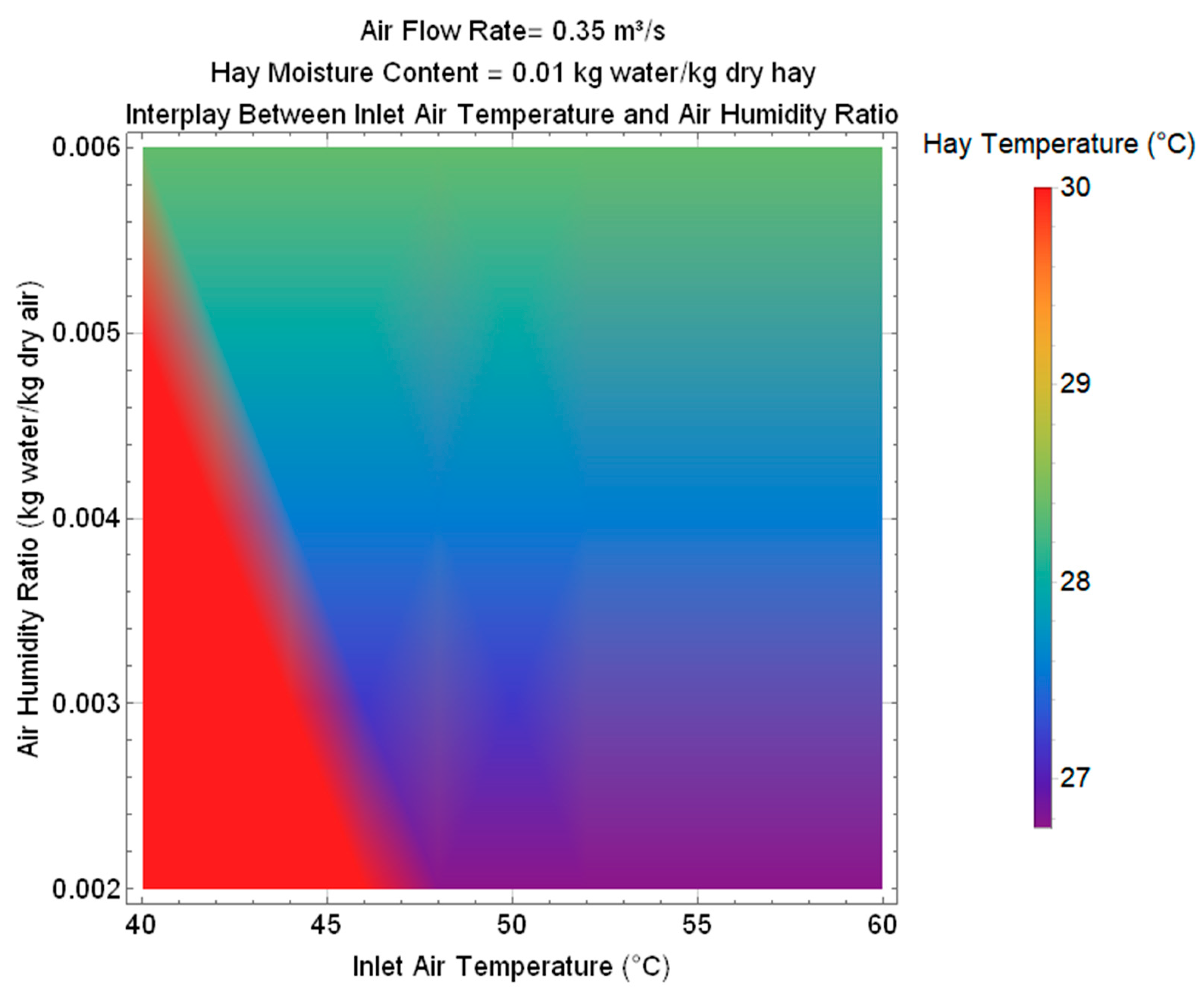
Figure 7 presents a plot serving as a tool for presizing or optimizing the proposed cooling system as well as precisely selecting the operating parameters, based on inlet air temperature and air humidity ratio.
The lower-right region (high temperature and low humidity) illustrates how dry air enhances evaporative cooling, allowing hay temperatures to drop to approximately 26.5 °C. In contrast, the upper-right region (lower temperature and higher humidity) indicates that increased air humidity reduces evaporation, resulting in a more moderate hay temperature. The middle transition zone, marked by a blue-to-purple gradient, represents a gradual decline in the evaporative cooling effect as humidity increases. The distinct triangular red zone at the left zone highlights that the inlet air temperature at which evaporative cooling begins is lower when the air humidity ratio increases. However, under these higher humidity conditions, the cooling effect is less pronounced.
5. Conclusions
The main results of this research work can be concluded into 4 principal points:
- Innovative sustainable design for a Coupled Solar Ventilation-Evaporative Cooling (SVEC) System is developed;
- Numerical performance analysis is carried out to assess the evaporative cooling effect of the proposed design:
- For a fixed hay moisture content and air humidity ratio around 0.01 kg water/kg dry hay and 0.004 kg water/kg dry air respectively, when the air flow rate increases as 0.25 m3/s, 0.35 m3/s and 0.45 m3/s, the hay temperature decreases from 30 °C to reach 28.2 °C, 27 °C and 26.9 °C respectively when the inlet air temperature exceeds the threshold of 43.5 °C. A plot is provided to serve as a tool for presizing or optimizing the proposed cooling system as well as precisely selecting the operating parameters, based on inlet air temperature and airflow rate;
- For a fixed air flow rate and air humidity ratio around 0.35 m3/s and 0.004 kg water/kg dry air respectively, the hay temperature remains slightly below 30 °C when the hay moisture content is 0.006 kg water/kg dry hay. The hay temperature decreases to reach 27.5 °C and 26 °C when the hay moisture content is 0.01 kg water/kg dry hay and 0.014 kg water/kg dry hay respectively when the inlet air temperature exceeds the threshold of 43.5 °C and 52.5 °C respectively. A plot is provided to serve as a tool for presizing or optimizing the proposed cooling system as well as precisely selecting the operating parameters, based on inlet air temperature and hay moisture content;
- For a fixed air flow rate and hay moisture content around 0.35 m3/s and 0.01 kg water/kg dry hay respectively, The hay temperature decreases to reach 26.8 °C and 27.5 °C for an air humidity ratio around 0.002 kg water/kg dry air and 0.004 kg water/kg dry air respectively when the inlet air temperature exceeds the threshold of 48 °C and 43.5 °C respectively. The hay temperature remains slightly below 30 °C when the air humidity ratio is around 0.006 kg water/kg dry air. A plot is provided to serve as a tool for presizing or optimizing the proposed cooling system as well as precisely selecting the operating parameters, based on inlet air temperature and air humidity ratio.
Author Contributions
Conceptualization, F.A. and R.N.; methodology, F.A.; software, R.N.; validation, F.A., C.A. and R.N.; formal analysis, F.N.; investigation, F.A.; resources, F.N.; data curation, C.A.; writing—original draft preparation, R.N.; writing—review and editing, F.A.; visualization, C.A.; supervision, F.A.; project administration, F.N.; funding acquisition, F.A. All authors have read and agreed to the published version of the manuscript.
Funding
This research received no external funding.
Acknowledgments
The authors are thankful to the Deanship of Graduate Studies and Scientific Research at University of Bisha for supporting this work through the Fast-Track Research Support Program.
Conflicts of Interest
The authors declare no conflicts of interest.
Abbreviations
The following abbreviations are used in this manuscript:
| Variable | Description | Unit |
| A | Area of the cross section | m2 |
| Cp | Specific Heat | J/kgK |
| d | Diameter | m |
| FR | Flow rate | m3/s |
| g | Gravitational acceleration | m/s2 |
| H | Latent heat | J/kg |
| h | Vertical chimney height | m |
| L | Length | m |
| m | Mass | kg |
| Mass flow rate | kg/s | |
| Actual mass change | kg/s | |
| P | Pressure | N/m2 |
| Q | Heat | J |
| R | Universal gas constant | J/kg.K |
| T | Temperature | K |
| X | Moisture content | kg water/kg dry hay |
| Bed porosity | - | |
| Pressure difference | N/m2 | |
| Dynamic viscosity | Ns/m2 | |
| ρ | Density | m3/kg |
| Air Humidity Ratio | kg water/kg dry air | |
| Subscript | Description | |
| a | Air | |
| amb | Ambient | |
| atm | Atmospheric | |
| b | Bed | |
| c | Chimney | |
| evap | Evaporation | |
| f | Final | |
| h | Hay | |
| i | Initial | |
| p | Particle | |
| spl | Supply | |
| t | Transferred energy from air to hay | |
| w | Water |
References
- Sioshansi, F. Energy, Sustainability and the Environment: Technology, Incentives, Behavior; Elsevier: Amsterdam, The Netherlands, 2011. [Google Scholar]
- Wasewar, K.L.; Rao, S.N. Sustainable engineering, energy, and the environment. In Apple Academic Press eBooks; 2022. [CrossRef]
- Kim, J.; Chen, Z. Trends in environmental sustainability and green energy. In Springer Proceedings in Earth and Environmental Sciences; Springer: Cham, Switzerland, 2023. [Google Scholar] [CrossRef]
- Hughes, B.R.; Chaudhry, H.N.; Ghani, S.A. A review of sustainable cooling technologies in buildings. Renew. Sustain. Energy Rev. 2011, 15, 3112–3120. [Google Scholar] [CrossRef]
- Spentzou, E.; Cook, M.J.; Emmitt, S. Low-energy cooling and ventilation refurbishments for buildings in a Mediterranean climate. Archit. Eng. Des. Manag. 2021, 18, 473–494. [Google Scholar] [CrossRef]
- Hydes, K.; Fosket, J. Sustainable heating ventilation and air conditioning. In Springer eBooks; Springer: New York, NY, USA, 2013; pp. 653–665. [Google Scholar] [CrossRef]
- Eicker, U. Low Energy Cooling for Sustainable Buildings; John Wiley & Sons: Chichester, UK, 2009. [Google Scholar]
- Asim, N.; Badiei, M.; Mohammad, M.; Razali, H.; Rajabi, A.; Haw, L.C.; Ghazali, M.J. Sustainability of heating, ventilation and air-conditioning (HVAC) systems in buildings—An overview. Int. J. Environ. Res. Public Health 2022, 19, 1016. [Google Scholar] [CrossRef] [PubMed]
- Rabhi, K.; Ali, C.; Nciri, R.; Bacha, H.B. Novel design and simulation of a solar air-conditioning system with desiccant dehumidification and adsorption refrigeration. Arab. J. Sci. Eng. 2015, 40, 3379–3391. [Google Scholar] [CrossRef]
- Ali, C.; Attyaoui, S.; Nasri, F.; Bacha, H.B. Heat and mass transfer in a solar tunnel dryer: Modelling and simulation. Int. Rev. Mech. Eng. 2012, 6, 810–817. [Google Scholar]
- Dalei, N.N.; Gupta, A. Adoption of renewable energy to phase down fossil fuel energy consumption and mitigate territorial emissions: Evidence from BRICS group countries using panel FGLS and panel GEE models. Discov. Sustain. 2024, 5. [Google Scholar] [CrossRef]
- Hossain, M.F. Estimation of global solar energy to mitigate world energy and environmental vulnerability. In CRC Press eBooks; CRC Press: Boca Raton, FL, USA, 2021; pp. 13–40. [Google Scholar] [CrossRef]
- Holechek, J.L.; Geli, H.M.E.; Sawalhah, M.N.; Valdez, R. A global assessment: Can renewable energy replace fossil fuels by 2050? Sustainability 2022, 14, 4792. [Google Scholar] [CrossRef]
- Nanda, A.K.; Panigrahi, C.K. A state-of-the-art review of solar passive building systems for heating or cooling purposes. Front. Energy 2016, 10, 347–354. [Google Scholar] [CrossRef]
- Prieto, A.; Knaack, U.; Auer, T.; Klein, T. COOLFACADE: State-of-the-art review and evaluation of solar cooling technologies on their potential for façade integration. Renew. Sustain. Energy Rev. 2019, 101, 395–414. [Google Scholar] [CrossRef]
- Khanal, R.; Lei, C. Solar chimney—A passive strategy for natural ventilation. Energy Build. 2011, 43, 1811–1819. [Google Scholar] [CrossRef]
- Maghrabie, H.M.; Abdelkareem, M.A.; Elsaid, K.; Sayed, E.T.; Radwan, A.; Rezk, H.; Wilberforce, T.; Abo-Khalil, A.G.; Olabi, A. A review of solar chimney for natural ventilation of residential and non-residential buildings. Sustain. Energy Technol. Assess. 2022, 52, 102082. [Google Scholar] [CrossRef]
- Saifi, N.; Baadi, A.; Ghedamsi, R.; Guerrout, A.; Settou, N. An experimental study and numerical simulation of natural ventilation in a semi-arid climate building using a wind catcher with evaporative cooling system and solar chimney. J. Build. Eng. 2024, 108475. [Google Scholar] [CrossRef]
- Heidari, S.; Poshtiri, A.H.; Gilvaei, Z.M. Enhancing thermal comfort and natural ventilation in residential buildings: A design and assessment of an integrated system with horizontal windcatcher and evaporative cooling channels. Energy 2024, 289, 130040. [Google Scholar] [CrossRef]
- Jafari, S.; Kalantar, V. Numerical simulation of natural ventilation with passive cooling by diagonal solar chimneys and windcatcher and water spray system in a hot and dry climate. Energy Build. 2021, 256, 111714. [Google Scholar] [CrossRef]
- Ghaffouri, A.A.; Jubear, A.J. Numerical analysis of a passive ventilation system coupled with a hybrid cooling system. Mater. Today Proc. 2021, 49, 2688–2698. [Google Scholar] [CrossRef]
- Garcia, P.R.; Silveira, R.M.F.; Lensink, J.; Da Silva, I.J.O. Thermal performance of a low-profile cross-ventilated freestall dairy barn with evaporative cooling pads in a hot and humid climate. Int. J. Biometeorol. 2023, 67, 1651–1658. [Google Scholar] [CrossRef] [PubMed]
- Soto, A.; Martínez, P.; Soto, V.M.; Martínez, P.J. Analysis of the performance of a passive downdraught evaporative cooling system driven by solar chimneys in a residential building by using an experimentally validated TRNSYS model. Energies 2021, 14, 3486. [Google Scholar] [CrossRef]
- Ergun, S. Fluid flow through packed columns. Chem. Eng. Prog. 1952, 48, 89–94. [Google Scholar]
Figure 1.
Innovative design for a sustainable air-conditioning system powered by solar energy.
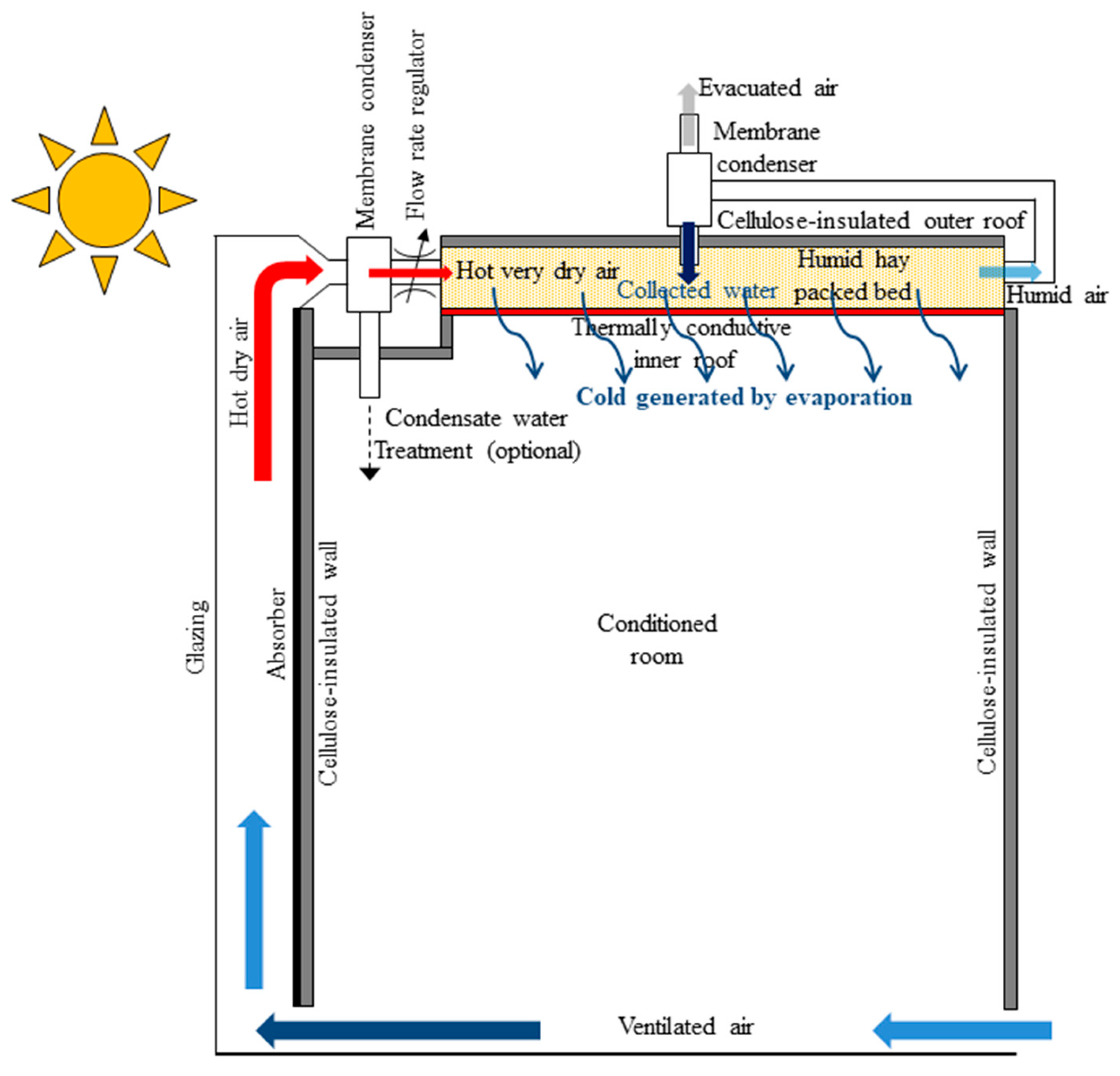
Figure 2.
Cooling effect of air flow rate and inlet air temperature on hay temperature.
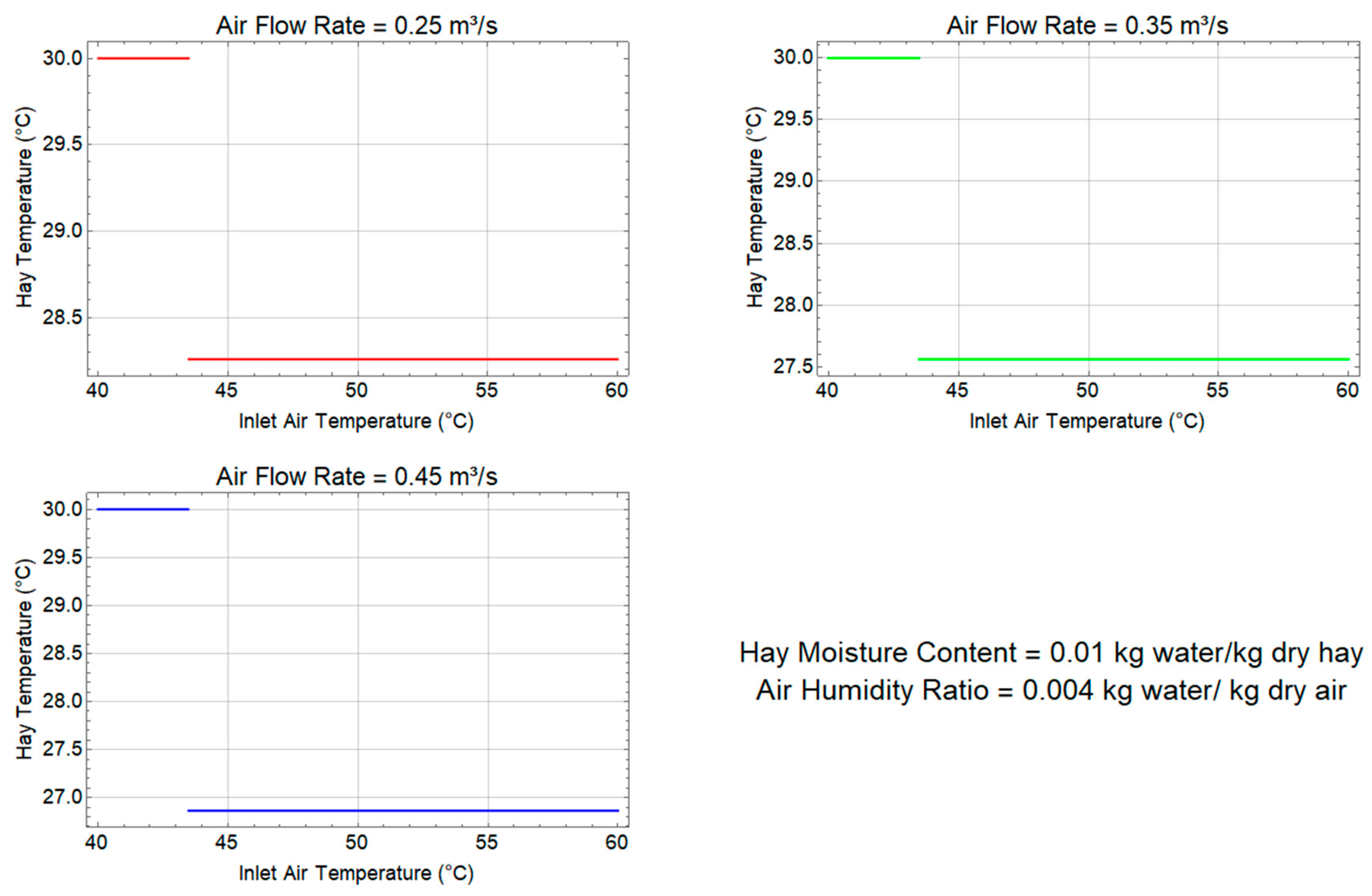
Figure 3.
Interplay of inlet air temperature and airflow rate on hay temperature.
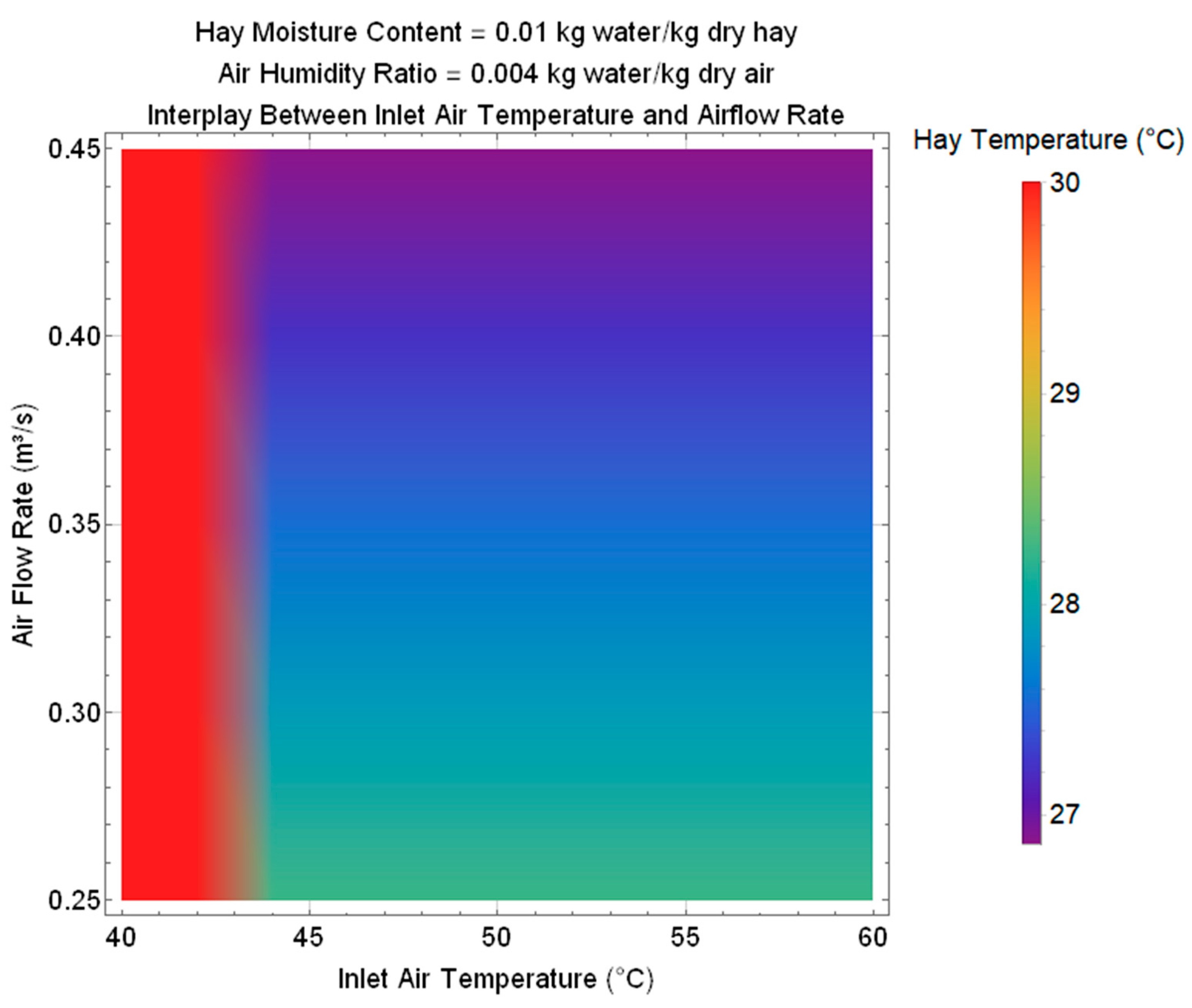
Figure 4.
Cooling effect of hay moisture content and inlet air temperature on hay temperature.
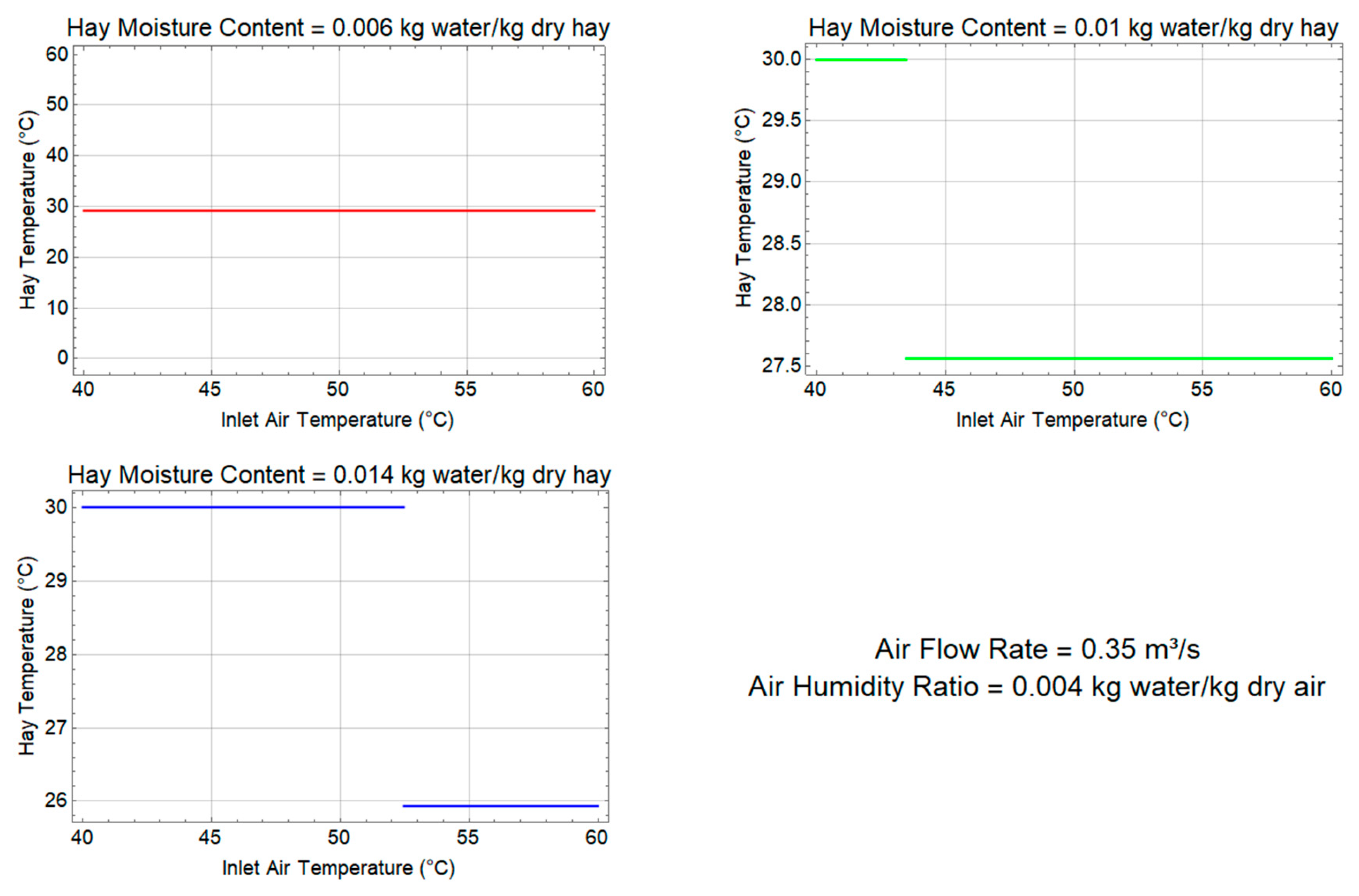
Figure 5.
Interplay of inlet air temperature and hay moisture content on hay temperature.
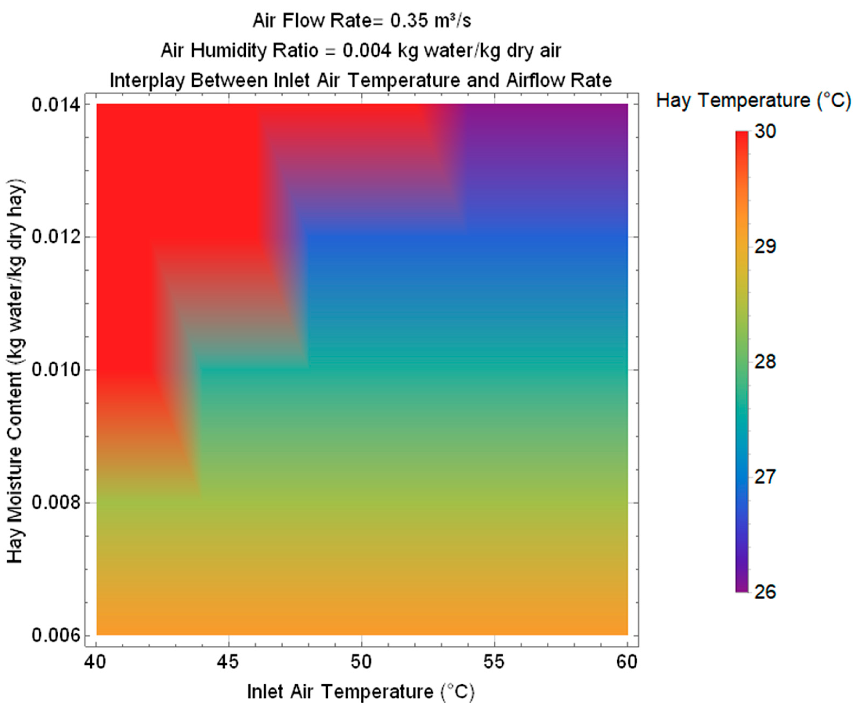
Figure 6.
Cooling effect of air humidity ratio and inlet air temperature on hay temperature.
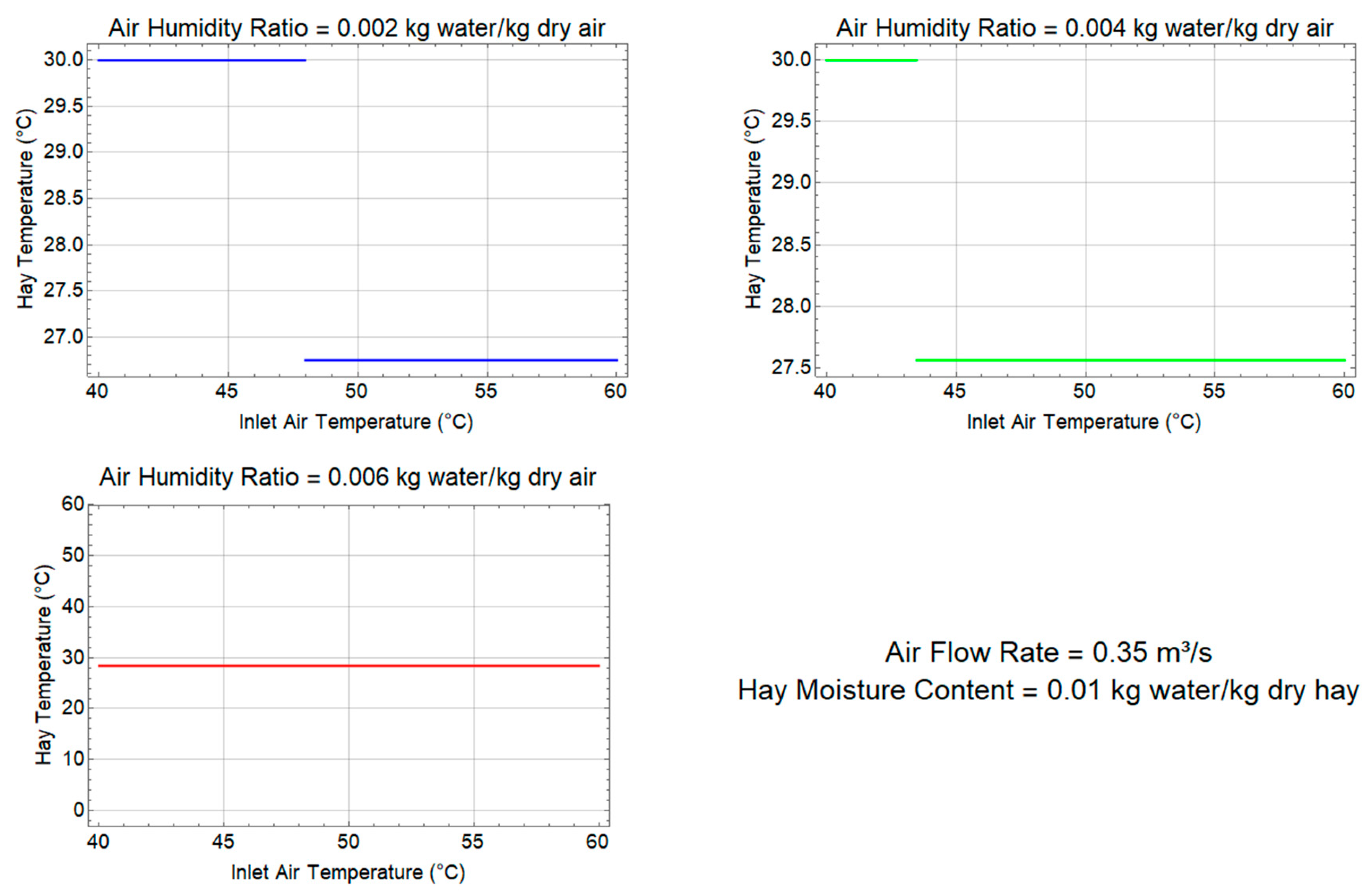
Figure 7.
Interplay of inlet air temperature and air humidity ratio on hay temperature.
Disclaimer/Publisher’s Note: The statements, opinions and data contained in all publications are solely those of the individual author(s) and contributor(s) and not of MDPI and/or the editor(s). MDPI and/or the editor(s) disclaim responsibility for any injury to people or property resulting from any ideas, methods, instructions or products referred to in the content. |
© 2025 by the authors. Licensee MDPI, Basel, Switzerland. This article is an open access article distributed under the terms and conditions of the Creative Commons Attribution (CC BY) license (http://creativecommons.org/licenses/by/4.0/).
Copyright: This open access article is published under a Creative Commons CC BY 4.0 license, which permit the free download, distribution, and reuse, provided that the author and preprint are cited in any reuse.


