
Submitted:
13 December 2024
Posted:
16 December 2024
You are already at the latest version
Abstract
The study investigates, by calculations, some ways to improve the thermal efficiency of plate heat exchangers used in the vegetable oil processing industry. The performance of these heat exchangers is limited by the heat transfer rate on the oil side and by the low thermal conductivity of the plate material. The study starts from a base case with vegetable oils cooled with water in plate heat exchangers, all with chevron angle 30o and different number of channels and plate transfer area. The change of one geometrical characteristic of the plates, namely the chevron angle, from 30o to 45o then to 60o, led to important increasing of the overall heat transfer coefficients, by 16.0 % when changing from 30o to 45o and by 28.1% on average when increasing the angle from 45o to 60o. This is an important increase accompanied by the rise of the pressure drops in circuits, but the values are acceptable since not exceeding 1 bar on oil circuit and 1.4 bar on cold fluid circuit, respectively. The use of Fe3O4–SiO2/Water hybrid nanofluids with concentration 0.5% v/v, 0,75% v/v and 1% v/v were investigated, to replace the cooling water. An increase by 2.2% on average was noticed when using the 1% v/v nanofluid comparatively with water, which is not large but adds to the chevron angle increasing. A supplementary 2.6% increase is possible by changing the manufacture material for plates with aluminum alloy 6060, also adding to the performances obtained by previous modifications. The total increase for all the set of modification can increase the performance by 34.2% on average. Thus, for the design of new PHEs, the miniaturization of the equipment becomes possible.
Keywords:
heat transfer
; plate heat exchanger
; chevron angle
; nanofluid
; aluminium alloy
1. Introduction
The plate heat exchangers (PHE) appeared one hundred years ago following the need for compact and more thermally efficient equipment for heat transfer [1]. Now they are widely used in chemical and food industry, among many other industrial applications [2]. The plate heat exchangers developed in a range of construction types: gasket plate-and-frame, brazed, welded, welded plate-and-shell [3]. Gasket plate-and-frame heat exchanger is the oldest type of this category but still popular for its benefits, such as versatility and easy maintenance [1,4], also known for its great thermal efficiency.
Over the years, the geometry of PHEs was improved to enhance the heat transfer. Practicing corrugations with chevron angles in plates was widely adopted to increase the heat transfer area per unit volume [5,6], to create supplementary turbulence or avoiding maldistribution of fluid in the ports [5,6]. Other small improvements were added, with effect on the thermal efficiency and roughness increasing. For example, wire inserts in the channels [7] led to increase of longitudinal turbulence with effect on the performance which enhanced by up to 38% comparing with conventional chevron type plates. Modifying the stainless steel of the plates by electrochemical etching with nitric acid-hydrochloric acid aqueous solution, under a voltage of 5 V, Nguyen et al. [8] obtained a rougher surface which had as an effect, the increase of heat transfer coefficient by 10.5-17.7%, but also increasing the friction coefficient by 21.3%.
Novel configurations of PHEs appeared, such as new geometry corrugates by repeating a basic half-ellipse cross-section [9] or the pillow-plate channels [10]. They bring some advantages. The repeated half-ellipse cross sections induce transverse disturbances in the fluid, with positive effect on the heat transfer up to 37% over the conventional PHEs [9]. The pillow-plate channel together with an elliptical welding spot in the middle of each unit improve the lateral mixing leading to superior thermal performances, and significantly decrease the pressure loss in the apparatus [10].
For three decades now, the use of nanofluids as cooling agents was extensively studied [11,12,13,14], aiming to exploit their superior thermal properties. Nanoparticles enhance the conductivity of conventional fluids. Mononanofluids contain a single type of nanoparticles such as metal, metallic oxides, graphene, etc. For example, carbon nanotubes (CNT) 1% vol enhance the thermal conductivity of ethylene glycol by 12.4% [15] and CeO2 dispersed at 0.75 % vol in water increased the overall heat coefficient by 28% [16]. Ajeeb et al. [12] reported for nanofluid with 0.2% vol Al2O3 in distilled water an increased heat transfer (Nu number) by 27%. Unavoidably, the pressure drops increases too, by 8%.
The hybrid particles synthetized together have a synergistic effect on the thermal conductivity and consequently on the heat transfer rate. For example, the aqueous nanofluid containing 1% vol hybrid particles Fe3O4-SiO2 with 47 nm dimension, increased the number of transfer units (NTU) by 24.51% and the thermal effectiveness by 13.23% [11]. There is a variety of hybrid particles discovered in the latest years (binary oxides, graphene composites with metals or metal-oxides, graphene-polymer composites, etc.) but some were tested on other types of heat exchangers, so need is to focus the thermal efficiency analysis on PHE applications and especially to calculate the overall heat transfer coefficients since they may vary with the geometrical characteristics’ dimensions of PHE [14].
To improve thermal-hydraulic performance, new materials for plates were developed: polymer-graphene composite [17], coatings with Ni, Cu, Ag [18], metallic microporous layers [19], some also responding to anticorrosion protection requirements.
The performance of PHEs, was not only tested in the laboratory but also, new equations describing their thermal efficiency were developed and validated [20,21,22]. These equations are required for sizing the industrial equipment.
Higher efficiency and miniaturization are the new challenges for the heat exchangers development. The overall heat transfer coefficients depend on the convection in fluids on both sides of the separating wall and also on the thermal conductivity of the wall’s material. These overall coefficients result lower than the lowest of the partial heat transfer coefficients. Any method to enhance the partial heat transfer coefficients is welcome.
Inspired by the works of forerunners, the present study investigates some solutions for the enhancement of heat transfer in gasket PHEs used in vegetable oil processing industry: modifying the chevron angle of corrugations, the use of Fe3O4-SiO2 nanoparticles suspended in the cooling water, and the change of the material for making the plates. The mathematical model of Dović and co-workers [22] validated and published by us previously for the calculation of heat transfer coefficients [23], together with accurate data for thermophysical properties of fluids, were used for the evaluation of the heat exchangers performances.
2. Materials and Methods/Research Method
2.1. Equipment
Three chevron plate heat exchangers, serving as coolers in different stages of vegetable oil processing, were tested with water in a previous work [23]. Their geometrical characteristics are the same (Figure 1), but differences appear in the effective heat transfer number of plates and the size of some elements (corrugation depth b, channel cross sectional flow area Ach) as seen in Table 1, so their total heat transfer areas are different.
2.2. The Research Design
2.2.1. The Base Case
The three PHEs have different technological functions. PHE #1 cools the raw vegetable oil (RO) from 85 oC to 42oC with cooling water (inlet temperature 30oC); PHE #2 cools the bleached oil (BO) from 60 oC to 45oC, and PHE#3 cools the winterized oil (WO) from 110 oC to 40oC. So, there are differences between their thermal load and in the fluids properties which vary with the origin and the temperature. However, the physical properties of raw, bleached and winterized oils are insignificantly different for those of the same vegetal origin.
There were two types of processing oil: sunflower and rapeseed, with density (ρ) and viscosity (μ) variation shown in Figure 2 and Figure 3. These values were determined in laboratory with an apparatus Anton Parr SVM 3000 which measure both density and viscosity on a preset range of temperature.
The specific heat capacity (cp) and thermal conductivity (λ) values for sunflower oil and rapeseed oil at working temperature were experimentally determined by Hoffmann et al. [24].
The experimental data were collected from three PHEs. In the first part of the experiment, the sunflower oil was processed at four different mass flow rates and in the second part, the rapeseed oil the PHEs ran at one mass flow rate all the campaign long. In total, 15 set of data are available in the base case for the calculations of thermal efficiency and pressure drop.

Table 2.
The base case primary data and calculated similarity criteria (Eq. 1-5 ) for cooling fluid: water and chevron angle β=30o.
Table 2.
The base case primary data and calculated similarity criteria (Eq. 1-5 ) for cooling fluid: water and chevron angle β=30o.
| Exp.# | PHE # | Oil circuit (hot fluid) | Water circuit (cold fluid) | ||||||
| Mass flowrate, kg/s | Resine | Nusine | Pr | Mass flowrate, kg/s | Resine | Nusine | Pr | ||
| 1 | 1 | 1.74 | 17 | 8.8 | 211.09 | 5.25 | 930 | 30.7 | 3.89 |
| 2 | 1 | 2.05 | 20 | 9.5 | 6.20 | 1073 | 34.1 | ||
| 3 | 1 | 2.46 | 24 | 10.4 | 7.43 | 1297 | 39.2 | ||
| 4 | 1 | 2.71 | 26 | 10.9 | 8.21 | 1437 | 42.2 | ||
| 5 | 2 | 1.94 | 11 | 11.6 | 287.5 | 2.55 | 584 | 21.5 | 3.89 |
| 6 | 2 | 2.19 | 13 | 12.2 | 2.88 | 658 | 23.4 | ||
| 7 | 2 | 2.49 | 15 | 12.9 | 3.27 | 748 | 25.7 | ||
| 8 | 2 | 2.78 | 15 | 12.9 | 3.62 | 828 | 27.7 | ||
| 9 | 3 | 1.77 | 9 | 5.8 | 151.0 | 6.02 | 600 | 21.5 | 3.68 |
| 10 | 3 | 1.48 | 10 | 6.2 | 7.11 | 707 | 24.2 | ||
| 11 | 3 | 1.83 | 12 | 6.7 | 8.52 | 845 | 27.5 | ||
| 12 | 3 | 1.95 | 14 | 7.0 | 9.41 | 936 | 29.6 | ||
| 13 | 1 | 2.72 | 18 | 8.4 | 202.15 | 8.23 | 1443 | 42.4 | 3.89 |
| 14 | 2 | 2.76 | 17 | 9.1 | 267.11 | 3.62 | 828 | 27.6 | 3.89 |
| 15 | 3 | 2.72 | 12 | 6.0 | 167.37 | 9.44 | 920 | 29.2 | 3.68 |
2.2.2. The Change of Corrugation Angles, Cooling and Material
Previous studies [25,26] have demonstrated that rising the corrugation angles of the plates causes changes in the flow pattern which led to the increase in heat transfer rate. These studies considered the heat exchange between hot water/ cold water (or nanofluid aqueous suspension) and the increase of heat transfer rate was impressive in this case. In our case, the hot fluid is vegetable oil with higher thermal resistance, so the heat transfer rate is expected to be lower. We investigated the rise of the corrugation/chevron angle from 30o to 45o and 60o, respectively, by observing the influence of the angle on the heat transfer coefficients and on the pressure drop in the heat exchangers.
The overall heat transfer coefficients In the studied heat exchangers are low due to the vegetable oil fluid partial coefficient, so a solution for increasing the heat transfer rate on the water side is to search for another fluid to replace the water. From the multitude of nanofluids experimented in literature, the majority are designed for refrigeration circuits; we chose an aqueous suspension of nanofluid, with better physical properties when working at fluid temperatures between 30-40 oC, the Fe3O4–SiO2/Water hybrid nanofluids. Since some of properties of nanofluids are frequently calculated using the laws for common mixtures [27,28], which can introduce big errors in case of hybrid materials suspensions, it is preferable to have all the physical propertied experimentally determined. In the article [29], density, viscosity, specific heat coefficient, thermal conductivity of Fe3O4–SiO2/Water hybrid nanofluids, varying with temperature, for solid content in suspension in range 0-1% volume concentration were determined experimentally. Then the partial heat transfer coefficients in the hot loop of the heat exchangers and the overall ones were compared between water and nanofluids with 0.5%, 0.75% and 1% vol. Fe3O4–SiO2. Also, the influence on the pressure drop in the apparatus was quantified as a function of the solid concentration in nanofluid.
Usually, the plates of PHEs are manufactured from stainless steel, a cheap and corrosion/erosion resistant material but with small thermal conductivity (cca.15 W/m K) compared with plain carbon steel (cca. 70 W/m K) at the working temperatures of the heat exchangers. It is desirable to find an affordable material with consistently higher conductivity to influence positively the heat transfer. The aluminum alloy 6060, with λ= 207 W/mK, possesses other attractive qualities: good processability and good weldability, making it prone for complex cross sections manufacture. The calculation of overall heat transfer coefficients was made for this material at the optimum case (corrugation angle, nanofluid) considered so far, and the coefficients were compared with those in case of stainless steel.
3. Model
An approach frequently found in literature for heat transfer efficiency [25,27], is to plot Nu vs. Re, where Nu and Re are Nusselt and Reynolds, respectively. According to Dović and co-authors’ model (Eq. 8), Nu and Re are redefined taking into consideration the cell’s sine duct as Nusine and Resine [22]. This model was validated in a previous work [23] and proved to be reliable.
Nusine numbers serve to calculate the partial heat transfer coefficients on each fluid side (Eq.1):
where L furr=b/sin(2β) is the furrow characteristic length, d,h,sine is the hydraulic diameter of the sine duct, and fapp is the apparent friction factor which takes into account the flow through sine duct. Fapp is calculated with Eq. 2:
B and C are constants depending on the channel geometry.
Eq. 3 and Eq. 4 serve the calculation of Resine number:
where usine is the the average velocity in the cell’s sine duct in furrow direction [m/s], υ is the kinematic viscosity [m2/s], is the mass flowrate in the channel [kg/s] and Ach,sine is the channel cross-section transverse to the furrow [m2].
After calculating Nusine for the cell sine duct, Nu number for the whole cell is calculated with Eq.5:
Hence, the partial heat transfer coefficients on hot circuit (hh) and on cold circuit (hc) respectively, are:
A more detailed presentation of this model is made in work [23].
Then the overall coefficient U is calculated with Eq.7:
where δ- plate thickness [m], and λ- metal thermal conductivity [W/m s].
For the calculation of the total pressure drop, one has to take into consideration the pressure drop in cells (Δpc) and the pressure drop in the ports (Δpr), summed up to give the total pressure drop (Δp). Since the cells work in parallel, the pressure drop in the cells equals the pressure drop in one cell. The equations 8-14 are used to calculate the pressure drop on both fluids sides.
where Gch is the mass flow in the channel (kg m-2s-1), μ – the fluid dynamic viscosity at the average temperature in the apparatus, μw – the viscosity at the wall, and Lef, Np , dh are geometrical characteristics (Table 1).
where Gp is the mass flow in the ports (kg m-2s-1); Δpr is negligible (units or dozens N/m2) in relation to Δpc, (bar), however it is common to take into consideration this term for the accuracy of the calculation.
The friction factor f is correlated with then the apparent friction factor fapp (Eq.2), by Eq.11.
3. Results and Discussion
3.1. Changing the Chevron Angle of Plates
The Nusine and Resine were calculated with Eq.1, respectively with Eq.3 on both fluid sides, for water as cooling fluid, at β=30o, then 45o and 60o. There were compared the results for the three chevron angles in a graph Nusine vs. Resine (Figure 4). Then, the partial heat transfer coefficients, h, were calculated with Eq.4-6 and plotted versus Resine (Figure 5).
Both plots indicate that the heat transfer rate increases with Resin confirming that turbulence favors the heat transfer. The variation is linear, with correlation coefficients r2 > 0.9. It is interesting that all values for a certain chevron angle are stringed on the same line whatever is the fluid, oil or water, knowing that they are fluids with very different physical properties. This could be explained by the influence of the plate geometry favoring the good mixing and uniformity of flow and temperature in the channel section.
The increasing of the heat transfer rate with chevron angle is important, by 14.8% average when passing from 30o to 45o, and 28.1% average when passing from 45o to 60o. This is an indication that building plates with larger chevron angle in the range 30o-60o may improve substantially the performance of the heat exchanger. Sadeghianjahromi and co-authors [25] demonstrated this by experiment, in the range 35o-50o- 65o, with the mention that the increase from 50 to 65o is much larger than the difference between 35o-50o, tendency confirmed by our data.
The overall heat transfer coefficients U were calculated with Eq.7 and the results are presented in Table 3.
The overall heat transfer coefficients are smaller than the partial coefficients in Eq.7, namely smaller than the smallest value between hc, and hr. Also, the differences when passing from angle 30o to 60o is smaller than that for the partial coefficients. However, an important increase of the overall heat transfer coefficients is noticed which can count for a better thermal performance of the apparatus.
The influence of the chevron angle on the pressure drop in the apparatus can be evaluated, at a first glance, by comparing the friction factors at 30o, 45o and 60o, both on water and oil circuits (Figure 6 a, b). The plot f vs. Resin shows that values of f on oil circuit are larger than those for water circuit. It is explained by Resin which is smaller for the laminar flow as it comes across the oil flow. According to Eq. 2 corroborated with Eq.11, the smaller Resine is, the bigger fapp is and, by consequence the the bigger f is. Both family curves respect the exponential trend with correlation coefficients 0.93-0.95 for oil and >0.90 for water. The friction coefficients for water are in the asymptotic zone of the exponential curve, this is why their variation appears linear. In Figure 6 a and b, it is obvious that increasing the chevron angle will lead to the rise of f values.
The calculated pressure drops also indicate the increase of the values with the corrugation angle, both on water and oil circuits, as seen in Figure 7 a and b. The pressure drops are larger on the water circuit than on the oil’s, even though the friction factors are smaller in water channels. This is due to the mass flow square much larger for the water circuit (see Eq.9).
For an apparatus keeping all geometrical characteristics except the corrugation angle, in the oil circuits, the pressure drops Δp increase by 133,2% on average when changing the angle from 30o to 45o, and by 462.6% from 30o to 60o. The figures are comparable for the water circuit, Δp increasing by 86.4% from 30o to 45o, and 414.3% from 30o to 60o, respectively. It is important to note that the pressure drop values are acceptable even for corrugation angle 60o, where the maximum values are below 1.0 bar for oil and below 1.4 bar for water. These data corroborated with the important gains in heat transfer rate when changing the chevron angle from 30o to 60o, suggest that this solution should be taken into consideration further.
3.2. Changing Water with Nanofluids as Cooling Medium
A nanofluid with good physical properties able to increase Pr numbers (=), should be preferred to improve the performance of PHEs. The Fe3O4–SiO2/Water hybrid nanofluids were selected from other aqueous suspensions since they have very good thermal conductivity, higher viscosity than water at working temperatures, even if the specific heat coefficient cp is slightly poorer. Pr numbers increased with concentration of solid in suspension, in our case, up to 16.9% for the suspension with 1% Fe3O4–SiO2. The concentration of these nanofluids is limited to 1% [29] due to the sharp increase of the viscosity over this concentration which can produce disturbances in the flow through the apparatus.
The partial heat transfer coefficients for the cold fluid hc were calculated, also were the overall coefficients for the PHEs with chevron angles 30o, 45o, 60o and fluids with 0.5%, 0.75% and 1% Fe3O4–SiO2 nanofluids (nf), then compared with water as cooling fluid. The results are summarized in Table 4, Table 5 and Table 6, for all 15 sets of data in the base case.
The results in Table 4, Table 5 and Table 6 show an important increase of partial heat transfer coefficients in the cooling circuit with the concentration of Fe3O4–SiO2 in the nanofluid: with up to 8.4% for the angle 30o, 22.8% for 45o, and 46,9% for 60o. However, the effect on the overall transfer coefficient is much smaller but not negligible: 2.2% for 30o, 2.3% for 45o and 2.1% for 60o, when increasing the concentration of Fe3O4–SiO2 from 0 to 1%. This adds to the increase of the overall coefficients obtained when increasing the chevron angle.
The effect of changing the water with Fe3O4–SiO2/Water hybrid nanofluids on the pressure drop is illustrated in Figure 8 a, b, c. As seen, the pressure drop in a PHE increases moderately with the concentration of Fe3O4–SiO2. By increasing the concentration from 0% to 1%, the pressure drops increases with 6.6% for the PHEs having chevron angles 30o, 4.7% for angle 45o and with 5.8% for 60o. The rise of the pressure drop because of the used nanofluid is much lower when compared with the increase because of changing the chevron angle and adds to that, without affecting it decisively.
3.3. Changing the Plate Material
When choosing the aluminum alloy 6060 for further calculations, the main reason was its very good thermal conductivity λ= 207 W/m K compared with the stainless steel (λ= 15 W/m K), the material from which are made the plates of PHEs. In addition, it is appropriate for the manufacture of the plates considering its good processability.
In previous calculations, the best overall heat transfer coefficients were obtained for plates with corrugation angle 60o and replacing the water as cooling fluid with 1% v/v Fe3O4–SiO2 nanofluid. The pressure drops in PHEs in the new conditions were acceptable, with values under 1.5 bar. So, the overall heat transfer coefficients were recalculated with Eq. 7, were only the λ plate was replaced. The results are presented in Table 5a.
Table 5.
The overall heat transfer coefficients for β=60o nanofluid 1%v/v and plate manufactured from alloy 6060 compared with the base case.
Table 5.
The overall heat transfer coefficients for β=60o nanofluid 1%v/v and plate manufactured from alloy 6060 compared with the base case.
| Data set # |
U [W/m K] β=30o fluid: water stainless steel plate Base case |
U [W/m K] β=60o nanofluid 1%, stainless steel plate |
U [W/m K] β=60o nanofluid 1% Alloy 6060 plate Final choice |
U increasing for changing the material β=60o nanofluid 1% |
U increasing from the base case to final choice % |
|---|---|---|---|---|---|
| 1 | 544 | 843 | 860 | 2.0 | 58.1 |
| 2 | 606 | 908 | 929 | 2.3 | 53.2 |
| 3 | 681 | 996 | 1022 | 2.6 | 50.0 |
| 4 | 729 | 1041 | 1070 | 2.7 | 46.7 |
| 5 | 525 | 630 | 644 | 2.3 | 22.7 |
| 6 | 622 | 684 | 701 | 2.5 | 12.7 |
| 7 | 613 | 706 | 724 | 2.6 | 18.1 |
| 8 | 645 | 745 | 765 | 2.7 | 18.7 |
| 9 | 409 | 511 | 519 | 1.5 | 26.8 |
| 10 | 447 | 549 | 558 | 1.7 | 24.9 |
| 11 | 502 | 596 | 607 | 1.9 | 20.9 |
| 12 | 533 | 631 | 644 | 2.0 | 20.7 |
| 13 | 767 | 1077 | 1121 | 4.1 | 46.1 |
| 14 | 820 | 1220 | 1275 | 4.5 | 55.5 |
| 15 | 598 | 800 | 824 | 3.0 | 37.7 |
| Average increase: | 2.6% | 34.2% | |||
The average increase of U only by changing the material is 2.6%. As calculations went, by adopting the chevron angle β=60o, the hybrid nanofluid Al2O3-SiO2 with 1% v/v concentration and the aluminum alloy 6060 as manufacture material, the overall heat transfer coefficients increase by 12.7-58.1% for each PHE, with an average of 34.2%. This is an important increasing, considering the resistance that the vegetable oil imposes to the heat transfer rate.
4. Conclusion
Looking for solutions with the aim to improve the heat transfer in PHEs used in the vegetable oil processing industry, the following ways were searched: changing the corrugation inclination angle relative to vertical direction, replacing the water as cooling medium with appropriate nanofluid and replacing the material for plate manufacture with an alloy with better thermal conductivity.
The findings of our study are the following:
The biggest influence on the PHEs performances was when increasing the corrugation angle from β=30o to β=45o, then to β=60o. Since the rise of partial heat transfer coefficients hc was spectacular, the overall coefficients (U) increased less but this was an important rise, by 16.0 % when changing from 30o to 45o and by 28.1% from 45o to 60o. When increasing the corrugation angle from β=30o to β=60o, the pressure drops increase by 462.6% on average in the oil circuit and by 414.3% on average in the cooling fluid circuit. The values of pressure drops are acceptable on both fluids sides since not exceeding 1 bar in oil and 1.4 bar in cold fluid circuit, respectively.
The use of Al2O3-SiO2/Water hybrid nanofluid as cooling medium also improves the thermal efficiency of the PHEs by 2.2% on average, also increasing with the concentration of solid in fluid, but this is limited to 1% v/v because of the sharp increase of the fluid viscosity over this concentration.
Changing the manufacture material for plates with aluminum alloy improves the heat transfer coefficients by 2.6 % on average and the total increase for all the set of modification can increase the performance by 34.2% on average. For the design of new PHEs, the miniaturization of the equipment becomes possible.
Author Contributions
Conceptualization, methodology, software, validation, investigation, A.-A.N. and C.I.K.; project administration, data curation and writing-original draft preparation, A.-A.N.; supervision, writing-review and editing, C.I.K. All authors have read and agreed to the published version of the manuscript.
Funding
This research received no external funding
Data Availability Statement
Primary data were obtained from our original experiment. All processed data are included in this article and are available for further processing and interpretation by other authors.
Conflicts of Interest
The authors declare no conflicts of interest.
References
- Yang, J.; Jacobi, A.; Liu, W. Heat transfer correlations for single-phase flow in plate heat exchangers based on experimental data. App.Therm. Eng. 2017, 113, 1547–1557. [Google Scholar] [CrossRef]
- Hedayati, S.; Ansarifar, E.; Jafari, M.S. Thermal processing of food products by steam and hot water, Elsevier: Cambridge, UK, 2023, p.111-128.
- Arsenyeva, O.; Tovazhnyanskyy, L.; Kapustenko, P.; Klemeš, J.J.; Varbanov, P.S. Review of Developments in Plate Heat Exchanger Heat Transfer Enhancement for Single-Phase Applications in Process Industries. Energies 2023, 16, 4976. [Google Scholar] [CrossRef]
- Kumar, S.; Kumar Singh, S.; Sharma, D. Comprehensive Review on Thermal Performance Enhancement of Plate Heat Exchanger. Int. J. Thermophys. 2022, 43, 109. [Google Scholar] [CrossRef]
- Sri Valli, G.; Kommineni, R.; Sreedhara Rao, B. A Literature Review on Corrugated Plate Heat Exchanger. Mater. Today. 2019, 18, 320–326. [Google Scholar] [CrossRef]
- Elmaaty, T.M.A.; Kabeel, A.E.; Mahgoub, M. Corrugated plate heat exchanger review. Renew. Sust. Energ. Rev. 2017, 70, 852–860. [Google Scholar] [CrossRef]
- Nitesh, K.; Panday, Shailendra, N. Singh. Study of thermo-hydraulic performance of chevron type plate heat exchanger with wire inserts in the channel. Int. J. Therm. Sci. 2021, 173, 107360. [Google Scholar] [CrossRef]
- Nguyen, D.H.; Kim, K.M.; Shim, G.H.; Kim, J.H.; Lee, Ch.H.; Lim, S.T.; Ahn, S.H. Experimental study on the thermal-hydraulic performance of modified chevron plate heat exchanger by electrochemical etching method. Int. J. Heat Mass Transf. 2020, 155, 119857. [Google Scholar] [CrossRef]
- Khail, A.A.; Erișen, A. Heat transfer and performance enhancement investigation of novel plate heat exchanger. TSEP 2022, 34, 101368. [Google Scholar] [CrossRef]
- Piper, M.; Zibart, A.; Kenig, E.Y. Design equations for turbulent forced convection heat transfer and pressure loss in pillow-plate channels. Int. J. Therm. Sci. 2017, 120, 459–468. [Google Scholar] [CrossRef]
- Syam Sundar, L.; Chandra Mouli, K.V.V. Effectiveness and number of transfer units of plate heat exchanger with Fe3O4–SiO2/Water hybrid nanofluids: Experimental and artificial neural network predictions. Case Stud. Therm. Eng. 2024, 53, 103949. [Google Scholar] [CrossRef]
- Ajeeb, W.; Thieleke da Silva, R.R.S.; Sohel Murshed, S.M. Experimental investigation of heat transfer performance of Al2O3 nanofluids in a compact plate heat exchanger. Appl.Therm. Eng. 2023, 218, 119321. [Google Scholar] [CrossRef]
- Chen, T.; Kim, J.; Cho, H. Theoretical analysis of the thermal performance of a plate heat exchanger at various chevron angles using lithium bromide solution with nanofluid. IJR 2014, 48, 233–244. [Google Scholar] [CrossRef]
- Syam Sundar, L. Synthesis and characterization of hybrid nanofluids and their usage in different heat exchangers for improved heat transfer rates: A critical review. JESTEC 2023, 44, 101468. [Google Scholar] [CrossRef]
- Liu, M.-S.; Lin, M.-C.-C.; Huang, I.-T.; Wang, C.-C. Enhancement of thermal conductivity with carbon nanotube for nanofluids. Int. Comm. Heat Mass Transf. 2005, 32, 1202–1210. [Google Scholar] [CrossRef]
- Tiwari, A.K.; Ghosh, P.; Sarkar, J. Heat transfer and pressure drop characteristics of CeO2/water nanofluid in plate heat exchanger. Appl. Therm. Eng. 2013, 57, 24–32. [Google Scholar] [CrossRef]
- Kiepfer, H.; Stannek, P.; Grundler, M.; Bart, H.-J. Development and thermal performance of a thermoplastic-graphite-composite based plate heat exchanger for use in corrosive media. App. Therm. Eng. 2024, 236, 121581. [Google Scholar] [CrossRef]
- Nguyen, D.H.; Kim, K.M.; Nguyen Vo, T.T.; Shim, G.H.; Kim, J.H.; Ahn, H.S. Improvement of thermal-hydraulic performance of plate heat exchanger by electroless nickel, copper and silver plating. Case Stud. Therm. Eng. 2021, 23, 100797. [Google Scholar] [CrossRef]
- Wajs, J.; Mikielewicz, D. Influence of metallic porous microlayer on pressure drop and heat transfer of stainless steel plate heat exchanger. Appl. Therm. Eng. 2016, 93, 1337–1346. [Google Scholar] [CrossRef]
- Arsenyeva, O.; Tovazhnyansky, L.; Kapustenko, P.; Khavin, G. Mathematical Modelling and Optimal Design of Plate-and-Frame Heat Exchangers. Chem. Eng. Trans. 2009, 18, 791–796. [Google Scholar]
- Martin, H. A theoretical approach to predict the performance of chevron-type plate heat exchangers. Chem. Eng. Process Process. Intensif. 1996, 35, 301–310. [Google Scholar] [CrossRef]
- Dović, D.; Palm, B.; Švaić, S. Generalized correlations for predicting heat transfer and pressure drop in plate heat exchanger channels of arbitrary geometry. Int. J. Heat Mass Transf. 2009, 52, 4553–4563. [Google Scholar] [CrossRef]
- Neagu, A.A.; Koncsag, C.I. Model Validation for the Heat Transfer in Gasket Plate Heat Exchangers Working with Vegetable Oils. Processes. 2022, 10, 102. [Google Scholar] [CrossRef]
- Hoffmann, J.-F.; Vaitilingom, G.; Henry, J.-F.; Chirtoc, M.; Olives, R.; Goetz, V.; Py, X. Temperature dependence of thermophysical and rheological properties of seven vegetable oils in view of their use as heat transfer fluids in concentrated solar plants. Sol. Energy Mater. Sol. Cells. 2018, 178, 129–138. [Google Scholar] [CrossRef]
- Sadeghianjahromi, A.; Jafari, A.; Wang, Chi-Chuan. Numerical investigation of the effect of chevron angle on thermofluids characteristics of non-mixed and mixed brazed plate heat exchangers with experimental validation. Int. J. Heat Mass Transf. 2022, 184, 122278. [Google Scholar] [CrossRef]
- Kumar Tiwari, A.; Said, Z.; Pandya, N.S. , Shah, H. Effect of plate spacing and inclination angle over the thermal performance of plate heat exchanger working with novel stabilized polar solvent-based silicon carbide nanofluid. J. Energy Storage. 2023, 60, 106615. [Google Scholar] [CrossRef]
- Khan, A.A.; Danish, M.; Rubaiee, S.; Yahya, S.M. Insight into the investigation of Fe3O4/SiO2 nanoparticles suspended aqueous nanofluids in hybrid photovoltaic/thermal system. CLCE, 2022, 11, 100572. [Google Scholar] [CrossRef]
- Syam Sundar, L.; Chandra Moulib, K.V.V.; Effectiveness and number of transfer units of plate heat exchanger.
- with Fe3O4–SiO2/Water hybrid nanofluids: Experimental and artificial neural network predictions. Case Studies Therm. Eng. 2024, 53, 103949. [CrossRef]
- Alklaibi, A.M.; Chandra Mouli, K.V.V.; Syam Sundar, L. Heat transfer, and friction factor of Fe3O4–SiO2/Water hybrid nanofluids in a plate heat exchanger: Experimental and ANN predictions. Int.J.Therm.Sci. 2024, 195, 108608. [Google Scholar] [CrossRef]
Figure 1.
Chevron corrugated plate and its main characteristics.
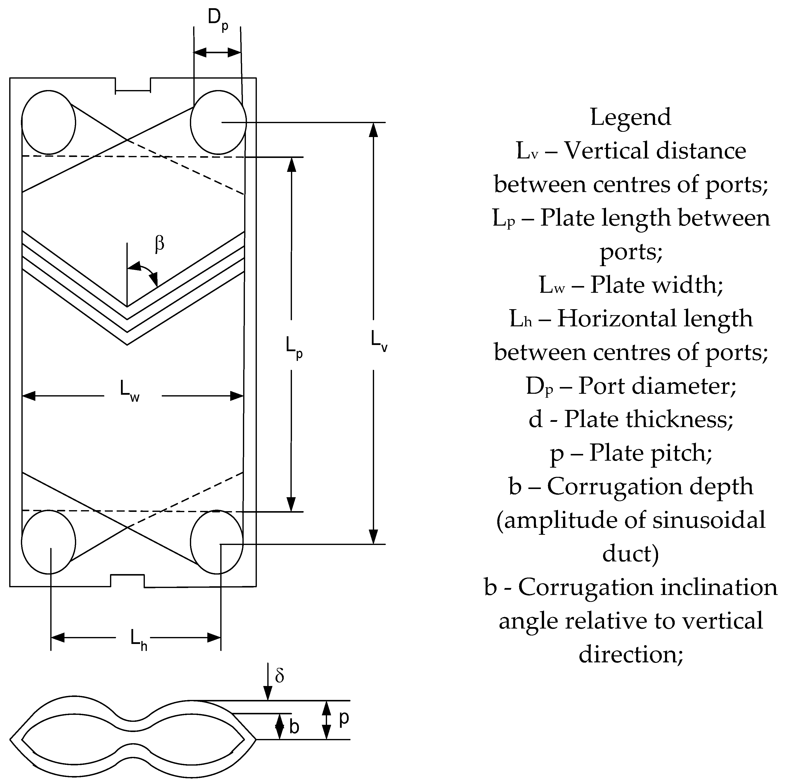
Figure 2.
Variation of oils’ density with temperature.
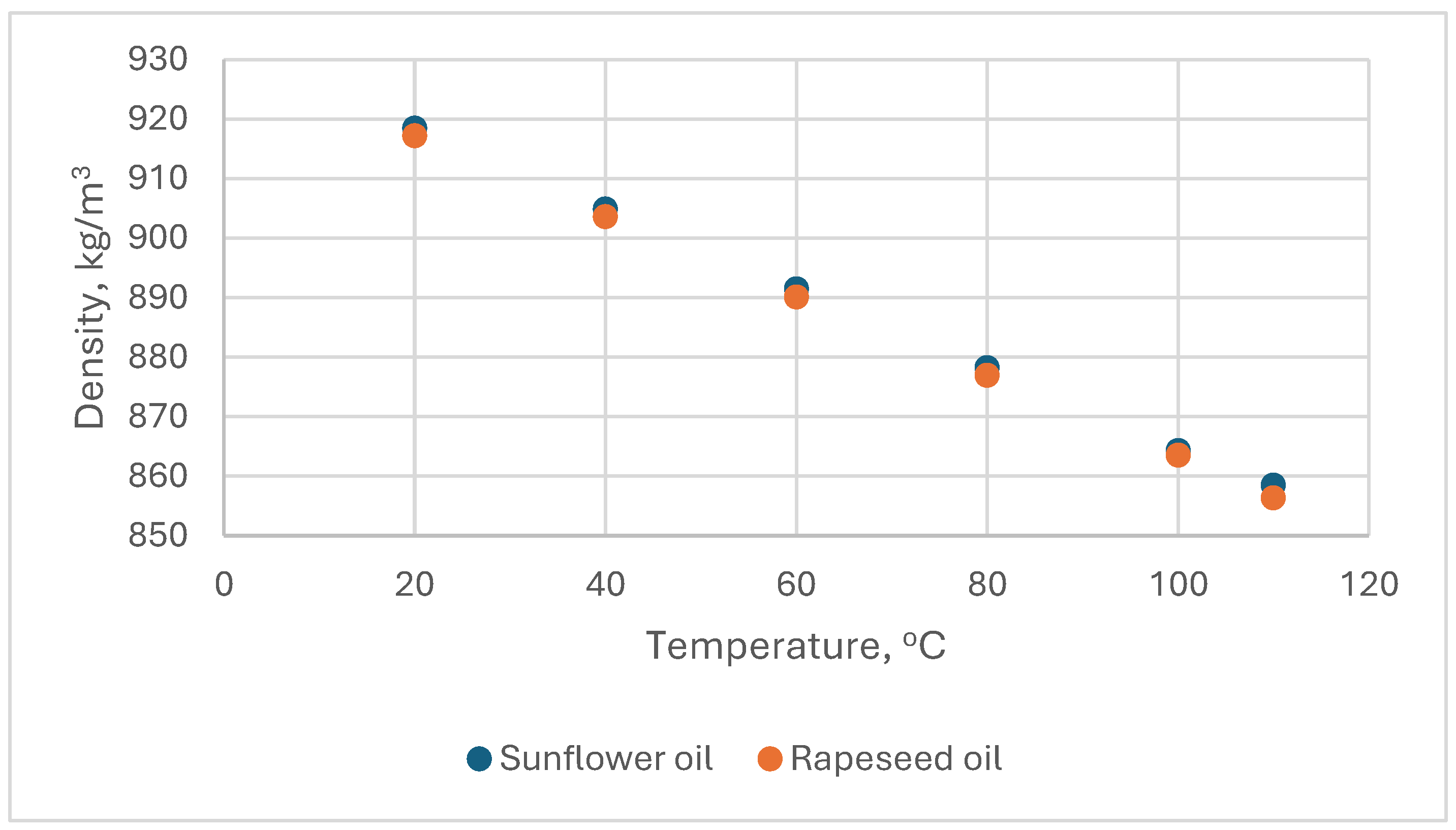
Figure 3.
Variation of oils’ dynamic viscosity with temperature.
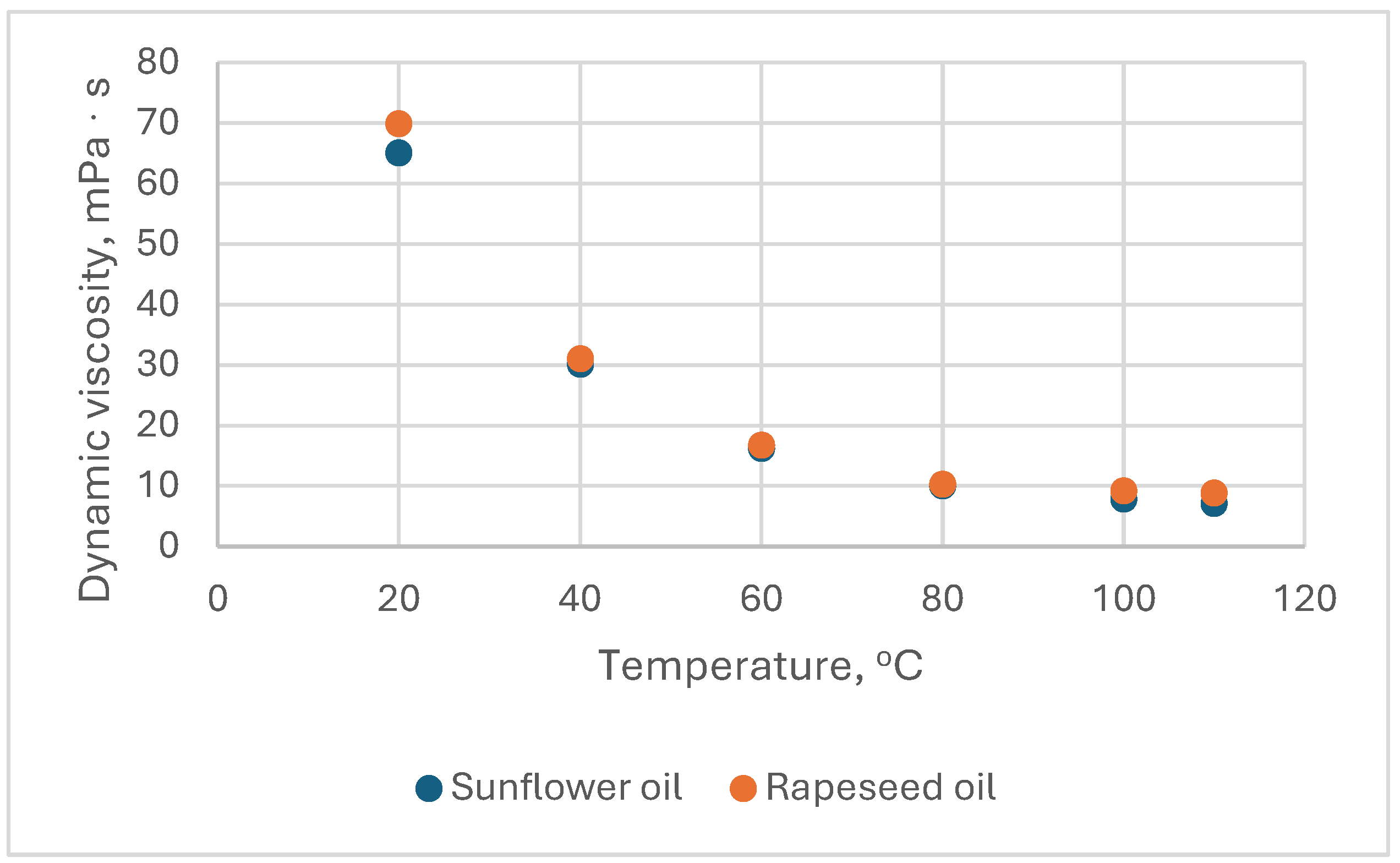
Figure 4.
Nusine vs. Resine in the fluid circuits of PHEs with corrugation inclination angle relative to vertical direction β= 30o, 45o and 60o.
Figure 4.
Nusine vs. Resine in the fluid circuits of PHEs with corrugation inclination angle relative to vertical direction β= 30o, 45o and 60o.
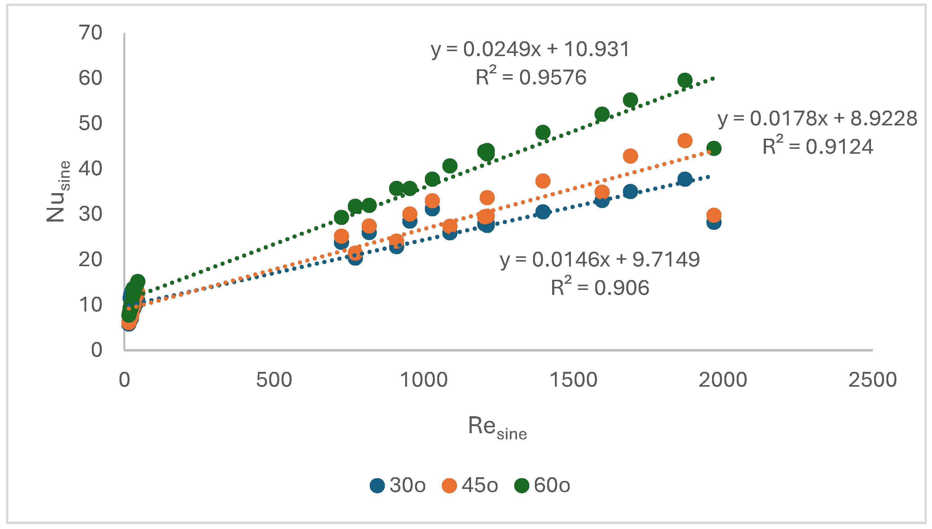
Figure 5.
Partial heat transfer coefficients in PHEs with corrugation inclination angle relative to vertical direction β= 30o, 45o and 60o.
Figure 5.
Partial heat transfer coefficients in PHEs with corrugation inclination angle relative to vertical direction β= 30o, 45o and 60o.
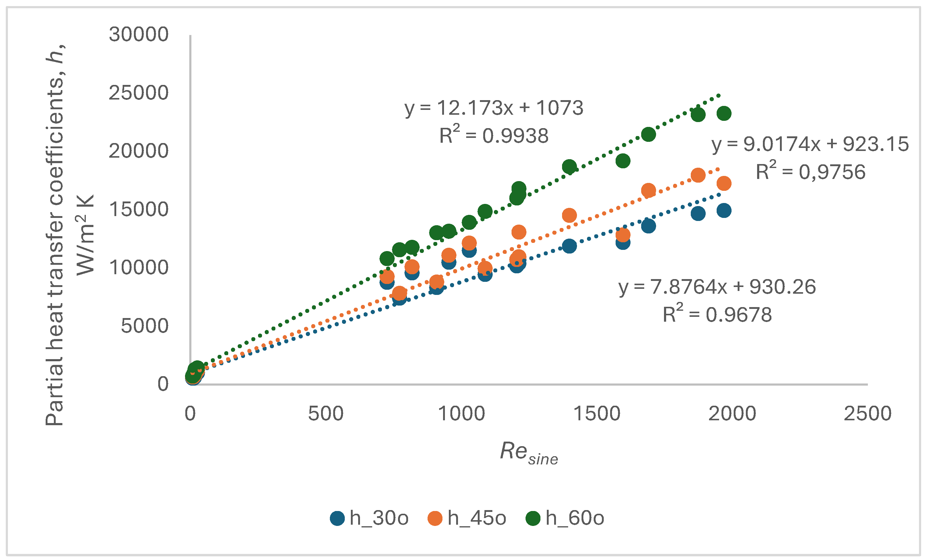
Figure 6.
The variation of friction factor in the oil circuit (a) and in the water circuit (b) of the PHEs.
Figure 6.
The variation of friction factor in the oil circuit (a) and in the water circuit (b) of the PHEs.
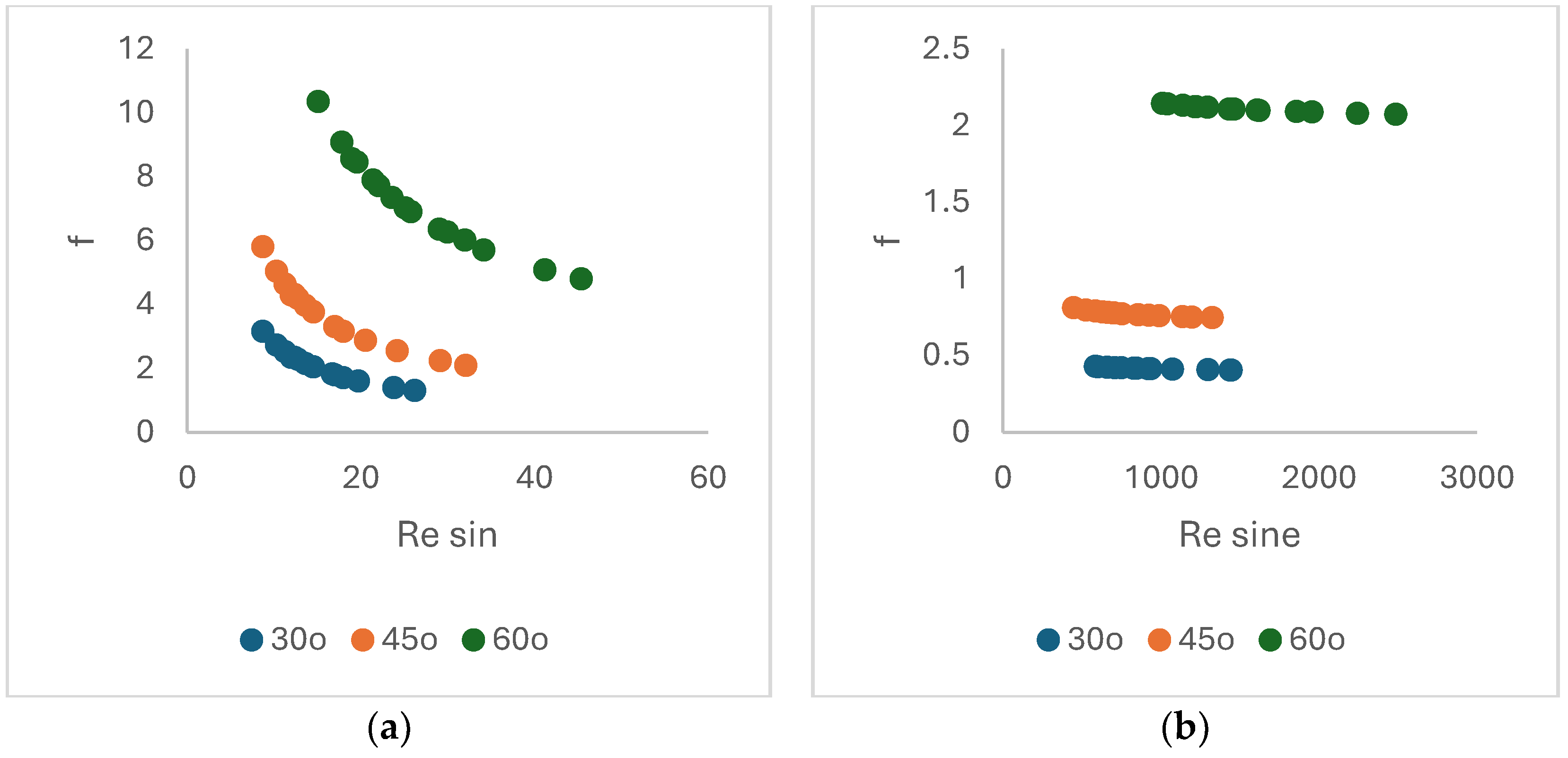
Figure 7.
The variation of pressure drops in the oil circuit (a) and in the water circuit (b) of the PHEs.
Figure 7.
The variation of pressure drops in the oil circuit (a) and in the water circuit (b) of the PHEs.
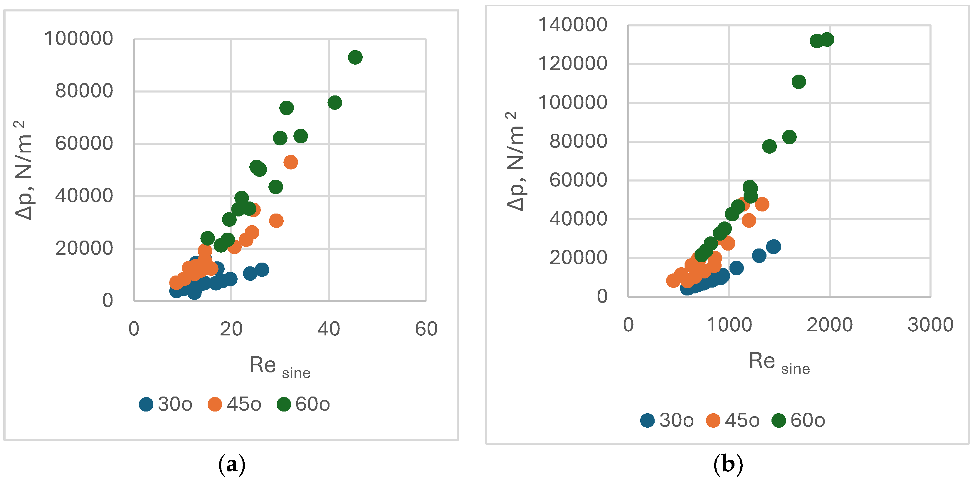
Figure 8.
The variation of pressure drops in the on the water circuit comparatively with nanofluids for PHEs with chevron angles 30o (a), 45o and 60o.
Figure 8.
The variation of pressure drops in the on the water circuit comparatively with nanofluids for PHEs with chevron angles 30o (a), 45o and 60o.
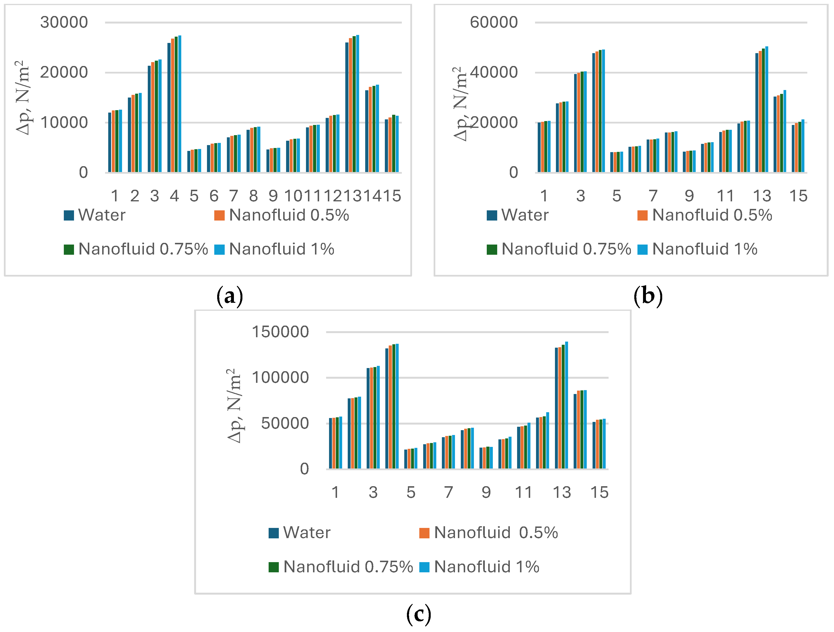
Table 1.
The size of geometrical characteristics of the PHEs.
| Geometrical Characteristics of Chevron Plates | Symbol | Heat Exchanger #1 | Heat Exchanger #2 | Heat Exchanger #3 |
|---|---|---|---|---|
| Vertical distance between centres of ports | Lv | 1070 (mm | 1070 (mm) | 1070 (mm) |
| Plate length between ports (effective length) | Lp (Leff) | 858 (mm) | 858 (mm) | 858 (mm) |
| Plate width | Lw | 450 (mm) | 450 (mm) | 450 (mm) |
| Horizontal length between centres of ports | Lh | 238 (mm) | 238 (mm) | 238 (mm) |
| Port diameter | Dp | 212 (mm) | 212 (mm) | 212 (mm) |
| Plate thickness | δ | 0.6 (mm) | 0.6 (mm) | 0.6 (mm) |
| Plate pitch | p | 3.17 (mm) | 3.14 (mm) | 3.14 (mm) |
| Corrugation depth (amplitude of sinusoidal duct) | b | 2.57 (mm) | 2.54 (mm) | 2.55 (mm) |
| Corrugation inclination angle relative to vertical direction | β | 30° | 30° | 30° |
| Hydraulic diameter (=2 b/φ) | dh | 4.396 (mm) | 4.34 (mm) | 4.5 (mm) |
| Channel cross-sectional free flow area | Ach | 1.116 × 10⁻³ (m2) | .144 × 10−3 (m2) | 1.145 × 10⁻³ (m2) |
| Heat transfer total area | Ae | 11.2 (m2) | 9.2 (m2) | 19.7 (m2) |
| Total number of plates | Nt | 35 | 28 | 63 |
| Number of fluid passes | Np | 1 | 1 | 1 |
| Number of channels for one pass | Ncp | 17 | 13.5 | 31 |
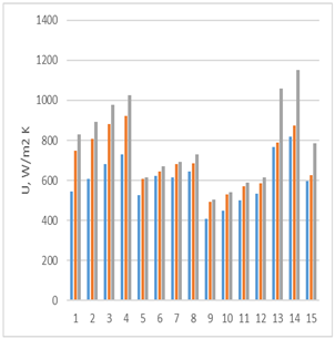
Table 3.
The increase of overall heat transfer coefficients U with increasing the chevron angle *.
| Data set # | U30o | U45o | U60o |
(%) 30-45 |
(%) 45-60 |
 |
| 1 | 544 | 747 | 828 | 37.3 | 52.1 | |
| 2 | 606 | 807 | 894 | 33.1 | 47.4 | |
| 3 | 681 | 881 | 979 | 29.2 | 43.6 | |
| 4 | 729 | 922 | 1027 | 26.4 | 40.9 | |
| 5 | 525 | 609 | 615 | 16,1 | 17.1 | |
| 6 | 622 | 643 | 669 | 3.5 | 7.6 | |
| 7 | 613 | 681 | 691 | 11.1 | 12.7 | |
| 8 | 645 | 686 | 729 | 6.4 | 13.0 | |
| 9 | 409 | 492 | 505 | 20.3 | 23.4 | |
| 10 | 447 | 529 | 542 | 18.3 | 21.3 | |
| 11 | 502 | 571 | 588 | 13.8 | 17.0 | |
| 12 | 533 | 587 | 614 | 10.2 | 15.2 | |
| 13 | 767 | 787 | 1059 | 2.7 | 3.0 | |
| 14 | 820 | 872 | 1152 | 6.4 | 40.4 | |
| 15 | 598 | 626 | 786 | 4.7 | 3.5 | |
| Average increase, % | 16.0 | 28.1 | ||||
*Legend:  chevron angle 30o
  chevron angle 45o
  chevron angle 60o .
chevron angle 30o chevron angle 45o chevron angle 60o .
Table 4.
Partial hc and overall heat transfer coefficients U for chevon angle 30o on water circuit comparatively with nanofluids [W/m2K].
Table 4.
Partial hc and overall heat transfer coefficients U for chevon angle 30o on water circuit comparatively with nanofluids [W/m2K].
| Data set # | hc water | hc 0.5%nf. |
Hc 0.75% nf. |
Hc 1% nf. |
U water |
U 0.5% nf. |
U 0.75% nf. |
U 1% nf. |
|---|---|---|---|---|---|---|---|---|
| 1 | 10358 | 11010 | 11451 | 11425 | 544 | 545 | 547 | 549 |
| 2 | 11550 | 12391 | 12498 | 12665 | 606 | 608 | 609 | 613 |
| 3 | 13538 | 14100 | 14005 | 14525 | 681 | 682 | 683 | 684 |
| 4 | 14420 | 15171 | 15396 | 15650 | 729 | 731 | 733 | 755 |
| 5 | 7424 | 7768 | 7877 | 7973 | 525 | 530 | 533 | 555 |
| 6 | 8099 | 8461 | 8516 | 8690 | 622 | 623 | 625 | 630 |
| 7 | 8858 | 9275 | 9399 | 9506 | 613 | 630 | 632 | 644 |
| 8 | 9546 | 9985 | 10007 | 10216 | 645 | 646 | 646 | 649 |
| 9 | 7058 | 7457 | 7536 | 7609 | 409 | 411 | 414 | 417 |
| 10 | 7676 | 8470 | 8180 | 8379 | 447 | 448 | 449 | 451 |
| 11 | 8439 | 8756 | 8814 | 9517 | 502 | 503 | 504 | 507 |
| 12 | 9243 | 9788 | 9926 | 10128 | 533 | 534 | 536 | 539 |
| 13 | 10181 | 10281 | 10399 | 10860 | 767 | 781 | 783 | 785 |
| 14 | 10495 | 10646 | 10788 | 11211 | 820 | 828 | 841 | 855 |
| 15 | 10925 | 11032 | 11261 | 11832 | 598 | 612 | 616 | 615 |
Table 5.
Partial hc and overall heat transfer coefficients U for chevon angle 45o on water circuit comparatively with nanofluids [W/m2K].
Table 5.
Partial hc and overall heat transfer coefficients U for chevon angle 45o on water circuit comparatively with nanofluids [W/m2K].
| Data set # | hc water | hc 0.5%nf. |
Hc 0.75% nf. |
Hc 1% nf. |
U water |
U 0.5% nf. |
U 0.75% nf. |
U 1% nf. |
|---|---|---|---|---|---|---|---|---|
| 1 | 10850 | 12207 | 12432 | 13190 | 747 | 753 | 754 | 767 |
| 2 | 12038 | 13772 | 14023 | 14875 | 807 | 815 | 816 | 826 |
| 3 | 13821 | 15725 | 16009 | 16979 | 881 | 890 | 891 | 902 |
| 4 | 14899 | 16910 | 17214 | 18254 | 992 | 1003 | 1005 | 1018 |
| 5 | 8101 | 8577 | 8827 | 9264 | 609 | 616 | 616 | 624 |
| 6 | 8835 | 9361 | 9632 | 10106 | 643 | 650 | 651 | 660 |
| 7 | 9694 | 10254 | 10549 | 11066 | 681 | 689 | 690 | 698 |
| 8 | 10624 | 11030 | 11346 | 11899 | 686 | 695 | 695 | 702 |
| 9 | 7245 | 8979 | 9059 | 9570 | 492 | 497 | 497 | 502 |
| 10 | 8135 | 10110 | 10197 | 10769 | 529 | 535 | 536 | 542 |
| 11 | 9241 | 11523 | 11619 | 12267 | 571 | 577 | 577 | 586 |
| 12 | 9945 | 12379 | 12481 | 13175 | 587 | 594 | 595 | 601 |
| 13 | 11240 | 11951 | 12944 | 13617 | 787 | 795 | 796 | 802 |
| 14 | 11042 | 12240 | 12350 | 12621 | 872 | 877 | 879 | 887 |
| 15 | 9722 | 9864 | 9993 | 12798 | 626 | 631 | 631 | 637 |
Table 6.
Partial hc and overall heat transfer coefficients U for chevon angle 60o on water circuit comparatively with nanofluids [W/m2K].
Table 6.
Partial hc and overall heat transfer coefficients U for chevon angle 60o on water circuit comparatively with nanofluids [W/m2K].
| Data set # | hc water | hc 0.5%nf. |
Hc 0.75% nf. |
Hc 1% nf. |
U water |
U 0.5% nf. |
U 0.75% nf. |
U 1% nf. |
|---|---|---|---|---|---|---|---|---|
| 1 | 12085 | 16249 | 17077 | 17493 | 828 | 839 | 840 | 843 |
| 2 | 13629 | 18322 | 18975 | 19757 | 894 | 904 | 906 | 908 |
| 3 | 15558 | 20946 | 21823 | 22583 | 979 | 993 | 994 | 996 |
| 4 | 16728 | 22557 | 23546 | 24297 | 1027 | 1036 | 1038 | 1041 |
| 5 | 8361 | 11230 | 11718 | 12231 | 616 | 627 | 628 | 630 |
| 6 | 9122 | 12271 | 12786 | 13346 | 669 | 681 | 682 | 684 |
| 7 | 9990 | 13458 | 14039 | 14638 | 691 | 702 | 704 | 706 |
| 8 | 10743 | 14488 | 15131 | 15758 | 729 | 742 | 743 | 745 |
| 9 | 8843 | 11793 | 12579 | 13066 | 505 | 508 | 510 | 511 |
| 10 | 9952 | 13299 | 14186 | 14727 | 542 | 547 | 548 | 549 |
| 11 | 11338 | 15180 | 16194 | 16786 | 588 | 593 | 594 | 596 |
| 12 | 12178 | 16320 | 17411 | 18098 | 614 | 628 | 629 | 631 |
| 13 | 14785 | 16918 | 22601 | 23249 | 1059 | 1073 | 1075 | 1077 |
| 14 | 12773 | 15932 | 18571 | 19285 | 1152 | 1172 | 1176 | 1220 |
| 15 | 12124 | 15248 | 16358 | 16658 | 786 | 796 | 798 | 800 |
Disclaimer/Publisher’s Note: The statements, opinions and data contained in all publications are solely those of the individual author(s) and contributor(s) and not of MDPI and/or the editor(s). MDPI and/or the editor(s) disclaim responsibility for any injury to people or property resulting from any ideas, methods, instructions or products referred to in the content. |
© 2024 by the authors. Licensee MDPI, Basel, Switzerland. This article is an open access article distributed under the terms and conditions of the Creative Commons Attribution (CC BY) license (http://creativecommons.org/licenses/by/4.0/).
Copyright: This open access article is published under a Creative Commons CC BY 4.0 license, which permit the free download, distribution, and reuse, provided that the author and preprint are cited in any reuse.


