
Submitted:
02 December 2025
Posted:
04 December 2025
You are already at the latest version
Abstract
In this study, a straightforward strategy for the preparation of functional carbon-based materials for hydrazine oxidation (HzOR) is presented. A highly efficient, cost-effective iron (Fe) and manganese-iron (MnFe) supported nitrogen-doped carbon (N-C) material was developed using a hydrothermal synthesis method. Meanwhile, N-C material was obtained from biomass – birch-wood chips – using hydrothermal carbonisation (HTC), followed by the activation and nitrogen doping of the resulting hydrochar. The material has a large specific surface area of 2431 m2 g−1 and a micro-mesoporous structure con-taining over 50% mesopore volume. The morphology, structure, and composition of the MnFe, MnFe/N-C, and Fe/N-C catalysts were determined using scanning electron micros-copy (SEM), X-ray diffraction (XRD), and energy dispersive X-ray spectroscopy (EDX). The activity of the catalysts for the HzOR in an alkaline medium was evaluated using cyclic voltammetry (CV). The deposition of MnFe particles on N-C has been shown to result in a significant enhancement of electrocatalytic activity for HzOR in comparison with pure MnFe particles. The hydrazine oxidation current density values, measured at an electrode potential of 1.6 V vs. RHE, were found to be approximately 7 and 9 times higher on the Fe/N-C and MnFe/N-C catalysts, respectively, than on the MnFe catalyst.
Keywords:
manganese
; iron
; nitrogen-doped carbon
; hydrothermal carbonization
; hydrothermal synthesis
; hydrazine oxidation
1. Introduction
In recent years, there has been significant scientific focus on finding viable alternatives to fossil fuels. In the face of fossil fuel scarcity and environmental pollution, fuel cells are the most promising technological development for facilitating the advanced use of clean fuels and renewable energy sources [1,2]. Direct hydrazine fuel cells (DHFCs) are an innovative and green energy technology with the potential to transform our future energy needs. Thanks to Daihatsu’s pioneering efforts in using such systems to power vehicles, including small cars and trucks, they have already demonstrated impressive results [3]. This technology has a number of distinct advantages. DHFCs use a carbon-free fuel with a relatively high hydrogen content and produce a carbon-free end product (only N2 and H2O). They also have zero carbon emissions, a high theoretical cell voltage of 1.56 V, high power and energy density, a wide operating pH range, and a low thermodynamic potential of –0.33 V for the hydrazine oxidation reaction (HzOR) [4,5]. The latter characteristic of HzOR makes it an ideal alternative to replace the sluggish oxygen evolution reaction (OER) in green hydrogen production from water splitting, which requires a thermodynamic potential of 1.23 V [6]. Replacing OER with HzOR, which has a lower oxidation potential, is a promising approach for energy-saving and cost-efficient hydrogen production [7,8,9,10,11,12]. Despite the many advantages of DHFCs, they still face significant performance challenges, particularly with regard to overvoltage and kinetics. The lack of efficient, cost-effective HzOR catalysts is a significant barrier to the widespread use of DHFCs. The operation of DHFCs is based on HzOR at the anode (Equation 1) and oxygen reduction reaction (ORR) at the cathode (Equation (2)):
Anode: N2H4 + 4OHˉ → N2 + 4H2O + 4e– E0 = –1.21 V
Cathode: O2 + 2H2O + 4e– → 4OH– E0 = 0.40 V
Equation 3 describes the overall process occurring in DHFCs:
N2H4 + O2 → N2 + 2H2O E0 = 1.61 V
N2H4 can be electrochemically oxidized as a neutral molecule in basic solutions (Equation (1)), with the final products of its electro-oxidation being environmentally friendly and harmless N2 and H2O. The efficiency of various noble metals, including platinum [13,14], palladium [15], gold [16], and silver [17], as well as their alloys (e.g., AuPd [18]), as catalysts for the HzOR has been well documented in the literature. However, importantly, DHFCs do not require the use of prohibitively expensive noble metals as electrocatalysts. This is a distinct advantage over hydrogen-air and direct alcohol fuel cells. Recently, the combination of noble metals and 3D transition metals (such as Mn, Fe, Ni, Co, and Cu) has been extensively researched in electrocatalysis. For example, NiOx-Pt [19], Co-Ru [20] Pd-MnFe2O4 [21] Co-Pt3 [22], Cu-P [23], manganese-vanadium oxide, and Au nanoparticle-modified graphene oxide nanosheets [24] or carbon nanotubes [25] have been developed and investigated. However, the high cost and scarcity of these noble metals makes them unsuitable for the large-scale production of electrocatalysts. In contrast, earth-rich transition metals incorporated into precious metals are costless, and improve the electrocatalytic process due to their high conductivity, numerous active sites, multiple oxidation states, and superior activity. Additionally, the alkaline HzOR is one of the reactions for which non-precious metal catalysts are highly competitive, even outperforming precious metals [26]. This explains why many recent studies have focused on 3D transition metals. These studies have led to the development of highly efficient, durable and cost-effective binary or ternary catalysts composed of non-precious metals, including Mn-doped Ni-Co [27], Fe/P-NiMoO4 [28], NiCoFe3O4 [29], NiFe2O4 [30], and Fe-Ni alloy [31]. Improvements in the performance of HzOR can be attributed to the modification of the electronic properties of the catalysts. However, the detailed mechanism and the principles for screening the alloying elements are still uncertain.
Of these elements, Fe and Mn, are of particular interest due to their abundance in natural resources, benign environmental impact, non-toxicity, wide range of oxidation states and potential to regulate charge distribution and facilitate electron transfer at the surface. These catalysts are often used in coupled systems with carbon or N, P, O, S heteroatom-doped carbons, such as MnO/C [32], Fe/N-C [33], and Mn-doped Ni-Co HNS/CNT [27]. Carbon-based catalysts are of great importance due to their high conductivity, chemical stability, high specific surface area, controlled porosity, and high number of electroactive sites. The incorporation of metal nanoparticles on a carbon support has been demonstrated to enhance catalytic activity by restructuring the metal phase and facilitating electron transfer [34,35]. Meanwhile, doping carbon structures with elements such as N, P, O or S makes these materials highly electrocatalytically active. The incorporation of heteroatom dopants facilitates a redistribution of charge around the adjacent carbon atoms, changing the electronic configuration of the catalyst surface and creating a large number of active catalytic sites in a multilayer porous structure [34,36]. It has been highlighted that the control and optimisation of the types and densities of heteroatom dopants (especially N-atoms in the form of pyridinic and graphitic N species) and the design of the materials’ structures (surface area and porosity) are essential steps to obtain heteroatom-doped carbon materials with good electrocatalytic efficiency for the HzOR [37]. These materials have attracted considerable attention due to their numerous distinctive advantages, including greater stability and improved catalytic performance towards the electrooxidation of hydrazine [37,38,39].
However, most of these high-performance conventional carbon materials are derived from fossil fuels using energy-intensive, lengthy synthetic processes that are not only environmentally unfriendly, but also quite expensive, making their commercialization unviable. In this context, biomass-derived carbon has emerged as a highly promising alternative to conventionally produced carbon materials for the next generation of energy storage and conversion systems [40,41]. Biomass is a hot carbon precursor in terms of its renewability, earth-abundance, environmental friendliness, low cost, non-toxicity, sustainability, ease of production, and the variety of heteroatoms (N, P, S etc.) in its intrinsic composition [40,42]. In this respect, wood and wood derivatives have great potential as a resource for advanced materials for energy storage, and clean energy production [43,44].
Recently, ionic liquid-modified cellulose nanowhiskers (CNWs) were used as precursors to prepare heteroatom (N and S)-doped nanostructured carbon catalysts for HzO [45]. The resulting material showed efficient electrocatalytic activity for the hydrazine oxidation reaction, with an onset potential close to the thermodynamic value of the reaction. This value was found to be superior to those obtained for other related materials. The outstanding catalytic activity of the material was attributed to the heteroatom dopants and defect sites in the materials formed during carbonisation by the liquid placed around the CNWs. In addition, the specific nature of the dopant-associated chemical moieties and vacancy sites created in the material played a significant role in enhancing the electrocatalytic activity of the material towards the reaction. Furthermore, it has been demonstrated in ref. [46] that the use of cellulose filter paper as both precursor and auto template enabled the synthesis of nanoporous carbon catalysts that exhibited efficient electrocatalytic activity towards the hydrogen oxidation reaction (HOR) with low overpotential and high current density. These biomass-derived catalysts have the potential to replace the conventional metal-based catalysts that are commonly used in the HOR reaction and other related reactions. Great attention is being focused on biomass-derived electrocatalysts. In this study, we use the nitrogen-doped carbon (denoted as N-C) as a substrate for the deposition of MnFe or Fe particles using a hydrothermal synthesis method. The N-C was prepared by the hydrothermal carbonization of birch wood, followed by activation with NaOH and nitrogen-doping as described in ref. [47]. The activity of resulting material was studied for the HzOR.
2. Results
2.1. Characterization of Catalysts Morphology and Structure
The synthesis of MnFe and MnFe or Fe particles supported nitrogen-doped carbon composites was accomplished via hydrothermal synthesis. The nitrogen-doped carbon (N-C) substrate was successfully prepared from biomass by subjecting birch chips to hydrothermal carbonization, followed by activation with NaOH at 800 °C and nitrogen doping described in ref. [47]. It was determined that the N-C material used had a large specific surface area of 2431 m2 g−1 and a micro-mesoporous structure with more than 50% of the mesopore volume [47]. Due to the doping, the nitrogen content in the carbon material was 4.60%, of which 57.61% was in the pyridinic form [47]. Figure 1 shows SEM images for pure MnFe particles (a), MnFe particles supported N-C (b), and Fe particles supported N-C (c).
The corresponding X-ray energy dispersive analysis (EDX) spectra of the MnFe, MnFe/N-C, and Fe/N-C catalysts are given in Figure 1a‘–c‘. The MnFe particles are irregularly shaped and consist of a mixture of large angular flakes and small granular particles (Figure 1a). While some particles have sharp edges and flat surfaces, suggesting crystalline structures, others appear more amorphous or agglomerated. The larger flakes range in size from 2 to 10 µm, while the smaller particles or agglomerates are likely to be in the sub-micron to ~1 µm range. This indicates a broad distribution of particle sizes. In the case of MnFe particles supported on N-C (Figure 1b), the surface appears rough, porous and heterogeneous, indicating the presence of a carbon matrix embedded with metal particles. The MnFe particles appear well-dispersed. The MnFe particles (bright spots) are embedded in structures that are typical of doped carbon materials, such as flaky or wrinkled surfaces (Figure 1b). In the case of Fe particles supported on N-C (Figure 1c), Fe nanoparticles are homogeneously dispersed on N-C support.
The composition of the MnFe, MnFe/N-C, and Fe/N-C catalysts was confirmed using EDX analysis. The corresponding EDX indicate the presence of Mn or/and Fe in catalysts. The results revealed that the MnFe/N-C catalyst contained 18.37 wt% Mn and 81.63 wt% Fe, while the MnFe catalyst contained 16.53 wt% and 83.47 wt% Mn and Fe, respectively. The distribution of the Mn, Fe and C elements in the MnFe/N-C catalyst was also analyzed. Figure 2a shows an overview map of the elemental distribution in the MnFe/N-C catalyst. Figure 2b–2d show maps of each element: C, Fe, and Mn. As can be seen, the elements Fe, Mn and C are evenly distributed across the entire surface of the catalyst.
Figure 3 shows the XRD patterns of Fe/N-C (a) and MnFe/N-C (b) catalysts. The XRD pattern of the Fe/N-C catalyst shows diffraction peaks at 2θ values of 24.13o, 33.12o, 35.61o, 40.83o, 49.42o, 54o, 62.39o, and 63.96o, which corresponded to the lattice plane of (012), (104), (110), (113), (024), (116), (214), and (300), respectively, of rhombohedral structure of iron(III) oxide (Fe2O3) hematite (COD card. no. 1011240) (Figure 3a).
For the MnFe/N-C catalyst, the formation of the cubic spinel structure of the manganese ferrite (MnFe2O4) is confirmed by peaks at 2θ values 29.91o, 35.19o, 42.65o, 45.43 o, 56.4o, and 62.04o that are in accordance with the lattice plane of (220), (311), (400), (331), (511), and (440) according to the COD card. no. 1010131 (Figure 3b).
2.2. Determination of the Electrochemically Active Surface Areas (ECSAs)
In order to determine the ECSAs of the catalysts, the capacitance method was used. Cyclic voltammograms (CVs) were recorded for tested materials at various scan rates within the electrode potential range in the non-faradaic potential region. This method relies on measuring the double-layer capacitance (Cdl). Figure 4 shows CVs of the MnFe (a), MnFe/N-C (b), and Fe/N-C (c) catalysts in a N2-saturated 1 M KOH solution at various scan rates (5, 10, 20, 30, 40, 50 mV s−1).
Calculated Cdl and ECSA values of the synthesized MnFe, Fe/N-C, and MnFe/N-C catalysts were presented in Table 1.
Significantly greater Cdl and ECSA values were observed for the Fe and MnFe particles supported on N-doped carbon than that for the use unsupported MnFe catalyst (Table 1). The Cdl values were found to be 210.8, 1,409.7, and 4,992.1 μF for the MnFe, Fe/N-C, and MnFe/N-C catalysts, respectively (Figure 4d). The calculated ECSA values were found to be 5.3, 35.2, and 124.8 cm2 for the MnFe, Fe/N-C, and MnFe/N-C, respectively. The calculated ECSA values for the Fe and MnFe particle catalysts supported on N-C were 6.6 and 23.5 times higher, respectively, than the ECSA value for the unsupported MnFe catalyst. The determined roughness factor (Rf) of the catalysts shows that the ECSA of the MnFe, MnFe/N-C, and Fe/N-C catalysts is 2.6, 17.6, and 62.4 times greater than the geometric area, respectively. The large ECSA determined for the N-C catalysts allow a higher number of active sites to be created, contributing to faster charge/mass transport processes and higher HER electrocatalytic activity.
2.3. The Oxidation of Hydrazine
The oxidation of hydrazine was studied using cyclic voltammetry (CV). Figure 5a shows the CVs for pure titanium (Ti), MnFe, Fe/N-C, and MnFe/N-C catalysts, recorded in a solution of 0.05 M N2H4 + 1 M KOH at 25 oC with a scan rate of 50 mV s–1. As can be seen in Figure 5a, the current densities observed on the pure Ti electrode are negligible in the hydrazine solution. Comparing the CVs recorded on the MnFe/N-C, MnFe, Fe/N-C, and bare Ti catalysts in a 0.05 M N2H4 + 1 M KOH solution at a scan rate of 50 mV s–1 shows that MnFe or Fe particles supported on the nitrogen-doped carbon exhibit significantly higher electrocatalytic activity for the oxidation of N2H4 than unsupported MnFe particle catalyst. The low catalytic current response of the latter catalyst suggests reduced active sites and sluggish electron transfer kinetics, which are apparently due to the aggregated nature of the catalyst. Moreover, the oxidation of N2H4 starts at more negative electrode potentials at the MnFe/N-C catalyst at ca. +0.361 V vs. RHE compared to the Fe/N-C (+0.444 V) and MnFe (+0.598 V) catalysts (Figure 5b), indicating a high electrocatalytic activity of this catalyst towards HzOR due to the synergistic effect between the properties of Mn-Fe and the N-C support.
The measured oxidation current density values of N2H4 at an electrode potential of +1.6 V are approximately 7 and 9 times higher on the Fe/N-C and MnFe/N-C catalysts, respectively, than on the MnFe catalyst (see Figure 5a). As mentioned above, this high activity of the MnFe/N-C and Fe/N-C catalysts can be attributed to the synergistic effect of Mn, Fe, and N-C, as well as the highly developed porous structure of N-C, which has a specific surface area of 2431 m² g-1 and the advisable proportion of mesopores volume to total volume of 57%, allowing facilitate mass transfer and, therefore, diminish the influence of diffusion issues [48]. Furthermore, N-C contains 4.60% of the nitrogen, most of which is in the pyridinic form (57.61%), thus creating active sites for hydrazine adsorption.
Figure 5c and 5d show the CVs which were recorded on the MnFe/N-C and MnFe catalysts, respectively, in a 1 M KOH solution and that containing 0.01 – 0.1 M N2H4 at a scan rate of 50 mV s–1. Notably, there is no clear sign of an oxidation current within the potential window under study in the background 1 M KOH solution. The current density values for N2H4 oxidation on both catalysts increase almost linearly as the N2H4 concentration increases. This confirms that the N2H4 is oxidized. Meanwhile, significantly higher current densities for N2H4 oxidation were recorded on the MnFe/N-C catalyst than on the MnFe catalyst (Figure 5e), and they increased more sharply at lower N2H4 concentrations ranging from 0.01 to 0.05 M. This suggests that a large amount of N2 gas will be produced in this concentration region based on the oxidation reaction of N2H4 (Equation 1). Subsequently, the mass transfer process of N2H4 will be improved due to the stirring action caused by the evolution of N2 gas. However, a slightly lower increase in current densities was observed at higher N2H4 concentrations, starting from 0.05 M. This is possibly due to a change in the N2H4 concentration near the electrode surface, caused by the formation of a larger amount of N₂. Conversely, there was hardly any increase in current densities at low hydrazine concentrations up to 0.1 M on MnFe, followed by a gradual increase in current density with further rises in concentration. On average, the current density values determined for N2H4 oxidation on the MnFe/N-C catalyst were about 5 times higher than those on the unsupported MnFe catalyst in all concentration regions. This indicates that the MnFe/N-C catalyst has an abundance of active sites on its surface. This enables a greater amount of N2H4 to be oxidised to nitrogen via these sites, resulting in a higher current density observed on CVs.
Figure 5f shows CVs recorded on the MnFe/N-C catalyst in a solution of 0.05 M N2H4 + 1 M KOH at different scan rates (20–50 mV s–1). As can be seen in Figure 5f, the current density values on the MnFe/NC catalyst increase as the scan rate increases. This indicates the facilitation of the N2H4 oxidation process and the better adsorption of N2H4 molecules on the surface of the catalyst.
The Tafel slopes calculated were within the range of approximately 110.6 to 164.5 mV dec−1. The MnFe/N-C catalyst had the lowest Tafel slope (ca. 110.6 mV dec−1) compared to the Fe/N-C catalyst (126.6 mV dec−1) and the MnFe catalyst (164.5 mV dec−1) (Figure 5g). These surfaces catalyze the HzOR with different Tafel slopes, suggesting different rate of HzOR on different catalysts. Meanwhile, the lowest Tafel slope determined at the MnFe/N-C catalyst means that it can obtain much faster charge transfer kinetics across the catalytic interface at lower potentials and higher current densities than other catalysts during hydrazine oxidation. Furthermore, the Tafel slopes for the N-C supported Fe and MnFe catalysts were found to be in good agreement with the reported slope values for a single-electron transfer rate-determining step [49], indicating that electrooxidation proceeds through a single-electron rate-determining step. HzOR involves the stepwise dehydrogenation of intermediates that are adsorbed onto the catalyst surface. The key steps are as follows [30,50,51]:
N2H4 + OH– → N2H3* + H2O + e–
N2H3* + OH– → N2H2* + H2O + e–
N2H2* + OH– → N2H* + H2O + e–
N2H* + OH– → N2 + H2O + e–
Computational studies suggest that the first step of the dehydrogenation of N2H4 (Equation 4) is rate-determining for carbon-supported single-atom catalysts (SACs), such as Fe, Mn, Co Ni, Cu [52−54]. Moreover, DFT calculations indicated that the dehydrogenation process of N2H4 was more thermodynamically favourable on the Fe−N sites of Fe−NC than that on the pyridinic-N sites of NC, thereby enhancing HzOR activity of Fe−NC by improving the HzOR-related intermediate dehydrogenation process [54]. Based on these studies and the determined Tafel slopes, it is supposed that the N2H4 dehydrogenation step by Equation 4 is rate-determining for N-C supported Fe and MnFe catalysts. This suggests a faster dehydrogenation process with extra pyridinic-N sites in the catalyst composition compared to the unsupported MnFe catalyst.
In addition, the electrooxidation reaction process can be coupled with non-faradaic hydrazine decomposition reactions via Equations (8, 9):
N2H4 → N2 + 2H2
3N2H4 → N2 + 4NH3
Coupling Fe-based catalysts with other transition metals has been shown to catalyse HzOR due to the promotion of OH⁻ ion adsorption, which is believed to initiate the slow N₂H₄ electrooxidation step according to Equation 4, while simultaneously accelerating the fast steps according to Equations 5–7 [55]. Another possible explanation is that these catalysts can inhibit the non-faradaic decomposition of hydrazine [56]. Furthermore, electroactive metal centres, such as Fe(III) and Mn(II), can act as redox centres in the oxidation of hydrazine. Besides, the ability of Fe(II)/Fe(III) and Mn(II)/Mn(III) to undergo redox cycling could be a key factor in enhancing hydrazine oxidation [49]. However, these faradaic or non-faradaic side reactions may have a different impact on the contribution of each component of the catalyst material, revealing different reasons for the catalyst activity and potentially having a detrimental effect on HzOR.
To provide more detailed information about the MnFe/N-C catalyst, a long-term durability test (3 hours) was performed in a solution of 0.05 M N2H4 + 1 M KOH at an applied potential of +1.4 V, which was illustrated in Figure 5h. The good stability of catalysts can be assigned to the synergic effect of Mn and Fe ions in the structure of N-C catalysts. Besides, it results from the effective role of N-C in the nanocatalyst structure, which increases the active surface area and conductivity also. However, by-products of hydrazine oxidation possibly could accumulate on the surface of the MnFe/N-C catalyst, reducing the adsorption of hydrazine molecules on the active sites and thus slightly reducing its efficiency.
A comparison of the HzOR activity of some recently reported electrocatalysts, alongside values determined in this study, is presented in Table 2. The obtained onset potential (Eonset) values for HzOR of +0.361 V is higher compared to Ni-Fe/NF (−0.110 V) [31], Fe2MoC@NC (+0.280 V) [57], Fe3C@NCNTs (+0.270 V) [58], MnO/N-C (+0.286 V) [32], NiCoFe3O4 (+0.315 V) [29], SeNCM-1000 (+0.340 V) [59], and Fe–NC-2–1000 (+0.350 V) [54], but lower compared to the Eonset values for porous carbon-derived from filter paper (+0.378 V) [61], N-C (+0.397 V) [32], NiFe3O4 (+ 0.595 V) [29], Fe-MOF (+0.604 V) [29], Fe2O3/ECP-15 (+0.610 V) [60], and CoFe3O4 (+0.657 V) [29].
3. Materials and Methods
3.1. Synthesis of Metal Particles Supported Nitrogen-Doped Carbon (M/N-C)
Nitrogen-doped carbon derived from biomass – birch wood was used as a substrate for depositing MnFe and Fe nanoparticles. The synthesis of N-C was described in detail in the Ref. [47]. The pure MnFe, MnFe/N-C, and Fe/N-C catalysts were obtained by hydrothermal synthesis. Briefly, for MnFe/N-C synthesis a reaction mixture containing 0.6487 g of FeCl3, 0.3958 g of MnCl2·4H2O, 1.43 g of citric acid, and 100 mg of N-C in a total volume of 30 ml was used. The mixture was stirred on a magnetic stirrer for 30 minutes. The pH of the solution was then adjusted to pH 12 using a 10 M NaOH solution, after which it was stirred for a further 60 minutes. The resulting homogeneous solution was transferred to a 50 ml Teflon liner, placed in a stainless-steel autoclave and heated at 180 °C for 12 hours. The synthesised black particles (MnFe/N-C) were then washed several times with a C2H5OH:H2O (1:1,v/v) solution and dried under vacuum at 60 °C for 12 hours. Figure 6 shows the synthesis scheme of the MnFe/N-C catalyst.
MnFe catalyst was synthesized using the same reaction mixture without addition of N-C, while Fe/N-C catalyst was synthesized using the same reaction mixture without addition of MnCl2·4H2O.
3.2. Characterization of Catalysts
The surface morphology and elemental composition of the catalyst were evaluated using a scanning electron microscope TM 4000 plus with an AZetecOne detector (Hitachi Ltd., Tokyo, Japan). XRD patterns of the studied catalyst powders were measured using a D2 PHASER X-ray diffractometer (Bruker, Karlsruhe, Germany). Measurements were conducted in the 2θ range of 5–90°.
3.3. Investigation of Hydrazine Oxidation
The efficiency of hydrazine oxidation was evaluted by cyclic voltammetry (CV) and linear sweep voltammetry (LSV) in an alkaline medium (1 M KOH solution). The measurements were carried out using a potentiostat/galvanostat PGSTAT100 (Metrhom) and a standard three-electrode electrolytic cell, where the MnFe/N-C, MnFe, Fe/N-C catalysts coated on a titanium (Ti) electrode with a geometric surface area (GSA) of 2 cm2 was used as the working electrode and a Pt sheet and an Ag/AgCl (3 M KCl) were used as counter and reference electrodes, respectively. Cyclic voltammograms (CVs) were recorded in 1 M KOH solution containing 0.01 – 0.1 M hydrazine at a scan rate of 50 mV s–1. The electrode potential was evaluated against the reversible hydrogen electrode (RHE). The current densities have been normalized to the GSA of the catalysts. Inks containing the following catalysts were prepared by ultrasonically mixing 10 mg of each catalyst in a C2H5OH:H2O (1:1, v/v) solution, with a total volume of 2 ml, and 20 µl of 5 wt.% Nafion: MnFe/N-C, MnFe, and Fe/N-C. Then, 200 µl of the prepared ink was pipetted onto the Ti surface. The catalyst loading was 500 µg cm–2.
The stability of the MnFe/N-C catalyst was investigated using chronoamperometry (CA) by recording the chronoamperometric curve on the catalyst at a constant potential value of +1.4 V over a period of three hours.
The electrochemically active surface areas (ECSAs) of the catalysts were determined by measuring the double layer capacitance (Cdl). CVs were recorded on the investigated catalysts at various scan rates in the non-faradic region followed by the calculation of the slope of the curve obtained by plotting the difference in the anodic and cathodic current against the scan rate [61,62,63]. From the CVs, the charging current, Ic, of the electrodes at each scan rate was determined via Equation (10):
Ic [A] = (Ianodic−Icathodic)OCP
The Cdl values were evaluated by plotting a graph of the charging current vs. the scan rate and calculating the slope, as shown by Equation (11):
Slope = Cdl [F] = ΔIC [A] / Δν [V s−1]
Then, the ECSA values were calculated using the specific capacitance (Cs) of 40 μF cm−2 [61,62,63] and Equation (12):
ECSA [cm2] = Cdl [μF] / Cs [μF cm−2]
Roughness factor (Rf) was determined according to the following Equation (13):
where GSA is the geometrical surface area of catalysts.
Rf = ECSA / GSA
4. Conclusions
Fe and MnFe-supported nitrogen-doped carbon catalysts synthesized using simple birch wood as the raw material via hydrothermal carbonization were successfully used as an efficient, noble metal-free, nanoporous, carbon-based electrocatalysts for the oxidation of hydrazine in an alkaline medium. Benefiting from the abundant exposed active sites due to Mn doping and the presence of a large specific surface area of the nitrogen-doped carbon for facilitated mass transfer, as well as the synergistic effect between Mn, Fe and N-C in the prepared MnFe/N-C catalyst features the most outstanding activities for hydrazine oxidation compared to the other catalysts under study. It significantly outperforms the Fe/N-C catalyst, and even more so the MnFe catalyst in terms of its highly developed porous structure with largest surface area, lowest onset potential and highest current density response, resulting in the strongest catalytic activity. These results suggest that the MnFe/N-C catalyst could be a very promising anode material for HzOR in DHFC. Moreover, the synthesis strategy for non-noble metal catalysts proposed in this study offers a new, simple, and environmentally friendly approach to producing inexpensive, highly efficient anode catalysts for developing efficient direct hydrazine fuel cells.
Author Contributions
Conceptualization, G.D., A.V. and L.T.-T.; methodology, G.D., A.P., K.V. and Z.M.; validation, K.V., A.V. and D.S.; formal analysis, A.Z. and E.N.; investigation, A.V., K.V., A.P., H.A. and Z.M.; data curation, D.S. and H.A.; writing—original draft preparation, K.V., D.S. and L.T.-T.; writing—review and editing, E.N., A.Z. and G.D.; visualization, K.V.; supervision, A.Z.; project administration, L.T.-T.; funding acquisition, L.T.-T.
Funding
This research was funded by the Research Council of Lithuania (LMTLT), grant number P-ST-23-310.
Institutional Review Board Statement
Not applicable.
Informed Consent Statement
Not applicable.
Data Availability Statement
Data are contained within the article.
Conflicts of Interest
The authors declare no conflicts of interest.
References
- Lamichaney, S.; K. Baranwal, R.; Maitra, S.; Majumdar, G. Clean Energy Technologies: Hydrogen Power and Fuel Cells, Encyclopedia of Renewable and Sustainable Materials, 2020, Volume 3, pp. 366–37120.
- Staffell, I.; Scamman, D.; Velazquez Abad, A.; Balcombe, P.; Dodds, P.E.; Ekins, P.; Shah, N.; Ward, K.R. The role of hydrogen and fuel cells in the global energy system. Energy Environ. Sci. 2019, 12, 463–491. [Google Scholar] [CrossRef]
- Tanaka, H.; Asazawa, K.; Sakamoto, T.; Kato, T.; Kai, M.; Yamaguchi, S.; Yamada, K.; Fujikawa, H. Platinum-free anionic fuel cells for automotive applications. ECS Trans. 2008, 16, 459–464. [Google Scholar] [CrossRef]
- Soloveichik, G.L. Liquid fuel cells. Beilstein J. Nanotechnol. 2014, 5, 1399–1418. [Google Scholar] [CrossRef] [PubMed]
- Vorms, E.A.; Oshchepkov, A.G.; Bonnefont, A.; Savinova, E.R.; Chatenet, M. Carbon-free fuels for direct liquid-feed fuel cells: Anodic electrocatalysts and influence of the experimental conditions on the reaction kinetics and mechanisms. Appl. Catal. B: Environ. Energy 2024, 345, 123676. [Google Scholar] [CrossRef]
- Zhang, J.Y.; Wang, H.; Tian, Y.; Yan, Y.; Xue, Q.; He, T.; Liu, H.; Wang, C.; Chen, Y.; Xia, B.Y. Anodic hydrazine oxidation assists energy efficient hydrogen evolution over a bifunctional cobalt perselenide nanosheet electrode. Angew. Chem. Int. Ed. 2018, 57, 7649–7653. [Google Scholar] [CrossRef]
- Liu, H.; Liu, Y.; Li, M.; Liu, X.; Luo, J. Transition-metal-based electrocatalysts for hydrazine-assisted hydrogen production. Mater. Today Adv. 2020, 7, 100083. [Google Scholar] [CrossRef]
- Chen, Z.; Wang, L.; Li, H.; Zeng, S.; Li, R.; Chen, H.; Zheng, Y.; Yao, Q.; Qu, K. Highly enhanced bifunctionality by trace Co doping into Ru matrix towards hydrazine oxidation-assisted energy-saving hydrogen production. Fuel 2024, 360, 130602. [Google Scholar] [CrossRef]
- Zhao, Y.; Sun, Y.; Li, H.; Zeng, S.; Li, R.; Yao, Q.; Chen, H.; Zheng, Y.; Qu, K. Highly enhanced hydrazine oxidation on bifunctional Ni tailored by alloying for energy-efficient hydrogen production. J. Colloid Interf. Sci. 2023, 652, 1848–1856. [Google Scholar] [CrossRef]
- Xu, X.; Su, L.; Yu, X.; Sun, J.; Miao, X. Spin configuration modulation of Co3O4 by Ru-doping for boosting overall water splitting and hydrazine oxidation reaction. Inorg. Chem. Front. 2024, 11, 1381–1393. [Google Scholar] [CrossRef]
- Shi, J.; Sun, Q.; Chen, J.; Zhu, W.; Cheng, T.; Ma, M.; Fan, Z.; Yang, H.; Liao, F.; Shao, M.; Kang, Z. Nitrogen contained rhodium nanosheet catalysts for efficient hydrazine oxidation reaction. Appl. Catal. B: Environ. 2024, 343, 123561. [Google Scholar] [CrossRef]
- Tan, W.; Ye, Y.; Sun, X.; Liu, B.; Zhou, J.; Liao, H.; Wu, X.; Ding, R.; Liu, E.; Gao, P. Building P-poor Ni2P and P-rich CoP3 heterojunction structure with cation vacancy for enhanced electrocatalytic hydrazine and urea oxidation. Acta Phys.-Chim. Sin. 2024, 40, 2306054. [Google Scholar] [CrossRef]
- Kim, J.D.; Choi, M.Y.; Choi, H.C. Graphene-oxide-supported Pt nanoparticles with high activity and stability for hydrazine electro-oxidation in a strong acidic solution. Appl. Surf. Sci. 2017, 420, 700–706. [Google Scholar] [CrossRef]
- Yue, X.; Yang, W.; Xu, M.; Liu, X.; Jia, J. High performance of electrocatalytic oxidation and determination of hydrazine based on Pt nanoparticles/TiO2 nanosheets. Talanta 2015, 144, 1296–1300. [Google Scholar] [CrossRef]
- Tolstopjatova, E.G.; Kondratiev, V.V.; Eliseeva, S.N. Multi-layer PEDOT: PSS/Pd composite electrodes for hydrazine oxidation. J. Solid State Electrochem. 2015, 19, 2951–2959. [Google Scholar] [CrossRef]
- Koçak, S.; Aslışen, B. Hydrazine oxidation at gold nanoparticles and poly (bromocresol purple) carbon nanotube modified glassy carbon electrode. Sensor Actuator B Chem. 2014, 196, 610–618. [Google Scholar] [CrossRef]
- Ojani, R.; Alinezhad, A.; Aghajani, M.J.; Safshekan, S. Silver nanoparticles/poly ortho-toluidine/modified carbon paste electrode as a stable anode for hydrazine oxidation in the alkaline media. J. Solid State Electrochem. 2015, 19, 2235–2244. [Google Scholar] [CrossRef]
- Chen, L.-X.; Jiang, L.-Y.; Wang, A.-J.; Chen, Q.-Y.; Feng, J.-J. Simple synthesis of bimetallic AuPd dendritic alloyed nanocrystals with enhanced electrocatalytic performance for hydrazine oxidation reaction. Electrochim. Acta 2016, 190, 872–878. [Google Scholar] [CrossRef]
- Oliveira, D.C.; Silva, W.O.; Chatenet, M.; Lima, F.H.B. NiOx-Pt/C nanocomposites: Highly active electrocatalysts for the electrochemical oxidation of hydrazine. Appl. Catal. B: Environ. 2017, 201, 22–28. [Google Scholar] [CrossRef]
- Chen, Z.; Wang, L.; Li, H.; Zeng, S.; Li, R.; Chen, H.; Zheng, Y.; Yao, Q.; Qu, K. Highly enhanced bifunctionality by trace Co doping into Ru matrix towards hydrazine oxidation-assisted energy-saving hydrogen production. Fuel 2024, 360, 130602. [Google Scholar] [CrossRef]
- Karataş, Y.; Zengin, A.; Gülcan, M. Pd-doped flower like magnetic MnFe2O4 spinel ferrit nanoparticles: Synthesis, structural characterization and catalytic performance in the hydrazine-borane methanolysis. J. Energy Inst. 2023, 110, 101360. [Google Scholar] [CrossRef]
- Li, Z.; Wang, W.; Qian, Q.; Zhu, Y.; Feng, Y.; Zhang, Y.; Zhang, H.; Cheng, M.; Zhang, G. Magic hybrid structure as multifunctional electrocatalyst surpassing benchmark Pt/C enables practical hydrazine fuel cell integrated with energy-saving H2 production. eScience 2022, 2, 416–427. [Google Scholar] [CrossRef]
- Crisafulli, R.; Silva de Barros, V.V.; Rodrigues de Oliveira, F.E.; Rocha, T.A.; Zignani, S.; Spadaro, L.; Palella, A.; Dias, J.A.; Linares, J.J. On the promotional effect of Cu on Pt for hydrazine electrooxidation in alkaline medium. Appl. Catal. B: Environ. 2018, 236, 36–44. [Google Scholar] [CrossRef]
- Aslışen, B.; Koçak, S. Preparation of mixed-valent manganese-vanadium oxide and Au nanoparticle modified graphene oxide nanosheets electrodes for the simultaneous determination of hydrazine and nitrite. J. Electroanal. Chem. 2022, 904, 115875. [Google Scholar] [CrossRef]
- Akoğulları, S.; Çιnar, S.; Özdokur, K.V.; Aydemir, T.; Ertaş, F.N.; Koçak, S. Pulsed deposited manganese and vanadium oxide film modified with carbon nanotube and gold nanoparticle: Chitosan and ionic liquid-based biosensor. Electroanalysis 2019, 32, 445–453. [Google Scholar] [CrossRef]
- Asazawa, K.; Yamada, K.; Tanaka, H.; Taniguchi, M.; Oguro, K. Electrochemical oxidation of hydrazine and its derivatives on the surface of metal electrodes in alkaline media. J. Power Sources 2009, 191, 362–365. [Google Scholar] [CrossRef]
- Wu, K.; Cao, C.; Li, K.; Lyu, C.; Cheng, J.; Li, H.; Hu, P.; Wu, J.; Lau, W.-M.; Zhu, X.; Qian, P.; Zheng, J. Regulating electronic structure by Mn doping for nickel cobalt hydroxide nanosheets/carbon nanotube to promote oxygen evolution reaction and oxidation of urea and hydrazine. Chem. Engineer. J. 2023, 452, 139527. [Google Scholar] [CrossRef]
- Zhao, Z.; Li, Z.; Zhang, Z.; Meng, X. Fe/P dual-doping NiMoO4 with hollow structure for efficient hydrazine oxidation-assisted hydrogen generation in alkaline seawater. Appl. Catal. B: Environ. Energy 2024, 347, 123805. [Google Scholar] [CrossRef]
- Gopi, S.; Yun, K. Synergistic sulfur-doped tri-metal phosphide electrocatalyst for efficient hydrazine oxidation in water electrolysis: Toward high-performance hydrogen fuel generation. J. Alloys Compn. 2024, 986, 174044. [Google Scholar] [CrossRef]
- Askari, M.B.; Salarizadeh, P.; Beitollahi, H.; Tajik, S.; Eshghi, A.; Azizi, S. Electro-oxidation of hydrazine on NiFe2O4-rGO as a high-performance nano-electrocatalyst in alkaline media. Mater. Chem. Phys. 2022, 275, 125313. [Google Scholar] [CrossRef]
- Zhang, Z.; Tang, P.; Wen, H.; Wang, P. Bicontinuous nanoporous Ni-Fe alloy as a highly active catalyst for hydrazine electrooxidation. J. Alloys Compn. 2022, 906, 164370. [Google Scholar] [CrossRef]
- Ding, J.; Kannan, P.; Wang, P.; Ji, S.; Wang, H.; Liu, Q.; Gai, H.; Liu, F.; Wang, R. Synthesis of nitrogen-doped MnO/carbon network as an advanced catalyst for direct hydrazine fuel cells. J. Power Sources 2019, 413, 209–215. [Google Scholar] [CrossRef]
- Bae, S.; Park, J.; Bong, S.; Park, J.-S.; Jeong, B.; Lee, J. Pore surface engineering of FeNC for outstanding power density of alkaline hydrazine fuel cells. Chem. Engineer. J. 2024, 479, 147522. [Google Scholar] [CrossRef]
- Xu, X.; Xie, J.; Liu, B.; Wang, R.; Liu, M.; Zhang, J.; Liu, J.; Cai, Z.; Zou, J. PBA-derived FeCo alloy with core-shell structure embedded in 2D N-doped ultrathin carbon sheets as a bifunctional catalyst for rechargeable Zn-air batteries. Appl. Catal. B Environ. 2022, 316, 121687–121698. [Google Scholar] [CrossRef]
- Liu, Y.; Zhang, K.; Wang, K.; Wang, M.; Liu, Y.; Jiang, J.; Liu, T.; Liang, E.; Li, B. Out-of-plane CoRu nanoalloy axially coupling CosNC for electron enrichment to boost hydrogen production. Appl. Catal. B Environ. 2022, 318, 121890–121898. [Google Scholar] [CrossRef]
- Ma, L.L.; Liu, W.J.; Hu, X.; Lam, P.K.S.; Zeng, J.R.; Yu, H.Q. Ionothermal carbonization of biomass to construct sp2/sp3 carbon interface in N-doped biochar as efficient oxygen reduction electrocatalysts. Chem. Eng. J. 2020, 400, 125969. [Google Scholar] [CrossRef]
- Zhang, T.; Asefa, T. Heteroatom-doped carbon materials for hydrazine oxidation. Adv Mater. 2019, 31, 1804394. [Google Scholar] [CrossRef] [PubMed]
- Meng, Y.; Zou, X.; Huang, X.; Goswami, A.; Liu, Z.; Asefa, T. Polypyrrole-derived nitrogen and oxygen Co-doped mesoporous carbons as efficient metal-free electrocatalyst for hydrazine oxidation. Adv. Mater. 2014, 26, 6510–6516. [Google Scholar] [CrossRef] [PubMed]
- Koh, K.; Meng, Y.; Huang, X.; Zou, X.; Chhowalla, M.; Asefa, T. N and O-doped mesoporous carbons derived from rice grains: efficient metal-free electrocatalysts for hydrazine oxidation. Chem. Commun. 2016, 52, 13588–13591. [Google Scholar] [CrossRef] [PubMed]
- Senthil, C.; Lee, C.W. Biomass-derived biochar materials as sustainable energy sources for electrochemical energy storage devices. Renew. Sustain. Energy Rev. 2021, 137, 110464. [Google Scholar] [CrossRef]
- Zhu, Z.; Xu, Z. The rational design of biomass-derived carbon materials towards next-generation energy storage: A review, Renew. Sustain. Energy Rev. 2020, 134, 110308. [Google Scholar] [CrossRef]
- Vassilev, S.V.; Baxter, D.; Andersen, L.K.; Vassileva, C.G. An overview of the chemical composition of biomass. Fuel 2010, 89, 913–33. [Google Scholar] [CrossRef]
- Shan, X.; Wu, J.; Zhang, X.; Wang, L.; Yang, J.; Chen, Z.; Yu, J.; Wang, X. Wood for application in electrochemical energy storage devices. Cell Reports Phys. Sci. 2021, 2, 100654. [Google Scholar] [CrossRef]
- Zhao, X.; Chen, H.; Kong, F.; Zhang, Y.; Wang, S.; Liu, S.; Lucia, L.A.; Fatehi, P.; Pang, H. Fabrication, characteristics and applications of carbon materials with different morphologies and porous structures produced from wood liquefaction: A review. Chem. Engineer. J. 2019, 364, 226–243. [Google Scholar] [CrossRef]
- Fragal, E.H.; Fragal, V.H.; Huang, X.; Martins, A.C.; Cellet, T.S.P.; Pereira, G.M.; Mikmeková, E.; Rubira, A.F.; Silva, R.; Asefa, T. From ionic liquid-modified cellulose nanowhiskers to highly active metal-free nanostructured carbon catalysts for the hydrazine oxidation reaction. J. Mater. Chem. A 2017, 5, 1066–1077. [Google Scholar] [CrossRef]
- Martins, C.; Huang, X.; Goswami, A.; Koh, K.; Meng, Y.; Almeida, V.C.; Asefa, T. Fibrous porous carbon electrocatalysts for hydrazine oxidation by using cellulose filter paper as precursor and self-template. Carbon 2016, 102, 97–105. [Google Scholar] [CrossRef]
- Upskuviene, D.; Balciunaite, A.; Drabavicius, A.; Jasulaitiene, V.; Niaura, G.; Talaikis, M.; Plavniece, A.; Dobele, G.; Volperts, A.; Zhurinsh, A.; Lin, Y.-W.; Tamasauskaite-Tamasiunaite, L.; Norkus, E. Synthesis of nitrogen-doped carbon catalyst from hydrothermally carbonized wood chips for oxygen reduction. Catal. Commun. 2023, 184, 106797. [Google Scholar] [CrossRef]
- Jiang, M.; Yu, X.; Yang, H.; Chen, S. Optimization strategies of preparation of biomass-derived carbon electrocatalyst for boosting oxygen reduction reaction: A minireview. Catalysts 2020, 10, 1–17. [Google Scholar] [CrossRef]
- Khilari, S.; Pradhan, D. MnFe2O4@nitrogen-doped reduced graphene oxide nanohybrid: an efficient bifunctional electrocatalyst for anodic hydrazine oxidation and cathodic oxygen reduction. Cat. Sci. Technol. 2017, 7, 5920–5931. [Google Scholar] [CrossRef]
- Li, S.; Hou, Y.; Jiang, L.; Feng, G.; Ge, Y.; Huang, Z. Progress in hydrazine oxidation-assisted hydrogen production. Energy Rev. 2025, 4, 100105. [Google Scholar] [CrossRef]
- Qian, Q.; Zhang, J.; Li, J.; Li, Y.; Jin, X.; Zhu, Y.; Liu, Y.; Li, Z.; El-Harairy, A.; Xiao, C.; Zhang, G.; Xie, Y. Artificial heterointerfaces achieve delicate reaction kinetics towards hydrogen evolution and hydrazine oxidation catalysis. Angew. Chem. Int. 2021, 60, 5984–5993. [Google Scholar] [CrossRef]
- Burshtein, T. Y.; Yasman, Y.; Muñoz-Moene, L.; Zagal, J. H. Eisenberg, D. Hydrazine oxidation electrocatalysis. ACS Catal. 2024, 14, 2264–2283. [Google Scholar] [CrossRef]
- Jiao, D.; Tian, Y.; Wang, H.; Cai, Q.; Zhao, J. Single, Transition Metal Atoms Anchored on C2N Monolayer as Efficient Catalysts for Hydrazine Electrooxidation. Phys. Chem. Chem. Phys. 2020, 22, 16691. [Google Scholar] [CrossRef]
- Zheng, Y.; He, F.; Chen, M.; Zhang, J.; Hu, G.; Ma, D.; Guo, J.; Fan, H.; Li, W.; Hu, X. Mimicking hydrazine dehydrogenase for efficient electrocatalytic oxidation of N2H4 by Fe−NC. ACS Appl. Mater. Interfaces 2020, 12, 38183. [Google Scholar] [CrossRef]
- Sun, C.; Lei, L.; Kannan, P.; Subramanian, P.; Ji, S. Grain boundaries derived from layered Fe/Co di-hydroxide porous prickly-like nanosheets as potential electrocatalyst for efficient electrooxidation of hydrazine. Appl. Surf. Sci. 2023, 639, 158265. [Google Scholar] [CrossRef]
- Zhang, Z.; Tang, P.; Wen, H.; Wang, P. Bicontinuous nanoporous Ni-Fe alloy as a highly active catalyst for hydrazine electrooxidation. J. Alloys. Compd. 2022, 906, 164370. [Google Scholar] [CrossRef]
- Ojha, K.; Farber, E.M.; Burshtein, T.Y.; Eisenberg, D. A multi-doped electrocatalyst for efficient hydrazine oxidation. Angew. Chem. Int. Ed. 2018, 57, 17168–17172. [Google Scholar] [CrossRef]
- Dong, Q.; Wang, H.; Liu, Q.; Ji, S.; Zhang, Y.; Tang, C.; Wang, X.; Wang, R. Simplifying the creation of iron compound inserted, nitrogen-doped carbon nanotubes and its catalytic application. J. Alloys Compd. 2021, 857, 157543–157553. [Google Scholar] [CrossRef]
- Wang, T.; Wang, Q.; Wang, Y.; Da, Y.; Zhou, W.; Shao, Y.; Li, D.; Zhan, S.; Yuan, J.; Wang, H. Atomically dispersed semimetallic selenium on porous carbon membrane as an electrode for hydrazine fuel cells. Angew. Chem. Int. Ed. 2019, 58, 13466–13471. [Google Scholar] [CrossRef] [PubMed]
- Martins, A.C.; Huang, X.; Goswami, A.; Koh, K.; Meng, Y.; Almeida, V.C.; Asefa, T. Fibrous porous carbon electrocatalysts for hydrazine oxidation by using cellulose filter paper as precursor and self-template. Carbon 2016, 102, 97–105. [Google Scholar] [CrossRef]
- Wang, Y.; Chen, Z.; Wu, H.; Xiao, F.; Cao, E.; Du, S.; Wu, Y.; Ren, Z. Self-assembly-induced mosslike Fe2O3 and FeP on electro-oxidized carbon paper for low-voltage-driven hydrogen production plus hydrazine degradation. ACS Sustain. Chem Eng. 2018, 6, 15727–15736. [Google Scholar] [CrossRef]
- Anantharaj, S.; Ede, S.R.; Karthick, K.; Sam Sankar, S.; Sangeetha, K.; Karthik, P.E.; Kundu, S. Precision and correctness in the evaluation of electrocatalytic water splitting: Revisiting activity parameters with a critical assessment. Energy Environ. Sci. 2018, 11, 744–771. [Google Scholar] [CrossRef]
- Cossar, E.; Houache, M.S.E.; Zhang, Z.; Baranova, E.A. Comparison of electrochemical active surface area methods for various nickel nanostructures. J. Electroanal. Chem. 2020, 870, 114246. [Google Scholar] [CrossRef]
- Niyitanga, T.; Kim, H. Time-dependent oxidation of graphite and cobalt oxide nanoparticles as electrocatalysts for the oxygen evolution reaction. J. Electroanal. Chem. 2022, 914, 116297. [Google Scholar] [CrossRef]
Figure 1.
The SEM images of the MnFe (a), MnFe/N-C (b), and Fe/N-C (c) catalysts, which were obtained by hydrothermal synthesis. The corresponding EDX spectra of MnFe (a‘), MnFe/N-C (b‘), and Fe/N-C (c‘).
Figure 1.
The SEM images of the MnFe (a), MnFe/N-C (b), and Fe/N-C (c) catalysts, which were obtained by hydrothermal synthesis. The corresponding EDX spectra of MnFe (a‘), MnFe/N-C (b‘), and Fe/N-C (c‘).
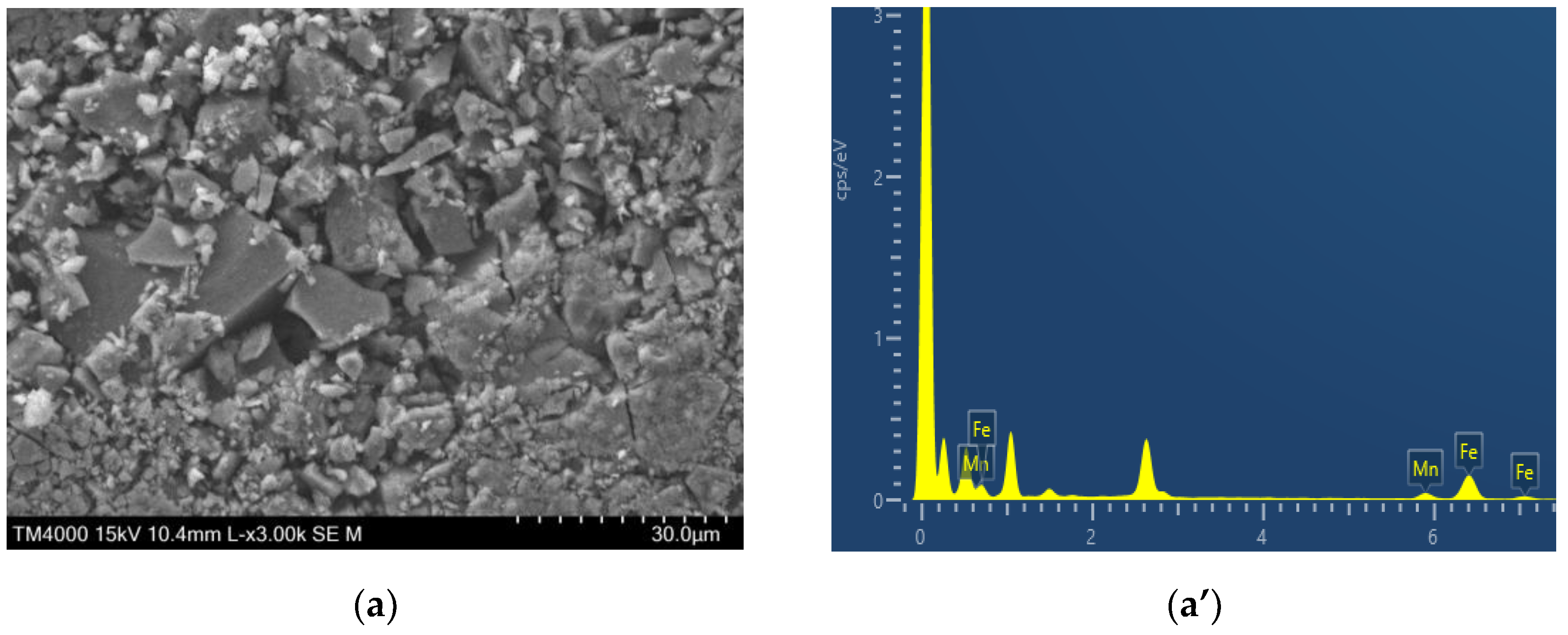
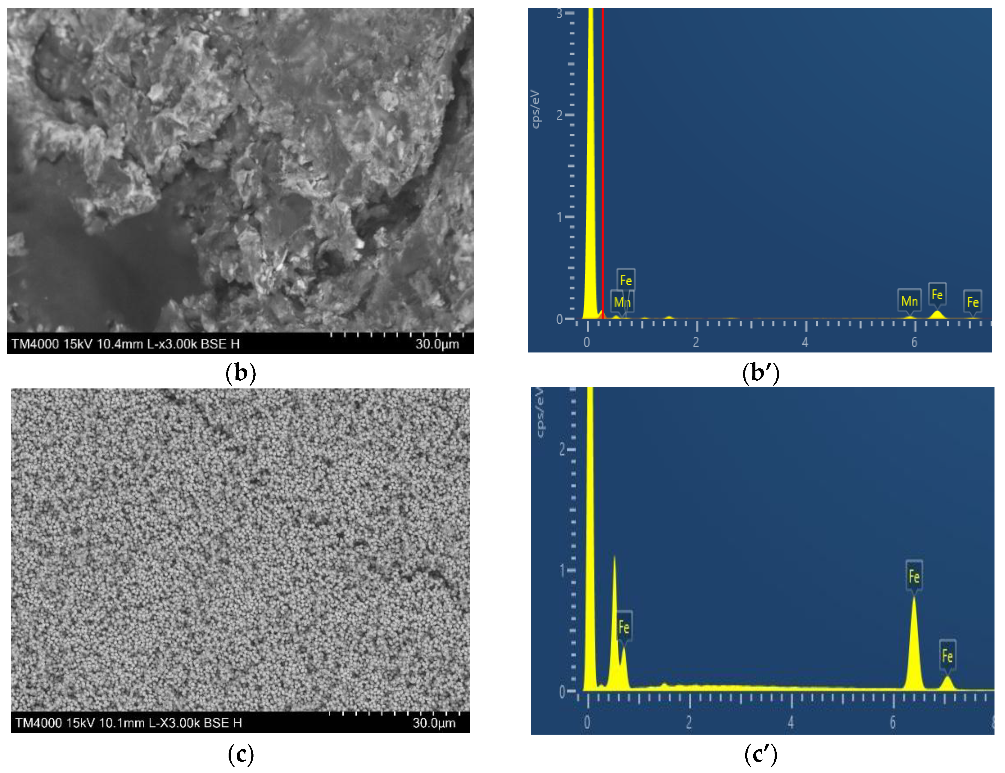
Figure 2.
(a) presents the survey map of the MnFe/N-C catalyst. The maps (b–d) show the distribution of the individual elements: C (b), Fe (c), and Mn (d).
Figure 2.
(a) presents the survey map of the MnFe/N-C catalyst. The maps (b–d) show the distribution of the individual elements: C (b), Fe (c), and Mn (d).
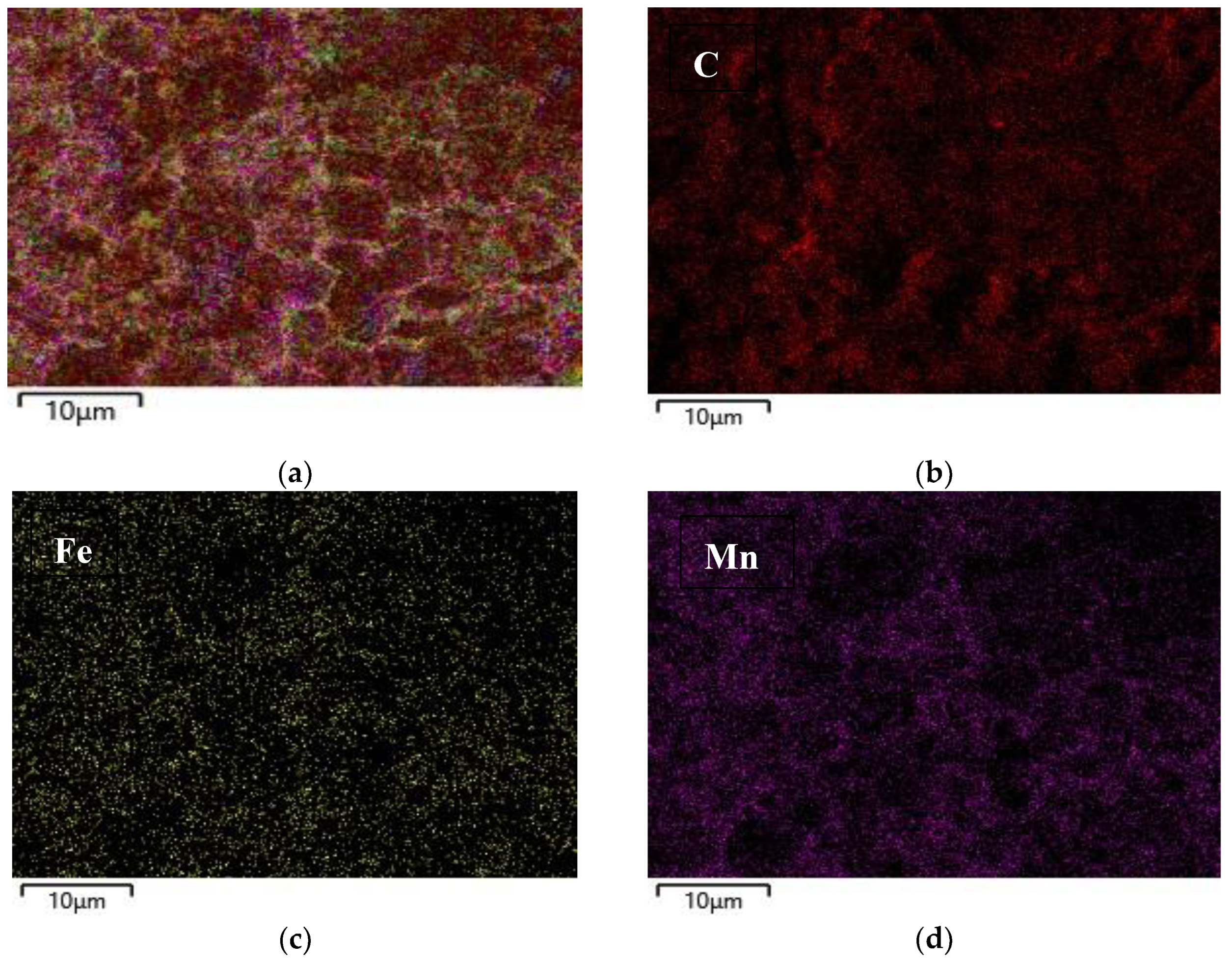
Figure 3.
XRD patterns of the Fe/N-C (a) and MnFe/N-C (b) catalysts. Peaks positions are indicated according to Crystallography Open Database (COD) data cards: Fe2O3—1011240; MnFe2O4—1010131.
Figure 3.
XRD patterns of the Fe/N-C (a) and MnFe/N-C (b) catalysts. Peaks positions are indicated according to Crystallography Open Database (COD) data cards: Fe2O3—1011240; MnFe2O4—1010131.
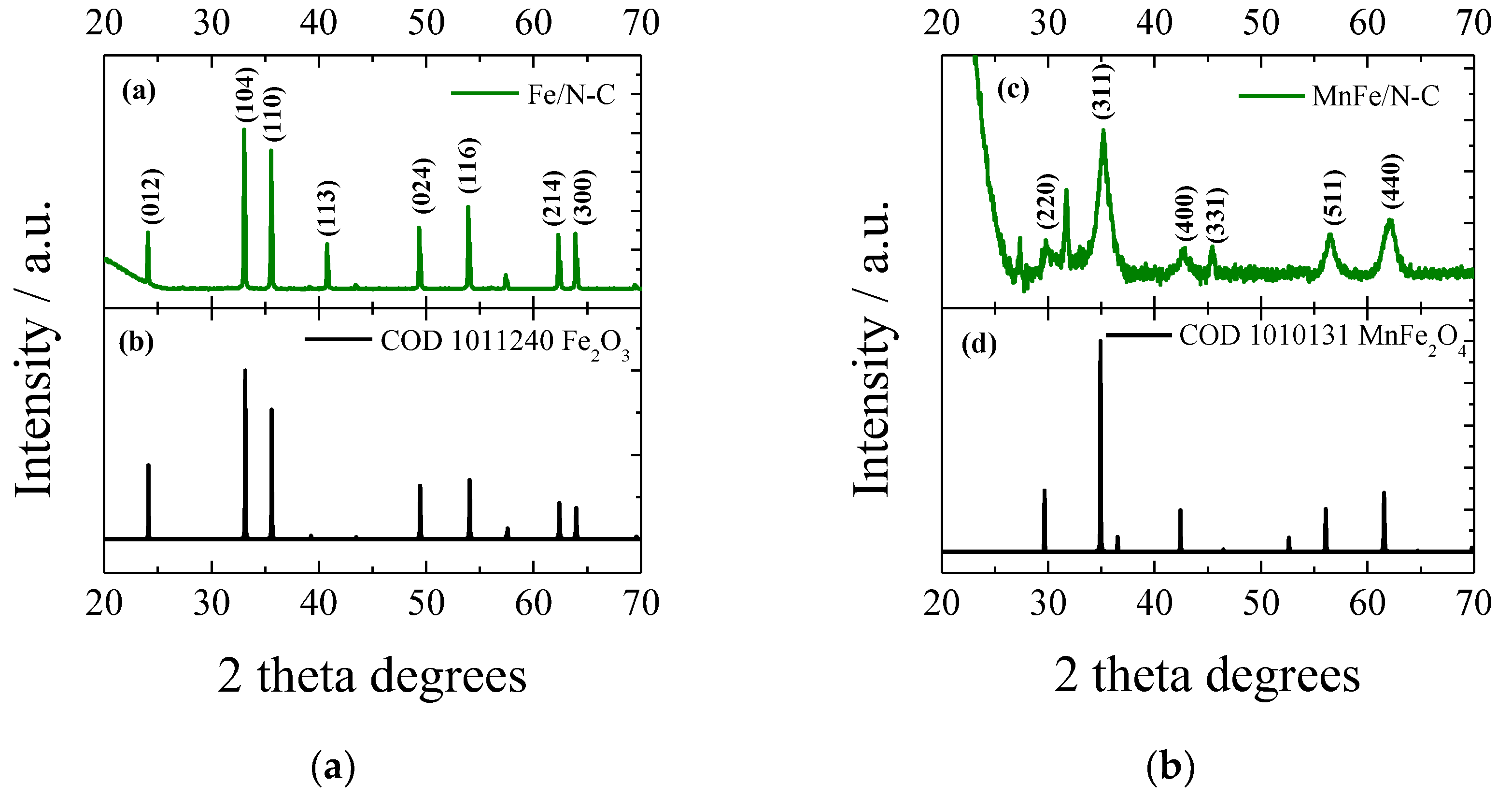
Figure 4.
CVs of the MnFe (a), MnFe/N-C (b), and Fe/N-C (c) catalysts in an N2-saturated 1 M KOH in the non-faradaic potential region at various scan rates (10–50 mV/s). (d).
Figure 4.
CVs of the MnFe (a), MnFe/N-C (b), and Fe/N-C (c) catalysts in an N2-saturated 1 M KOH in the non-faradaic potential region at various scan rates (10–50 mV/s). (d).
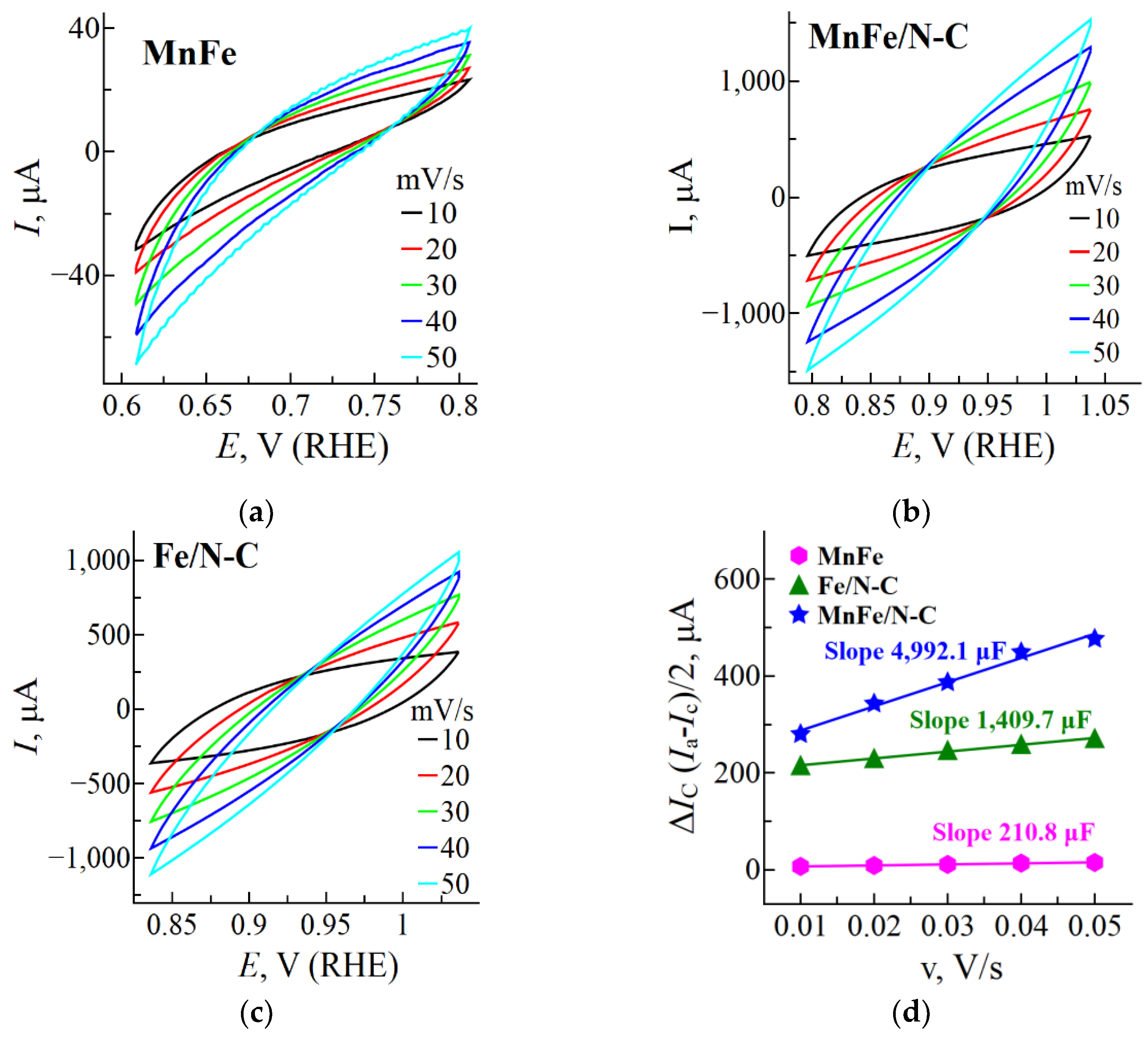
Figure 5.
Comparison of CVs (a) and onset potentials (b) recorded on the MnFe/N-C, MnFe, Fe/N-C, and bare Ti catalysts in a 0.05 M N2H4 + 1 M KOH solution at a scan rate of 50 mV s–1. CVs recorded on MnFe/N-C (c) and MnFe (d) catalysts in a 1 M KOH solution containing 0.01 – 0.2 M N2H4 concentrations at a scan rate of 50 mV s–1. (e) Bar columns of the N2H4 oxidation current densities at MnFe/N-C and MnFe at a potential of +1.6 V. (f) CVs recorded on the MnFe/N-C/Ti catalyst at different scan rates (20–50 mV s–1) in the 0.05 M N2H4 + 1 M KOH solution. (g) Tafel slopes obtained from the data in Figure 5a. (h) Chronoamperometric curve of the MnFe/N-C catalyst at a constant potential of 1.4 V in a 0.05 M N2H4 + 1 M KOH solution.
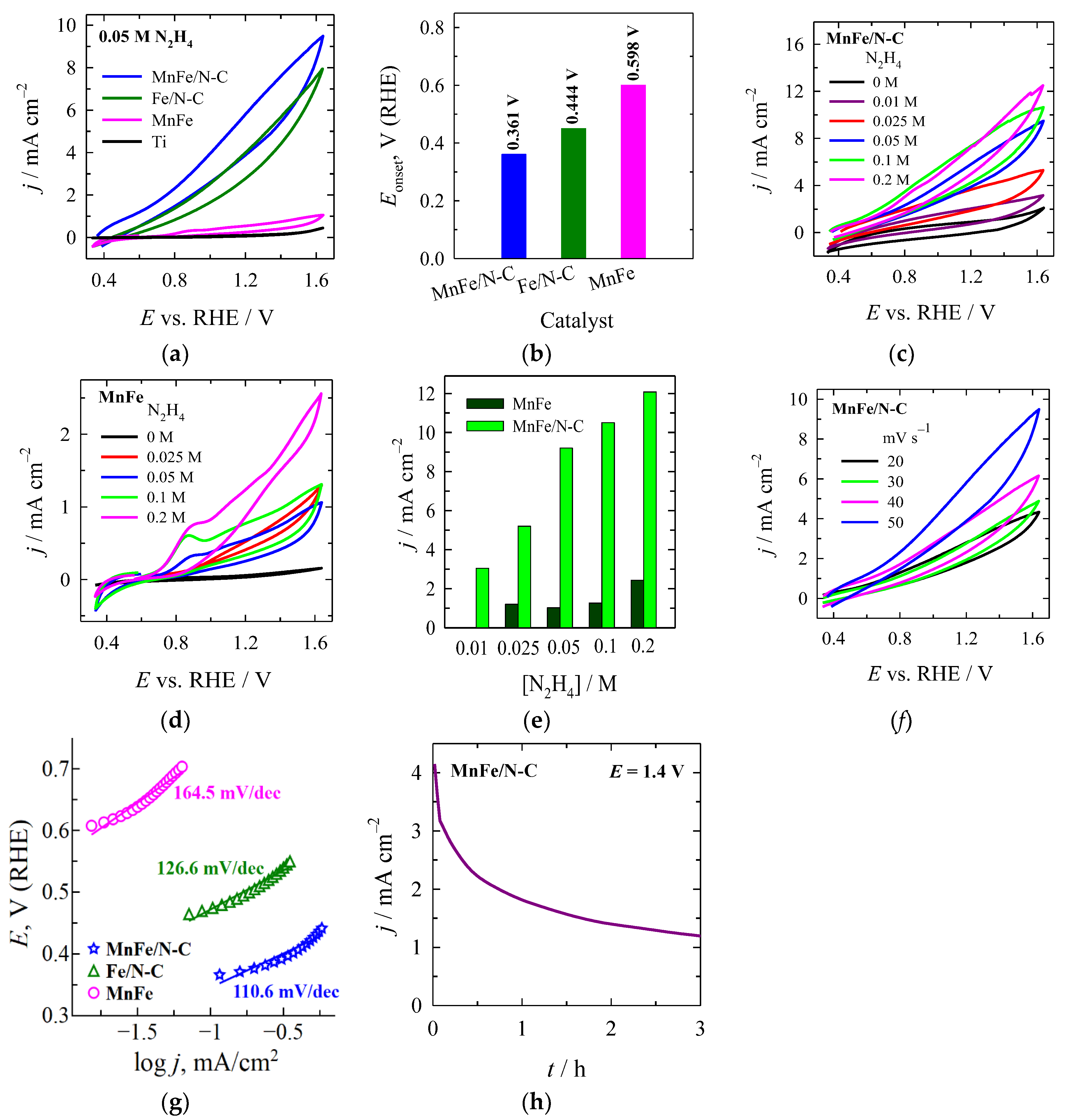
Figure 6.
Scheme for the synthesis of MnFe/N-C catalyst.
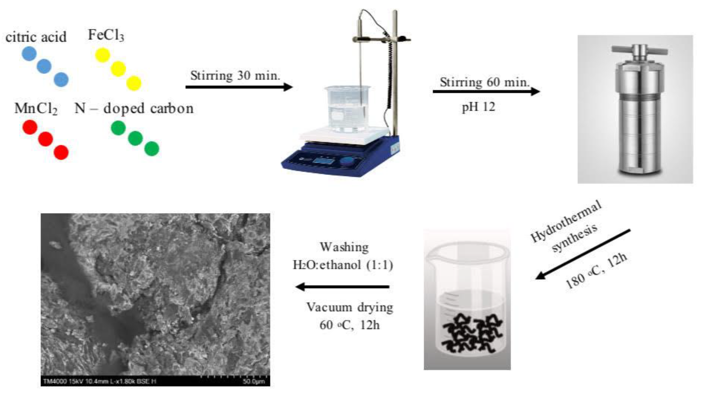

Table 1.
Capacities (Cdl) and ECSA values of the synthesized catalysts.
| Sample | Cdl, µF | ESA, cm2 | Rf |
|---|---|---|---|
| MnFe | 210.8 | 5.3 | 2.6 |
| Fe/N-C | 1,409.7 | 35.2 | 17.6 |
| MnFe/N-C | 4,992.1 | 124.8 | 62.4 |
Table 2.
Comparison of HzOR activity of some recently reported electrocatalysts.
| Sample | Electrolyte | Eonset, V vs. RHE | Ref. |
|---|---|---|---|
| MnO/N-C | 1 M KOH + 0.1 M N2H4 | +0.286 | [32] |
| N-C | 1 M KOH + 0.1 M N2H4 | +0.397 | [32] |
| Ni-Fe/NF | 1 M KOH + 0.5 M N2H4 | −0.110 | [31] |
| Fe–NC-2–1000 | 1 M KOH + 0.1 M N2H4 | +0.350 | [54] |
| Fe2MoC@NC | 1 M KOH + 0.1 M N2H4 | +0.280 | [57] |
| NiCoFe3O4 | 1.0 M KOH + 0.5 M N2H4 | +0.315 | [29] |
| NiFe3O4 | 1.0 M KOH + 0.5 M N2H4 | +0.595 | [29] |
| CoFe3O4 | 1.0 M KOH + 0.5 M N2H4 | +0.657 | [29] |
| Fe-MOF | 1.0 M KOH + 0.5 M N2H4 | +0.604 | [29] |
| Fe3C@NCNTs | 1.0 M KOH + 0.1 M N2H4 | +0.270 | [58] |
| SeNCM-1000 | 1.0 M KOH + 0.1 M N2H4 | +0.340 | [59] |
| Porous carbon-derived from filter paper (PCDFs-900) | 0.1 M PBS (pH 7.4) + 0.05 M N2H4 | +0.378 | [60] |
| Fe2O3/ECP-15 | 1.0 M KOH + 0.1 M N2H4 | +0.610 | [61] |
| Fe/N-C | 1.0 M KOH + 0.05 M N2H4 | +0.444 | This study |
| MnFe/N-C | 1.0 M KOH + 0.05 M N2H4 | +0.361 | This study |
Disclaimer/Publisher’s Note: The statements, opinions and data contained in all publications are solely those of the individual author(s) and contributor(s) and not of MDPI and/or the editor(s). MDPI and/or the editor(s) disclaim responsibility for any injury to people or property resulting from any ideas, methods, instructions or products referred to in the content. |
© 2025 by the authors. Licensee MDPI, Basel, Switzerland. This article is an open access article distributed under the terms and conditions of the Creative Commons Attribution (CC BY) license (http://creativecommons.org/licenses/by/4.0/).
Copyright: This open access article is published under a Creative Commons CC BY 4.0 license, which permit the free download, distribution, and reuse, provided that the author and preprint are cited in any reuse.


