
Submitted:
24 November 2025
Posted:
25 November 2025
You are already at the latest version
Abstract
Enhancing the local mechanical response of low-carbon cast steels remains essential for improving their performance in wear-intensive environments. In this work, a low-carbon cast steel was locally modified through the in situ formation of TiC particles via melt reaction with pressed Ti–Al–C powders. Advanced microstructural characterization (SEM/EDS, EBSD, and TEM) revealed a heterogeneous TiC-reinforced composite microstructure containing ~36 vol.% TiC with particle sizes between 0.73 and 3.88 μm. The reinforced region exhibited a substantial increase in hardness, from 160 ± 5 HV30 in the base steel to 407 ± 78 HV30, resulting from the synergistic contribution of TiC particles, fine κ-carbides, and a martensitic matrix. Nanoindentation revealed a strong mechanical contrast between phases, with TiC achieving 25.70 ± 7.76 GPa compared to 4.68 ± 1.09 GPa for the base metal matrix. Micro-abrasion tests showed a 24% reduction in wear rate, accompanied by shallower grooves and reduced plastic deformation. These findings demonstrate that in situ TiC formation, combined with κ-carbide precipitation, provides an effective strategy for improving local hardness and abrasive wear resistance in low-carbon cast steels. The results highlight the potential of in situ composite formation as an effective microstructural engineering strategy for next-generation wear-resistant cast steels.
Keywords:
metal matrix composites (MMCs)
; low-carbon cast steel
; in situ TiC synthesis
; local reinforcement
; casting
; microstructure characterization
; micro-abrasion wear resistance
; structure–property relationships
1. Introduction
Low-carbon cast steels are widely employed in structural and mechanical components due to their excellent formability, weldability, and low production cost. However, their inherently low hardness and limited wear resistance restrict their application in service environments that involve abrasion and impact [1,2,3,4,5]. These limitations have driven increasing interest in surface engineering strategies capable of enhancing local wear performance while preserving the intrinsic toughness of the steel [6,7,8].
Among the available approaches, metal matrix composites (MMCs) reinforced with hard ceramic phases have proven highly effective [6,7]. These reinforcements can be introduced through ex situ methods, such as embedding pre-synthesized particles (e.g., WC) [9] or applying hard coatings by thermal spraying or brazing [6]. Alternatively, reinforcement can be generated in situ through direct reaction between the molten metal and powders of selected elements, forming hard particles during casting [9,10,11]. While ex situ approaches have been successfully applied to a variety of matrix systems, they often exhibit drawbacks such as weak interfacial bonding and non-uniform particle dispersion, especially in large or complex components [1,2]. In contrast, in situ methods generally offer superior wettability, stronger matrix–particle interfaces, and the potential to produce graded composite layers enriched with fine carbide particles [9,10,11]. These advantages have been demonstrated in systems such as WC–Fe composites [8] and in TiC-based MMCs, which are gaining relevance due to their high hardness, thermal stability, and chemical compatibility with iron-based matrices [6,7,9].
Recent research has explored the in situ synthesis of TiC-based MMCs during steel casting, particularly using compacted preforms containing Ti, graphite, and Al powders [9,12,13]. The exothermic reaction between the powders and the molten steel promotes the precipitation of TiC within the ferrous matrix, while secondary phases such as κ-carbides or aluminides may form depending on local thermochemical interactions and heat dissipation [12,13,14]. The resulting composite zones typically show significant improvements in hardness—often three to four times that of the base metal—and substantial reductions in wear rate, as reported in TiC- and WC-reinforced cast steels [8,9,13,15,16,17]. Olejnik et al. further highlight the potential of in situ reinforcements as a low-cost, easily deployable solution for upgrading the wear performance of cast components without specialized processing equipment [13,15,16]. Despite the growing maturity of the in situ reinforcement concept, several challenges remain. Achieving sufficient homogeneity in reinforcement distribution, particle size, and morphology, and controlling residual porosity are essential to ensure consistent local mechanical and tribological response. Moreover, the formation and influence of secondary phases, such as κ-carbides and aluminides, and the detailed relationships among processing parameters, microstructural evolution (including matrix transformation), and mechanical performance remain incompletely understood. There is a relative scarcity of studies that combine comprehensive microstructural characterization with local mechanical testing and wear measurements in low-carbon cast steels locally reinforced with in situ TiC.
In this context, this work investigates the microstructure, mechanical response, and abrasive wear behavior of a low-carbon cast steel locally reinforced with in situ TiC particles produced from Ti–Al–C preforms. Particular emphasis is placed on multiscale microstructural characterization using EBSD and TEM, and on establishing correlations between microstructural features, hardness (including nanoindentation), and micro-abrasion wear resistance. The results aim to provide new insight into the design of locally reinforced cast steels for abrasive service conditions.
2. Materials and Methods
2.1. Raw Materials and Preforms Fabrication
Commercial titanium (Ti) powders (99.5 wt.%) from Alfa Aesar–ThermoFisher (Kandel, Germany), aluminum (Al) powders (99.0 wt.%) from Goodfellow Cambridge Ltd., and graphite (99.0 wt.%) from Alfa Aesar–ThermoFisher (Kandel, Germany) were used to prepare compacted preforms for insertion into a sand mold cavity. The powders were weighed to the nominal composition of 64 wt.% Ti – 20 wt.% Al – 16 wt.% C, homogenized for seven hours in a Turbula shaker–mixer (Willy A. Bachofen AG, Muttenz, Switzerland), and uniaxially cold-pressed at ≈230 MPa in a martensitic stainless-steel die to obtain parallelepiped preforms with dimensions of 31 × 12 × 3 mm3.
2.2. Casting of the Reinforced Specimens and Heat Treatment
The preforms were positioned at predefined locations within the sand mold cavity before pouring low-carbon steel at 1620 °C, allowing the exothermic reaction between Ti and carbon (C) (assisted by Al). The chemical composition of the low-carbon steel was analyzed by optical emission spectrometry (MAXx LMM05, Spectro, Germany) according to ISO 4991:2024 [18], yielding: 0.22 wt.% C, 0.43 wt.% Si, 0.91 wt.% Mn, 0.10 wt.% Cr, 0.09 wt.% Ni, 0.03 wt.% Cu, and balance Fe. After solidification, the reinforced specimens (Ø45 × 48 mm3) were normalized at 930 °C for 30 min. This treatment is usually applied to cast components to refine the microstructure and relieve stress.
2.3. Metallographic Preparation
Cross-sections of the reinforced specimens were cut by wire electrical discharge machining (EDM), followed by grinding and polishing using standard metallographic procedures. Nital 2% reagent was applied to reveal matrix constituents and carbide morphologies.
2.4. Microstructural Characterization
Microstructural analysis was performed using scanning electron microscopy with energy-dispersive X-ray spectroscopy (SEM/EDS) on a FEI QUANTA 400 FEG (FEI Company, Hillsboro, OR, USA), operating with secondary-electron (SE) and backscattered-electron (BSE) detectors. Titanium carbide (TiC) particle size and volume fraction were quantified from BSE micrographs using an automated ImageJ (v1.52, NIH, Bethesda, MD, USA) routine. Particle size was defined as the average of the two most extended mutually perpendicular chords; 350 particles were measured. The TiC volume fraction was obtained by segmentation of 20 arbitrary images (2000× magnification).
Electron backscatter diffraction (EBSD) was used to assist phase identification across the reinforced region. EBSD analyses were performed in a field-emission SEM equipped with an EDAX Pegasus X4M system. Orientation maps were acquired at an accelerating voltage of 15 kV, with the step size selected according to the magnification used for each region, and indexed using the OIM software database for bcc ferrite/martensite (α/α’), TiC, and κ-carbides. Post-processing involved standard noise reduction procedures, including grain confidence index (CI) clean-up with a grain tolerance angle of 15° and a minimum grain size of 10 points, to remove isolated, incorrectly indexed pixels.
X-ray diffraction (XRD) patterns of the composite zone (CZ) and base metal (BM) were collected on a Bruker D8 θ–θ diffractometer (Bruker Corporation, Billerica, MA, USA) using Cu Kα radiation (λ = 1.5406 Å) generated at 40 kV and 40 mA, with a β-filter and no monochromator. Data were acquired over the 2θ range from 30° to 90°, with a step size of 0.04° and a 1 s counting time per step. The diffraction profiles were used to identify the constituent phases in the CZ and BM.
For transmission electron microscopy, electron-transparent lamellae were prepared by dual-beam focused ion beam (FIB) milling using a FEI Helios NanoLab 450S (FEI Company, Hillsboro, OR, USA). TEM analyses were carried out on a probe-corrected FEI Titan G2 80–200 kV ChemiSTEM. Selected-area electron diffraction (SAED) was used to identify crystallographic phases. In STEM mode, EDS mapping was used to determine the chemical composition of the phases; quantitative EDS results were obtained using ZAF corrections.
2.5. Hardness Characterization
The Vickers macrohardness was measured in both the CZ and the BM (seven indents per region) using a DuraVision 20 universal hardness tester (EMCO-TEST Prüfmaschinen GmbH, Kuchl, Austria) with a 294.2 N load, in accordance with ISO 6507-1:2023 [19]. Due to the small size of the TiC particles, instrumented nanoindentation was performed on a NanoTest system (Micro Materials Ltd., Wrexham, UK) using a Berkovich diamond indenter and a maximum load of 30 mN. A total of 28 tests were performed in the composite zone (CZ), targeting TiC particles and the martensitic (α’) matrix, with a 50 μm spacing between indents. Tests were load-controlled, starting at 0.05 mN, with loading and unloading rates of 5 mN·s⁻¹, and a dwell period of 5 s at maximum load to minimize creep effects. Thermal drift correction used 30 s of post-indentation data acquisition. Load-displacement curves were analyzed using a power-law fit to the unloading segment (100–20% of maximum load) and the Oliver-Pharr method to extract hardness values.
2.6. Micro-Abrasion Characterization
The wear behavior was evaluated using a Plint TE66 micro-scale abrasion tester (Plint & Partners Ltd., Newbury, UK) in a ball-cratering configuration, following ISO 26424:2008 [20]. Tests employed a 25 mm steel ball rotating at 80 rpm under a load of 0.25 N, with sliding distances of 7.9, 15.7, 23.6, and 31.4 m. The abrasive slurry consisted of SiC grade F1200 at 0.35 g·cm⁻3. Wear craters were measured optically and, when needed, analyzed by SEM. Wear volume was calculated from crater geometry, and wear-rate coefficients were obtained from the slope of wear volume vs. sliding distance following the Archard relationship. Three samples were tested per condition.
3. Results and Discussion
3.1. Microstructural Characterization
The casting route produced a continuous, approximately two mm-thick titanium carbide (TiC)-reinforced composite zone (CZ) metallurgically bonded to the base metal (BM), as shown in the SEM–BSE images in Figure 1. At low magnification, the CZ appears as a continuous layer over the BM (Figure 1a). Higher-magnification images (Figure 1c,d) reveal a sound metallurgical bond across the CZ–BM interface, with almost no evidence of voids or porosity. This observation indicates an effective infiltration of the Ti-Al-C preform by the molten steel. Such behavior can be explained by the melting of Al, which enhances wetting of the preform and improves interfacial bonding between the composite and the steel matrix [14].
Elemental mapping further supports this interpretation: the energy-dispersive spectroscopy (EDS) maps in Figure 2 indicate that the composite matrix, in addition to Fe (Figure 2b), is enriched in aluminum (Al) (Figure 2d). Small particles rich in Al, probably Al-oxide particles formed by the reaction of Al with oxygen during casting, are also observed. Ti-rich regions (Figure 2c) correspond to the semi-continuous TiC networks.
As shown in Figure 1 and Figure 2, the TiC presents a non-homogeneous distribution. This configuration, previously described as a cellular structure similar to that observed in metallic foams [21,22], is typically associated with local variations in reaction kinetics, heat extraction, and compacting density of the preform.
X-ray diffraction results (Figure 3) indicate that the BM displays only ferrite (α) indexed peaks. In contrast, the CZ reveals reflections from TiC, some of which overlap with the (110), (200), and (211) peaks of the ferrite/martensite (α/α′) matrix. These findings confirm that TiC is the primary hard phase in the CZ, thereby validating the effectiveness of the in situ TiC synthesis employed in this study. Notably, titanium aluminides (TiAlₓ, x = 1, 3) were not detected in the XRD patterns, suggesting that the combustion reaction between Ti and graphite has proceeded to completion (with Al acting primarily as a mediator in the melt reaction rather than forming stable aluminides), which is consistent with the observations of Song et al. [23].
In addition, electron backscatter diffraction (EBSD) point analyses were performed at multiple locations within the CZ, selecting regions with different phase distributions (see Figure 4, Figure 5 and Figure 6), to corroborate the SEM and XRD results. Figure 4 shows nearly spherical TiC particles embedded in a α’ matrix, with some colonies of lamellar pearlite; almost no agglomerates of TiC particles were noted. Figure 5 presents a TiC network evidencing the random orientation of the particles (Figure 5c). The IPF maps also confirm that the surrounding metallic matrix is predominantly α’. The band-contrast/IQ map (Figure 5d) reveals clean TiC/matrix interfaces and minimal porosity, confirming effective infiltration and good interfacial bonding. In Figure 6, the EBSD results confirm the presence of a κ-carbide phase associated with the Al-rich areas identified by EDS (Figure 2d). This κ-carbide is enriched in Fe and Al, which is consistent with the κ-type carbides formed in Al-bearing steels (Fe–Mn–Al carbides) [24,25,26]. The formation of κ-carbide can be explained by local Al–C supersaturation due to the diffusion of Al and C from the preform into the molten steel, making them locally available to bond with Fe and Mn to form κ-carbides.
High-angle annular dark field scanning transmission electron microscopy (HAADF-STEM) combined with selected area electron diffraction (SAED) analysis of the CZ confirmed the in situ formation of near-round TiC with a cubic NaCl-type (B1) structure (space group Fm-3m) and κ-carbides with a cubic antiperovskite (E21) structure (space group Pmm) embedded in an α’ matrix, as shown in Figure 7. STEM-EDS maps (Figure 8) support the SEM/XRD evidence for in situ TiC formation and the presence of Al-rich phases.
The characterization of the CZ was completed by quantifying the TiC amount and particle size. The TiC content, measured by image segmentation of SEM–BSE micrographs, varied from 19% to 45% with an average of 36%, confirming a significant variation in the TiC distribution. The particle-size statistics are summarized in Figure 9: the histogram follows an approximately normal distribution, with minimum and maximum equivalent diameters of 0.73 μm and 3.88 μm, respectively; the cumulative frequency curve indicates that 50% of the analyzed particles are smaller than 1.78 μm. These results are consistent with those reported by He et al. for TiC–Fe composites produced via SHS, supporting the representativeness of the present measurements. This broad distribution reflects the intrinsic heterogeneity of the combustion reaction, but ensures the presence of a mechanically robust TiC skeleton within the CZ.
Overall, the composite microstructure consists of near-round TiC particles forming a heterogeneous but continuous reinforcement framework, embedded in a α’ matrix strengthened by locally distributed κ-carbides. This multiscale architecture underpins the mechanical and wear responses described below.
3.2. Mechanical Characterization
3.2.1. Hardness Results
Macrohardness measurements (Figure 10) show a substantial strengthening effect in the composite zone (CZ), with the CZ reaching 407 ± 78 HV 30, approximately 2.5 times the hardness of the Base metal (BM) (160 ± 5 HV 30). This relative hardening is comparable to that reported for a cast steel locally reinforced with a WC–metal matrix composite [8]. Hardness values reported for in situ titanium carbide (TiC)-reinforced zones vary widely in the literature due to differences in matrix composition, reaction moderators, Ti/C ratios, and processing routes. For example, TiC/FeMn local reinforcements formed in situ in a low-alloy manganese-silicon-molybdenum cast steel can reach 550–800 HV 30 when manufactured with elevated TiC content [13], while the TiC–Fe composite prepared in situ by self-propagating high-temperature synthesis combined with vacuum expendable pattern casting can exceed 800 HV when produced as a surface coating with a high TiC loading [27]. Despite some similarities, such systems are not directly comparable to current reinforced low-carbon steel. In this context, the measured increase in hardness is consistent with the expected response for a low-carbon cast steel locally reinforced with in situ synthesized TiC, confirming the effectiveness of the reinforcement mechanism despite the heterogeneity of the TiC distribution.
Nanoindentation measurements (Figure 11) clarify the intrinsic contribution of each phase. TiC particles exhibit an average hardness of 25.70 GPa, while the surrounding martensitic (α′) matrix shows only 4.68 GPa. TiC is therefore approximately 5.5 times harder than the matrix, which reinforces its role as the primary load-bearing and abrasion-resistant phase in the CZ.
3.2.2. Micro-abrasion Wear Behavior
Abrasive wear results are presented in Figure 12, where wear volume (V) is plotted as a function of sliding distance (S) for the composite zone (CZ) and the base metal (BM). A clear linear V–S relationship is observed, indicating a nearly constant wear rate under the 0.25 N load (steady micro-abrasion regime). The slope of the best-fit line to the experimental points corresponds to the wear-rate coefficient K in the Archard equation (V = K×S) [28,29]. Notably, the CZ exhibits a significantly lower wear rate than the BM, corresponding to a ≈24% reduction in K. This improvement is comparable to the lower limit of the wear-rate reductions reported for locally reinforced cast steels and irons: WC–MMC produced on low-carbon cast steel under similar ball-cratering conditions exhibited a ≈39% decrease in wear rate relative to the BM [8], while TiC- and WC-reinforced high-Cr white irons showed reductions of ≈30% and ≈60%, respectively, depending on the type and volume fraction of carbides [9]. Larger decreases (up to 67–76% lower wear volume or even order-of-magnitude improvements in wear index) have been reported in Mn-steel and FeMn systems containing very high TiC contents or optimized TiC/TiB₂ [7,13,15,16,27], so the present results place in situ TiC-reinforced low-carbon cast steel in the lower–intermediate range of wear-resistance improvements achievable by local composite reinforcements.
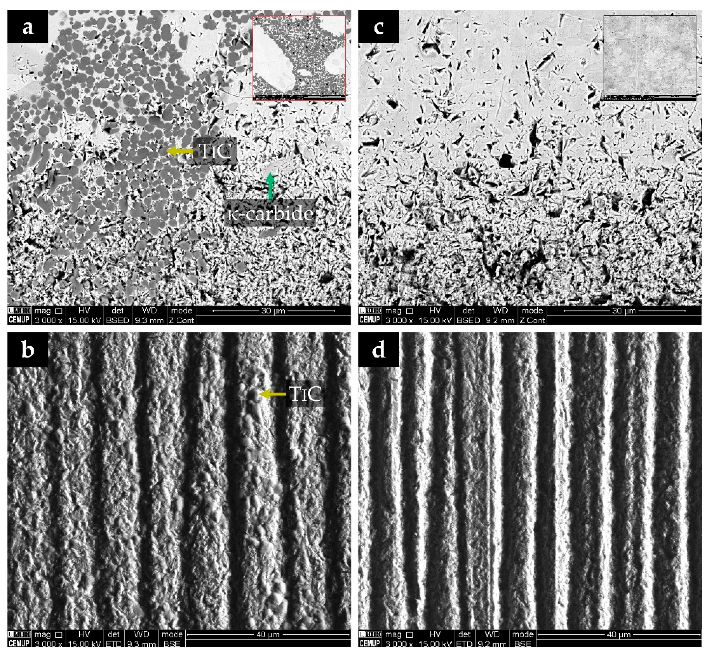
SEM analyses of the wear craters (Figure 13) clarify the governing wear mechanisms. In the TiC-reinforced zone (Figure 13a,b), the metallic matrix is the region most affected by abrasion. In contrast, the TiC particles show minimal damage and no evidence of fracture or pull-out, indicating adequate particle–matrix bonding. Compared with unreinforced steel, the reinforced surface exhibits shallower grooves aligned with the sliding direction and reduced plastic deformation, consistent with the suppression of micro-ploughing/micro-cutting by the hard TiC phase. In contrast, the BM (Figure 13c,d) presents a dense array of evenly spaced grooves with marked plastic flow along the track, characteristic of abrasive micro-ploughing in a soft ferritic–pearlitic microstructure. While the overall influence of κ-carbides is less pronounced than that of TiC (see Figure 13a,b), κ precipitates exhibit higher wear resistance than the surrounding matrix, providing a secondary yet beneficial contribution to mitigating local damage. Similar behavior has been described for in situ TiC and TiC–TiB₂ reinforced matrices, where the hard particles act as rigid load-bearing islands that suppress severe micro-ploughing and micro-cutting in their vicinity. In contrast, the softer matrix accommodates most of the deformation and material loss [9,13,15,16,27].
4. Conclusions
In this work, in situ titanium carbide (TiC)-reinforced composite zones were successfully produced in a low-carbon cast steel using Ti–Al–C preforms. The casting route generated a TiC-rich composite metallurgically bonded to the steel, composed of a heterogeneous dispersion of near-round TiC particles embedded in a martensitic (α’) matrix containing dispersed κ-carbides. The composite zone (CZ) exhibited a pronounced increase in hardness, reaching 407 ± 78 HV 30, approximately 2.5 times that of the base metal (BM) (160 ± 5 HV 30). Nanoindentation highlighted TiC as the primary load-bearing, abrasion-resistant phase. Ball-cratering micro-abrasion tests showed that the TiC-reinforced zone has a ~24% lower wear-rate coefficient K than the base steel under identical conditions. SEM observations of the wear craters revealed preferential removal of the metallic matrix, with TiC particles remaining largely intact and in relief, and κ-carbides acting as locally harder regions within the α’ matrix. Overall, the results demonstrate that in situ TiC reinforcement, using a processing route compatible with conventional foundry practice, offers a viable strategy for the design of locally reinforced cast components for abrasive service. Significantly, the method relies on processing steps fully compatible with conventional foundry practice, offering a practical pathway for designing locally reinforced cast components intended for abrasive service conditions.
Author Contributions
Conceptualization, A.B.M.; Formal analysis, L.M.M.R. and M.F.V.; Funding acquisition, M.F.V.; Investigation, A.B.M.; Supervision, L.M.M.R. and M.F.V.; Validation, L.M.M.R. and M.F.V.; Writing—original draft, A.B.M.; Writing—review and editing, A.B.M., L.M.M.R., and M.F.V. All authors have read and agreed to the published version of the manuscript.
Funding
This research was funded by national funds through FCT—Fundação para a Ciência e a Tecnologia, I.P., under project reference UIDB/50022/2020.
Data Availability Statement
The original contributions presented in this study are included in the article. Further inquiries can be directed to the corresponding author.
Acknowledgments
The authors are grateful to CEMUP (Centro de Materiais da Universidade do Porto) for expert assistance with SEM analyses and to INL (International Iberian Nanotechnology Laboratory) for expert assistance with FIB and STEM investigations conducted in this work.
Conflicts of Interest
The authors declare no conflicts of interest.
References
- Saha, G.; Valtonen, K.; Saastamoinen, A.; Peura, P.; Kuokkala, V.-T. Impact-abrasive and abrasive wear behavior of low carbon steels with a range of hardness-toughness properties. Wear 2020, 450-451, 203263. [Google Scholar] [CrossRef]
- Wang, X.; Chen, Y.; Wei, S.; Zuo, L.; Mao, F. Effect of carbon content on abrasive impact wear behavior of Cr-Si-Mn low alloy wear resistant cast steels. Front. Mater. 2019, 6, 153. [Google Scholar] [CrossRef]
- Chintha, A. Metallurgical aspects of steels designed to resist abrasion, and impact-abrasion wear. Mater. Sci. Technol. 2019, 35, 1133–1148. [Google Scholar] [CrossRef]
- Dossett, J.L.; Totten, G.E. Heat Treating of Carbon and Low-Alloy Steels. In Metals Handbook-Heat Treating of Irons and Steels, Dossett, J.L., Totten, G.E., Eds. ASM International: Materials Park, OH, USA, 2014; Vol. 4D.
- Flenner, P. Carbon Steel Handbook; Electric Power Research Institute: Palo Alto, CA, USA, 2007. [Google Scholar]
- Wang, Y.; Feng, C.; Lin, T.; Zhu, R.; Zhang, J.; Yang, H.; Yi, S.; He, J.; Tu, M.; Wei, G. A Review of Wear-Resistant Coatings for Steel Substrates: Applications and Challenges. Metals 2025, 15, 1231. [Google Scholar] [CrossRef]
- Moreira, A.B.; Ribeiro, L.M.; Vieira, M.F. Production of TiC-MMCs Reinforcements in Cast Ferrous Alloys Using In Situ Methods. Materials 2021, 14, 5072. [Google Scholar] [CrossRef]
- Moreira, A.B.; Ribeiro, L.M.; Lacerda, P.; Pinto, A.M.; Vieira, M.F. A study on a cast steel reinforced with WC–metal matrix composite. Materials 2022, 15, 6199. [Google Scholar] [CrossRef]
- Moreira, A.B.; Ribeiro, L.M.; Lacerda, P.; Vieira, M.F. Characterization of iron-matrix composites reinforced by in situ TiC and ex situ WC fabricated by casting. Metals 2021, 11, 862. [Google Scholar] [CrossRef]
- Zou, B.; Shen, P.; Cao, X.; Jiang, Q. The mechanism of thermal explosion (TE) synthesis of TiC–TiB2 particulate locally reinforced steel matrix composites from an Al–Ti–B4C system via a TE-casting route. Mater. Chem. Phys. 2012, 132, 51–62. [Google Scholar] [CrossRef]
- Liang, Y.; Zhao, Q.; Zhang, Z.; Han, Z.; Li, X.; Ren, L. In situ fabrication of TiC–TiB2 precipitates in Mn-steel using thermal explosion (TE) casting. J. Mater. Res. 2015, 30, 1019–1028. [Google Scholar] [CrossRef]
- Szymański, Ł.; Sobczak, J.J.; Peddeti, K.; Bigos, A.; Tokarski, T.; Maziarz, W.; Olejnik, E.; Chulist, R.; Żak, K.; Bruzda, G. , et al. Production of metal matrix composite reinforced by TiC by reactive infiltration of cast iron into Ti + C preforms. Ceram. Int. 2024, 50, 17452–17464. [Google Scholar] [CrossRef]
- Olejnik, E.; Szymański, Ł.; Tokarski, T.; Opitek, B.; Kurtyka, P. Local composite reinforcements of TiC/FeMn type obtained in situ in steel castings. Arch. Civ. Mech. Eng. 2019, 19, 997–1005. [Google Scholar] [CrossRef]
- Choi, Y.; Rhee, S.-W. Effect of aluminium addition on the combustion reaction of titanium and carbon to form TiC. J. Mater. Sci. 1993, 28, 6669–6675. [Google Scholar] [CrossRef]
- Olejnik, E.; Tokarski, T.; Sikora, G.; Sobula, S.; Maziarz, W.; Szymański, Ł.; Grabowska, B. The Effect of Fe Addition on Fragmentation Phenomena, Macrostructure, Microstructure, and Hardness of TiC-Fe Local Reinforcements Fabricated In Situ in Steel Casting. Metall. Mater. Trans. A 2019, 50, 975–986. [Google Scholar] [CrossRef]
- Olejnik, E. Local composite reinforcements of WC/Fe-C type obtained in-situ via SHS synthesis in gray cast iron castings. J. Alloys Compd. 2025, 1034, 181260. [Google Scholar] [CrossRef]
- Perminov, A.; Günther, P.E.; Ilatovskaia, M.O.; Wei, X.; Volkova, O. Cold crucible induction melting for the fabrication of Fe–xTiC in situ metal Matrix composites: alloying efficiency and microstructural analysis. Adv. Eng. Mater. 2023, 25, 2300627. [Google Scholar] [CrossRef]
- ISO 4991; Steel Castings for Pressure Purposes. International Organization for Standardization: Geneva, Switzerland, 2015.
- ISO 6507-1; Metallic Materials—Vickers Hardness Test—Part 1: Test Method. International Organization for Standardization: Geneva, Switzerland, 2018.
- ISO 26424:2008; Fine Ceramics (Advanced Ceramics, Advanced Technical Ceramics)—Determination of the Abrasion Resistance.
- of Coatings by a Micro-Scale Abrasion Test. International Organization for Standardization: Geneva, Switzerland, 2008.
- Olejnik, E.; Sikora, G.; Sobula, S.; Tokarski, T.; Grabowska, B. Effect of compaction Pressure applied to TiC reactants on the Microstructure and Properties of Composite Zones Produced in situ in steel castings. Mater. Sci. Forum. 2014, 782, 527–532. [Google Scholar] [CrossRef]
- Olejnik, E.; Górny, M.; Tokarski, T.; Grabowska, B.; Kmita, A.; Sikora, G. Composite zones produced in iron castings by in-situ synthesis of TiC carbides. Arch. Metall. Mater. 2013, 58, 465–471. [Google Scholar] [CrossRef]
- Song, M.; Huang, B.; Zhang, M.; Li, J. Study of formation behavior of TiC ceramic obtained by self-propagating high-temperature synthesis from Al–Ti–C elemental powders. Int. J. Refract. Met. Hard Mater. 2009, 27, 584–589. [Google Scholar] [CrossRef]
- Chen, P.; Li, X.; Yi, H. The κ-carbides in low-density Fe-Mn-Al-C steels: A review on their structure, precipitation and deformation mechanism. Metals 2020, 10, 1021. [Google Scholar] [CrossRef]
- Feng, Y.; Song, R.; Wang, Y.; Liu, M.; Li, H.; Liu, X. Aging hardening and precipitation behavior of Fe-31.6Mn-8.8Al-1.38C austenitic cast steel. Vacuum 2020, 181, 109662. [Google Scholar] [CrossRef]
- Burja, J.; Šetina Batič, B.; Balaško, T. Kappa carbide precipitation in duplex Fe-Al-Mn-Ni-C low-density steel. Crystals 2021, 11, 1261. [Google Scholar] [CrossRef]
- He, S.; Fan, X.a.; Chang, Q.; Xiao, L. TiC-Fe-Based Composite Coating Prepared by Self-Propagating High-Temperature Synthesis. Metall. Mater. Trans. B 2017, 48, 1748–1753. [Google Scholar] [CrossRef]
- Ramalho, A. A reliability model for friction and wear experimental data. Wear 2010, 269, 213–223. [Google Scholar] [CrossRef]
- Archard, J.F. Contact and Rubbing of Flat Surfaces. J. Appl. Phys. 1953, 24, 981–988. [Google Scholar] [CrossRef]
Figure 1.
SEM-BSE image of the microstructure of the reinforced specimen, evidencing the BM and the CZ (a); (b) scheme of a reinforced cast specimen; (c) SEM-BSE image of the microstructure of the CZ, and (d) high-magnification of (c).
Figure 1.
SEM-BSE image of the microstructure of the reinforced specimen, evidencing the BM and the CZ (a); (b) scheme of a reinforced cast specimen; (c) SEM-BSE image of the microstructure of the CZ, and (d) high-magnification of (c).
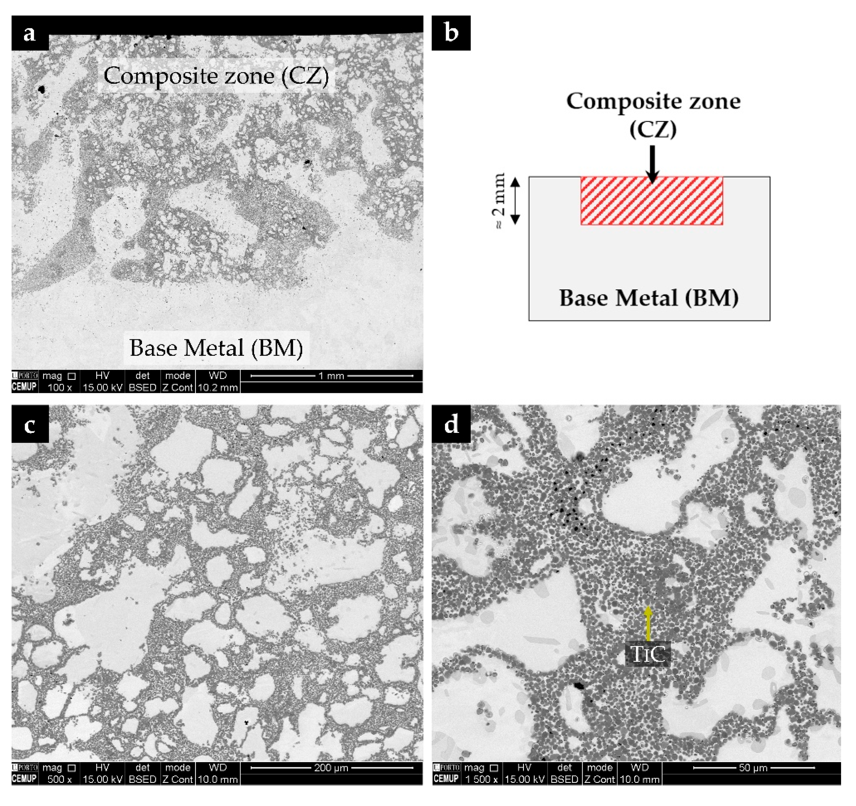
Figure 2.
SEM-BSE image of the microstructure of the CZ (a); EDS elemental mapping (b-Fe, c-Ti, d-Al); superposition of Ti (yellow) and Fe (blue) (e); and of Ti, Fe, and Al (green) (f).
Figure 2.
SEM-BSE image of the microstructure of the CZ (a); EDS elemental mapping (b-Fe, c-Ti, d-Al); superposition of Ti (yellow) and Fe (blue) (e); and of Ti, Fe, and Al (green) (f).
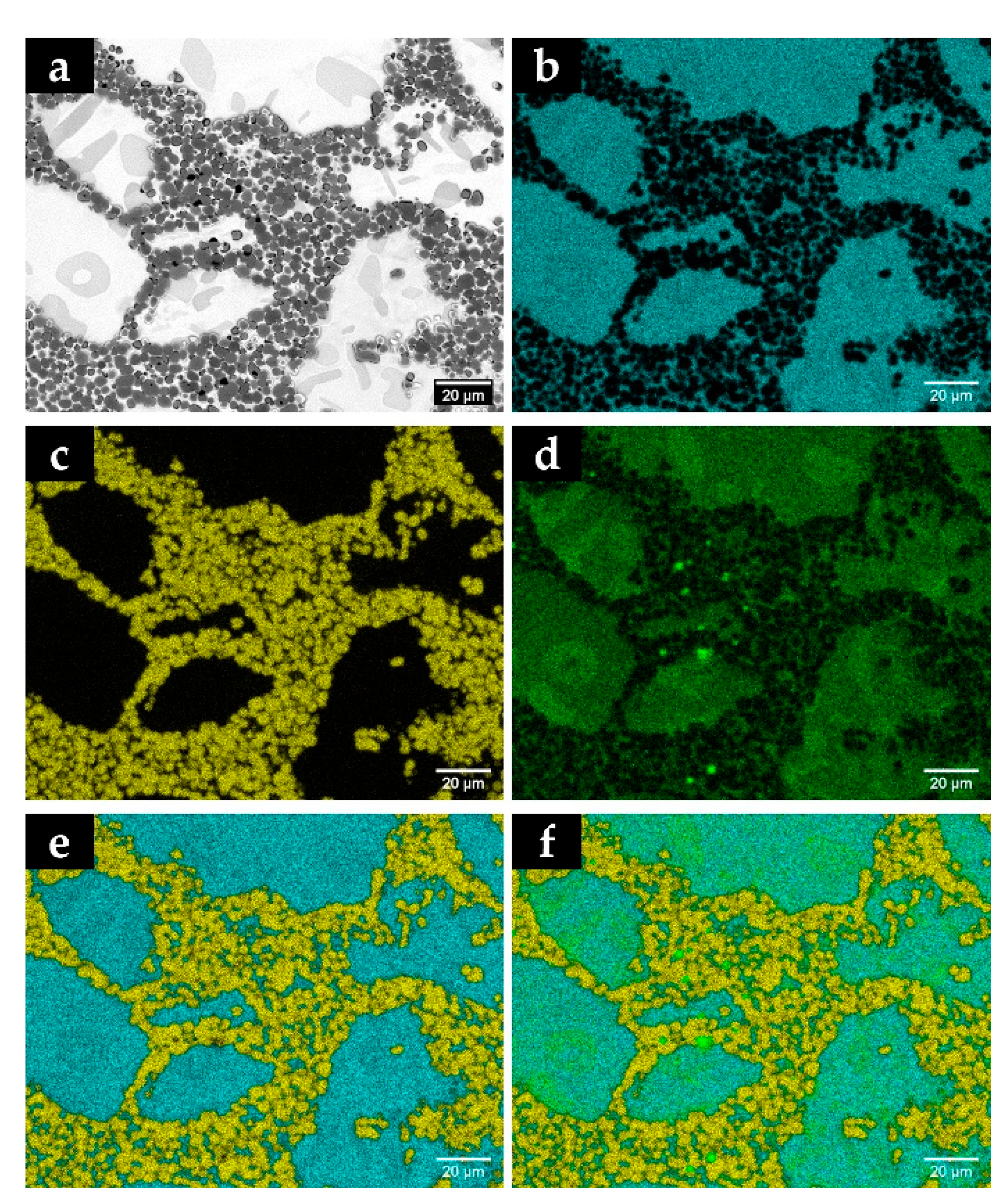
Figure 3.
X-ray diffraction (XRD, Cu Kα) patterns of the base low-carbon steel (black) and the TiC-reinforced CZ (red) after normalizing (930 °C/30 min), scanned over 30°–90° (2θ), identifying the presence of TiC and α/α’ phases.
Figure 3.
X-ray diffraction (XRD, Cu Kα) patterns of the base low-carbon steel (black) and the TiC-reinforced CZ (red) after normalizing (930 °C/30 min), scanned over 30°–90° (2θ), identifying the presence of TiC and α/α’ phases.
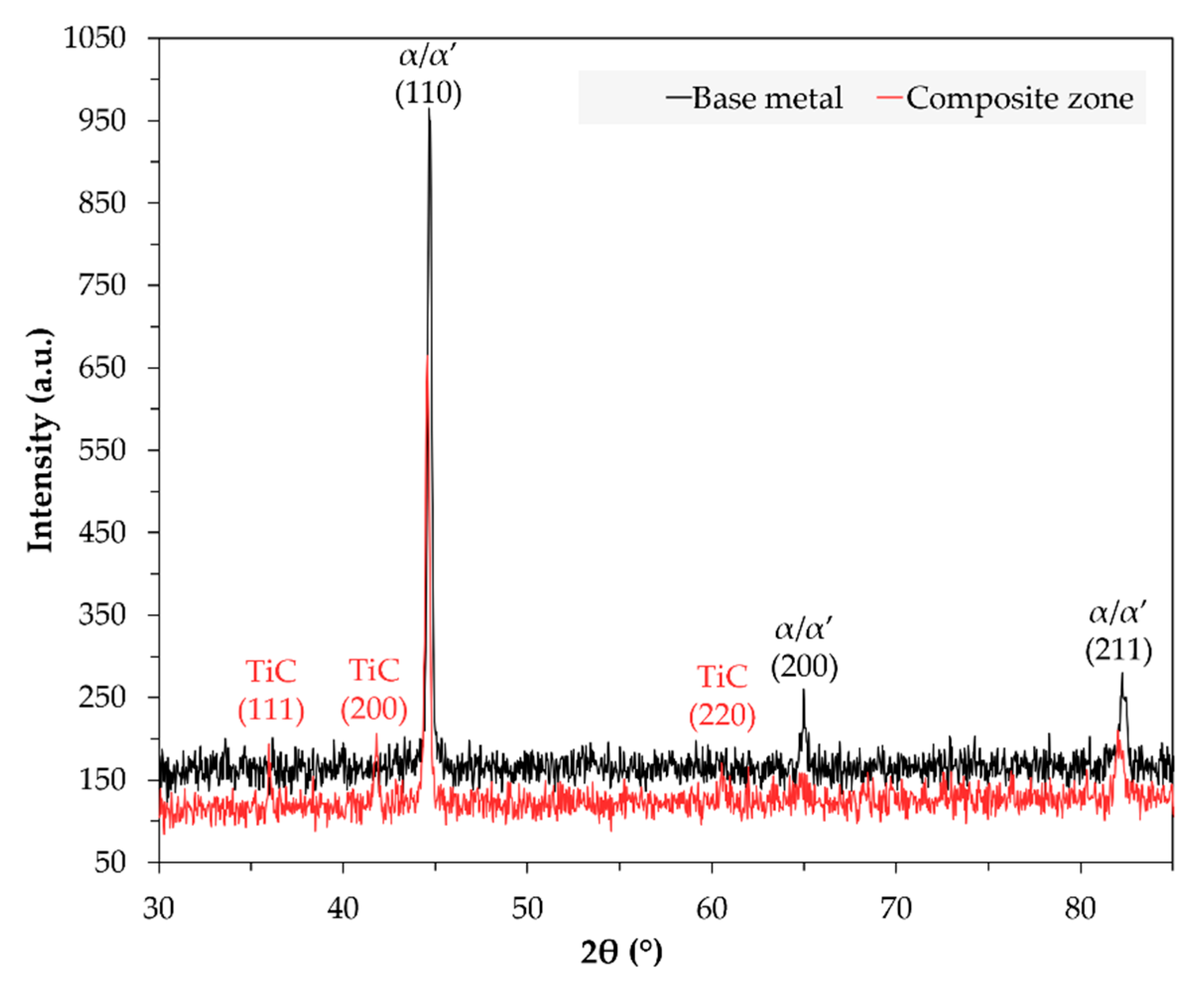
Figure 4.
SEM-BSE image of the CZ with a high amount of dispersed TiC particles (a); SEM-SE image under typical EBSD experimental conditions (tilted sample) of the analyzed zone (b); indexed EBSD patterns corresponding to the phases present in the composite: TiC (c,d) and α’ (e).
Figure 4.
SEM-BSE image of the CZ with a high amount of dispersed TiC particles (a); SEM-SE image under typical EBSD experimental conditions (tilted sample) of the analyzed zone (b); indexed EBSD patterns corresponding to the phases present in the composite: TiC (c,d) and α’ (e).
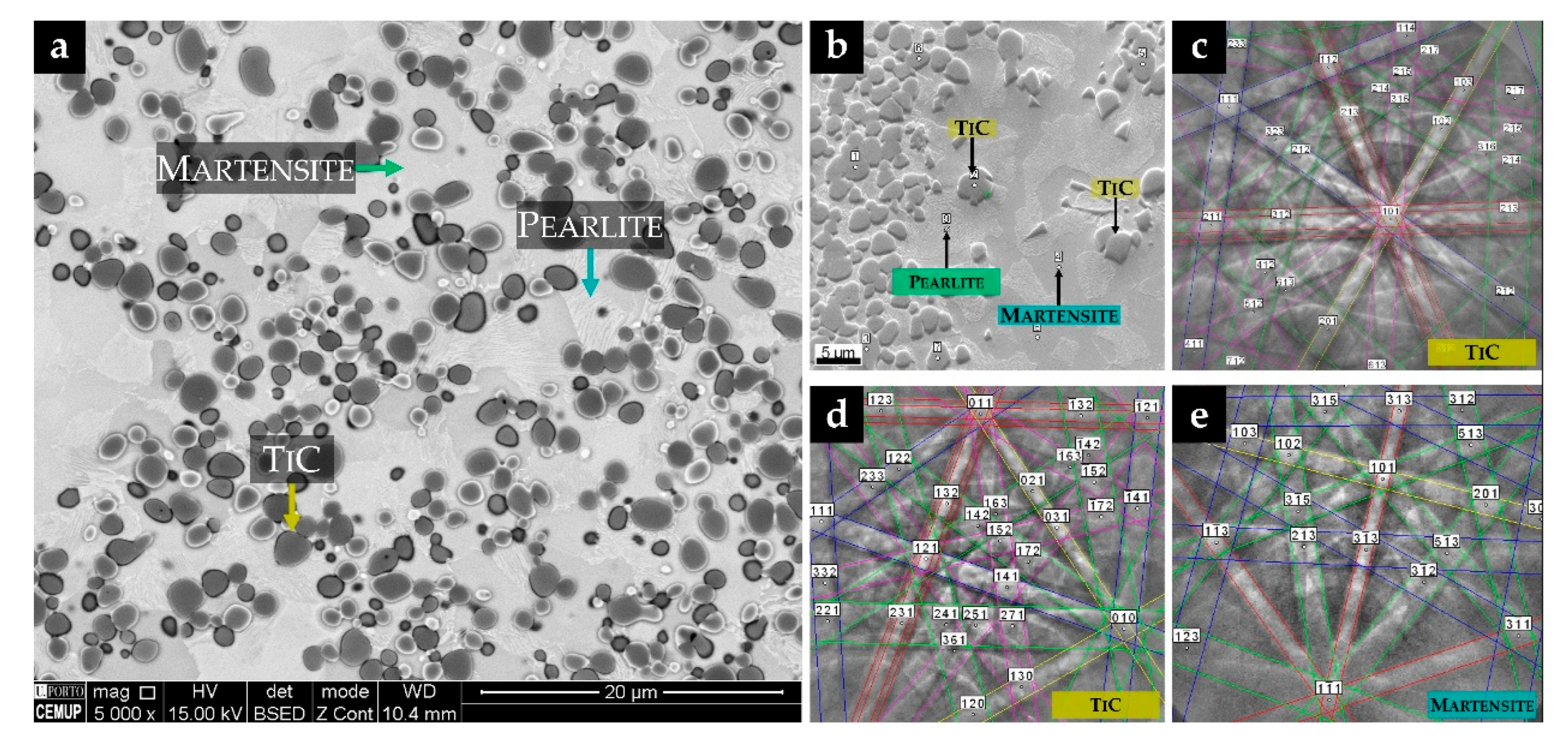
Figure 5.
SEM image in EBSD mode acquisition (tilt of sample) (a); phase map (b); Inverse Pole Figure (IPF) map (c); and image quality map (d). All maps (phase and IPF) have an overlay with the quality map to assess the effectiveness of the results.
Figure 5.
SEM image in EBSD mode acquisition (tilt of sample) (a); phase map (b); Inverse Pole Figure (IPF) map (c); and image quality map (d). All maps (phase and IPF) have an overlay with the quality map to assess the effectiveness of the results.
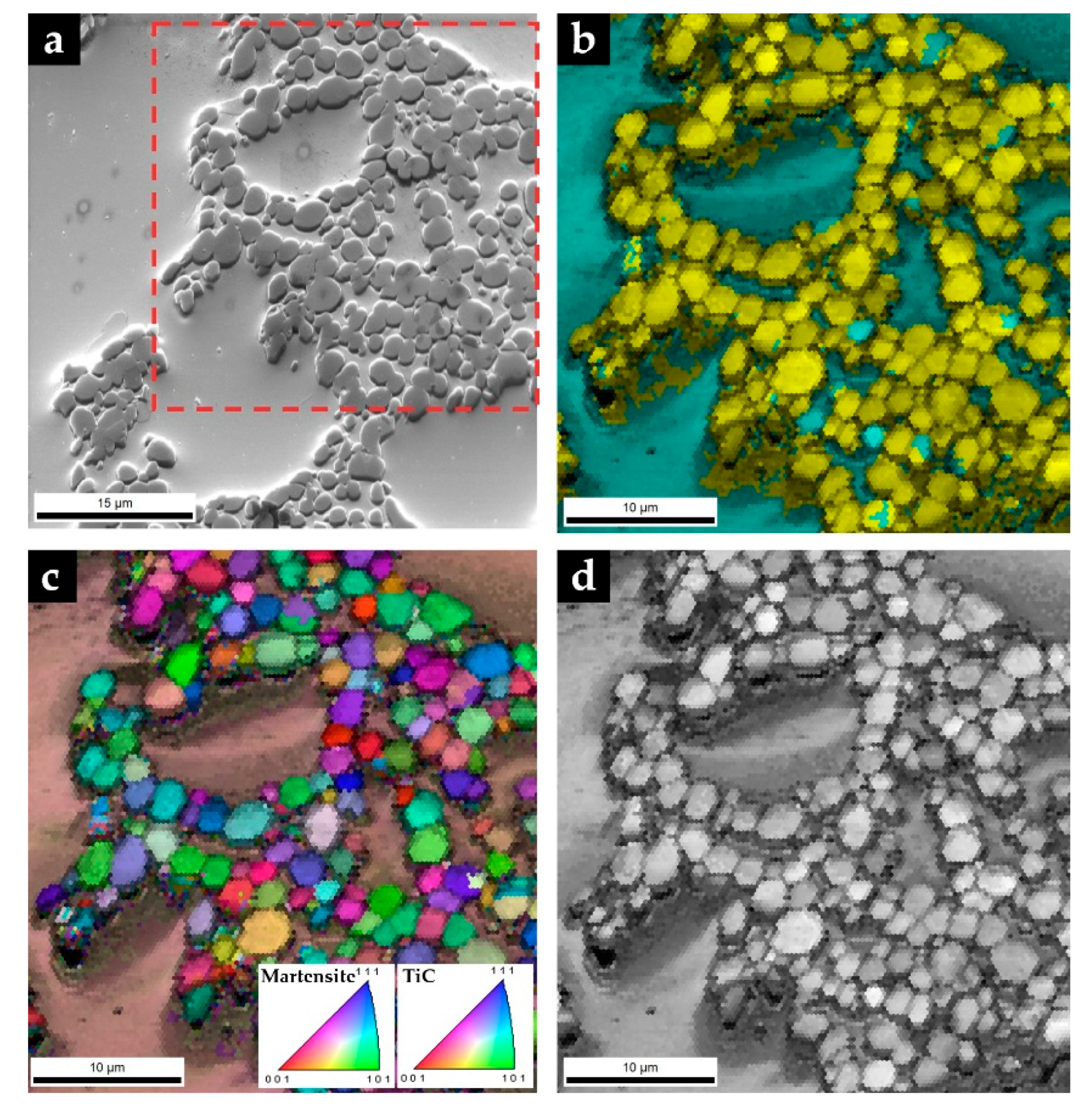
Figure 6.
SEM-BSE image of the CZ with a high amount of agglomerated TiC particles (a); SEM-SE image under typical EBSD experimental conditions (tilted sample) of the analyzed zone (b); indexed EBSD patterns corresponding to the phases present in the composite: TiC (c), κ-carbide (d), and α’ (e).
Figure 6.
SEM-BSE image of the CZ with a high amount of agglomerated TiC particles (a); SEM-SE image under typical EBSD experimental conditions (tilted sample) of the analyzed zone (b); indexed EBSD patterns corresponding to the phases present in the composite: TiC (c), κ-carbide (d), and α’ (e).
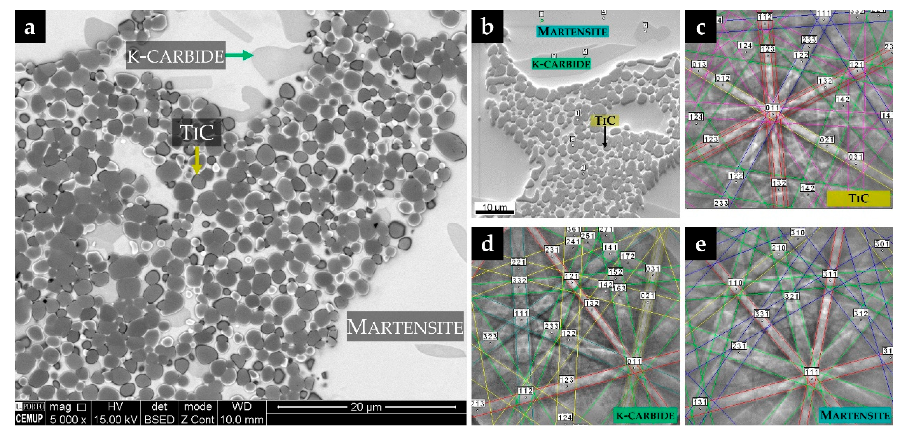
Figure 7.
HAADF-STEM image of the composite showing (a) TiC particles, κ-carbide, and α’ phase. The identification of phases was conducted by selected area electron diffraction (SAED) analysis of TiC, (b) κ-carbide (c), and α’ (d).
Figure 7.
HAADF-STEM image of the composite showing (a) TiC particles, κ-carbide, and α’ phase. The identification of phases was conducted by selected area electron diffraction (SAED) analysis of TiC, (b) κ-carbide (c), and α’ (d).
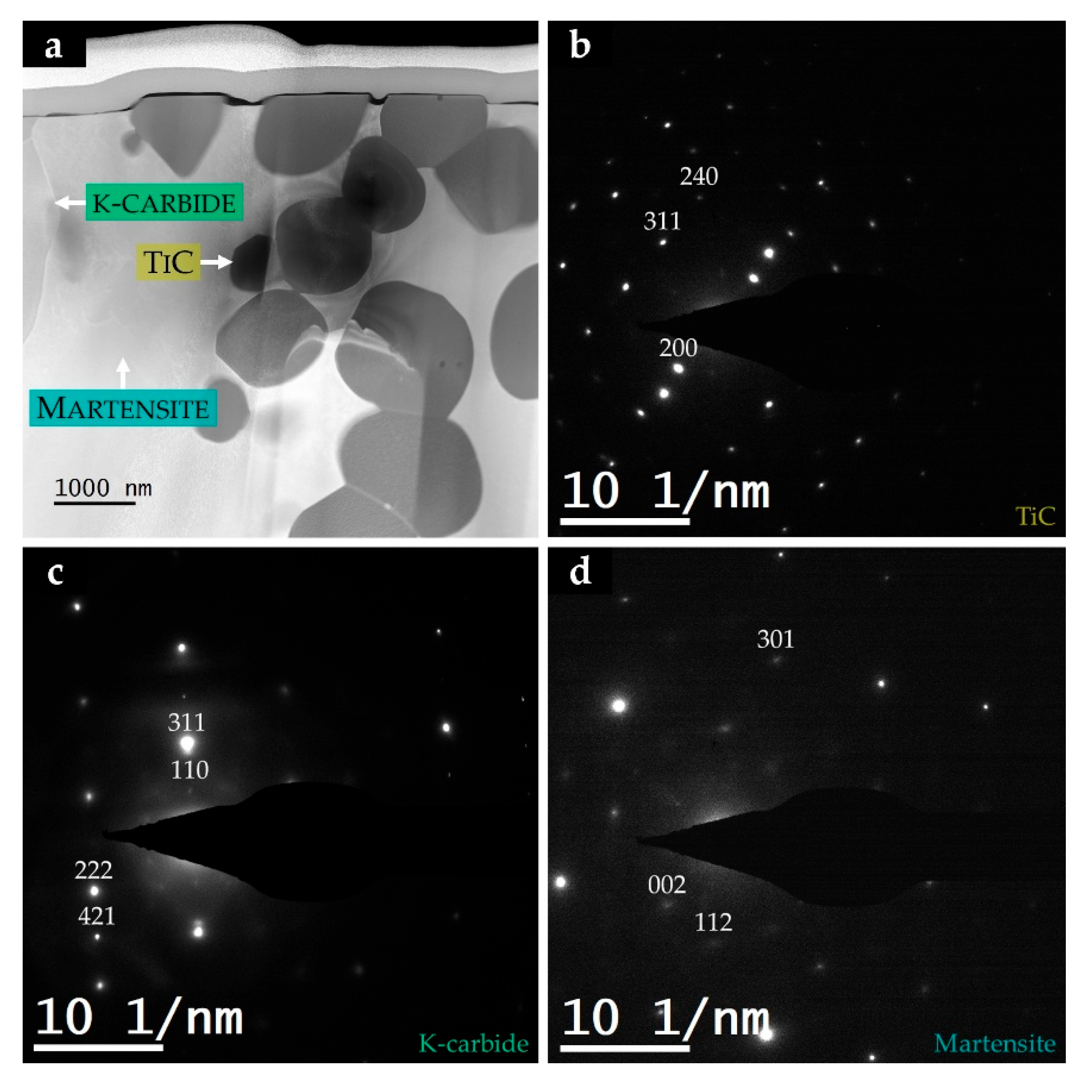
Figure 8.
HAADF-STEM image of the CZ (a) and the STEM-EDS maps of Ti (b), Fe (c), Al (d), and C (e) from the corresponding area.
Figure 8.
HAADF-STEM image of the CZ (a) and the STEM-EDS maps of Ti (b), Fe (c), Al (d), and C (e) from the corresponding area.
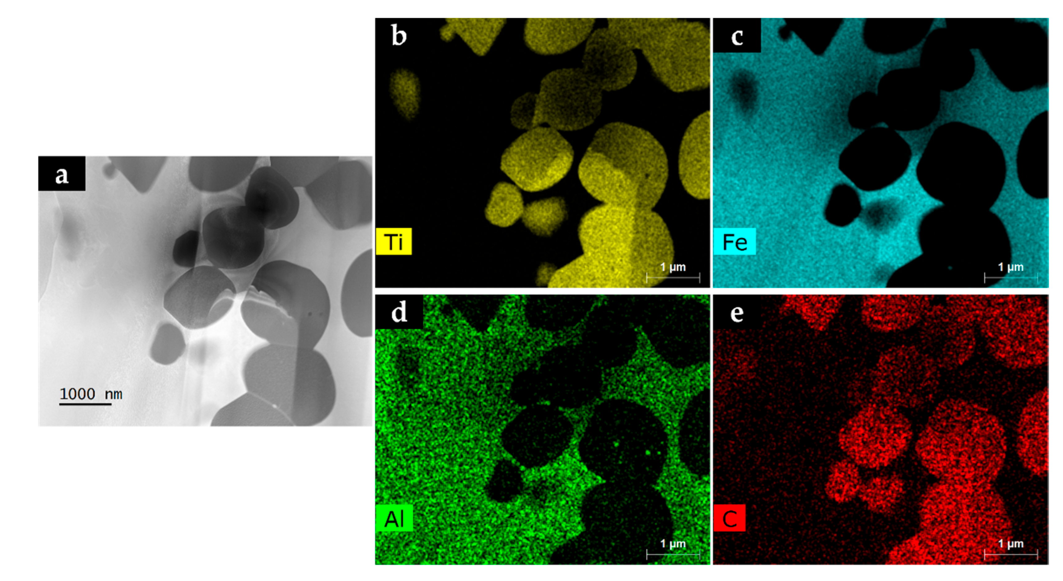
Figure 9.
Particle size distribution of the TiC in the CZ (two perpendicular diameters were measured in 350 particles).
Figure 9.
Particle size distribution of the TiC in the CZ (two perpendicular diameters were measured in 350 particles).
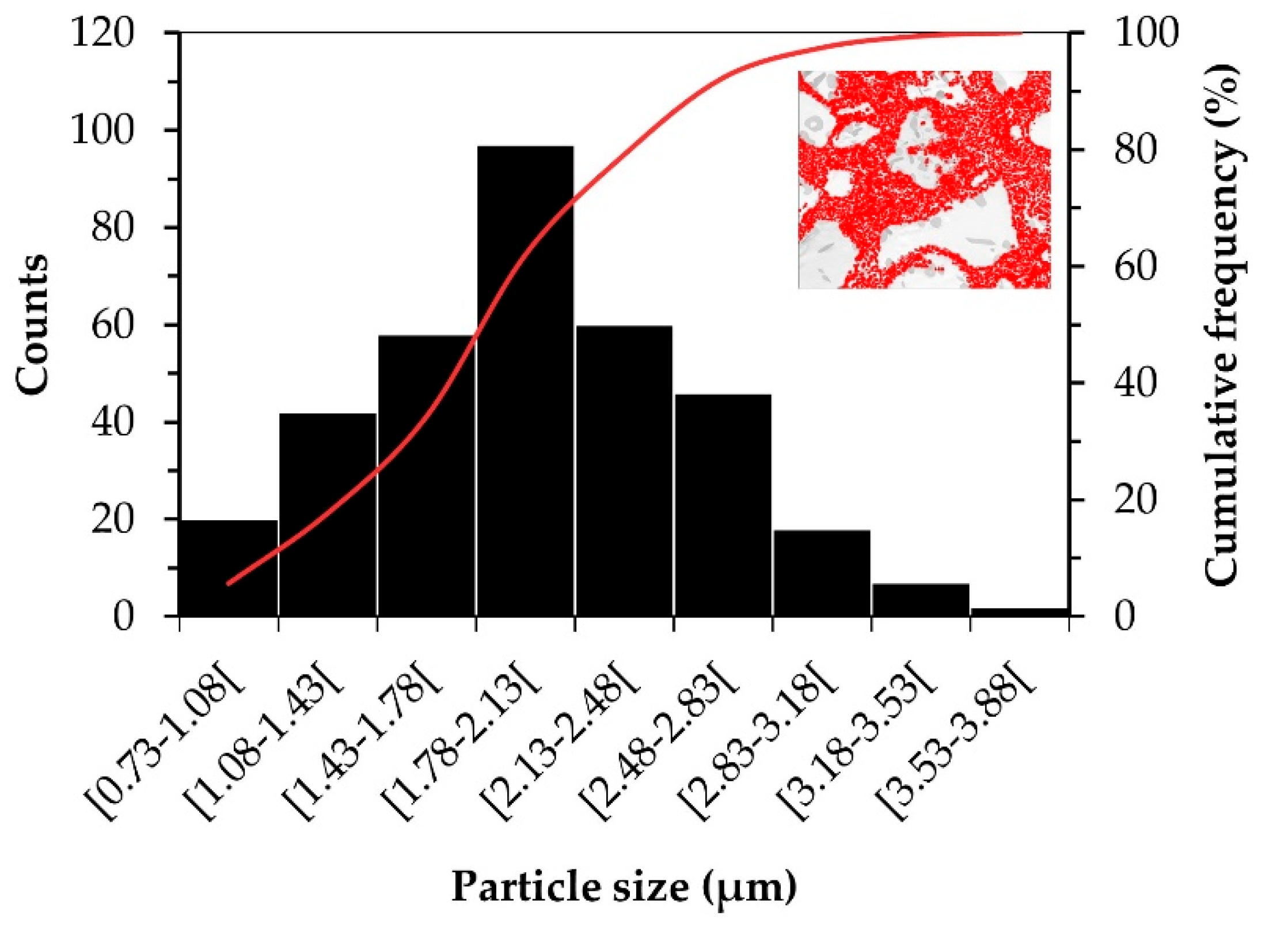
Figure 10.
SEM-BSE image of the microstructure of the interface CZ/BM (a); Comparison of the hardness (HV 30) between the CZ (TiC-steel) and the BM.
Figure 10.
SEM-BSE image of the microstructure of the interface CZ/BM (a); Comparison of the hardness (HV 30) between the CZ (TiC-steel) and the BM.
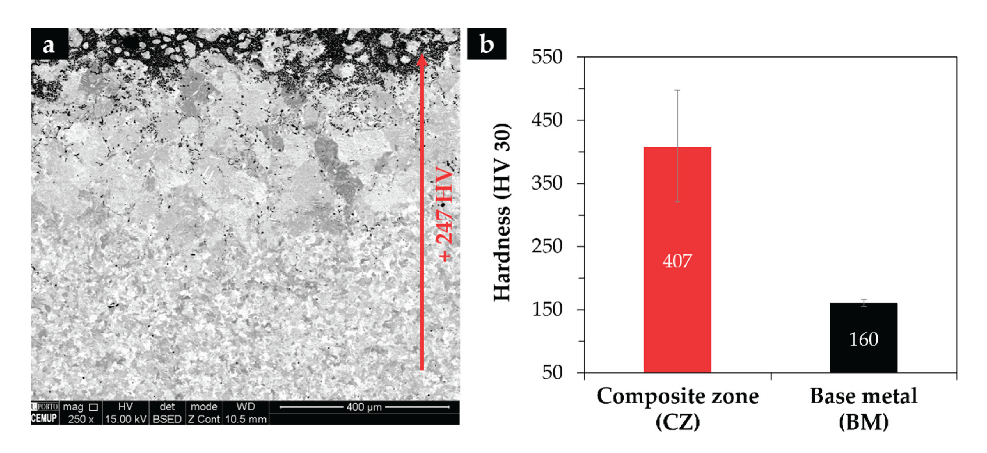
Figure 11.
SEM-BSE image with ETD detector, showing the nanoindentation matrix in the CZ: (b,c) indentations in the α’ matrix and (d,e) in the TiC particles.
Figure 11.
SEM-BSE image with ETD detector, showing the nanoindentation matrix in the CZ: (b,c) indentations in the α’ matrix and (d,e) in the TiC particles.
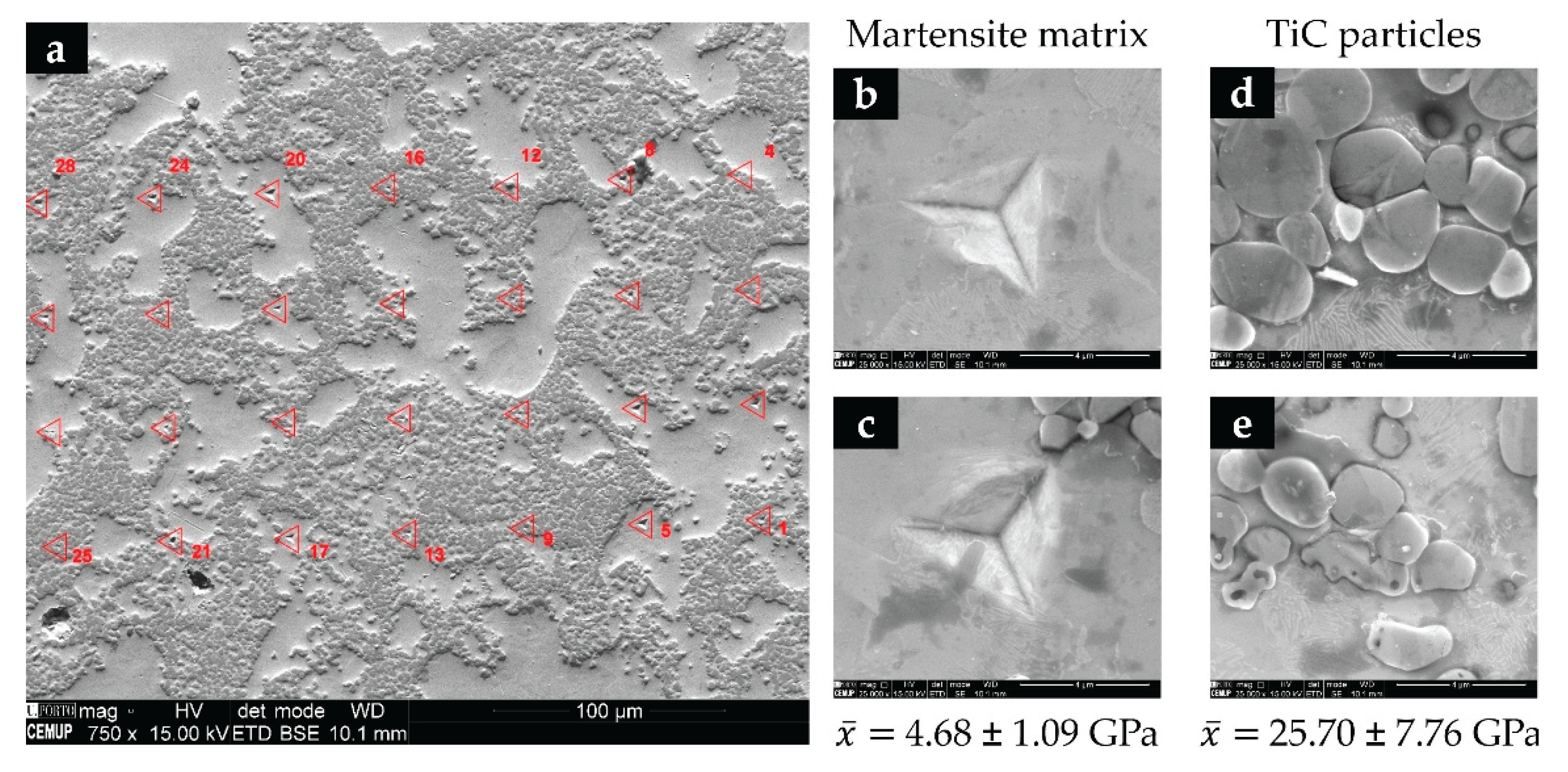
Figure 12.
OM images of the worn craters corresponding to a sliding distance of 31.4 m (a); volume of worn material as a function of the sliding distance under a constant load of 0.25 N for the CZ TiC-Steel and BM low-carbon steel (b).
Figure 12.
OM images of the worn craters corresponding to a sliding distance of 31.4 m (a); volume of worn material as a function of the sliding distance under a constant load of 0.25 N for the CZ TiC-Steel and BM low-carbon steel (b).
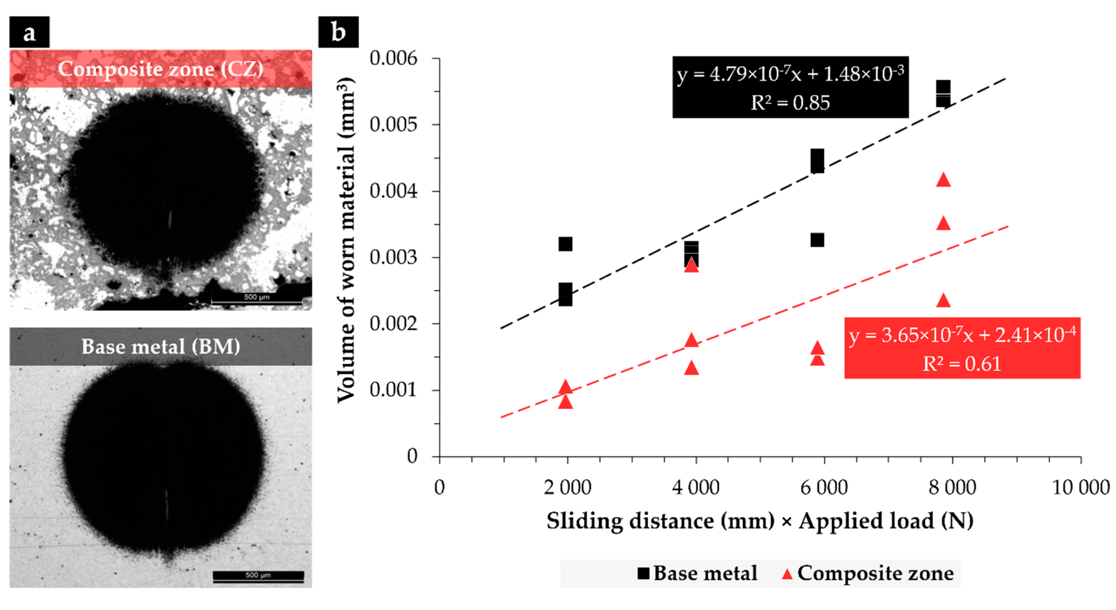
Figure 13.
SEM images of the wear craters after a sliding distance of 31.4 m: (a,b) the CZ, (c,d) BM; (a,b) are regions close to the edge of the crater, and (b,d) are regions of the surface of the crater.
Figure 13.
SEM images of the wear craters after a sliding distance of 31.4 m: (a,b) the CZ, (c,d) BM; (a,b) are regions close to the edge of the crater, and (b,d) are regions of the surface of the crater.
Disclaimer/Publisher’s Note: The statements, opinions and data contained in all publications are solely those of the individual author(s) and contributor(s) and not of MDPI and/or the editor(s). MDPI and/or the editor(s) disclaim responsibility for any injury to people or property resulting from any ideas, methods, instructions or products referred to in the content. |
© 2025 by the authors. Licensee MDPI, Basel, Switzerland. This article is an open access article distributed under the terms and conditions of the Creative Commons Attribution (CC BY) license (http://creativecommons.org/licenses/by/4.0/).
Copyright: This open access article is published under a Creative Commons CC BY 4.0 license, which permit the free download, distribution, and reuse, provided that the author and preprint are cited in any reuse.


