
Submitted:
28 July 2025
Posted:
29 July 2025
You are already at the latest version
Abstract
In this study, a WC-Cu composite coating was successfully fabricated on a mild steel substrate using the novel Plasma Transferred Arc (PTA) welding technique. Phase identification was carried out using X-ray diffraction (XRD), while microstructural evolution was analysed through scanning electron microscopy (SEM). The results indicate that WC particles predominantly interacted with Fe from the substrate, leading to the formation of complex carbides, primarily of the M₁₂C type, within the solution matrix. In contrast, Cu was observed to segregate and remain in discrete regions near the top surface of the coating. The M₁₂C carbides precipitated in two distinct morphologies: coarse, faceted dendritic structures forming equiaxed branches, and herringbone-shaped eutectic structures distributed along the α-Fe grain boundaries. The formation and growth of the eutectic M₁₂C phase was strongly influenced by the thermal gradients and solidification dynamics associated with the PTA welding process. This study highlights the potential of PTA welding for producing wear-resistant composite coatings with tailored microstructures through controlled solidification behaviour.
Keywords:
PTA
; Plasma facing materials
; composites
; cladding
; porosity
; carbides
1. Introduction
Wear is a critical factor influencing the durability and performance of tools and components in demanding industries such as mining, construction, and steel manufacturing [1,2,3]. Since wear resistance is closely linked to the intrinsic properties of the base metal, enhancing these properties has become a significant research focus. One effective strategy involves the fabrication of metal matrix composites (MMCs), where hard ceramic particles are embedded within a softer metallic matrix to improve surface properties [4,5,6]. The wear resistance of such composites depends on several factors, including the size, shape, type, and volume fraction of the reinforcing particles, as well as the bonding strength between the matrix and reinforcement.
Various hard-facing techniques—such as thermal spraying, coating, and welding—have been utilized to introduce these hard particles onto the surface of base materials [7,8,9]. In applications where both wear resistance and electrical conductivity are required, WC-Cu composites serve as promising candidates, particularly in high-voltage electrical circuits, sliding electric contacts, brake pads and electronic circuit board switches [10,11,12]. Meanwhile, Fe-based substrates are commonly used for current transfer applications such as rail connections [13,14]. In these systems, WC enhances resistance against abrasion, impact, and thermal cycling, while the Cu–Fe interface facilitates efficient electrical and thermal conduction. Additionally, the combined presence of Fe and Cu in the matrix enhances toughness by absorbing deformation energy and impeding crack propagation [15]. Depending upon the amount, size, and morphology of the wear resistance WC particles, the properties can be tailored to have better conductivity, wear resistance, and mechanical properties in the fabricated composite [16,17,18].
The effectiveness of an MMC is governed by the homogeneity of particle distribution, phase formation, interfacial bonding, and elemental dilution. These microstructural attributes directly influence macroscopic properties such as wear resistance, hardness, strength, and thermal performance [19,20,21].
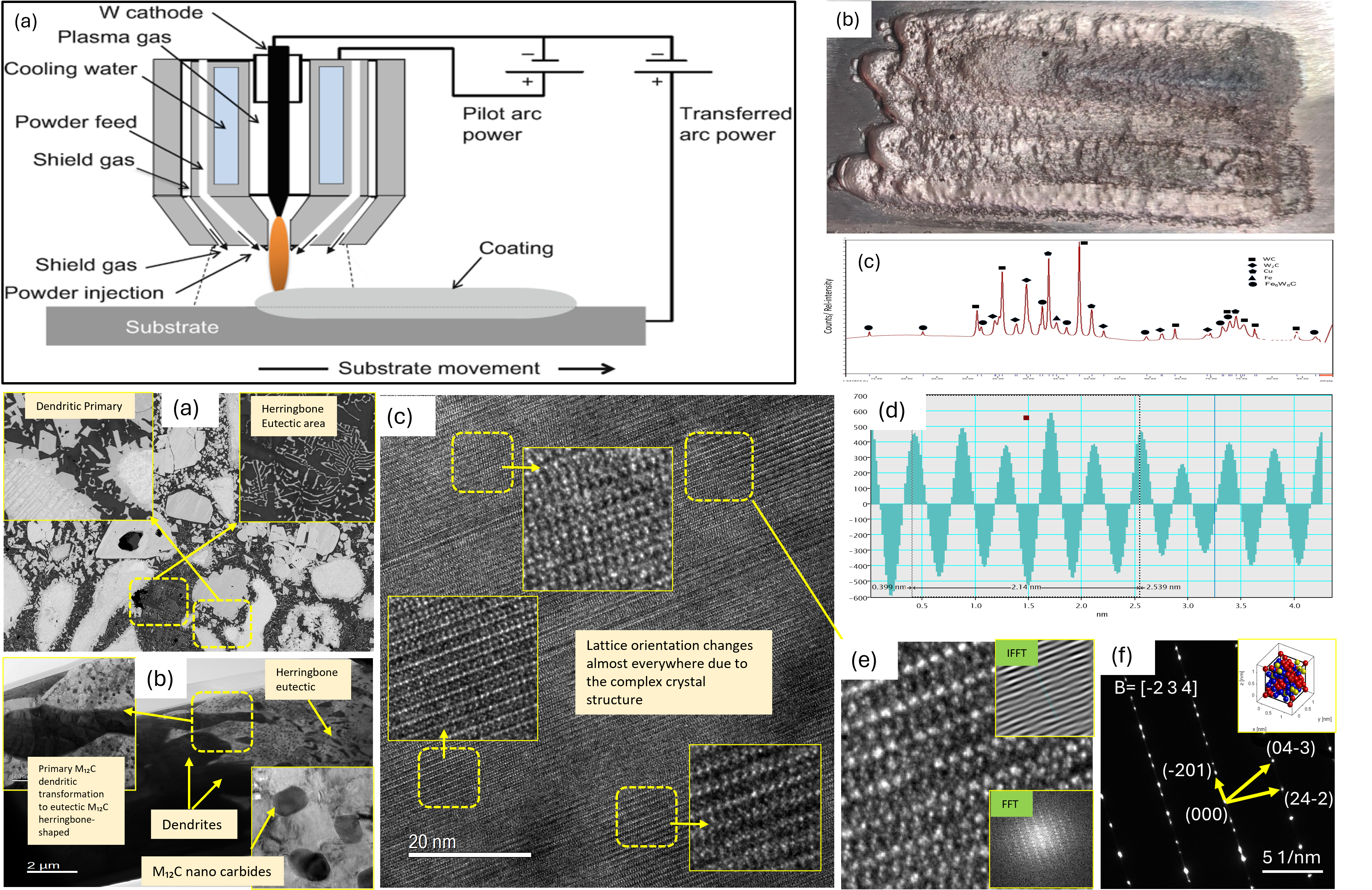
Plasma Transferred Arc (PTA) welding is a promising hard-facing technique capable of depositing wear-resistant materials in powder form onto metallic substrates [5,6,22]. It offers numerous advantages, including low cost, high speed, low dilution, precise control overheat input, compatibility with various powder types, and suitability for repair and bulk coating applications [23,24,25]. Among these, control over dilution and interfacial quality is especially crucial, as they significantly impact the coating’s mechanical integrity and conductivity.
In the present study, an attempt to fabricate and optimize the processing parameters for PTA-based hard-facing and composite fabrication. Certain input parameters were kept constant, while others were systematically varied based on preliminary trials. This research emphasizes composite layer development and sets the foundation for future study. To the best of our knowledge, this specific approach to WC-Cu composite fabrication via PTA on iron-based substrate has not been previously reported.
2. Materials and Experimental Procedure
The WC and Cu powders used in this study were procured from Beijing Ryubon New Material Technology Co. Ltd., China. As shown in Figure 1, the WC powder exhibited a coarse morphology with particle sizes ranging from 100 to 450 µm, while the Cu powder appeared predominantly spherical, with particle sizes in the range of 50 to 200 µm. X-ray diffraction (XRD) analysis confirmed the presence of WC, Cu, and small amount of W particles. The presence of W particles could be due to the non-conversion of W into WC during carburization of W particles. High magnification SEM images revealed that some WC particles were agglomerates of finer WC particles, resulting in a porous morphology. A small number of such agglomerated WC particles were observed.
The powders were mixed in a weight ratio of 70% WC to 30% Cu using a double inversion mixer for 2 hours to ensure uniform blending. The mixed powder was then preheated in a furnace at 110 °C to eliminate moisture before deposition.
Coating deposition was carried out using a Plasma Transferred Arc (PTA) welding system, powered by a Lincoln Aspect 300 machine equipped with a separate control unit for pilot arc triggering, arc transfer, powder feeding, carrier gas flow regulation, and torch coolant circulation. Prior to formal experimentation, a series of trial runs were conducted to optimize the processing parameters required to obtain a uniform and minimal defect bead on a mild steel substrate. Deposition was performed at room temperature and the inter pass temperature was maintained at 80 °C to allow sufficient cooling before starting the next deposition. The optimized parameters were then used to deposit a single layer of the WC-Cu composite coating, as summarized in Table 1.
3. Characterization
Specimens for characterization were extracted from the coated layer using Wire Electrical Discharge Machining (Wire EDM) to ensure precision and minimal thermal damage. For metallographic preparation, standard polishing procedures were followed according to ASTM E3, and final polishing was performed using colloidal silica, which also acted as a mild etchant to reveal microstructural features.
Optical microscopy was conducted using a Nikon Eclipse LV100NDA optical microscope to examine the macrostructure and surface quality. Pore size analysis was performed using ImageJ software, which enabled quantitative image analysis from the captured micrographs.
Scanning Electron Microscopy (SEM) analysis was carried out according to ASTM E1508 using two instruments: the Phenom XL desktop SEM and the JEOL JSM-6490LV high-resolution SEM, to investigate the morphology, phase identification particle distribution, and microstructural evolution of the coatings. For phase identification, X-ray diffraction (XRD) analysis was performed using a GBC MMA X-ray Diffractometer according to ASTM-E3294-22. HighScore Plus software was used for phase analysis, and Rietveld refinement was conducted to obtain quantitative phase composition and lattice parameters from the XRD patterns.
For nanoscale characterization, a focused ion beam (FIB) lamella was prepared using an FEI Helios NanoLab G3 CX system for Transmission Electron Microscopy (TEM) analysis.
TEM imaging and selected area electron diffraction (SAED) patterns were obtained using a JEOL JEM-F200 microscope. Diffraction pattern analysis was carried out using Digital Micrograph (Gatan) and CrystBoxGUI software to identify crystal structures and interpret diffraction data.
4. Results
4.1. Deposition of Beads
Figure 2 illustrates the surface morphology of the beads deposited in a single pass using the processing parameters listed in Table 1. The experiments were conducted at ambient temperature. Visual inspection and microscopic analysis revealed that the deposited beads were free from surface porosity or macroscopic defects, indicating stable processing conditions.
The effect of heat input was found to be critical in achieving optimal deposition quality. Higher heat input levels resulted in the migration of Cu toward the top surface of the bead, and in some cases, partial evaporation of Cu was observed. Conversely, reducing the heat input significantly limited the fusion of WC particles with the substrate, leading to weak bonding and poor metallurgical integration.
The parameters outlined in Table 1 were established as the optimal conditions for the specified particle size range of WC and Cu powders. These conditions enabled a balanced thermal profile that ensured sufficient melting of the matrix material (Cu) while promoting effective anchoring and partial dissolution of WC particles into the Fe-rich substrate without excessive dilution or elemental loss.
Using optimized parameters (Table 1), defect-free W–Cu beads were deposited at ambient temperature (Figure 2), where controlled heat input proved critical—excessive heat caused Cu migration and evaporation, while insufficient heat led to poor WC fusion—ultimately enabling effective Cu melting, partial WC dissolution, and strong metallurgical bonding without excessive dilution.
4.2. Microstructural Characteristics of WC–Cu Deposition
The microstructure of the WC–Cu composite cladding deposited on a mild steel substrate was systematically characterized at various depths within the clad layer, as illustrated in Figure 3. Scanning Electron Microscopy (SEM) revealed a heterogeneous microstructure comprising white, angular particles embedded in a matrix of α-Fe, Cu, and intermetallic carbides. The bright contrast in the SEM images corresponds to tungsten-rich phases (WC and W₂C), while darker grey areas represent the softer Cu and Fe matrix.
The WC particles, introduced in their original form via powder feedstock, were found primarily near the fusion line due to their high density relative to Cu. This preferential segregation is consistent with observations in similar systems. The interaction of WC with Fe from the substrate at elevated temperatures during the Plasma Transferred Arc (PTA) process led to partial dissolution and the formation of reaction products, primarily the M₁₂C carbide phase. These carbides manifested in two distinct morphologies: (i) primary M₁₂C, forming as coarse, equiaxed dendritic structures around the periphery of WC particles, and (ii) eutectic M₁₂C, forming as fine herringbone-shaped lamellae along the grain boundaries of α-Fe. The morphology and distribution of these carbides are influenced by local thermal gradients and repeated heating/cooling cycles induced by the PTA arc.
No pores were detected in the eutectic M₁₂C region while pores in the primary M₁₂C phase were more compared to the top Cu rich area as shown in the Figure 3(a).
X-ray Diffraction (XRD) analysis, performed on a sample cut from the middle of the composite with a Si specimen holder and a Ni filter to suppress Fe fluorescence, confirmed the presence of WC, W₂C, Cu, and M₁₂C (W6Fe6C) phases in the composite (Figure 4). No additional oxide or secondary carbide phases were detected at the top surface. The limited presence of W₂C indicates that only a small fraction of WC underwent decarburization, which is likely inhibited by the rapid cooling facilitated by the high thermal conductivity of Cu. This suggests that most WC particles retained their stoichiometry during deposition.
The observed M₁₂C phase is thermodynamically favoured in low-carbon environments due to its lower formation energy compared to other carbide types like M6C or MC. Moreover, M₁₂C exhibits a more stable lattice with fewer atoms per unit cell (8 for M₁₂C vs. 16 for M6C), supporting its preferential formation in the present system [26]. The presence of herringbone eutectic M₁₂C was especially prominent near the fusion line, where heat accumulation promotes eutectic transformation, whereas in the mid-cladding regions, M₁₂C primarily exists as discrete dendritic structures [27].
Rietveld refinement of the XRD data was performed using HighScore Plus software with reference structures from the PDF-5 database. The refined lattice parameters, summarized in Table 2, show minor deviations from standard values for WC and W₂C. W₂C has been reported to be stable at room temperature [28]. These discrepancies are attributed to lattice distortion caused by rapid thermal cycles and possible substitutional dissolution of Fe in the tungsten carbide matrix during solidification. The ternary carbide M₁₂C exhibited good agreement with standard crystallographic data, suggesting a stable intermetallic structure. The presence of strong single peak at 44.28° shows the presence of preferred single structure [29]. However, due to the presence of Fe acting as radiation absorber can also lead to minimize the overall intensity of the peaks [30].
Figure 5.
(a) illustrates M₁₂C morphologies coexisting, while (b) shows extensive transformation of dendritic M₁₂C into herringbone structures under increased thermal cycling.
Figure 5.
(a) illustrates M₁₂C morphologies coexisting, while (b) shows extensive transformation of dendritic M₁₂C into herringbone structures under increased thermal cycling.
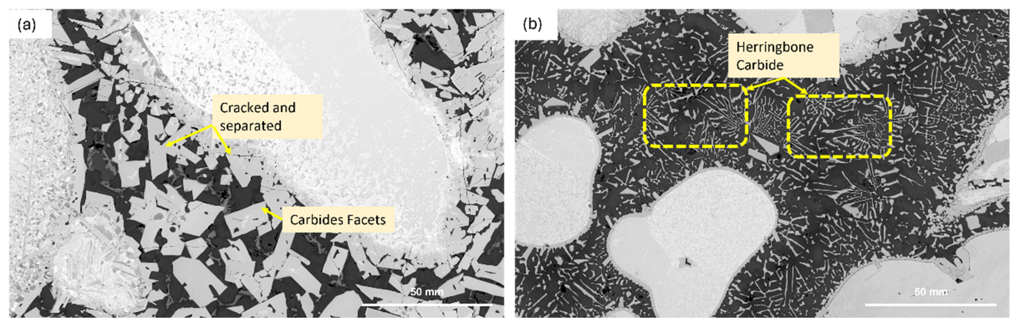
Figure 1: Conversion from facets to herringbone shape M6C carbides.
The transformation from WC to W₂C is believed to occur via a decarburization reaction during deposition, as described by the equation [31]:
2WC → W₂C + C
The selective etching using a solution of OP-S and NH₃/H₂O₂, provided further contrast between WC and W₂C phases. As shown in Figure 6, W₂C appears as distinct dark features in the backscattered electron (BSEM) images, confirming that this etching technique selectively reveals W₂C due to its different electrochemical properties [32].
The WC–Cu composite cladding on mild steel revealed a heterogeneous microstructure with WC and W₂C phases concentrated near the fusion line and embedded in an α-Fe/Cu matrix, where partial WC dissolution during PTA processing led to the formation of thermodynamically stable M₁₂C carbides—appearing as both coarse dendrites and fine eutectic herringbone structures—whose identities and distributions were confirmed through SEM, XRD (with Rietveld refinement), EDS, and selective etching, indicating limited WC decarburization, Fe substitution effects, and microstructural evolution driven by thermal cycling.
4.3. Elemental Distribution and EDS Analysis
Energy-Dispersive X-ray Spectroscopy (EDS) analysis was conducted at three distinct regions within the WC–Cu composite coating, as illustrated in Figure 7. The results reveal an inhomogeneous distribution of Cu, α-Fe, and WC/W₂C particles within the matrix, reflecting the complex thermal and fluid dynamics during deposition.
Near the top surface, WC/W₂C particles are predominantly surrounded by the Cu-rich phase. This region exhibits the highest porosity, localized mainly within the Cu matrix, which is consistent with its lower melting point and potential for gas entrapment during solidification. Although the WC/W₂C particles are relatively homogeneously dispersed in this zone, the overall particle density is lower than that observed in the middle region. Furthermore, no significant carbide precipitation was detected near the surface, indicating limited interaction between the phases under the rapid cooling conditions at this interface.
The middle region marks a transitional zone characterized by a rapid change in matrix composition from Cu to α-Fe. Here, the formation of M₁₂C carbides is more pronounced, occurring as discrete precipitates within the matrix. This suggests an increased interaction between W and Fe at intermediate depths, influenced by the thermal gradients and diffusion kinetics. Near the fusion line, a narrow Cu-rich band is observed enveloping the WC/W₂C and α-Fe matrix. The intensity of carbide precipitation increases with distance from this Cu band, indicating the strong influence of Cu’s high thermal conductivity in moderating the microstructural evolution. The central region of the matrix exhibits the highest carbide density, highlighting the thermal buffering effect of Cu in the adjacent zones.
The distribution of elements is further influenced by fluid flow dynamics in the molten weld pool. The density-driven buoyancy forces and Marangoni convection collectively govern the segregation behaviour of Fe, W, and Cu during solidification. The relatively high density of W particles causes them to settle near the bottom of the weld pool, while buoyancy forces drive Fe and Cu towards the upper regions. However, Fe preferentially nucleates at WC particle surfaces, stabilizing its presence near WC-rich areas, whereas Cu solidifies predominantly along the outer boundaries of the weld bead. At elevated temperatures, gravity forces dominate over Marangoni effects as the surface tension of molten Cu decreases, facilitating the floating of Cu over Fe and the retention of WC particles near the penetration depth. Additionally, high heat inputs promote partial Cu evaporation at the bead surface.
Quantitative spot EDS analysis from Figure 8a in Table 3 confirms the weight percentages of the carbide phases in agreement with the predicted ranges from phase diagrams [33].The analysis also indicates that only a minor fraction of the original WC particles remains unreacted, with the majority undergoing partial or complete melting and subsequent transformation during deposition. Furthermore, the map EDS analysis shown in the Figure 8b,c,d,e confirms the relative concentration of Fe atoms into the carbide facets compared with those present as α-Fe.
Considering the Fe–Cu binary phase diagram, the solubility of iron in copper is effectively zero at room temperature. Consequently, liquid-liquid phase separation is a critical phenomenon during solidification, which is reflected in the microstructure exhibiting both dendritic and spheroidal morphologies, as shown in Figure 9 [34]. The extent of segregation and miscibility within the Cu–Fe system can be quantitatively described by the composition-composition structure factor, Scc (0), derived from the Gibbs free energy of mixing. The positive Scc(0) values at elevated temperatures indicate a thermodynamic preference for like-atom clustering, leading to segregation into distinct dendritic and spheroidal phases [35].
At the solidification front of the base metal, a thin molten layer predominantly composed of ferrite forms, serving as an interface between the parent grains and the newly solidified Cu–Fe solid solution. This layer plays a pivotal role in the bonding and microstructural evolution at the coating-substrate interface.
Microstructural analysis reveals a predominance of dendritic iron growth over spheroidal transformation, with only primary dendrites forming due to supercooling effects during solidification. Additionally, grain boundary diffusion of Cu into the base metal has been observed, which may influence interfacial properties and overall coating adhesion.
EDS analysis across the WC–Cu composite cladding revealed depth-dependent inhomogeneity—where surface regions showed Cu-rich matrices with high porosity and limited carbide formation, the midsection exhibited significant M₁₂C carbide precipitation due to enhanced W–Fe interaction, and near the fusion line, Cu’s high thermal conductivity and fluid flow dynamics shaped elemental segregation—with Fe nucleating near WC particles and Cu segregating outward, all governed by buoyancy, Marangoni effects, and solidification thermodynamics, while spot EDS and phase diagram comparisons confirmed partial WC transformation and dendritic iron growth driven by phase separation and grain boundary diffusion.
4.4. TEM Analysis
To validate the crystal structure of the intermetallic phase formed during cladding, Transmission Electron Microscopy (TEM) diffraction analysis was conducted. Selected Area Electron Diffraction (SAED) patterns were obtained and compared with simulated patterns derived from Crystallographic Information Files (CIF), specifically for the Fe₆W₆C phase. The experimental diffraction pattern showed a strong match with the theoretical diffraction, confirming the presence of Fe₆W₆C as a dominant intermetallic phase in the matrix.
High-resolution TEM (HRTEM) imaging revealed a complex and continuous lattice structure, as shown in Figure 10. The structure appears variable due to overlapping atomic planes and the high density of lattice defects. The measured interplanar spacing (d-spacing) for two crystallographic planes—identified as (1.22 0.41 0)—was approximately 0.856 nm. It is important to note that this value corresponds to the apparent doubling of atomic planes observed in the HRTEM image, where alternating rows of atoms are more prominently resolved, leading to a doubled periodicity.
The inverse fast Fourier transform (IFFT) image derived from the HRTEM data further corroborates the structural complexity. The IFFT pattern displays significant lattice distortion, indicating a high atomic packing density and the presence of dislocations within the unit cell. These distortions suggest substantial internal strain in the Fe₆W₆C phase, possibly due to thermal stresses and rapid solidification during the PTA process.
Transmission Electron Microscopy (TEM) and diffraction analysis confirmed the formation of Fe₆W₆C as the dominant intermetallic phase in the WC–Cu composite, with high-resolution TEM revealing complex lattice structures, dislocations, and internal strain—evidenced by doubled interplanar spacing and limited but distorted IFFT patterns—attributed to thermal stress and rapid solidification during PTA processing.
5. Discussion
The high-temperature plasma transferred arc (PTA) process induces complex metallurgical and thermodynamic phenomena during the deposition of the WC–Cu composite onto a mild steel substrate. The localized melting of both the copper matrix and the iron from the base metal facilitates mutual dissolution and migration, primarily governed by the thermodynamic forces acting on the weld pool. These include Lorentz forces, buoyancy-driven flow, surface tension gradients (Marangoni effects), and arc impingement.
Due to its high melting point, WC remains largely unmelted and is suspended within the molten Cu–Fe matrix. The molten Fe and Cu migrate through lattice diffusion, grain boundary diffusion, or penetrate the base metal via capillary-driven mechanisms. Lattice diffusion involves atom migration into interstitial or substitutional sites, while grain boundary diffusion and penetration allow for faster transport paths due to the lower energy barriers at grain interfaces. This set of mechanisms—especially the migration through boundaries and subsequent absorption into grains—can be broadly described as the irrigation effect of Cu into the base metal.
Once migration occurs, recrystallization is driven by rapid cooling. For dissimilar metal systems such as Cu–Fe, which exhibit immiscibility and zero solid solubility at room temperature, liquid–liquid separation is expected. The resulting microstructure reflects this behaviour, with Cu and Fe segregating into distinct phases during solidification. Dendritic and spheroidal morphologies observed in Fe domains support this, consistent with the positive composition–composition structure factor, Scc(0) indicating preferential segregation of like atoms.
During high-temperature PTA deposition, complex thermodynamic forces—including Lorentz forces, buoyancy, Marangoni effects, and arc impingement—govern the migration and mutual dissolution of molten Cu and Fe into the WC–Cu composite, while WC remains largely unmelted, and subsequent lattice and grain boundary diffusion (irrigation effect) followed by rapid cooling induces recrystallization and liquid–liquid phase separation, producing distinct Cu and Fe segregation with dendritic and spheroidal Fe morphologies along with M₁₂C.
6. Microstructural Interpretation
Microstructural analysis reveals that WC particles are concentrated near the fusion line, separated from the bulk matrix by a narrow Cu-rich band. This distribution is due to the combined influence of density differences (WC > Cu, Fe), high thermal conductivity of Cu, and selective wetting behaviour. The thin Cu layer near the fusion line indicates moderate mixing conditions under optimized PTA parameters.
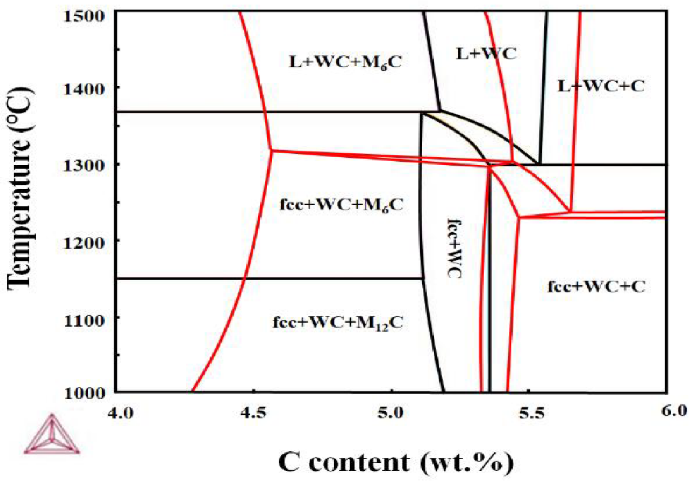
From thermodynamic phase analysis as shown in figure 11, M₁₂C type eutectic carbides are favoured under carbon concentrations ranging from 5 to 5.4 wt.%, particularly in mild steels containing 0.05–0.25 wt.% C [33]. Despite M₁₂C having a higher number of carbon atoms per unit cell (16 vs. 8 in M₁₂C), M₁₂C formation is thermodynamically favourable in this system. The observed dendritic growth near the fusion line is a result of constitutional undercooling, which occurs when the temperature gradient to solidification front velocity ratio (G/R) becomes negative. This leads to the formation of both primary and secondary dendrites, forming characteristic "fishbone-like" M₁₂C morphologies in regions of rapid solidification.
Figure 11.
WC transformation into M6C and M12C.
Larger WC particles, only partially melted, act as heterogeneous nucleation sites, whereas smaller ones decompose and dissolve. Cladding with 30% overlap results in more pronounced fishbone carbide formation than single pass deposits due to remelting and prolonged growth time for carbides during successive passes.
7. Porosity Formation Mechanisms
Rounded porosities predominantly in the Cu phase were observed and attributed to:
- (a)
- Entrapment of argon carrier gas in the molten pool,
- (b)
- Boiling of Cu due to elevated arc temperatures,
- (c)
- Inhibition of heat flow by W’s low thermal diffusivity,
- (d)
- Plasma entrapment in molten Cu from keyhole effects around falling W particles.
To investigate these mechanisms, experiments were conducted by varying the interpass temperature (150°C, 200°C, 300°C). Results show a decrease in subsurface porosity and increased surface-reaching bubbles at higher temperatures, indicating enhanced gas escape. However, excessive heating also induced fine porosity due to Cu vaporization.
Additionally, plasma entrapment was examined by modifying powder feed orientation and carrier gas flow. When the torch was rotated by 90°, allowing gravity-driven powder feeding without carrier gas injection, no porosity was detected. This supports the hypothesis that plasma and argon entrapment are significant contributors to gas pore formation.
Lowering carrier gas flow minimized turbulence in the plasma zone, leading to reduced porosity. Despite these adjustments, SEM imaging of pores revealed internal cracking and ripple-like morphologies, indicative of high thermal gradients and localized overheating. These features suggest that inside the pores, temperatures likely exceeded the boiling point of Cu, and subsequent rapid solidification caused contraction-induced microcracking within the Cu phase.
8. Conclusions
The WC and Cu was successfully deposited on mild steel substrate with microstructure composed of α-Fe, Cu, W2C, WC, and intermetallic phase M12C were confirmed in the microstructure using XRD, EDS, and TEM diffraction analysis. The heat input controlled by proper selection of the PTA parameters has a great effect on the microstructure evolution, homogeneity, and porosity of the deposit. Simultaneous migration and dissolution from the base metal occurs into the molten pool causing reactions at elevated temperature and formation of intermetallic phase M12C confirmed by XRD and TEM analysis. Grain boundary penetration of Cu into the base metal has caused an irrigation effect. The amount and size of the WC particles has a great effect on the formation of intermetallic brittle phase M12C. No pores or cracks were observed in the carbide herringbone shaped region indicating that the herringbone structure could have more advantages in terms of mechanical properties than the facet carbides.
Future recommendations:
Future work may explore the use of finer WC particles and the exclusive formation of herringbone-shaped carbides to develop pore-free microstructures with enhanced mechanical performance. Such configurations could leverage solid solution strengthening mechanisms to improve overall strength while minimizing brittleness. Additionally, optimizing the Cu content offers a promising route to tailor thermal and electrical conductivity, warranting a comprehensive investigation into its compositional effects. The Cu-rich layer near the fusion line not only contributes to improved conductive properties between Cu and Fe but may also act as a shock-absorbing buffer, potentially enhancing durability in applications such as electrical contacts by accommodating deformation prior to failure.
Author Contributions
M.H., conceptualization, methodology, investigation, data analysis, and writing and editing—original draft; B.D., resources, data validation, data curation, methodology, review, and editing; Z.Q., external supervision, review and editing, project administration, external funding acquisition, and resources; U.G., project administration, resources, visualization, external funding acquisition, external supervision, and resources; Z.P., conceptualization, investigation, supervision, and project administration; H.L., conceptualization, investigation, supervision, and project administration. All authors have read and agreed to the published version of the manuscript.
Funding
This study was supported by the Australian Nuclear Science and Technology Organization–University of Wollongong Joint Project Seed Funding.
Conflicts of Interest
The authors declare that they have no known competing financial interests or personal relationships that could have appeared to influence the study reported in this paper.
Abbreviations
| PTA | Plasma Transferred Arc |
| MMCs | Metal Matrix Composites |
| XRD | X-ray Diffraction |
| SEM | Scanning Electron Microscopy |
| EDM | Electrical Discharge Machining |
| FIB | Focused Ion Beam |
| TEM | Transmission Electron Microscopy |
| SAED | Selected Area Electron Diffraction |
| M₁₂C | Fe6W6 C |
| M₆C | Fe3W3 C |
| BSEM | Backscattered Electron Microscopy |
| CIF | Crystallographic Information File |
| HRTEM | High-Resolution Transmission Electron Microscopy |
| FFT | Fast Fourier Transform |
| IFFT | Inverse Fast Fourier Transform |
| G/R | Temperature Gradient to Solidification Rate Ratio |
References
- Holmberg, K., et al., Global energy consumption due to friction and wear in the mining industry. Tribology International, 2017. 115: p. 116-139. [CrossRef]
- Buchely, M., et al., The effect of microstructure on abrasive wear of hardfacing alloys. wear, 2005. 259(1-6): p. 52-61. [CrossRef]
- Appiah, A.N.S., et al., Hardfacing of mild steel with wear-resistant Ni-based powders containing tungsten carbide particles using powder plasma transferred arc welding technology. Materials Science-Poland, 2022. 40(3): p. 42-63. [CrossRef]
- Leech, P.W., X.S. Li, and N. Alam, Comparison of abrasive wear of a complex high alloy hardfacing deposit and WC–Ni based metal matrix composite. Wear, 2012. 294: p. 380-386. [CrossRef]
- Prabanjan, S., et al., Wear behavior and metallurgical characteristics of particle reinforced metal matrix composites produced by hardfacing: A review. Materials Today: Proceedings, 2020. 33: p. 599-606. [CrossRef]
- Aoh, J.-N. and J.-C. Chen, On the wear characteristics of cobalt-based hardfacing layer after thermal fatigue and oxidation. Wear, 2001. 250(1): p. 611-620. [CrossRef]
- Mao, L., et al., Effects of spherical WC powders on the erosion behavior of WC-Ni hardfacing used for steel body drill bit. Surface and Coatings Technology, 2021. 409: p. 126893. [CrossRef]
- Pintsuk, G., et al., Fabrication and characterization of vacuum plasma sprayed W/Cu-composites for extreme thermal conditions. Journal of materials science, 2007. 42: p. 30-39. [CrossRef]
- Deng, N., et al., Fabrication and characterization of WCu composite coatings with different W contents by cold spraying. Surface and Coatings Technology, 2019. 368: p. 8-14. [CrossRef]
- Zhou, Y.X., Y.L. Xue, and K. Zhou, Failure analysis of arc ablated tungsten-copper electrical contacts. Vacuum, 2019. 164: p. 390-395. [CrossRef]
- Tungsten-copper for use in circuit breakers. Accessed on 08-05-2024]; Available from: https://www.plansee.com/en/products/wcu-switching-contacts.html.
- Xiao, Y., et al., Mechanical and tribological behaviors of copper metal matrix composites for brake pads used in high-speed trains. Tribology International, 2018. 119: p. 585-592. [CrossRef]
- Wang, Y., et al., Interfacial characterization of T3 copper/35CrMnSi steel dissimilar metal joints by inertia radial friction welding. The International Journal of Advanced Manufacturing Technology, 2013. 68: p. 1479-1490. [CrossRef]
- Zhao, X., et al., Investigation on the Microstructure and Mechanical Properties of Stud Welded Joints of Cu/304 Austenitic Stainless Steel under Different Welding Voltages. Journal of Materials Engineering and Performance, 2023. 32(2): p. 613-623. [CrossRef]
- Bai, H., et al., Microstructure and mechanical properties of W-WC/Fe composite fiber-reinforced Fe matrix composite prepared by combination of infiltration and in-situ solid phase diffusion. Journal of Materials Research and Technology, 2023. 27: p. 5305-5314. [CrossRef]
- Zhao, Z., et al., Investigation on the mechanical properties of WC–Fe–Cu hard alloys. Journal of Alloys and Compounds, 2015. 632: p. 729-734. [CrossRef]
- Shi, H., et al., Influence of pre-alloying on Fe-Cu based metal matrix composite. Journal of Alloys and Compounds, 2021. 868: p. 159134. [CrossRef]
- Zhai, K., et al., Microstructure and properties of WC-CoCuFeNi composites fabricated by spark plasma sintering. International Journal of Refractory Metals and Hard Materials, 2022. 105: p. 105808. [CrossRef]
- Tejado, E., et al., The thermo-mechanical behaviour of W-Cu metal matrix composites for fusion heat sink applications: The influence of the Cu content. Journal of Nuclear Materials, 2018. 498: p. 468-475. [CrossRef]
- Zhang, H., J.-R. Liu, and G.-H. Zhang, Preparation and properties of W-30 wt% Cu alloy with the additions of Ni and Fe elements. Journal of Alloys and Compounds, 2022. 928: p. 167040. [CrossRef]
- Han, T., et al., Simultaneous enhancement of strength and conductivity via self-assembled lamellar architecture. Nature Communications, 2024. 15(1): p. 1863. [CrossRef]
- Balasubramanian, V., et al., Application of Response Surface Methodolody to Prediction of Dilution in Plasma Transferred Arc Hardfacing of Stainless Steel on Carbon Steel. Journal of Iron and Steel Research, International, 2009. 16(1): p. 44-53. [CrossRef]
- Łatka, L. and P. Biskup, Development in PTA surface modifications–a review. Advances in Materials Science, 2020. 20(2): p. 39-53. [CrossRef]
- Takano, E.H., D. de Queiroz, and A.S.C.M. D'Oliveira, Evaluation of processing parameters on PTA hardfacing surfaces. Welding International, 2010. 24(3): p. 241-248. [CrossRef]
- Lakshminarayanan, A.K., et al., Predicting the dilution of plasma transferred arc hardfacing of stellite on carbon steel using response surface methodology. Metals and Materials International, 2008. 14(6): p. 779-789. [CrossRef]
- Suetin, D.V., I.R. Shein, and A.L. Ivanovskii, Structural, electronic and magnetic properties of η carbides (Fe3W3C, Fe6W6C, Co3W3C and Co6W6C) from first principles calculations. Physica B: Condensed Matter, 2009. 404(20): p. 3544-3549. [CrossRef]
- Zhang, J., et al., Porous tungsten synthesized via dealloying: Fe6W6C induced structure modification and mechanical behavior. Journal of Alloys and Compounds, 2023. 947: p. 169708. [CrossRef]
- Luo, N., et al., Toward a Unified Understanding of W2C Polymorphic Structures by First-Principles Calculations. Crystal Growth & Design, 2023. 23(8): p. 5486-5497. [CrossRef]
- Dadashi, S., R. Poursalehi, and H. Delavari, Structural and Optical Properties of Pure Iron and Iron Oxide Nanoparticles Prepared via Pulsed Nd:YAG Laser Ablation in Liquid. Procedia Materials Science, 2015. 11: p. 722-726. [CrossRef]
- Shakunt, N.S., Gouthama, and A. Upadhyaya, Effect of Fe addition in W-Ni-Cu heavy alloy processed through powder metallurgy on microstructure and mechanical properties. Journal of Alloys and Compounds, 2024. 970: p. 172578. [CrossRef]
- Cheniti, B., et al., Investigation of WC decarburization effect on the microstructure and wear behavior of WC-Ni hardfacing under dry and alkaline wet conditions. Materials Chemistry and Physics, 2018. 208: p. 237-247. [CrossRef]
- Mühlbauer, G., et al., Transition of W2C to WC during carburization of tungsten metal powder. International Journal of Refractory Metals and Hard Materials, 2018. 72: p. 141-148. [CrossRef]
- Li, X., et al., Microstructure Evolution and Hardness Improvement of WC-Co Composites Sintered with Fe Substituting Part of Co Binder. Coatings, 2023. 13(1): p. 116. [CrossRef]
- Huang, S., et al., Study on the microstructure evolution and mechanical properties of spray-forming Cu-Fe alloys with varying Fe compositions. Journal of Alloys and Compounds, 2025. 1013: p. 178452. [CrossRef]
- Liu, S., et al., Solidification microstructure evolution and its corresponding mechanism of metastable immiscible Cu80Fe20 alloy with different cooling conditions. Journal of Alloys and Compounds, 2018. 742: p. 99-106. [CrossRef]
Figure 1.
(a) SEM morphology of the WC and Cu, (b) XRD map of the powder.
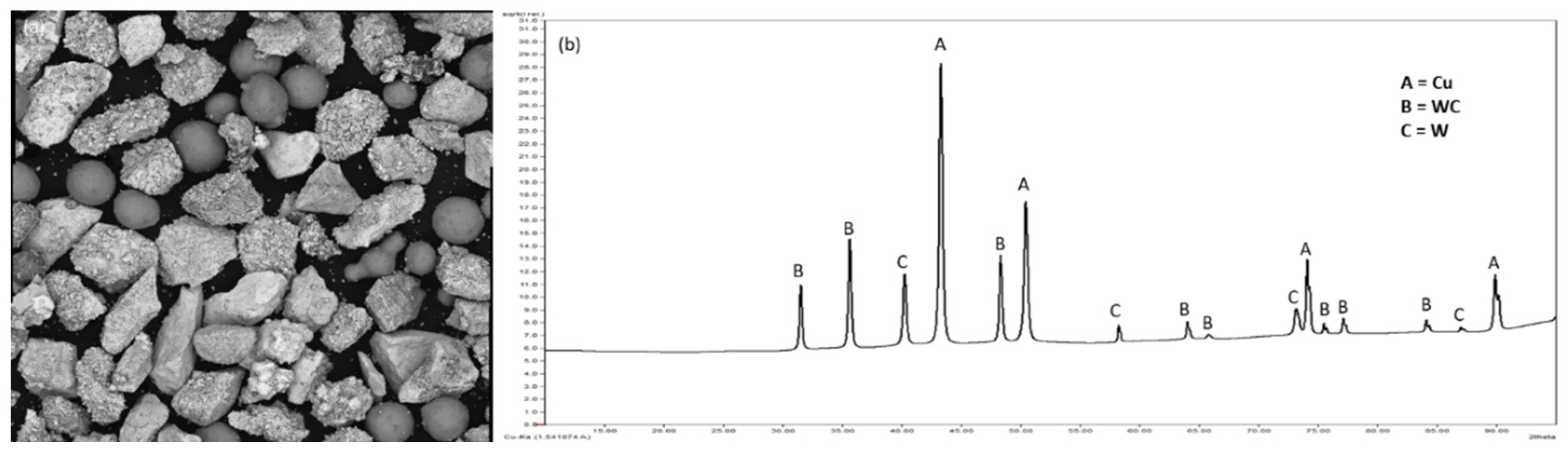
Figure 2.
(a) Single bead, (b) multiple single pass coatings.
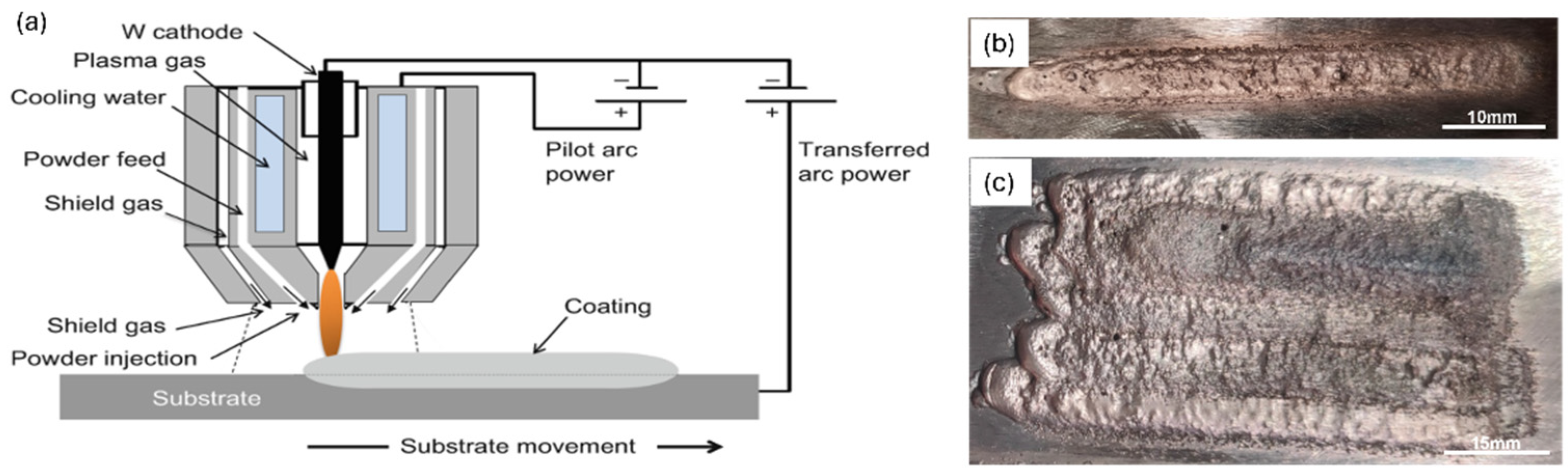
Figure 3.
Microstructure of the composite cladding showing at (a) cross section of cladding; (b) near fusion line; (c) middle; (d) top.
Figure 3.
Microstructure of the composite cladding showing at (a) cross section of cladding; (b) near fusion line; (c) middle; (d) top.
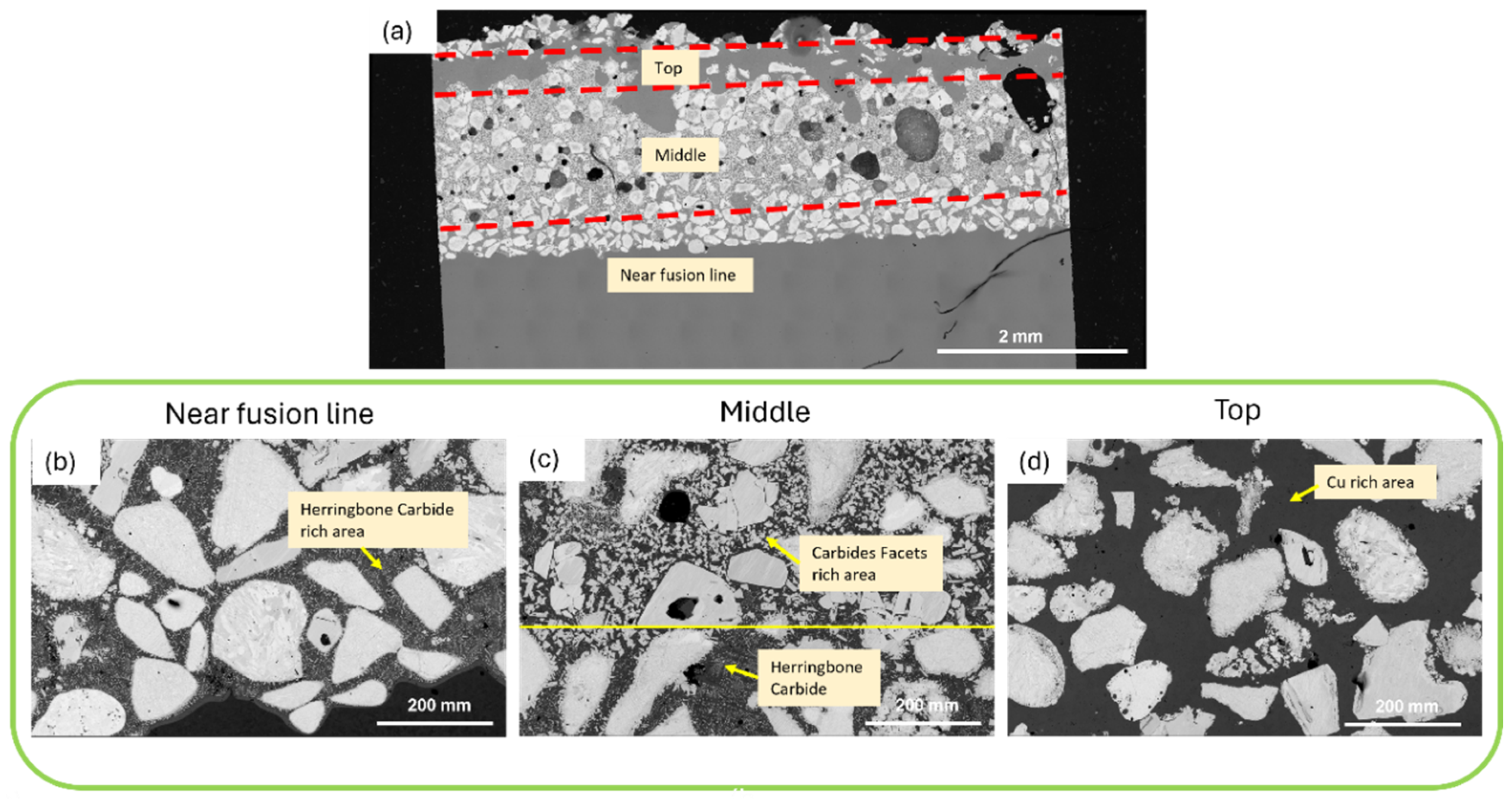
Figure 4.
XRD analysis of the cladding.
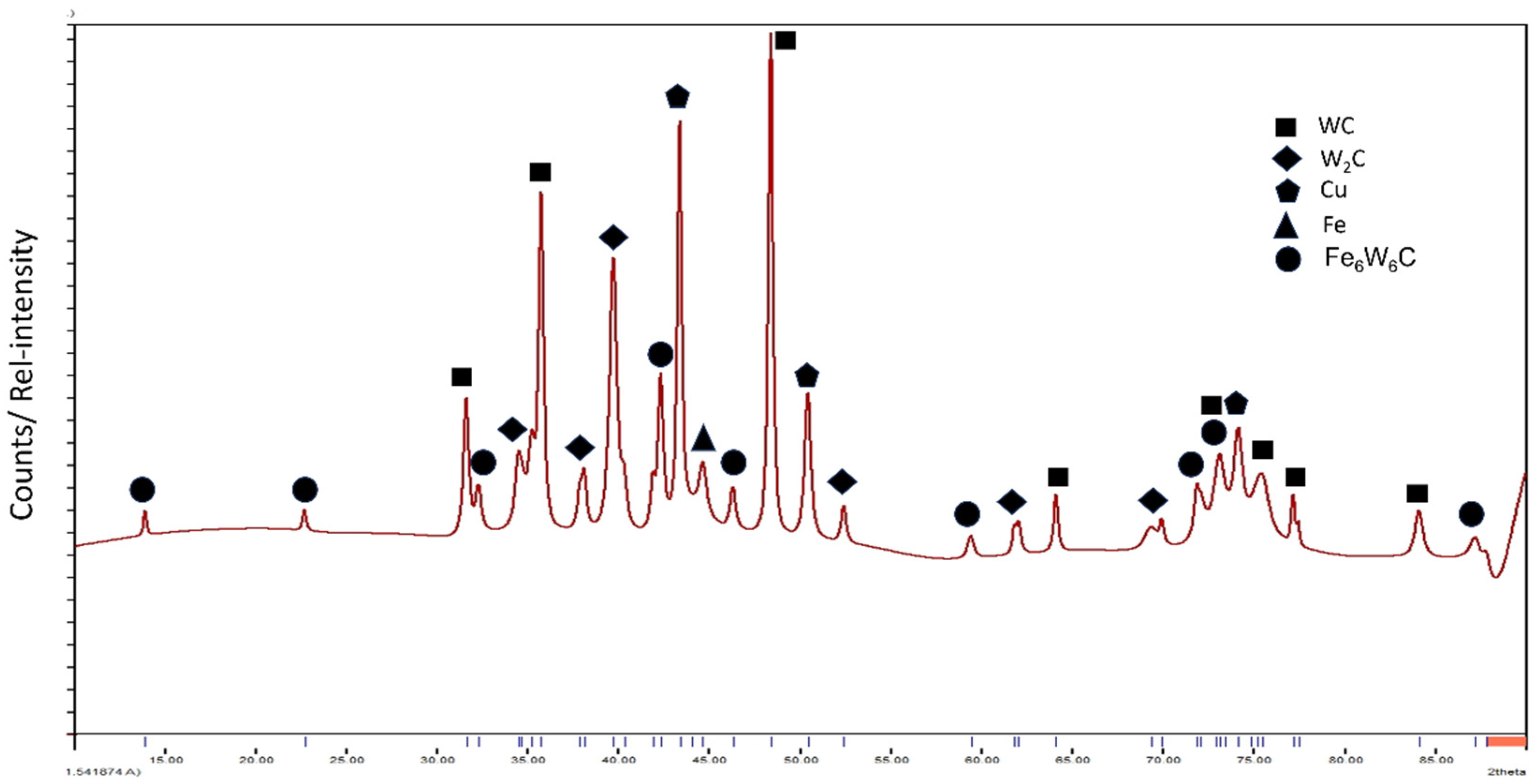
Figure 6.
WC/W2C particles before and after final polishing with OPS + (a) without NH3/H2O2, (b) with NH3/H2O2.
Figure 6.
WC/W2C particles before and after final polishing with OPS + (a) without NH3/H2O2, (b) with NH3/H2O2.
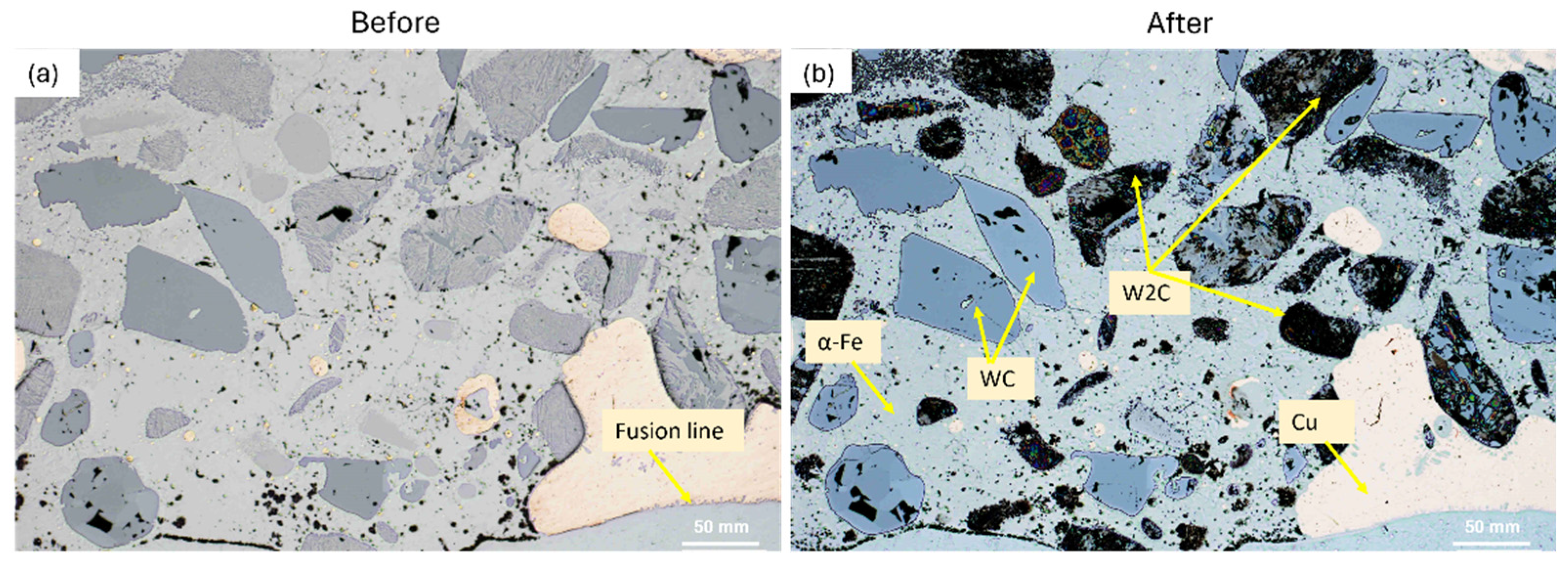
Figure 7.
EDS analysis of the composite at top, middle, and near fusion areas showing the difference of distribution of W, Cu, and Fe content.
Figure 7.
EDS analysis of the composite at top, middle, and near fusion areas showing the difference of distribution of W, Cu, and Fe content.
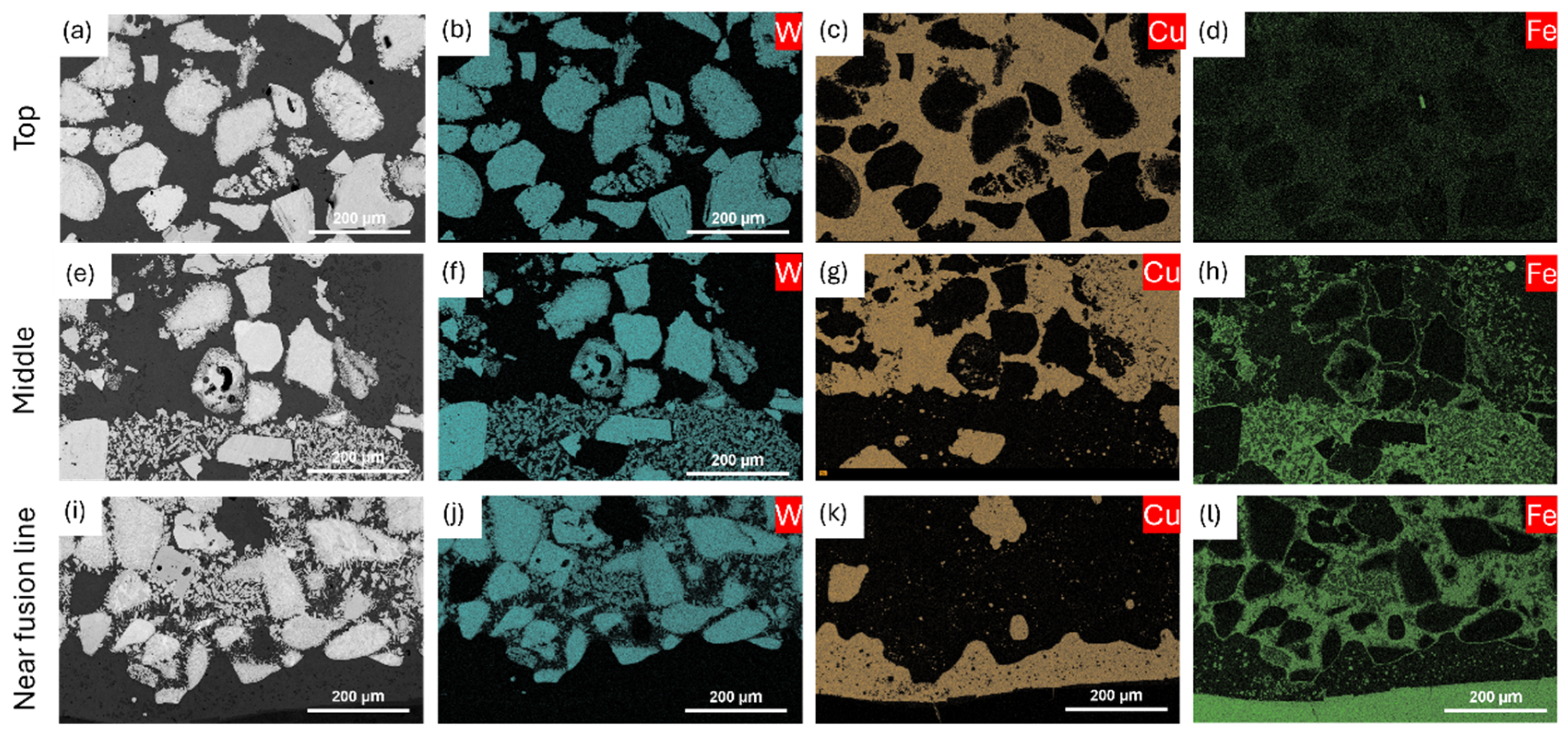
Figure 8.
(a) Spot EDS analysis for ternary carbides and (b), (c), (d), (e) map EDS analysis.
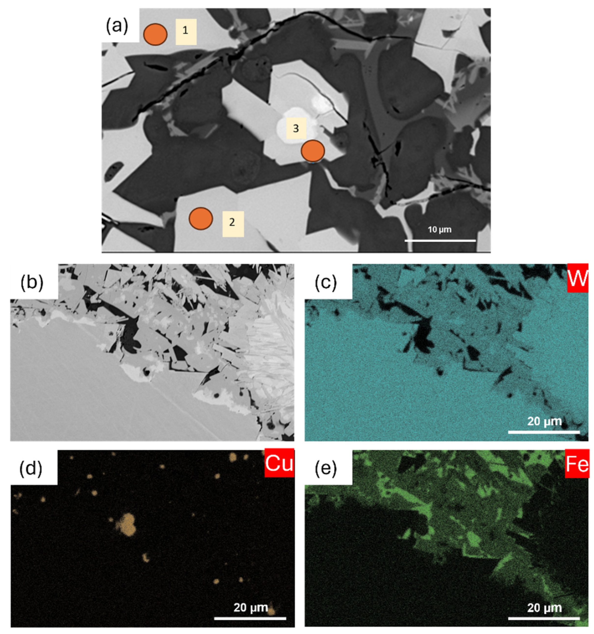
Figure 9.
Microstructure at the (a) Top and (b) near fusion line showing the spheroidal, dendritic growth of Fe with grain boundary diffusion.
Figure 9.
Microstructure at the (a) Top and (b) near fusion line showing the spheroidal, dendritic growth of Fe with grain boundary diffusion.
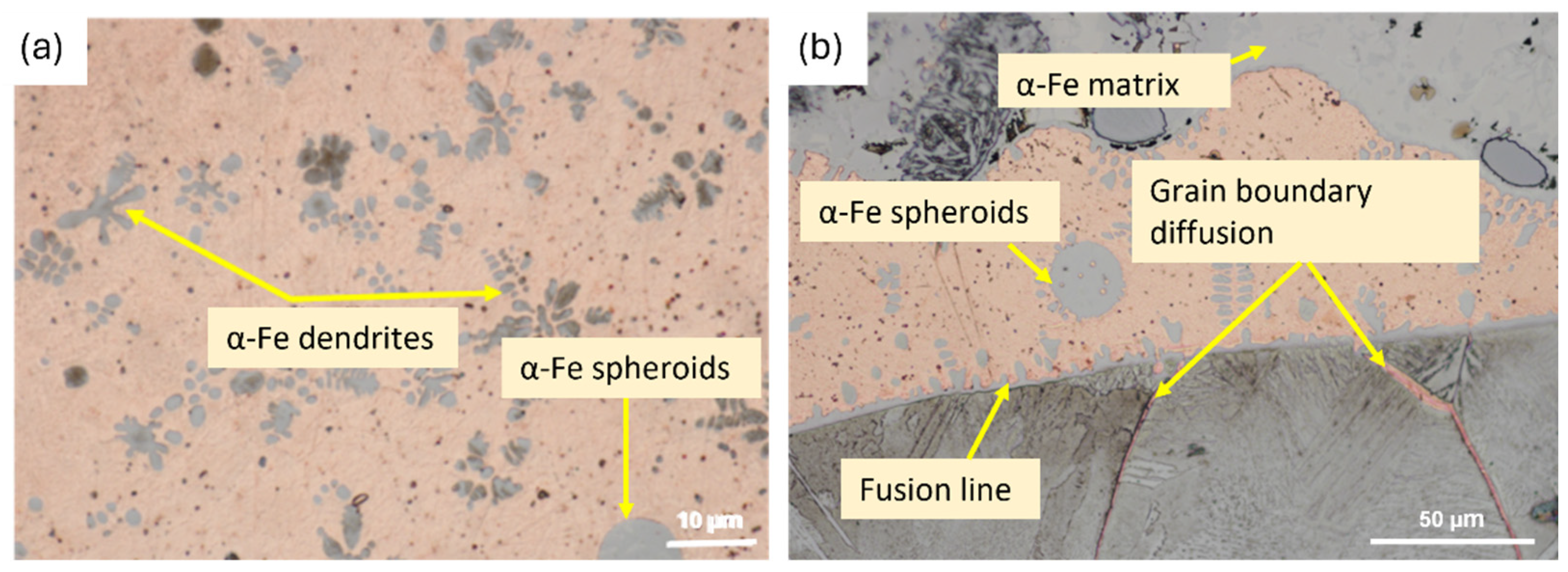
Figure 10.
TEM analysis of the intermetallic; (a) Dendritic and herringbone structure; (b) Conversion of primary M12C dendritic structure into herringbone structure; (c) Selected area HRTEM showing different crystallographic lattice orientations; (d) Lattice spacing calculation using Gatan; (e) selected area crystallographic orientation and its relevant FFT and IFFT images; (f) TEM diffraction indexed pattern.
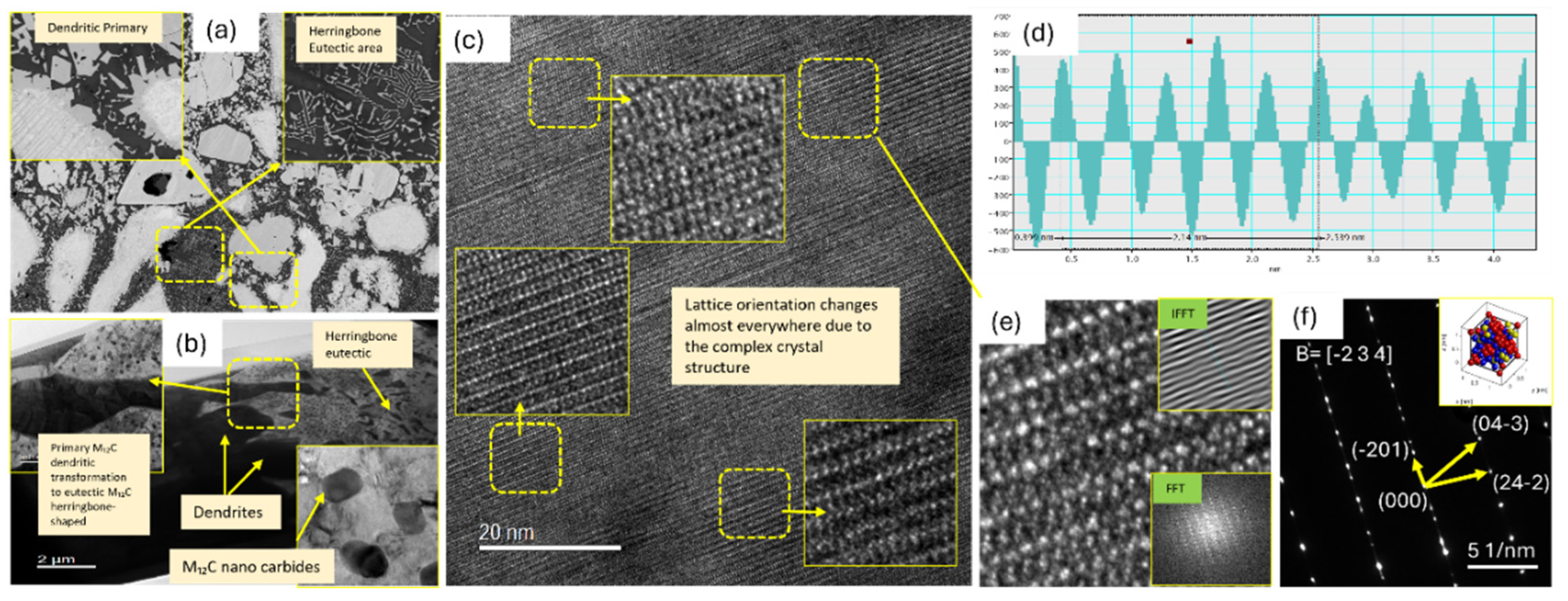

Table 1.
Parameters used for deposition.
| Sr# | Shielding Gas Flow Rate (l/min) | Plasma Gas Flow Rate (l/min) | Shielding Gas Flow for Shielding Hood (l/min) | Powder Feed Rate (g/min) | Current (A) | Travel Speed(mm/sec) | Stand-off Distance (mm) | Powder Flow Gas (l/min) | % Overlapping | Thickness of the Cladding (mm) |
|---|---|---|---|---|---|---|---|---|---|---|
| 1 | 15 | 1.5 | 3.5 | 15.34 | 125 | 2.67 | 12 | 2 | 30 | 1.9 |
Table 2.
Refined structural parameters of the composite using X-ray diffraction.
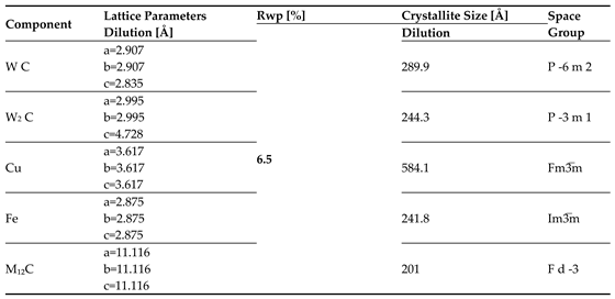 |
Table 3.
Point EDS analysis at three points of the intermetallic phase showing the wt.% of the individual elements.
Table 3.
Point EDS analysis at three points of the intermetallic phase showing the wt.% of the individual elements.
| EDS Point | Fe [wt %] | W [wt %] | C [wt %] |
|---|---|---|---|
| 1 | 24.000 | 70.600 | 5.4 |
| 2 | 23.300 | 71.500 | 5.2 |
| 3 | 23.300 | 71.500 | 5.2 |
Disclaimer/Publisher’s Note: The statements, opinions and data contained in all publications are solely those of the individual author(s) and contributor(s) and not of MDPI and/or the editor(s). MDPI and/or the editor(s) disclaim responsibility for any injury to people or property resulting from any ideas, methods, instructions or products referred to in the content. |
© 2025 by the authors. Licensee MDPI, Basel, Switzerland. This article is an open access article distributed under the terms and conditions of the Creative Commons Attribution (CC BY) license (https://creativecommons.org/licenses/by/4.0/).
Copyright: This open access article is published under a Creative Commons CC BY 4.0 license, which permit the free download, distribution, and reuse, provided that the author and preprint are cited in any reuse.


