
Submitted:
07 August 2025
Posted:
08 August 2025
You are already at the latest version
Abstract
This work reports on systematic investigation of the microstructure and comprehensive performances of Cu–Fe immiscible composite coatings prepared through the combination of mechanical alloying and laser cladding. The samples were characterized by scanning electron microscopy with an energy dispersive analysis, X-ray diffraction, a digital microhardness tester, current tester, electrochemical analyzer and magnetometer. Results show that the immiscible composite coatings are mainly composed of α-Fe particles dispersion in the ε-Cu matrix due to liquid phase separation, and this is exacerbated in addition of more Fe contents. Concentrated distribution of Fe–rich particles at either the top or bottom of the immiscible composite coatings are driven by the dominant mechanism of Marangoni and Stokes motion. With the increased fraction of Fe content, the microhardness and electrical resistivity increased, but a degradation in corrosion resistance. With the increased ball milling time, the electrical resistivity increased and the corrosion resistance is improved. Compared to the medium-carbon steel substrate, the immiscible composite coatings can achieve an improved corrosion resistance, as well as a maximum saturated magnetization of 10.172 emu/g and lowest coercivity of 17.249 Oe.
Keywords:
Laser cladding
; mechanical alloying
; Cu–Fe immiscible composite coatings
; microstructure
; comprehensive performances
1. Introduction
Due to their synergistic multi-phase architecture and exceptional properties, as well as microstructural stability, Cu based immiscible alloys have attracted significant interest in a rich variety of potential applications, such as electronic packaging solders and magnetoresistive materials in the electronic industry, advanced bearings in the automotive industry, and metallic phase change materials (PCM) in latent heat storage systems, etc [1,2,3,4,5,6]. However, the mutual solubility between Cu and Fe in the liquid state is very limited; Cu–Fe melt tends to undergo liquid phase separation during solidification: a Cu–rich melt and a Fe–rich melt. This results in severe macrosegregation, inhomogeneous structures, and reduced properties [7,8,9,10]. Thus, controlling liquid phase separation is essential to achieve uniform structures and enhance the overall performance of Cu–Fe immiscible alloy.
To address the challenge of liquid phase separation between Cu and Fe, extensive work [11,12,13] has been reported on the preparation methods for Cu–Fe immiscible alloy, such as rapid solidification, mechanical alloying, and laser-based methods. Though gravity–driven microstructural segregation can be mitigated by microgravity adjustment, the rapid growth and coalescence of minority phase droplets are still difficult to suppress, due to the persistent influence of Marangoni–driven convection [14,15]. Compared to the above-mentioned methods, Laser cladding can be considered as an innovative and viable technique to produce Cu–Fe immiscible composite coatings, due to many advantages including rapid heating and cooling rates, refined microstructure, low dilution, controllable composition, minimal thermal distortion and high bonding strength [16,17,18,19].
Relevant studies [20,21] showed that the rapid solidification by laser cladding can effectively suppress undesirable liquid phase separation tendencies, enhance the uniformity of phase distribution, and stabilize the resulting microstructure. As a result, controllable composition, enhanced mechanical, thermal, and wear properties can be achieved [22,23,24]. To further optimize the microstructure and interfacial characteristics of precursor powders, mechanical alloying has been introduced as a pre-treatment step before the laser cladding process, which leads to a significant refinement of powders and uniform elemental distribution, facilitating the interfacial bonding and diffusion [25].
In this work, a systematic experimental study was undertaken to examine the effect of elements modification and processing parameters of mechanical alloying and laser cladding on Cu–Fe immiscible composite coatings. Microstructure modification and hardness improvement were studied by scanning electron microscopy and micro-indentation respectively. Electrical resistivity, electrochemical corrosion, and magnetic properties were also examined by current conductivity meter, electrochemical analyzer and magnetometer respectively.
2. Materials and Methods
2.1. Materials
Medium-carbon steel with dimensions of 100 × 50 × 5 mm was used as the substrate for this study. The chemical composition of medium-carbon steel is listed in Table 1. Before laser cladding, the surface of the medium-carbon steel substrate was first polished by a grinder and then cleaned in acetone and alcohol. Pure copper and iron powders with the mean diameters of particle sizes around 45.48 and 126.99 μm were employed in this study. The morphology and distribution of particle size for these two kinds of powders are shown in Figure 1. Cu–based monotectic alloy composite powders containing 5, 8 and 12 wt.% Fe particles respectively were mechanically mixed at a speed of 240 rpm for 8, 12, and 16 h with an interval of 20 mins under Ar atmosphere in a planetary ball mill (TJ-2L, procured from a company in Tianjin, China, TECHIN Ltd.). The selected milling balls consist of 304 stainless steel balls in 8 mm diameter and 3 mm ones with a ratio of 3:2, and the powder-to-ball mass ratio was set as 10:1. The mixed powders were dried at 110 ℃ for 4 h and then used as the laser cladding materials.
2.2. Laser Cladding Process
A multi-mode CO2 laser with a maximum output power of 5 kW was used in the laser cladding experiments, and the medium-carbon steel substrate was mounted on an x-y positioning table. High-purity nitrogen gas was used to protect and deliver the mixed powders into the molten pool. The processing parameters were optimized to obtain the crack-free coatings by Laser cladding: laser power of 2 kW, laser scanning speed of 200 mm/min, powder feeding rate of 0.5 g/min, laser beam spot diameter of 3 mm, and overlapping rate of 50%. The schematic configuration of the laser cladding process is depicted in Figure 2. After laser cladding, all the coatings were cut from the substrate, polished, and then etched by FeCl3 solution (5 g FeCl3, 5 mL HCl, and 95 mL H2O).
2.3. Characterization and Test
Microstructure was examined by scanning electron microscopy (SEM) operating at 20 kV (PHILIP-XL30) equipped with an energy dispersive analysis (EDS), and the grain size was calibrated by image software (DT2000). Phase transitions were identified using a D/MAX-2500 X-ray diffraction (XRD, Cu target, voltage 40 kV, current 40 mA) for scanning angle range of 20° to 100° at 6°/min. A HV-1000 Vickers digital microhardness tester with a load of 1.96 N and a dwelling time of 10 s, along the cross-sectional direction away from the substrate to the top of coatings with an interval setting of 0.1 mm. The resistivity of the Cu–Fe immiscible composite coating was tested using a DC power source and a four-probe instrument with current in the range of 180 to 190 mA, and the average value was obtained by 50 times testing for each sample. The electrochemical corrosion resistance was measured by a CHI604E electrochemical analyzer (Chenhua, Shanghai, China) in a 3.5 wt% NaCl solution. A standard three-electrode cell was composed of a working electrode made from a composite specimen with an exposed area of 1 cm2, a platinum counter electrode, and a saturated calomel reference electrode. All the samples were immersed in the 3.5 wt% NaCl solution at room temperature for 1 h to stabilize the open circuit potential (OCP). Potentiodynamic polarization scanning was varied from −1.4 V to 1.0 V at a sweep rate of 2 mV/s. The magnetic properties were examined repeatedly using an MPMS-XL, vibrating sample magnetometer at room temperature with a maximum applied field of 20000 Oe.
3. Results and Discussion
3.1. Morphologies of Cu–Fe Composite Powders
Figure 3 shows the microstructural features of Cu95Fe5 powder with different ball milling time. The mechanically alloyed Cu95Fe5 powders after ball milling for 8 and 16 h revealed a further refinement and polygonal morphology. The particle size and its distribution of Cu–Fe composite powders vary with different ball milling time are presented in Figure 4. The median diameter sizes for Cu95Fe5, Cu92Fe8, and Cu88Fe12 powders without ball milling are around 50 μm, and decreased significantly to 25~30 μm after ball milling for 8 h. However this trend gradually leveled off, even slightly rebound with continuous ball milling, as shown in Figure 4a. The D3 and D98 values of Cu92Fe8 powder without ball milling are approximately 13.82 and 111.15 μm respectively, and decreased significantly to approximately 5 and 80 μm respectively after ball milling, as shown in Figure 4b. Hence, the concentration distribution of Cu92Fe8 powder with ball milling is much better than that without ball milling. Interestingly, the particle size distribution curve in Figure 4b shows fluctuations at the arrow mark, indicating that ball milling for 8 h or much longer can significantly decrease the particle size, but also result in an uneven distribution of Cu92Fe8 powder.
The evolution of morphologies and resulting microstructures of the Cu–Fe mixed powders after ball milling can be explained by particles flattening, cold welding, and fracture [26,27]. The primary constituents of the mixed powder are Cu content, which possesses low hardness but good plasticity. And the small particles were flattened first and cold welded with each other to form larger particles during the initial stage of ball milling. With continuous ball milling, fracture played a dominant role in the mechanical alloying process, leading to the particle size as well as the shape transformed from flat to near-spherical. In addition, the repeated cold welding and fracture between particles resulted in work hardening, which can facilitate the powders’ refinement until the grain size reaches the sub-micro and nanoscale [28].
3.2. Microstructure of Immiscible Composite Coating
Microstructural features of Cu–Fe immiscible composite coatings by layered laser cladding in cross-section with different Fe contents and ball milling time are shown in the SEM images of Figure 5. The presence of spherical Fe–rich particles dispersion into a Cu–rich matrix can be observed in all coatings. With the increased Fe contents, Fe–rich phases tended to aggregate and result in large-sized segregation through all over the regions, especially severity at the top of coatings, and also the internal pores increased. The formation of pores is attributed to the difference in thermal expansion coefficients between Cu and Fe elements. Due to the contraction of heterogeneous regions in rapid solidification, boundary gaps and trapping air could be introduced, leading to the formation of pores. As shown in Figure 5a3, the presence of partial unmelted powders can be seen in Cu88Fe12 coating with ball milling time for only 8 h, while these phenomenon almost disappeared with much longer ball milling time for 16 h (Figure 5b3).
Figure 6 shows the microstructural features of Cu–Fe immiscible composite coatings by single track laser cladding in cross-section. As shown in Figure 6a1, b1 and c1, the presence of three distinct features can be seen in the bottom of all the Cu–Fe immiscible composite coatings. Equiaxial or columnar dendritic microstructure is formed at the combination region between the Cu–Fe immiscible composite coatings and medium-carbon steel substrate, attributed to the well diffusion of between Cu and Fe. Beyond the combination region and far away from substrate, petal-like dendritic microstructure can be observed, due to comparable a slightly smaller extent of the diffusion. The width of combination region in Cu95Fe5 coating is around 6 μm (Figure 6a2 ), and the weight percentage of Cu element is 15.88 wt.% (EDS analysis results shown in Table 2), indicating a well diffusion between coating and substrate, since the solid solubility of Cu in Fe is very poor (less than 3%). In contrast, the widths of combination region in Cu92Fe8 and Cu88Fe12 increased to 11 and 33 μm respectively (Figure 6b2 and 6c2 ). This can be explained by a higher melting point of Fe than that of copper and a larger temperature gradient between the molten pool and the substrate, which promotes the Fe–rich phase to solidify first in the combination region and formation of Fe–rich region. And hence, the more Fe contents in Cu–Fe immiscible composite coatings, the more formation of Fe–rich region, and the larger the combination region width is. Comparable higher weight percentage of Fe contents presented in B and C infers that a large number of spherical Fe–rich regions were formed over all through the coating (Figure 6a2 ).
Furthermore, large-sized spherical Fe–rich regions present an increasing tendency from the bottom to the top of the Cu–Fe immiscible composite coatings, as shown in Figure 6b2 , 6b3, 6c2 and 6c3. The possible reason can be explained by the effects of Marangoni motion that induced by the temperature gradient and surface tension gradient between spherical liquid droplets and liquid matrix, and Stokes motion that resulted by the gravity field. The liquid droplets can grow up by way of consuming the smaller liquid droplets due to Ostwald ripening and coalescence through the collisions of liquid droplets [29,30,31]. The velocities of Marangoni motion, , can be determined by the following equations, respectively [32]:
where k and k′ are the thermal conductivities of the matrix and droplet, respectively; η and η′ are the viscosities of the matrix and droplet, respectively; d is the droplet diameter; and is the surface tension gradient between the interface of the matrix and the droplet. From Eq. (1), it can be seen that the droplet Marangoni motion is affected by the surface tension gradient and droplet diameter. With the increased droplet diameter, the droplet motion speed can be improved, prompting the precipitation of large-size Fe–rich phase to float to the top of the coating. The Stokes motion velocity, , can be calculated as:
where ρ and ρ′ are the densities of the substrate and droplet, respectively; g is the gravitational acceleration. From Eq. (2), it can be seen that the droplet Stokes motion is related to the density difference and droplet diameter, so the large-sized precipitated phase tends to move towards the bottom of the coating by the effects of Stokes motion. Thus, the movement velocity of precipitated droplets depends on the ratio of to , that is:
From Eq. (3), it can be seen that when the ratio of is greater than 1, the Marangoni motion plays a dominant role in determination of the droplets movement that towards the top of the coating, while when the ratio is less than 1, the Stokes motion plays a dominant role in determination of the droplets movement that towards the bottom of the coating. The was calculated to be 1 at a droplet radius of 38.1 μm based on data from the literature [32]. Consequently, droplets with diameter size less than 38.1 μm in Figure 6 are not sufficiently large to move either toward the top or bottom of the coating that would be retained in the middle of the coating.
Figure 7 shows the XRD patterns of the Cu95Fe5, Cu92Fe8, and Cu88Fe2 immiscible composite coatings with ball milling for 8 and 16 h respectively. It can be seen that the face-centered cubic ε-Cu phase was detected in all coatings, but neither for the body-centered cubic α-Fe phase, this is attributed to the dispersion of Fe element in the matrix and formation of fine particles.
3.3. Hardness
Figure 8 shows the microhardness of the Cu–Fe immiscible composite coatings with varying compositions and ball milling time. Each point is tested three times to obtain an average value. It can be seen that the variation of microhardness across the combination area is less, indicating homogeneous microstructures and elements distribution across the combination region. The microhardness values of Cu95Fe5, Cu92Fe8, and Cu88Fe12 coatings with ball milling 8 h are 143.6, 149.5, and 154.2 HV0.2 respectively, and the microhardness values of Cu95Fe5, Cu92Fe8, and Cu88Fe12 coatings with ball milling 16 h are 149.1, 157.8, and 158.0 HV0.2 respectively, much higher than that of pure copper (106 HV0.2). This is attributed to amounts of spherical Fe-rich particles dispersed within the Cu-rich matrix. The dispersion strengthening follows Orowan’s theory and is governed by the equation as below: :
where is the shear elastic modulus of the matrix phase, is the Berber vector, μ is Poisson’s ratio, is the particle diameter, is the particle spacing, and is the radius of the dislocation line. From Eq. (4), it can be seen that the narrowing of the particle spacing facilitates the enhancement of strengthening effect, and the increased Fe contents promoting the number of Fe phase precipitation that can just right narrow the precipitation phase spacing, which leads to an increase in microhardness. With the increased ball milling time from 8 to 16 h, the extent of dispersion of Fe-rich particles in the Cu-rich matrix becomes larger, resulting in a slight increase in hardness for the coating with ball milling 16 h than that of the coating with ball milling 8 h.
3.4. Electrical Resistivity
Figure 9 shows resistivity change of the Cu–Fe immiscible composite coatings with varying compositions and ball milling time. It can be observed that the resistivity of Cu–Fe immiscible composite coatings increased as more addition of Fe contents. The electrical conductivity of pure copper at room temperature is 1.7×10⁻² mΩ·mm, while decreased dramatically with elemental doping. According to Hong and Heringhaus et al. [33], the overall resistivity of pure copper is related to the individual resistivity, volume fraction, size, and distribution of its constituent phases. The individual resistivity of the constituent phases can be expressed as:
Where , , and represent the resistivity caused by phonon scattering, impurity scattering, dislocation scattering, and interface scattering, respectively. Phonon scattering is an inherent property of the material and is temperature-dependent, while impurity scattering is caused by impurity elements dissolved in the Cu-rich matrix. Thus, the dispersion of Fe-rich particles in the Cu-rich matrix results in an increase of the resistivity. The resistivity of the coating with ball milling 16 h is larger than that of the coating with ball milling 8 h. This is attributed to the increase in the median particle size of the powder shown in Figure 3. Larger particle sizes are detrimental to the dispersion of heterogenous elements after cladding, and the segregation of heterogenous phases disrupts the continuity of the copper matrix, causing an increment for the resistivity of the coatings.
3.5. Electrochemical Corrosion
Figure 10 shows the anodic polarization curves of the Cu–Fe immiscible composite coatings with varying compositions and ball milling time, in 3.5% NaCl solution at room temperature. The corrosion potential (Ecorr) and corrosion current density (Icorr) according to the intersection of cathode and anode polarization curves were calculated by the Tafel extrapolation method from the respective curves summarized in Table 3. Generally, the corrosion thermodynamics and corrosion rate of a material can be reflected by the corrosion potential Ecorr and current density Icorr, respectively. With larger corrosion potential Ecorr, the corrosion trend is lower down, while the corrosion rate is sped up with larger current density Icorr. All the Cu–Fe immiscible coatings with different compositions have a much higher Ecorr (larger than -0.600 V) and smaller Icorr (less than 6.000×10⁻⁶ A/cm2) than the medium-carbon steel substrate (-0.955 V and 1.973×10⁻⁵ A/cm2). It indicates that the Cu–Fe immiscible coatings significantly improved the corrosion resistance of the medium-carbon steel substrate. Moreover, the Ecorr decreased but Icorr increased with the increased fractions of Fe contents in Cu–Fe immiscible coatings, while the trends with the increased ball milling time are the very reverse. It indicates that more Fe content addition in Cu–Fe immiscible coatings results in a gradual weakening of the corrosion resistance, while adequate and proper longer ball milling time is beneficial to improve the corrosion resistance. The corrosion resistance of the Cu–Fe immiscible composite coatings is relatively higher than that of medium-carbon steel substrates, attributed to the formation of microcells by potential differences between spherical Fe–rich particles and the copper substrate due. Specifically, the high-potential Cu–rich regions and low-potential Fe–rich regions act as large cathodes and small anodes, respectively. Thus, the Fe–rich particles are preferentially corroded, thereby protecting the copper matrix from corrosion. Moreover, bubbles appeared during the electrochemical testing process, indicating that hydrogen gas was released on the cathode side during the corrosion process. The relevant reaction equations can be described as follows:
More addition of Fe contents induce more Fe–rich particles distributed at the top of the Cu–Fe immiscible composite coatings (Figure 6) resulting more intense microcell reactions during electrochemical corrosion and thereby degrade the corrosion resistance. Ball milling for longer time can significantly facilitate the refinement of the Fe–rich particles inside the coatings, impeding their Marangoni and Stokes motions, which in turns results in more concentrated distribution of the Fe–rich particles at the middle rather than at the top of the coatings. Therefore, the microcell reactions at the top of the coatings are suppressed during the electrochemical corrosion, and thereby enhance the corrosion resistance. Interestingly, the Cu95Fe5 coating with ball milling 16 h has a lower current density, and its corrosion potential is also much smaller than that of the Cu92Fe8 and Cu88Fe12 coatings with ball milling 16 h. A lower corrosion current density reflects a higher corrosion resistance for the Cu95Fe5 coating, and its lower corrosion potential could be attributed to the segregation and concentrated distribution of Fe–rich particles at the top of the coating.
3.6. Magnetic Hysteresis Loop Analysis
Figure 11 shows the magnetic hysteresis loop of the Cu–Fe immiscible composite coatings with varying compositions and ball milling time, and the fitted values of the magnetic hysteresis loops are given in Table 4. The values of the saturated magnetization and coercitivy the Cu95Fe5 coating with ball milling 16 h are ~10.172 emu/g and ~17.249 Oe, respectively. Wang et al. [34] produced the CoCrCuFeNiTix high-entropy alloys by arc melting and found that their was lower than 2 emu/g. Therefore, the Cu–Fe immiscible composite coating presents soft ferromagnetic characteristics of low coercivity and high permeability, which can be expected to have a good application as the soft magnetic materials by further improving the distribution of Fe-rich particles in the Cu-rich matrix and adjusting the alloying elements, such as Fe, Ni, Si, Cr and B. Moreover, the magnetic belt ring has a very small area, which is beneficial to reduce the magnetic loss of the immiscible composite coating under external magnetic field.
It is interesting to note that though more addition of Fe contents inside the coatings, due to the limited solubility between the Cu and Fe as well as the rapid solidification during laser cladding process, the Cu–Fe immiscible composite coatings tend to form nano-sized Fe–rich particles, possessing very unstable magnetic moments, which in turns results in a decrease of the overall saturation magnetization strength. Moreover, when Fe–rich particles are surrounded by the Cu-rich matrix, magnetic exchange weakens, preventing the formation of long-range ordered magnetic domain structures. During demagnetization, it is difficult to maintain magnetization, and hence a decrease of remanence is presented. The coercive force is related to the size and distribution of Fe–rich particles in the immiscible composite coatings. Refined and uniformly distributed Fe–rich particles may decrease coercive force due to the size effect. Furthermore, the presence of a non-magnetic Cu-rich matrix reduces the magnetic coupling of Fe–rich particles, making magnetization reversal easier and thereby reducing coercivity.
4. Conclusions
Cu–Fe immiscible composite coatings were successfully prepared by mechanical alloying and laser cladding. The microstructure, microhardness, electrical resistivity, electrochemical corrosion performance and magnetic properties of the Cu–Fe immiscible composite coatings with varying compositions and ball milling time were systematically investigated. More addition of Fe contents can facilitate the formation of much larger-sized segregation of spherical Fe–rich particles in the Cu–Fe immiscible composite coatings, and results in an increment in microhardness and electrical resistivity, as well as a degradation in corrosion resistance. Ball milling had significant influence to improve the distribution of Fe-rich particles in the Cu-rich matrix, and so hence significantly affects the comprehensive performances of the Cu–Fe immiscible composite coatings. With increased ball milling time, the electrical resistivity increases while the corrosion resistance is improved. In addition, soft ferromagnetic characteristics of low coercivity and high permeability for the Cu–Fe immiscible composite coatings were achieved. Thus, combined fabrication via mechanical alloying and laser cladding caused the Cu–Fe immiscible composite coatings for higher performance.
Author Contributions
Cheng Deng: Conceptualization, Methodology, Data curation, Formal analysis, Writing—original draft, Funding acquisition. Tao Xie: Methodology, Data curation, Formal analysis. Zihao Wan: Investigation, Data curation, Formal analysis. Guangjian Feng: Methodology, Formal analysis. Yuanlun Yang: Investigation, Formal analysis. Zhaozhi Wu: Methodology, Formal analysis, Funding acquisition. Xinhua Wang: Conceptualization, Investigation, Funding acquisition. Shengfeng Zhou: Conceptualization, Formal analysis. Jie Chen: Conceptualization, Validation, Supervision, Writing—review & editing, Funding acquisition. All authors have read and agreed to the published version of the manuscript.
Funding
This work was financially supported by the National Natural Science Foundation of China (Grant No. 52374368), Guangdong Provincial Distinctive Innovation Project (Grant No. 2024KTSCX197), Guangdong Provincial Key Construction Discipline Research Capacity Enhancement Project (Grant No. 2024ZDJS028), Guangdong Basic and Applied Basic Research Foundation (Grant No. 2024A1515110026, 2024B1515250002, 2023A1515011785), Key-Area Research and Development Program of Guangdong Province (Grant No. 2024B1111080003), State Key Laboratory of Materials Processing and Die & Mould Technology, Huazhong University of Science and Technology (Grant No. P2024-014).
Data Availability Statement
All the data included in this article are available upon request by contact the corresponding author.
Conflicts of Interest
The authors declare that they have no known competing financial interests or personal relationships that could have appeared to influence the work reported in this paper.
References
- Y. Wu, J. Wang, J. Su, L. Zhang, Z. Gao, Z. Gao, Z. Hou, M. Du, J. Duan, Evolution kinetics and morphology selections of familiar and anomalous core-shell macrosegregation in undercooled Cu75Fe25 immiscible, Materials Today Communications 48 (2025) 113352. [CrossRef]
- C. Wen, H. Yang, B. Guo, D. Sun, L.-C. Zhang, Y. Lu, S. Zhou, Enhanced strength-ductility synergy of amorphous oxide dispersion strengthened Cu–316L–Mo immiscible alloys fabricated by laser powder bed fusion, Materials Science and Engineering: A 943 (2025) 148741. [CrossRef]
- Q. Liu, N. Luo, Z. Fu, B. Niu, X. Wu, X. Wang, D. Mei, Q. Li, B. Song, J. He, Additive manufacturing of immiscible alloys: Breaking the preparation bottleneck and unlocking the property potential, Journal of Alloys and Compounds 1027 (2025) 180544. [CrossRef]
- H. Zhang, X. Wang, J. Liu, C. Liang, H. Zhang, Z. Li, Y. Qiu, Synergistically enhancing electrical conductivity, magnetic properties, and mechanical properties for Cu–5wt% Fe alloy by multi-stage thermomechanical processing, Materials Characterization 227 (2025) 115308. [CrossRef]
- H. Li, H. Yang, X. Wang, J. Cheng, G. Fu, L. Xu, Q. Chai, Microstructural evolution and property correlation of Cu–Fe powders prepared by magnetic field fluidized bed electrodes, Powder Technology 465 (2025) 121379. [CrossRef]
- Y. Wang, C. Liang, H. Cui, J. Jiang, Y. Wang, S. Wu, S. Wei, J. Liu, Phase-field study of the evolution of Cu–rich phase precipitation in Fe–Cu–based quinary alloys, Materials Today Communications 47 (2025) 113164. [CrossRef]
- Y. Wu, B. Zhu, H. Du, Z. Xia, J. Su, Z. Gao, Metastable phase separation kinetics controlled by superheating and undercooling of liquid Fe–Cu peritectic alloys, Journal of Alloys and Compounds 913 (2022) 165268. [CrossRef]
- Y. Li, W. Xia, X. Wang, Y. Ju, T. Liu, D. Zhao, M. Zuo, Effects of cooling rate on the microstructure control and liquid–liquid phase separation behavior of Cu–Fe–P immiscible alloys, Materials Today Communications 33 (2022) 104300. [CrossRef]
- S. Liu, J. Jie, B. Dong, Z. Guo, T. Wang, T. Li, Novel insight into evolution mechanism of second liquid-liquid phase separation in metastable immiscible Cu–Fe alloy, Materials & Design 156 (2018) 71–81. [CrossRef]
- N. Liu, F. Liu, Z. Chen, G. Yang, C. Yang, Y. Zhou, Liquid-phase separation in rapid solidification of undercooled Fe–Co–Cu melts, Journal of Materials Science & Technology 28 (2012) 622–625. [CrossRef]
- J.K. Kim, Y. Shadangi, H.G. Min, V. Shivam, E.S. Park, Alloy design strategies for Fe–rich particle manipulation via unveiling the solidification behavior of Cu–Fe–Si alloys, Materials & Design 256 (2025) 114296. [CrossRef]
- D. Mishra, A. Dhal, X. Li, S. Guo, R.L. Narayan, R.S. Mishra, J. Singh, S.S. Nene, Phase separation induced heterostructure promotes strength-ductility synergy in Cu–rich compositionally complex alloy in as-cast state, Materials Today Communications 44 (2025) 112020. [CrossRef]
- J. Wang, Y. Zhang, T. Wu, Y. Wang, F. Fang, G. Wang, Effects of single/double stage cold rolling and aging treatment on the α–Fe phase, microstructure, and properties of Cu–12Fe–0.42Si–0.008B alloy, Journal of Materials Research and Technology 33 (2024) 9552–9565. [CrossRef]
- N. Wang, L. Zhang, Y.L. Peng, W.J. Yao, Composition-dependence of core-shell microstructure formation in monotectic alloys under reduced gravity conditions, Journal of Alloys and Compounds 663 (2016) 379-386. [CrossRef]
- Y. Peng, N. Wang, Effect of phase-separated patterns on the formation of core-shell structure, Journal of Materials Science & Technology 38 (2020) 64–72. [CrossRef]
- M. Liu, Y. Cai, C. Duan, G. Li, Key techniques in parts repair and remanufacturing based on laser cladding: A review, Journal of Manufacturing Processes 132 (2024) 994–1014. [CrossRef]
- S. Zhao, S. Zhou, M. Xie, X. Dai, D. Chen, L.-C. Zhang, Phase separation and enhanced wear resistance of Cu88Fe12 immiscible coating prepared by laser cladding, Journal of Materials Research and Technology 8 (2019) 2001–2010. [CrossRef]
- Y. Gao, Y. Li, J. Liu, C. Wang, W. Liu, C. Zhang, Research on the elements diffusion behavior and properties in Cu/W composite coatings by high-speed laser cladding/laser remelting, Journal of Alloys and Compounds 1036 (2025) 181746. [CrossRef]
- Y. Jiang, L. Xiao, Z. Peng, M. Li, J. Li, X. Wang, G. Deng, J. Fang, Z. Cai, X. Zhao, S. Liu, Laser cladding of heterogeneous structured Cu–Cr–W–SiC coatings with balanced electrical conductivity and wear resistance, Materials & Design 254 (2025) 114009. [CrossRef]
- H. Ning, Z. Liu, Y. Kong, J. Li, Y. Shen, Study on the dealloying of binary Cu–Fe laser cladding layer with Fe content less than 20 at.%, Acta Materialia 297 (2025) 121342. [CrossRef]
- X. Dai, M. Xie, S. Zhou, C. Wang, J. Yang, Z. Li, Formation and properties of a self-assembled Cu–Fe–Ni–Cr–Si immiscible composite by laser induction hybrid cladding, Journal of Alloys and Compounds 742 (2018) 910–917. [CrossRef]
- H. Yu, Z. Luo, Y. Feng, Z. Liu, G. Xie, R.D.K. Misra, Effect of Cu additions on the microstructure, wear resistance and corrosion resistance of Fe–based/B4C composite coating by vacuum cladding, Surface and Coatings Technology 454 (2023) 129191. [CrossRef]
- Y. Liu, Z. Ye, X. Wang, B. Liang, Y. Zhang, Microstructure and mechanical behavior of Cu–9Al–4Ni–3.5Fe–0.5Mn alloy fabricated by laser melting deposition, Materials Science and Engineering: A 826 (2021) 142006. [CrossRef]
- K.I. Makarenko, S.D. Konev, O.N. Dubinin, I.V. Shishkovsky, Mechanical characteristics of laser-deposited sandwich structures and quasi-homogeneous alloys of Fe–Cu system, Materials & Design 224 (2022) 111313. [CrossRef]
- M. Thit, A. Rocissano, A. Hatem, M. Uddin, C. Hall, T. Schlaefer, Surface integrity and high-cycle fatigue life of direct laser metal deposited AISI 431 alloys modified by plasticity ball burnishing, International Journal of Fatigue 190 (2025) 108614. [CrossRef]
- J. Trapp, B. Kieback, Solid-state reactions during high-energy milling of mixed powder, Acta materialia 61 (2013) 310-320. [CrossRef]
- S.P. Dwivedi, A. Saxena, S. Sharma, G. Singh, J. Singh, M. mia, S. Chattopadhyaya, A. Pramanil, Effect of ball-milling process parameters on mechanical properties of Al/Al2O3/collagen powder composite using statistical approach, Journal of Materials Research and Technology 15 (2021) 2918-2932. [CrossRef]
- M. Riabkina-Fishman, E. Rabkin, P. Levin, N. Frage, M.P. Dariel, A. Weisheit, R. Galun, B.L Mordike, Laser produced functionally graded tungsten carbide coatings on M2 high-speed tool steel, Materials Science and Engineering: A 302 (2001) 106-114. [CrossRef]
- J. He, J.Z. Zhao, L. Ratke, Solidification microstructure and dynamics of metastable phase transformation in undercooled liquid Cu–Fe alloys, Acta Materialia 54 (2006) 1749-1757. [CrossRef]
- N. Liu, F.Liu, W. Yang, Z. Chen, G.C. Yang, Movement of minor phase in undercooled immiscible Fe–Co–Cu alloys, Journal of Alloys and Compounds 551(2013)323-326. [CrossRef]
- I. Kaban, M. Köhler, L. Ratke, R. Nowak, N. Sobczak, N. Mattern, Phase separation in monotectic alloys as a route for liquid state fabrication of composite materials, Journal of Materials Science 47 (2012) 8360-8366. [CrossRef]
- C.P. Wang, X.J. Liu, I. Ohnuma, R. Kainuma, K. Ishida, Formation of Immiscible Alloy Powders with Egg-Type Microstructure, Science 297(5583) (2002) 990-993. [CrossRef]
- S.I. Hong, M.A. Hill, Microstructure and conductivity of Cu-Nb microcomposites fabricated by the bundling and drawing process, Scripta Materialia 44 (2001) 2509–2515. [CrossRef]
- X. F. Wang, Y. Zhang, Y. Qiao, G. L. Chen, Novel microstructure and properties of multicomponent CoCrCuFeNiTix alloys, Intermetallics 15 (2007) 357-362. [CrossRef]
Figure 1.
SEM morphologies of (a) pure copper and (b) pure iron powders; (c) particle size distribution of pure copper and iron powders.
Figure 1.
SEM morphologies of (a) pure copper and (b) pure iron powders; (c) particle size distribution of pure copper and iron powders.
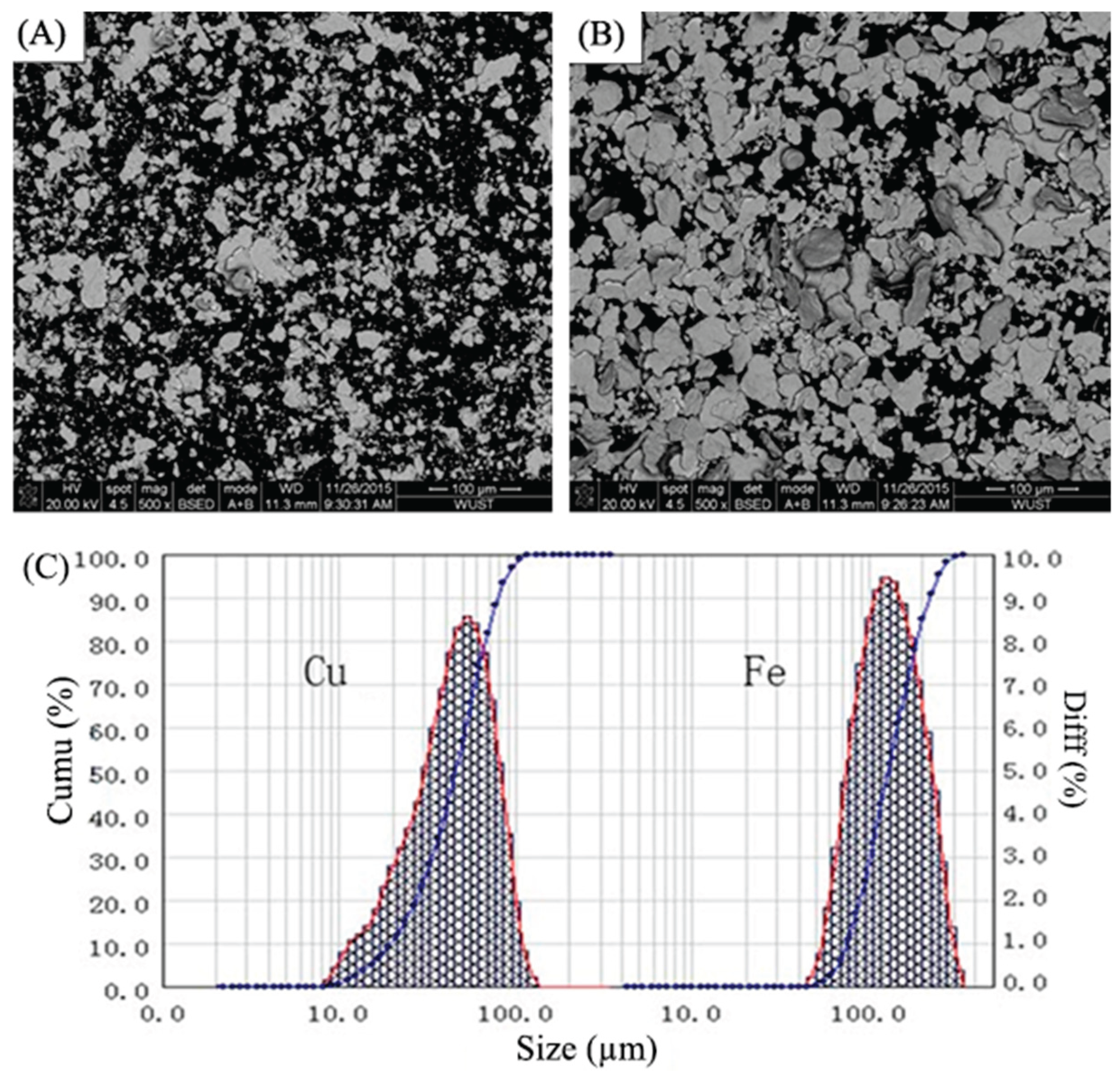
Figure 2.
Schematic of the Laser cladding process.
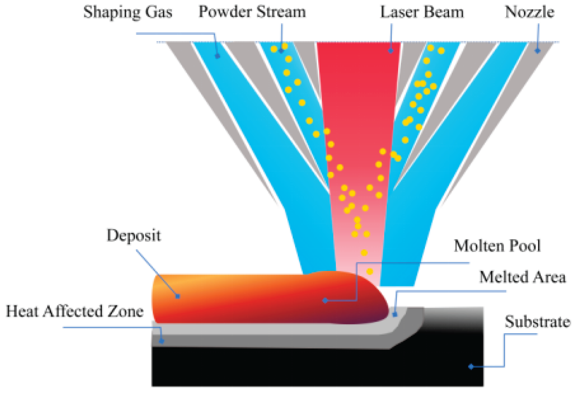
Figure 3.
SEM micrographs of Cu95Fe5 powder: (a) no ball-milling, (b) ball-milling for 8 h, (c) ball-milling for 16 h, (d) ball-milling for 16 h at a higher magnification.
Figure 3.
SEM micrographs of Cu95Fe5 powder: (a) no ball-milling, (b) ball-milling for 8 h, (c) ball-milling for 16 h, (d) ball-milling for 16 h at a higher magnification.
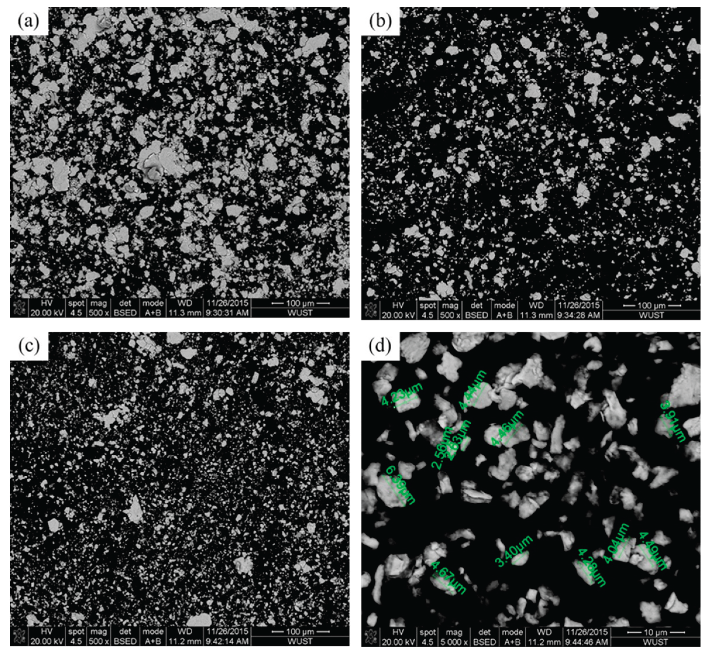
Figure 4.
(a) Median diameter of Cu–Fe composite powders vary with different ball milling time; (b) particle size distribution of Cu92Fe8 powder vary with different ball milling time.
Figure 4.
(a) Median diameter of Cu–Fe composite powders vary with different ball milling time; (b) particle size distribution of Cu92Fe8 powder vary with different ball milling time.

Figure 5.
SEM images of Cu–Fe immiscible composite coatings by layered laser cladding in cross-section. Mechanical alloying conditions are: (a1) Cu95Fe5, (a2) Cu92Fe8, (a3) Cu88Fe12 ball milling for 8 h; (b1) Cu95Fe5, (b2) Cu92Fe8, (b3) Cu88Fe12 ball milling for 16 h.
Figure 5.
SEM images of Cu–Fe immiscible composite coatings by layered laser cladding in cross-section. Mechanical alloying conditions are: (a1) Cu95Fe5, (a2) Cu92Fe8, (a3) Cu88Fe12 ball milling for 8 h; (b1) Cu95Fe5, (b2) Cu92Fe8, (b3) Cu88Fe12 ball milling for 16 h.
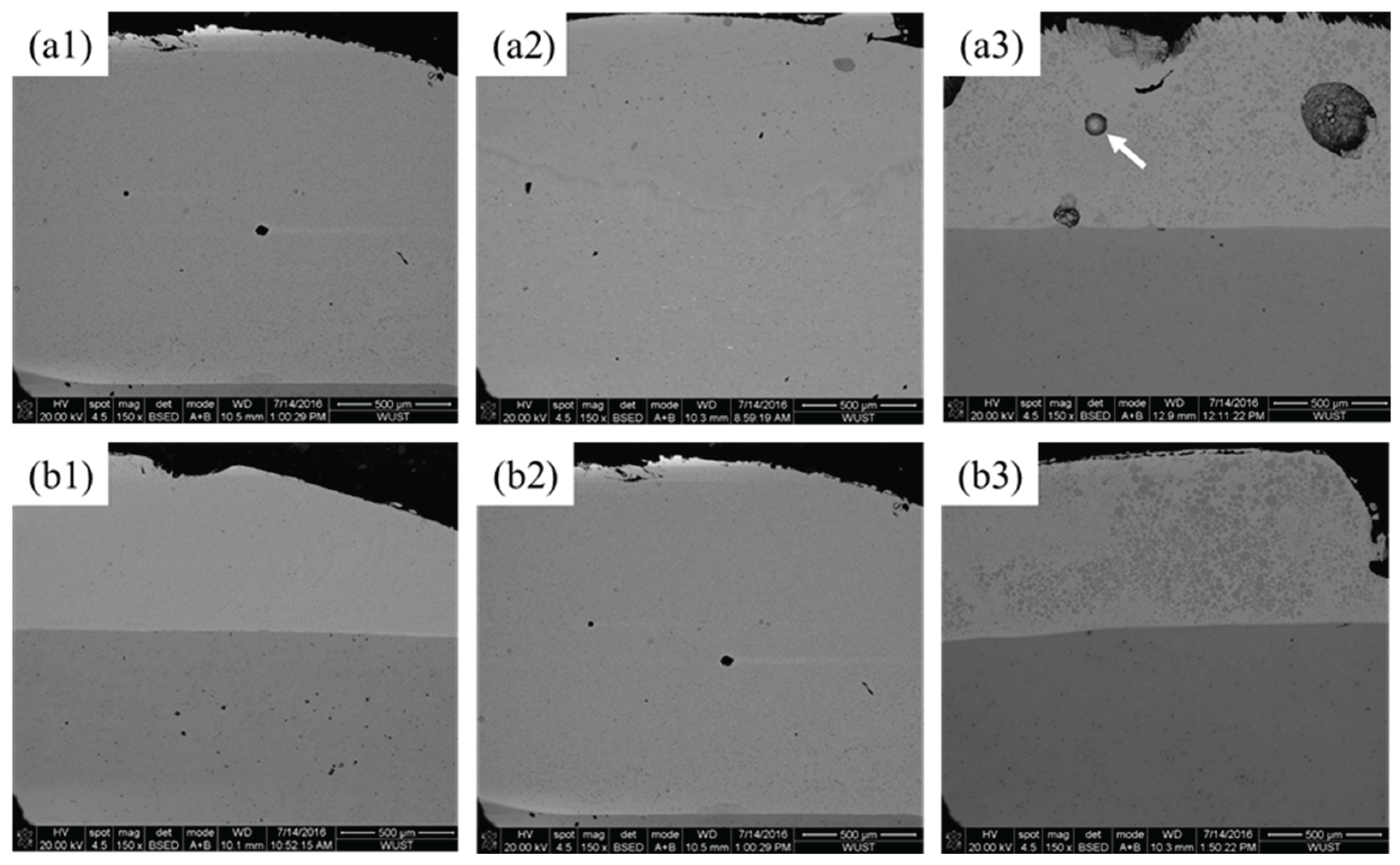
Figure 6.
SEM images of Cu–Fe immiscible composite coatings by single track laser cladding in cross-section: (a1) bottom of Cu95Fe5 coating; (a2) selected regions with distinctive features in (a1); (a3) top of Cu95Fe5 coating; (b1-b3) bottom, middle and top of Cu92Fe8 coating; (c1-c3) bottom, middle and top of Cu88Fe12 coating.
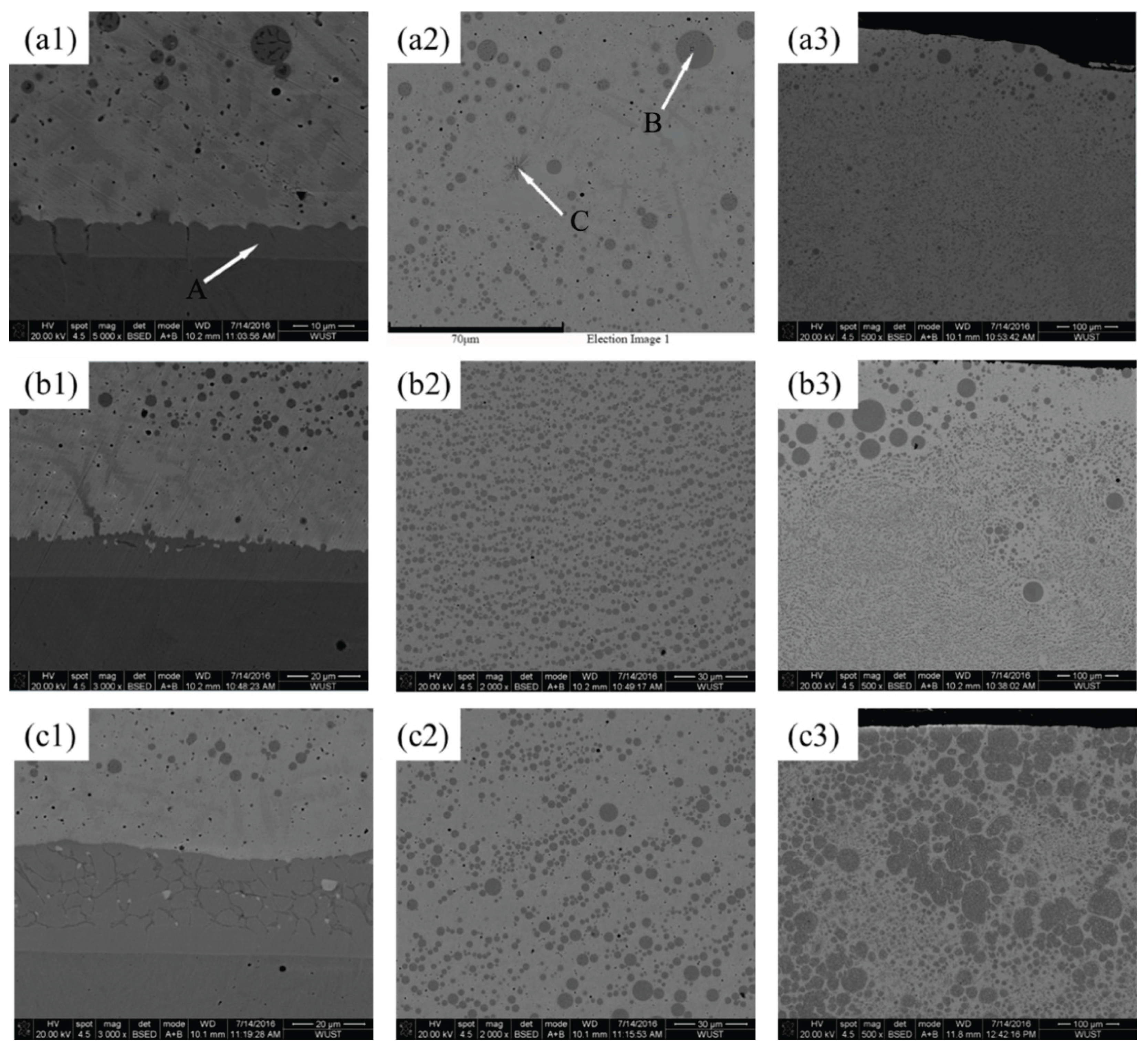
Figure 7.
XRD patterns of Cu95Fe5, Cu92Fe8, and Cu88Fe2 immiscible composite coatings with ball milling for 8 and 16 h.
Figure 7.
XRD patterns of Cu95Fe5, Cu92Fe8, and Cu88Fe2 immiscible composite coatings with ball milling for 8 and 16 h.
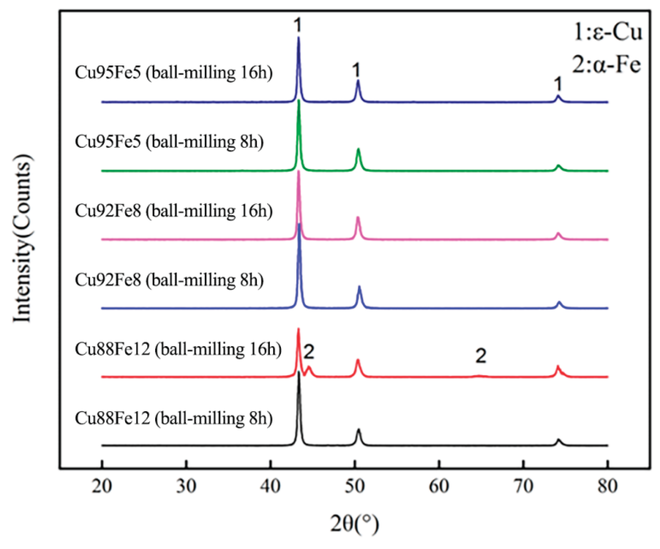
Figure 8.
Hardness results of coatings with varying compositions and ball milling time.
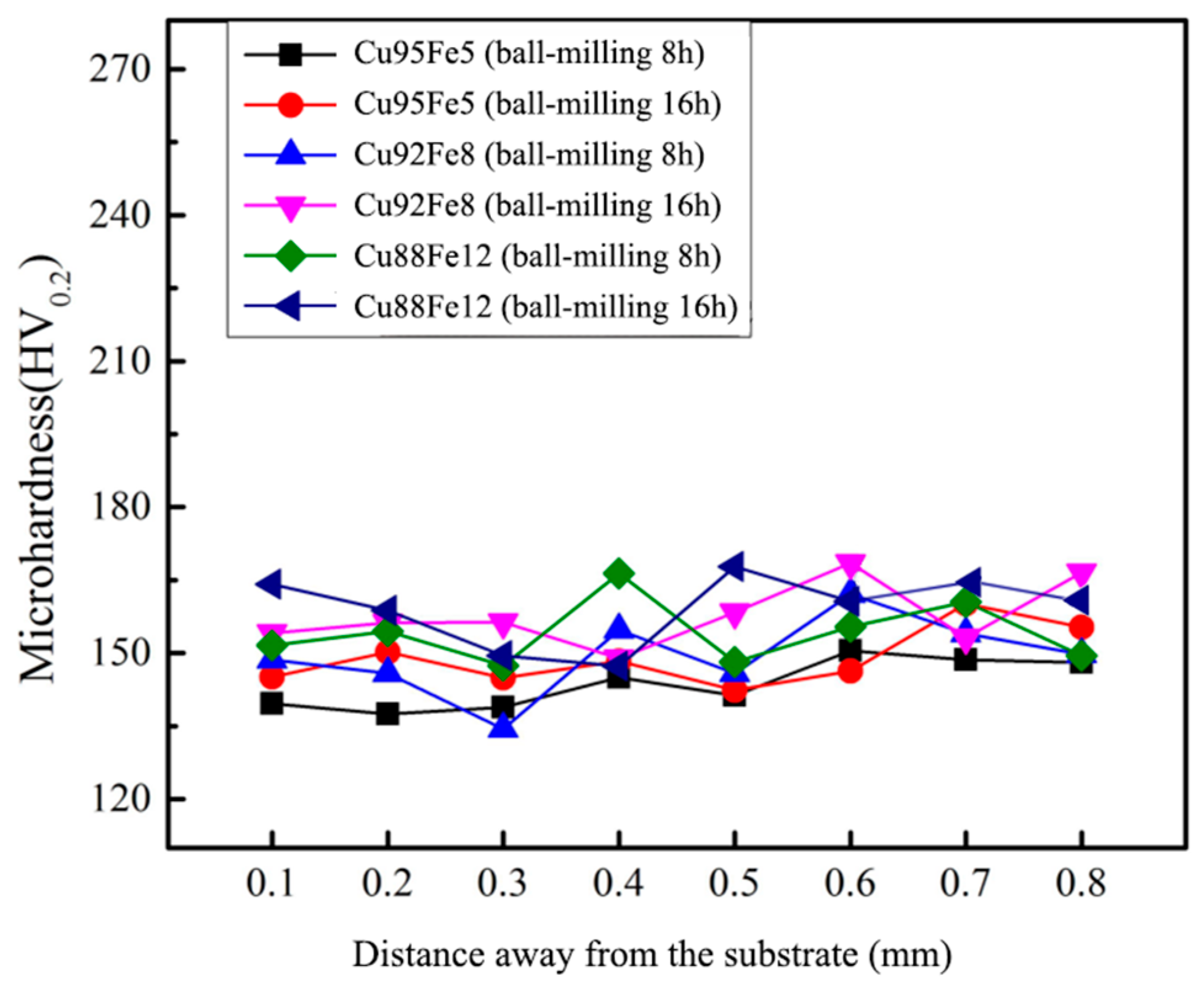
Figure 9.
Resistivity of coatings with varying compositions and ball milling time.
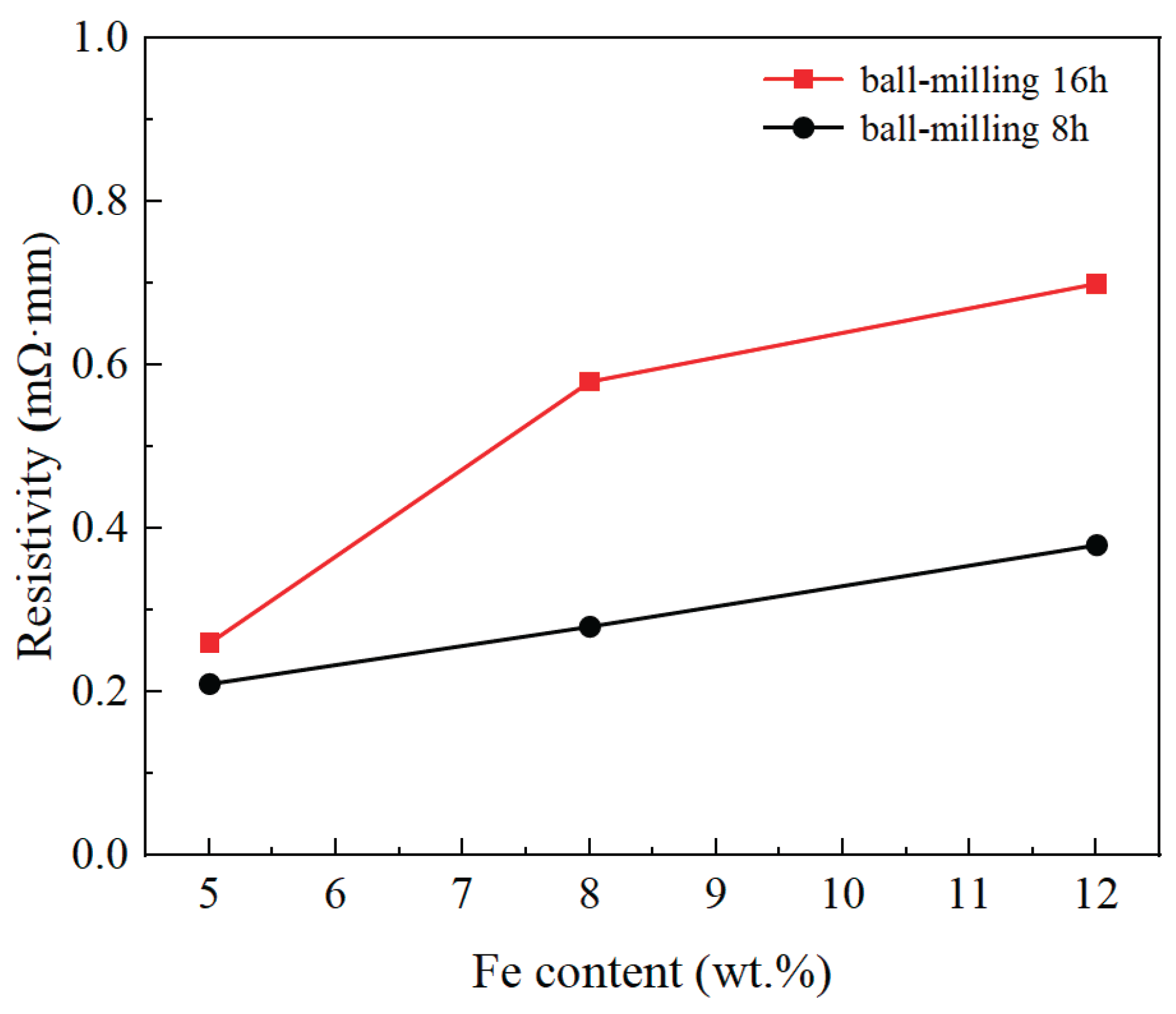
Figure 10.
Potential dynamic curves of the Cu–Fe immiscible coatings in the 3.5 wt% NaCl solution.
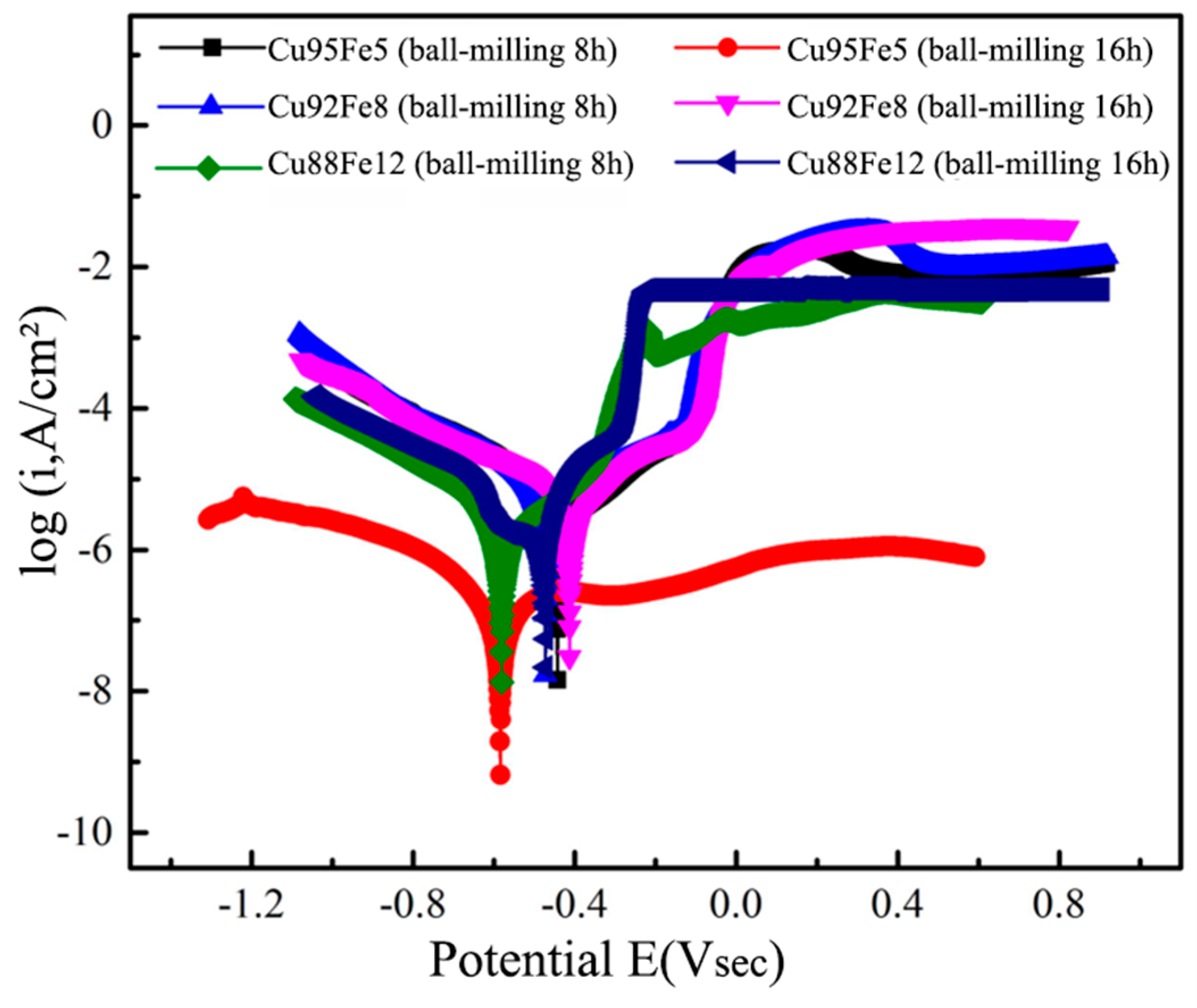
Figure 11.
Magnetic hysteresis loop of the Cu–Fe immiscible coatings.
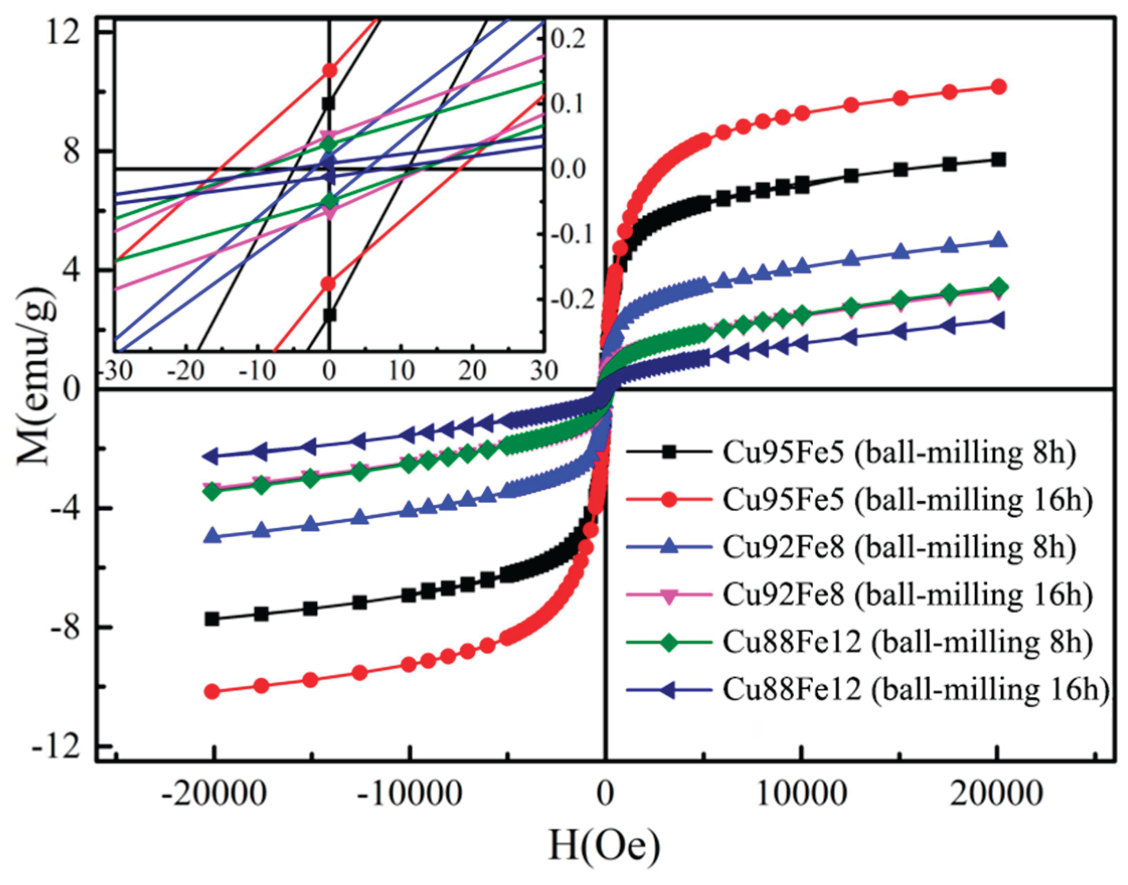

Table 1.
Chemical composition of medium-carbon steel substrate.
| Element | C | Mn | Si | S | P | Fe |
|---|---|---|---|---|---|---|
| Composition (wt.%) | 0.22 | 0.14 | 0.35 | 0.05 | 0.045 | Bal. |
Table 2.
EDS analysis results of coating corresponding to Figure 6a2 and a3.
Table 2.
EDS analysis results of coating corresponding to Figure 6a2 and a3.
| Location | Composition (wt.%) | |||||
| P | Cr | Fe | Ni | Cu | Zn | |
| A | 0 | 6.15 | 60.02 | 17.95 | 15.88 | 0 |
| B | 2.59 | 7.55 | 53.63 | 20.98 | 15.25 | 0 |
| C | 0 | 7.10 | 58.57 | 19.64 | 14.69 | 0 |
Table 3.
Corrosion parameters of the Cu–Fe immiscible coatings in Figure 10.
Table 3.
Corrosion parameters of the Cu–Fe immiscible coatings in Figure 10.
| Sample | Ball-milling time(h) | Ecorr(V) | Icorr(A/cm2) |
|---|---|---|---|
| Cu95Fe5 | 8 | -0.444 | 1.906×10⁻⁶ |
| Cu92Fe8 | 8 | -0.473 | 4.818×10⁻⁶ |
| Cu88Fe12 | 8 | -0.581 | 5.895×10⁻⁶ |
| Cu95Fe5 | 16 | -0.585 | 0.936×10⁻⁶ |
| Cu92Fe8 | 16 | -0.413 | 3.908×10⁻⁶ |
| Cu88Fe12 | 16 | -0.471 | 5.849×10⁻⁶ |
Table 4.
Hysteresis loop fitting values.
| Sample | Ball milling time(h) | Saturated magnetization (emu/g) | Remnant magnetization (emu/g) | Coercive force (Oe) |
|---|---|---|---|---|
| Cu95Fe5 | 8 | 7.723 | 0.175 | 9.858 |
| Cu92Fe8 | 8 | 4.980 | 0.046 | 2.313 |
| Cu88Fe12 | 8 | 3.348 | 0.043 | 1.756 |
| Cu95Fe5 | 16 | 10.172 | 0.163 | 17.249 |
| Cu92Fe8 | 16 | 3.342 | 0.059 | 11.053 |
| Cu88Fe12 | 16 | 2.319 | 0.010 | 4.983 |
Disclaimer/Publisher’s Note: The statements, opinions and data contained in all publications are solely those of the individual author(s) and contributor(s) and not of MDPI and/or the editor(s). MDPI and/or the editor(s) disclaim responsibility for any injury to people or property resulting from any ideas, methods, instructions or products referred to in the content. |
© 2025 by the authors. Licensee MDPI, Basel, Switzerland. This article is an open access article distributed under the terms and conditions of the Creative Commons Attribution (CC BY) license (http://creativecommons.org/licenses/by/4.0/).
Copyright: This open access article is published under a Creative Commons CC BY 4.0 license, which permit the free download, distribution, and reuse, provided that the author and preprint are cited in any reuse.


