Submitted:
24 November 2025
Posted:
25 November 2025
You are already at the latest version
Abstract
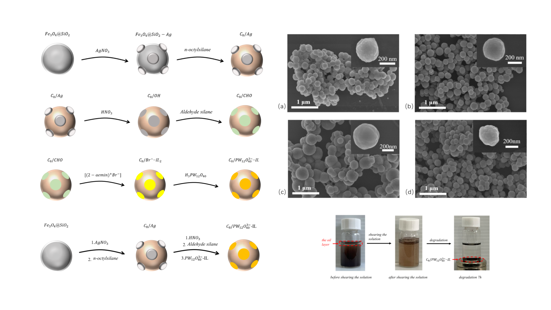
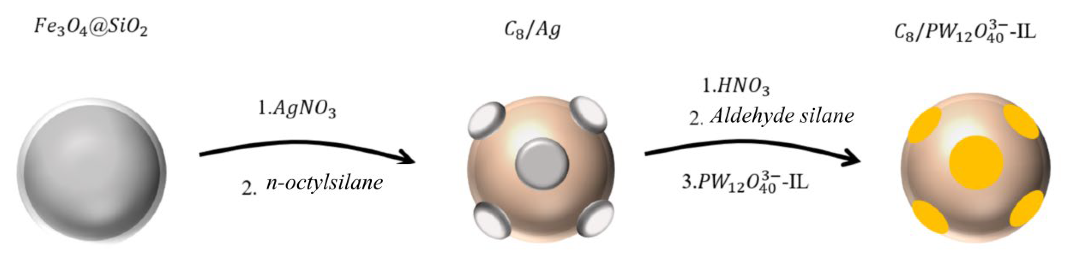
This article presents the design, synthesis and application of novel C8/PW₁₂O₄₀³⁻–IL Janus nanopaticles for highly efficient, recyclable catalytic degradation of methyl orange (MO) in wastewater. The catalyst's innovative asymmetric architecture comprises a hydrophobic C8 hemisphere that selectively adsorbs and pre-concentrates MO molecules, and a catalytic phosphotungstate-ionic liquid hemisphere that activates oxidants to generate hydroxyl radicals for rapid dye degradation. A magnetic Fe₃O₄ core facilitates instantaneous catalyst recovery. This "collect, degrade, and separate" mechanism synergistically results in exceptional performance, surpassing that of many conventional homogeneous and heterogeneous systems, as validated through comparative analysis. This work establishes a strategic paradigm for designing smart, multifunctional materials that combine targeted interfacial engineering with practical recyclability for advanced environmental remediation.
Keywords:
1. Introduction
2. Results and Discussion
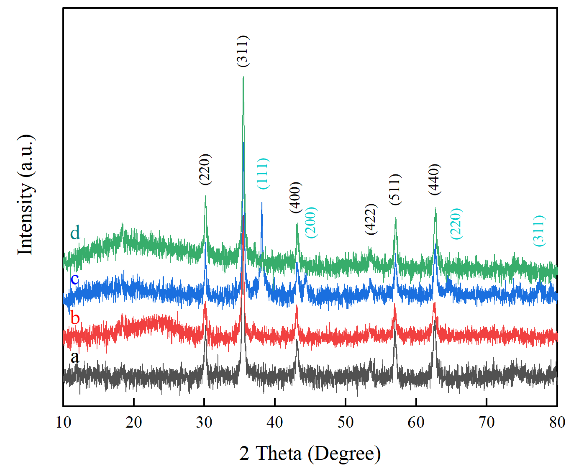
2.1. XRD Analysis
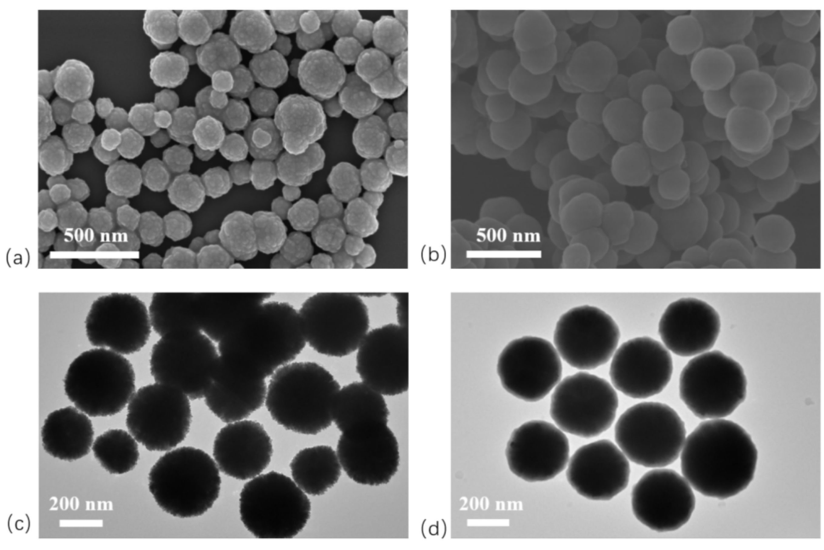
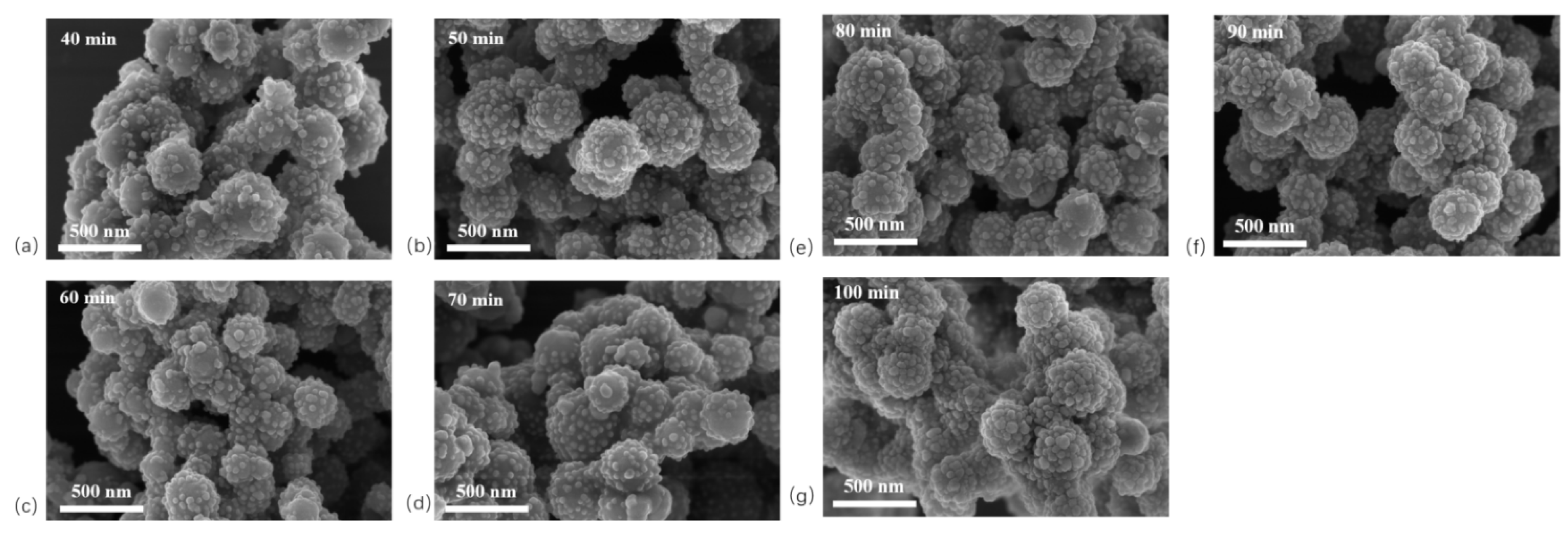
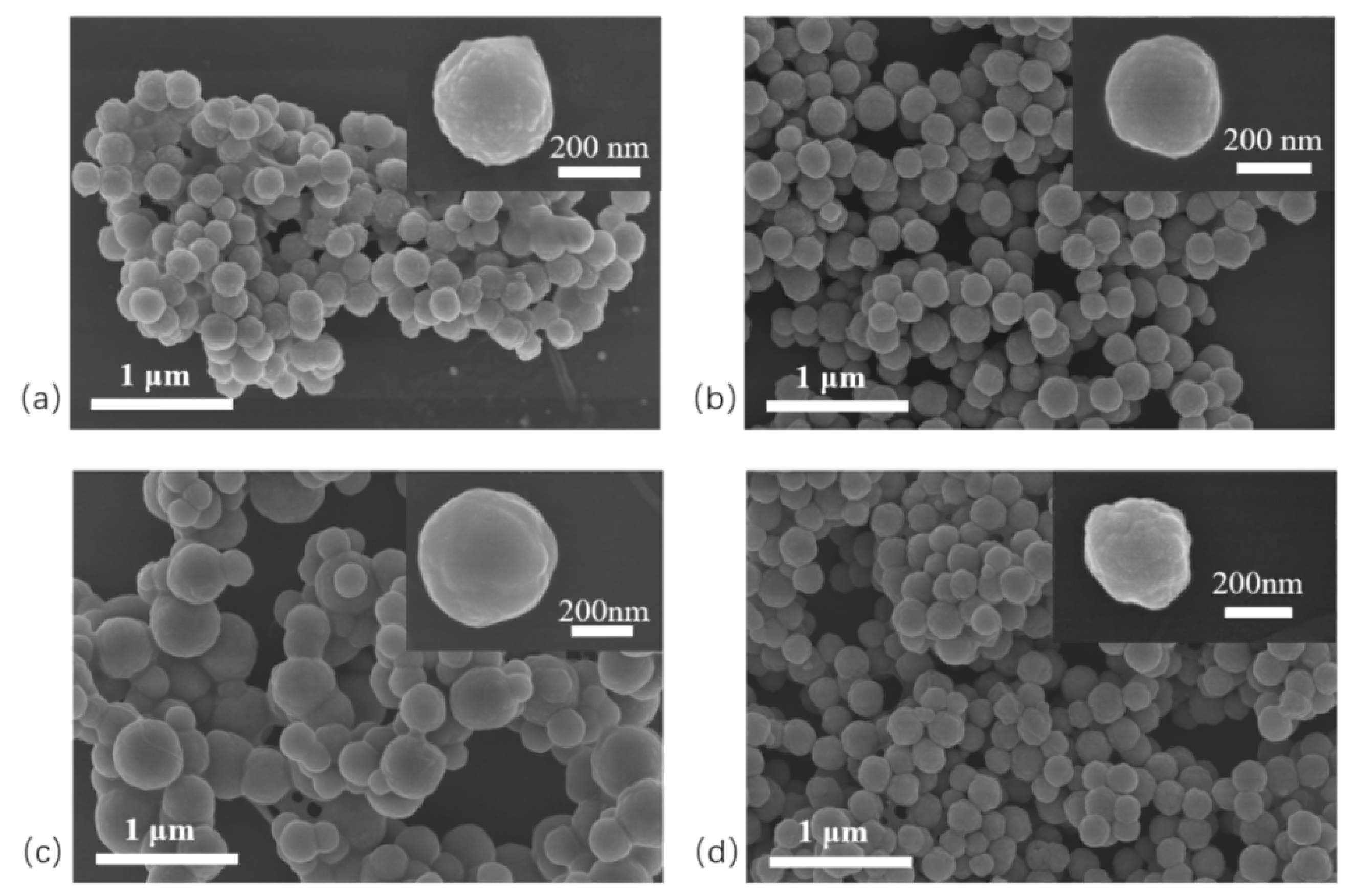
2.2. SEM Analysis
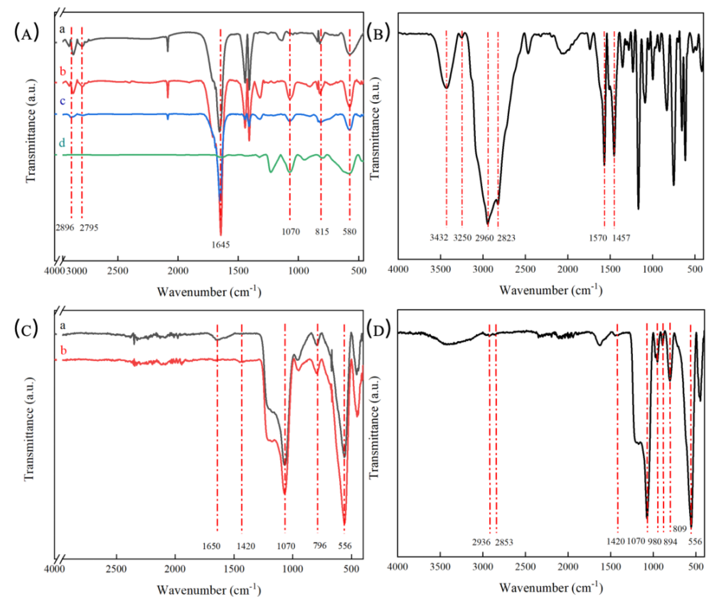
2.3. FTIR Analysis
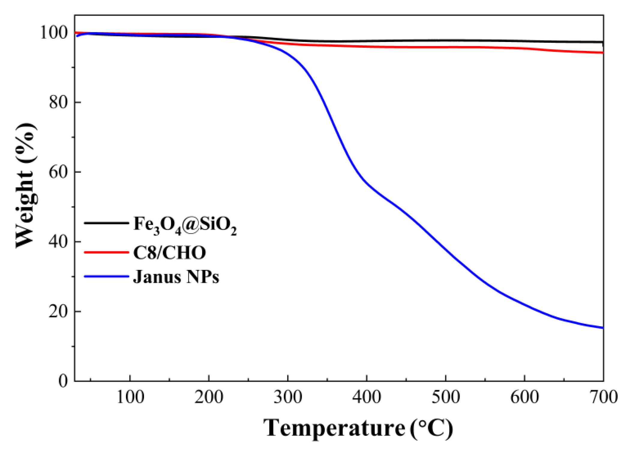
2.4. TGA Analysis
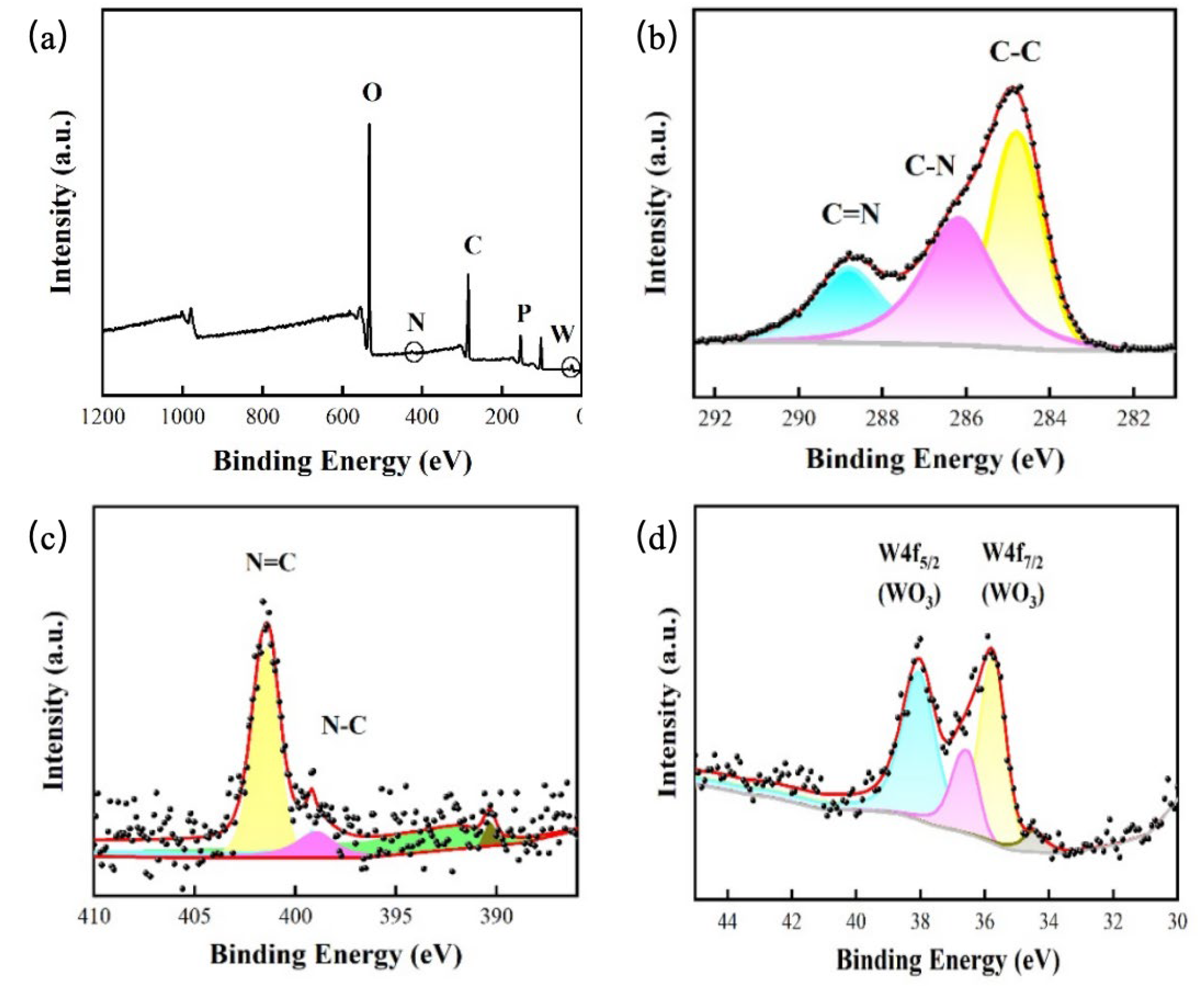
2.5. XPS Analysis
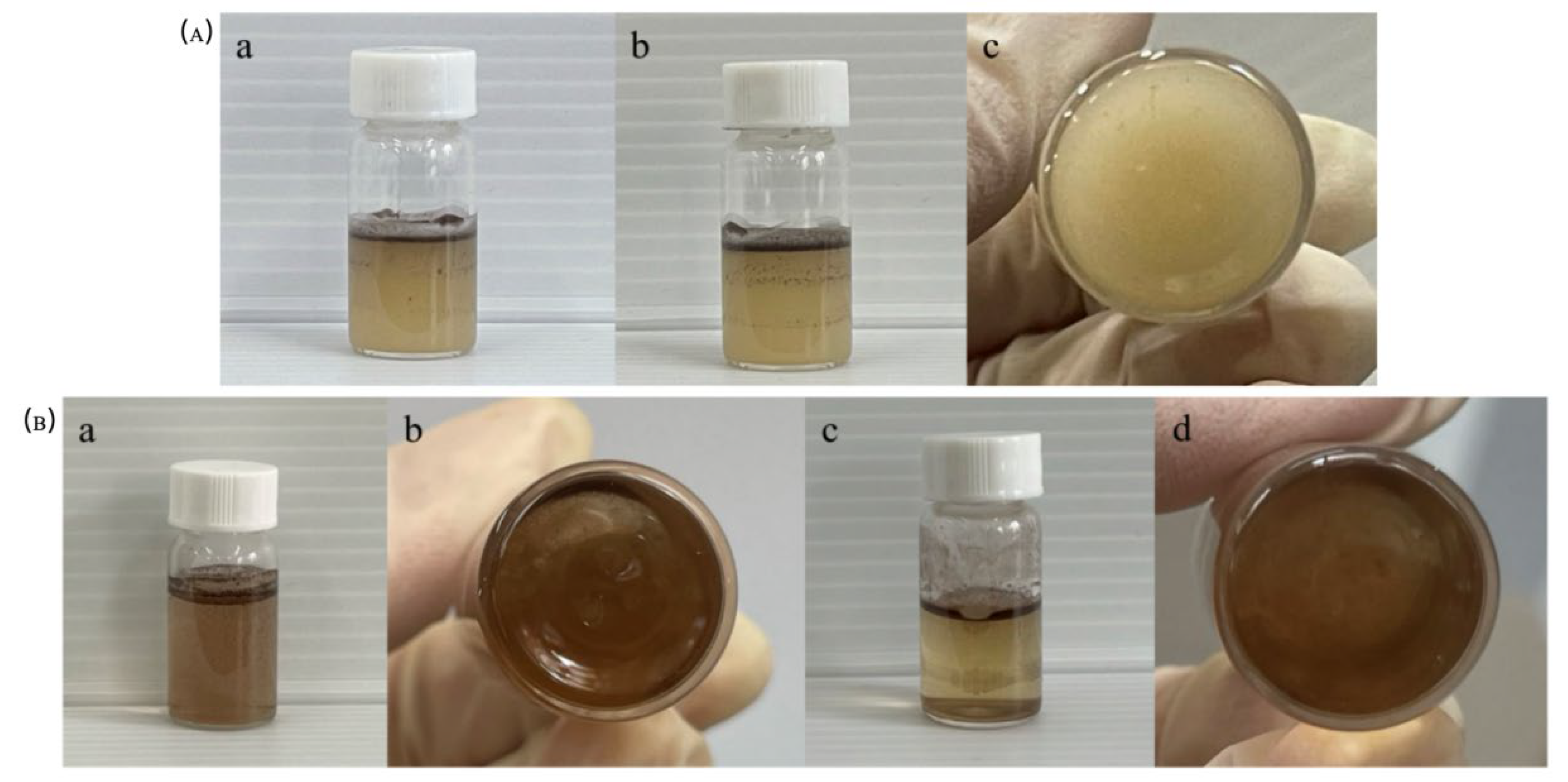
2.4. Emulsification Experiment
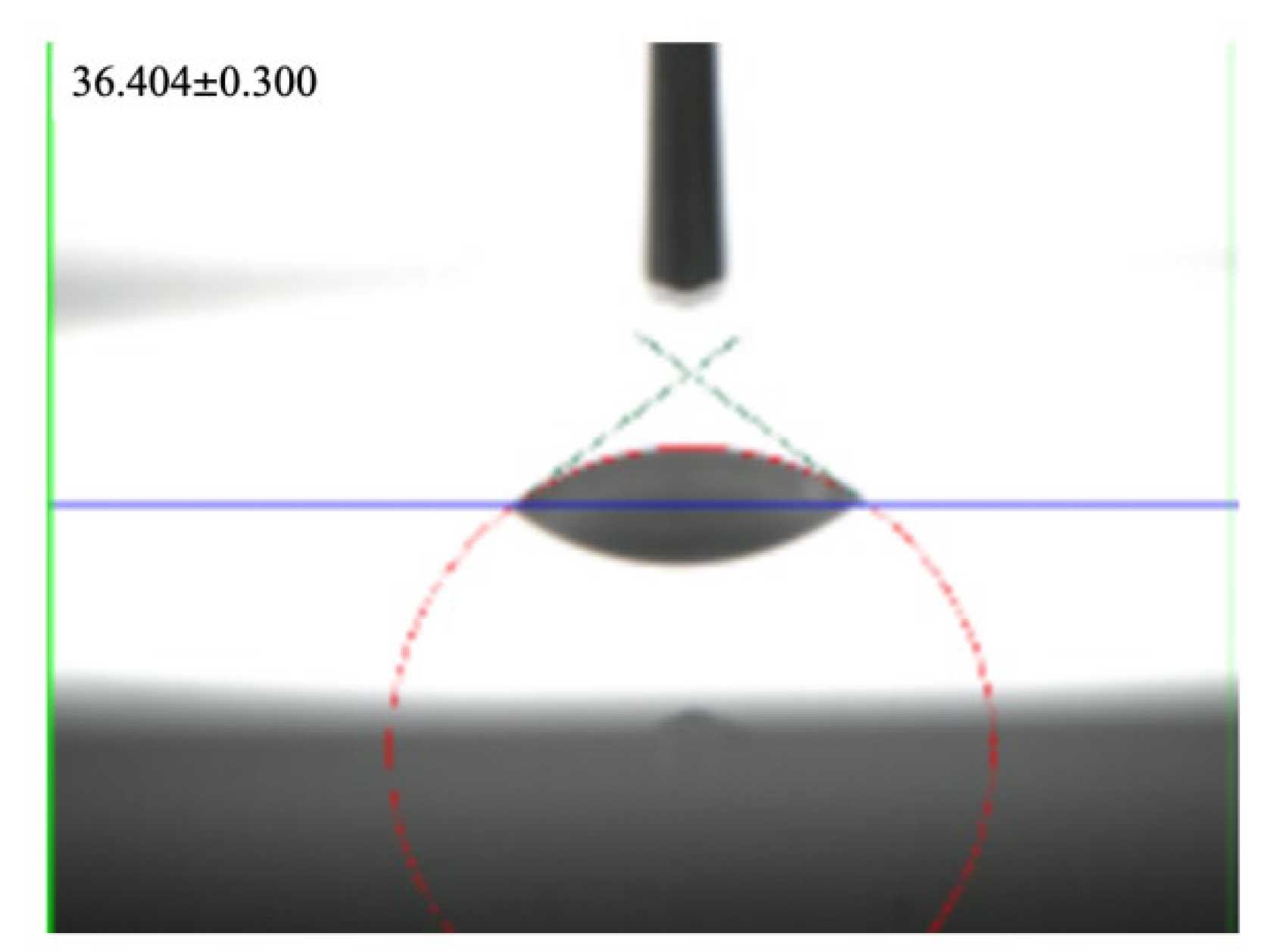
2.5. Contact Angle Test
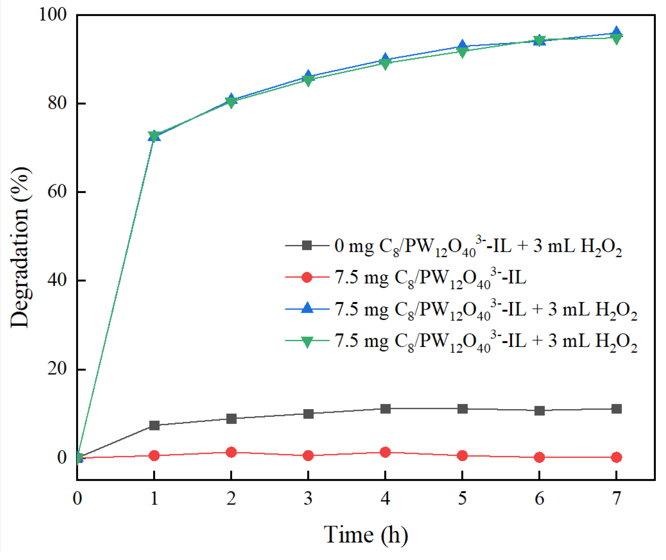
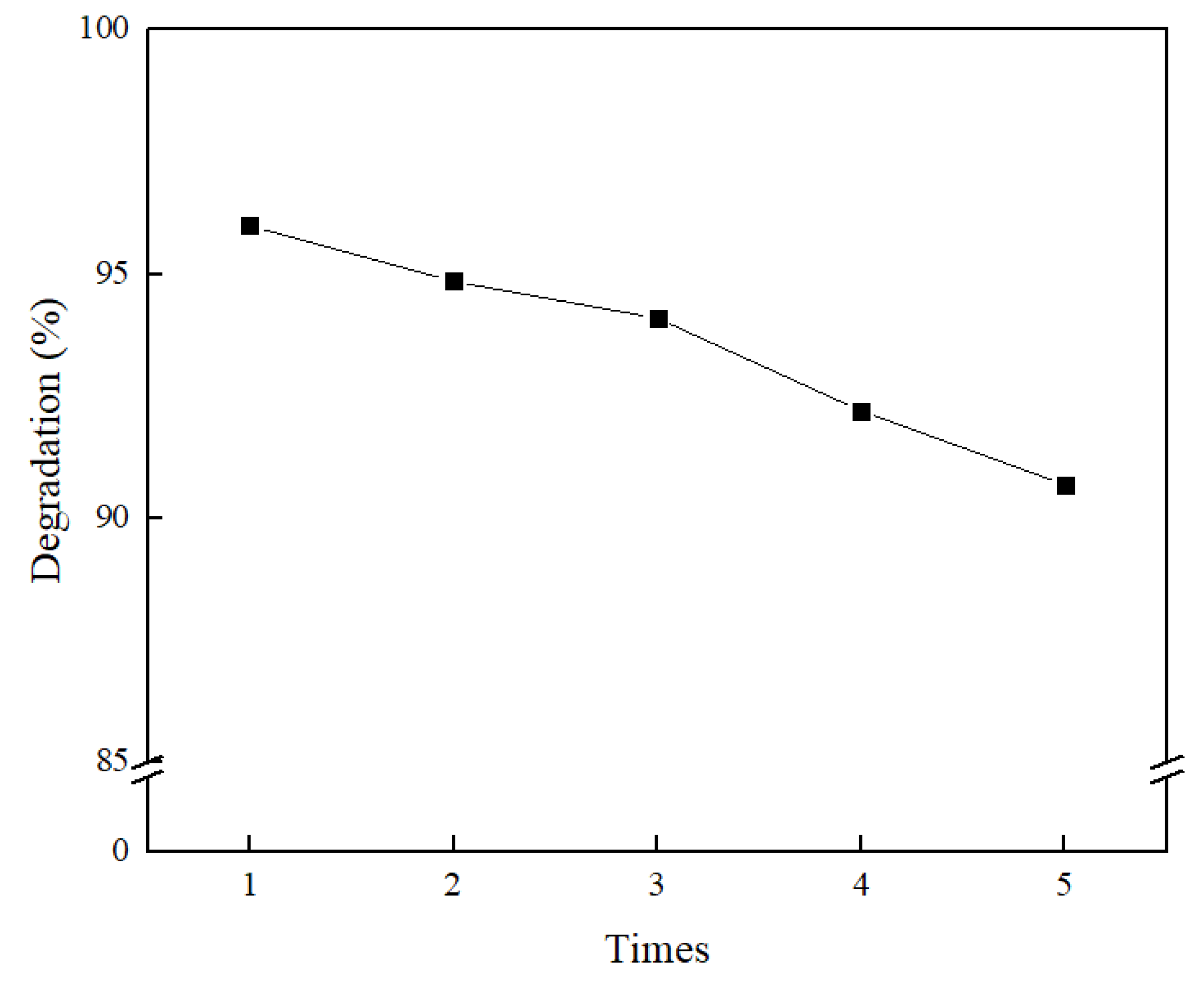
2.6. Methyl Orange Degradation Experiment
3. Experiment
3.1. Materials and Methods
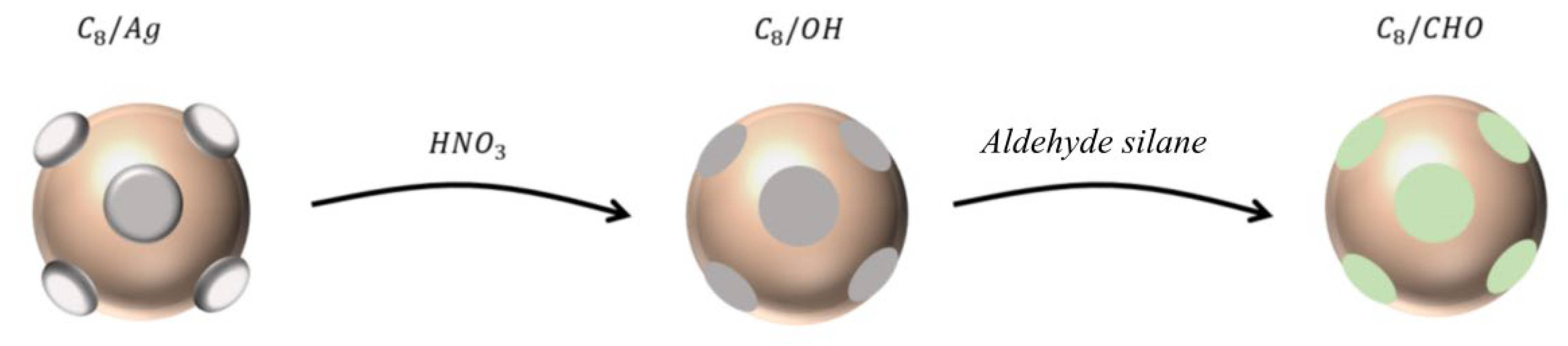
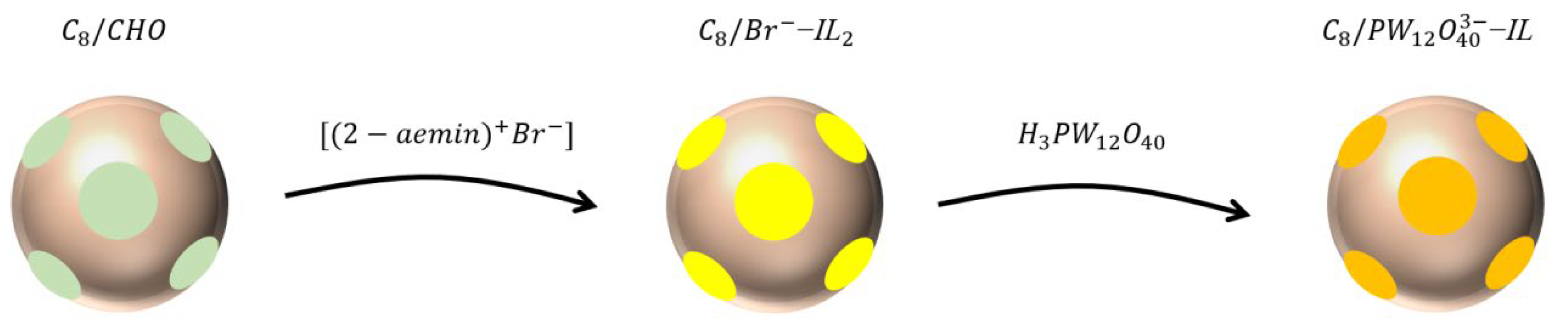
3.2. Sample Preparation
Preparation of C8/Ag NPs
Preparation of 1-(2-aminoethyl)-3-Methylimidazolium Bromide
3.3. Test of Methyl Orange Wastewater
3.4. Material Characterization
4. Conclusions
Author Contributions
Funding
Data Availability Statement
Conflicts of Interest
References
- Gao, Hairong, et al. "Synthesis of Fe 3 O 4/GO magnetic nanomaterials and their adsorption of gentian violet dye." New Chemical Materials 51.11 (2023): 295-300.
- Varjani S, Rakholiya P, Ng H Y, et al. Microbial degradation of dyes: an overview [J]. Bioresource Technology, 2020, 314: 123728.
- Srivastava, Ankita, et al. "Emerging bioremediation technologies for the treatment of textile wastewater containing synthetic dyes: a comprehensive review." Journal of Chemical Technology & Biotechnology 97.1 (2022): 26-41.
- Gao Y, Cao T, Du J, et al. The Bi-Modified (BiO) 2CO3/TiO2 Heterojunction Enhances the Photocatalytic Degradation of Antibiotics[J]. Catalysts, 2025, 15(1): 56.
- Richa, Choudhury A R. Synthesis of a novel gellan-pullulan nanogel and its application in adsorption of cationic dye from aqueous medium [J]. Carbohydrate polymers, 2020, 227: 115291.
- Daniel-González, Guadalupe L., et al. "Characterization of the Enzymatic and Biosorption Processes Involved in the Decolorization of Remazol Brilliant Blue R Dye by Pleurotus ostreatus Pellets." Journal of Fungi 11.8 (2025): 572.
- Cheng Y, Cao T, Xiao Z, et al. Photocatalytic treatment of methyl orange dye wastewater by porous floating ceramsite loaded with cuprous oxide [J]. Coatings, 2022, 12(2): 286.
- Gao Y, Tieping Cao, et al. "Preparation of Bi@ Ho3+: TiO2/Composite Fiber Photocatalytic Materials and Hydrogen Production via Visible Light Decomposition of Water." Catalysts 14.9 (2024): 588.
- Yadav, Sonia, and Nadeem Sharma. "Cerium (III) phosphotungstate: an efficient catalyst in esterification of fatty acids." Zastita Materijala 65.4 (2024): 786-796.
- Sampurnam, S. , et al. "A homogeneous Zr based polyoxometalate coupled with Ppy/PTA for efficient photocatalytic degradation of organic pollutants." Journal of Materials Science: Materials in Electronics 35.2 (2024): 122.
- Maksimchuk, Nataliya V., et al. "Activation of H2O2 over Zr (IV). Insights from model studies on Zr-monosubstituted Lindqvist tungstates." ACS Catalysis 11.16 (2021): 10589-10603.
- Kianfar, Ehsan. "Magnetic nanoparticles in targeted drug delivery: a review." Journal of Superconductivity and Novel Magnetism 34.7 (2021): 1709-1735.
- Kyeong, San, et al. "Magnetic nanoparticles." Nanotechnology for Bioapplications. Singapore: Springer Singapore, 2021. 191-215.
- Gao Y, Meng Q B, Wang B X, et al. Polyacrylonitrile Derived Robust and Flexible Poly (ionic liquid) s Nanofiber Membrane as Catalyst Supporter[J]. Catalysts, 2022, 12(3): 266.
- Liu, Zhe, et al. "Janus particles: A review of their applications in food and medicine." Critical reviews in food science and nutrition 63.29 (2023): 10093-10104.
- Chen, *!!! REPLACE !!!*; et al. "Multi-stimuli-responsive polymer/inorganic janus composite nanoparticles." Langmuir 38.1 (2021): 422-429.
- Galindo C, Jacques P, Kalt A. Photodegradation of the aminoazobenzene acid orange 52 by three advanced oxidation processes UV/H2O2, UV/TiO2 and VIS/TiO2 comparative mechanistic and kinetic investigations [J]. Journal of Photochemistry and Photobiology A: Chemistry, 2000, 130(1): 35-47.
- Xue D, Meng Q B, Song X M. Magnetic-Responsive Janus nanosheets with catalytic properties [J]. ACS applied materials & interfaces, 2019, 11(11): 10967-10974.
- Mahmoud, Maha M., Khaled Chawraba, and Soma A. El Mogy. "Nanocellulose: A comprehensive review of structure, pretreatment, extraction, and chemical modification." Polymer Reviews 64.4 (2024): 1414-1475.
- Geßwein, Holger, et al. "A multipurpose laboratory diffractometer for operando powder X-ray diffraction investigations of energy materials." Applied Crystallography 55.3 (2022): 503-514.
- Al-Harbi, Nuha, and Nabil K. Abd-Elrahman. "Physical methods for preparation of nanomaterials, their characterization and applications: a review." Journal of Umm Al-Qura University for Applied Sciences 11.2 (2025): 356-377.
- Yan, Liu. "Precipitation behaviour of simulated high-level liquid waste during the denitration process based on two-step vitrification." Nuclear Engineering and Design 415 (2023): 112739.
- Datye, Abhaya, and Andrew DeLaRiva. "Scanning electron microscopy (SEM)." Springer Handbook of Advanced Catalyst Characterization. Cham: Springer International Publishing, 2023. 359-380.
- ** Yang, Qingze Chen, Jiaxin ** He, and Jianxi Zhu. "Nanoscale mineralogical characterization of terrestrial and extraterrestrial samples by transmission electron microscopy: A review." ACS Earth and Space Chemistry 7, no. 2 (2023): 289-302.
- Nair, Gopika M., T. Sa**i, and Beena Mathew. "Advanced green approaches for metal and metal oxide nanoparticles synthesis and their environmental applications." Talanta Open 5 (2022): 100080.
- Hao, X. , Allgeyer, E. S., Lee, D. R., Antonello, J., Watters, K., Gerdes, J. A.,... & Bewersdorf, J. (2021). Three-dimensional adaptive optical nanoscopy for thick specimen imaging at sub-50-nm resolution. Nature methods, 18(6), 688-693.
- Del Rosario, Mario, et al. "The field guide to 3D printing in optical microscopy for life sciences." Advanced Biology 6.4 (2022): 2100994.
- Khalid, Khalisanni, Ruzaina Ishak, and Zaira Zaman Chowdhury. "UV–Vis spectroscopy in non-destructive testing." Non-destructive material characterization methods. Elsevier, 2024. 391-416.
- Liu, Yucheng, et al. "Characterization of a novel cellulosic fiber from Broussonetia papyrifera L. bark for green-epoxy composite: Effect of fiber treatment." International Journal of Biological Macromolecules (2025): 144020.
- Moronuki, Nobuyuki, Takeshi Takada, and Alexander Schotten. "Dynamic contact angle measurement on a microscopic area and application to wettability characterization of a single fiber." Langmuir 38.1 (2021): 72-78.


| Catalyst System | Catalytic Type | Optimal Conditions | Performance |
|---|---|---|---|
| This work | Visible Light Photocatalysis | 60 min, 20 mg/L MO, 300 W Xe lamp | 96% Degradation |
| BiOClBrI | Visible Light Photocatalysis | 180 min, 15 mg/L MO, 300 W Xe lamp | 98% Degradation |
| TiO₂ | UV Light Photocatalysis | Not fully specified, partial reflux | 10% Degradation per reaction cycle |
| Porous ZnO Microflowers | Photocatalysis | 300 min, 10 ppm MO, 150 mg catalyst, pH 7 | Highest degradation in 300 min |
| UV/TiO₂ System | UV Light Photocatalysis | 150 min treatment | 74.12% COD Removal, 96.79% Decolorization (120 min) |
Disclaimer/Publisher’s Note: The statements, opinions and data contained in all publications are solely those of the individual author(s) and contributor(s) and not of MDPI and/or the editor(s). MDPI and/or the editor(s) disclaim responsibility for any injury to people or property resulting from any ideas, methods, instructions or products referred to in the content. |
© 2025 by the authors. Licensee MDPI, Basel, Switzerland. This article is an open access article distributed under the terms and conditions of the Creative Commons Attribution (CC BY) license (http://creativecommons.org/licenses/by/4.0/).


