
Submitted:
24 November 2025
Posted:
25 November 2025
You are already at the latest version
Abstract
Conventional structural analysis of hinged precast frame beams (HPFB) often relies on a simplified load distribution method that may not fully account for deformation compatibility, potentially affecting result accuracy. To address this limitation, this paper develops a rigorous analytical framework based on the Winkler foundation model. The framework explicitly incorporates soil-structure interaction (SSI) and enforces static equilibrium and deformation compatibility at all structural nodes and hinges, thereby enabling a mechanically consistent prediction of structural responses. A comprehensive comparative analysis with a traditional frame beam (TFB) reveals the unique mechanical behavior of the HPFB system. Key findings demonstrate the HPFB configuration achieves a drastic reduction in maximum negative bending moment (63.5–83.5%) and shear force (7.8–22.8%), while increasing the maximum positive bending moment by 46–62%. This fundamental shift in internal forces occurs in conjunction with a characteristic segmented deflection profile. Sensitivity analysis further indicates that while the subgrade reaction coefficient significantly influences deflection patterns, its effect on bending moments and shear forces remains marginal. The proposed framework provides designers with a robust and theoretically sound tool for the analysis and design of HPFB structures, ensuring performance reliability while addressing limitations observed in current analytical approaches.
Keywords:
hinged precast frame beam (HPFB)
; traditional frame beam (TFB)
; structural analysis framework
; Winkler foundation model
; soil-structure interaction (SSI)
; subgrade reaction coefficient
; sensitivity analysis
; slope engineering
1. Introduction
The frame beam slope anchoring system, commonly referred to as grid or lattice beam system, has undergone significant development in China over the past four decades [1,2,3,4,5]. This system consists of interconnected reinforced concrete beams constructed on slope surfaces in horizontal and vertical configurations, with typical spacing not exceeding 4.0 m [6]. All beam intersections are anchored using bolts or cables to ensure permanent slope stability(see Figure 1). The construction of these systems follows a sequential procedure involving slope surface trimming, anchor hole drilling and installation, formwork erection and reinforcement cage placement, concrete pouring, and subsequent curing. This extended procedure leaves the slope temporarily unsupported for a long time, raising potential instability risks during construction. Slope instability induced by excavation unloading[7,8,9], rainfall infiltration[10,11,12], mechanical vibrations[13,14], groundwater fluctuations[15,16], or other triggering factors[17,18] poses a widespread challenge in slope engineering worldwide. Such failures, particularly those occurring during construction, can lead to severe consequences, including human casualties, significant economic losses, project delays, and substantial cost overruns. Research on preventive measures to mitigate construction-related slope instability remains a critical and ongoing focus within the field of slope engineering.
For frame beam anchoring systems, replacing traditional cast-in-place frame beams with precast components offers an innovative construction approach. Emerging as early as the 1980s, Japan pioneered the use of prestressed precast reinforced concrete(RC) crossbeam structure for slope stabilization[19,20]. In recent years, China has made significant progress in the development of precast frame beam structures. These systems expand upon the original concept of precast RC crossbeam by incorporating additional straight beams, thereby enhancing both structural integrity and adaptability. Qin et al.[21] investigated the mechanical behavior of precast frame beams, composed of precast crossbeams and straight beams with disconnected ends. In a related study, Dai et al. [22] analyzed the contact pressure and internal forces in frame beams constructed from precast crossbeams and straight beams, considering both unconnected ends and wet rigid connections.
Seeking to optimize the connection methodology for precast elements, Zhang et al.[23] developed an innovative HPFB slope anchoring system(see Figure 2) that effectively balances the limitations of non-connected and rigid wet connections. This system employs hinged joints to interconnect precast components, creating a semi-rigid structural framework and the construction follows a systematic sequence: (1) drilling boreholes from predetermined locations on the prepared slope surface into stable underlying strata and installing anchor cables; (2) positioning precast crossbeams and straight beams on the slope surface and interconnecting them with pin joints; (3) applying prestress to the anchor cables and subsequently locking them at the beam intersections.
Based on research and monitoring data from a slope reinforcement project in Guizhou Province, China, Zhang et al. [23] demonstrated that the HPFB system offers comprehensive advantages over the TFB system in multiple aspects, including construction period, resource allocation, safety management, economic cost, carbon emissions, and supporting effects. Building on this foundation, Zhang’s research team [24,25] conducted systematic investigations into several critical aspects of the HPFB system, covering the manufacturing of precast components, slope anchoring methodologies, structural design principles, and the mechanical performance of hinge connections. Within this multifaceted research framework, structural analysis theory assumes particular importance as it directly governs component design and ensures long-term slope stability. However, despite being an innovative stabilization system, the analytical theory for HPFB structures remains underdeveloped and requires substantial refinement. The current Hunan Provincial Standard [26] recommends applying the inverted beam method for structural analysis, yet this approach fails to adequately account for SSI. To address this limitation, Zhang et al. [27] represented the HPFB as a series of continuous, hinged, multi-segment beams on a Winkler foundation under known loads, whose solution was obtained by applying the boundary and inter-segment continuity conditions.
Current analytical approaches for HPFB structures, including the inverted beam method [26] and the Winkler foundation beam method [27], fundamentally rely on a simplified load distribution technique. This conventional method, originally developed for TFB structures, models the horizontal and longitudinal beams—which lack hinged joints—as semi-infinite or infinite beams resting on a Winkler foundation [28,29]. By applying static equilibrium and deformation compatibility conditions at the anchorage points, the method derives explicit load distribution formulas for various anchorage points within the TFB plane. However, as discussed by Fan et al. [29], this simplified approach does not comprehensively consider the influence of loads acting on other nodes along the beams, considering only the deformation effect induced by the load on the node under analysis. Consequently, even for TFB structures, the method fails to fully satisfy deformation compatibility at the anchorage nodes, thus leading to a suboptimal load distribution. The introduction of hinged joints in HPFB structures fundamentally alters the load transfer mechanisms in both horizontal and longitudinal beams. Applying the TFB-derived simplified load distribution method to such systems may result in less accurate load assignments at anchorage points. As a result, any subsequent structural analysis of individual beams under these incorrect loads yields significantly inaccurate outcomes, since the fundamental deformation compatibility conditions are inherently violated.
The current structural analysis of HPFB structures is constrained by the direct application of the simplified load distribution method originally developed for TFB structures. To advance the analytical capabilities while properly accounting for SSI mechanisms, this paper introduces a novel analytical framework based on the Winkler foundation model that not only accurately characterizes the load transfer mechanism at hinged joints within HPFB systems, but also rigorously satisfies both static equilibrium and deformation compatibility conditions at critical structural nodes. The proposed methodology follows a systematic three-phase procedure. First, the HPFB structure is discretized at anchorage points and hinged joints into individual beam segments resting on a Winkler foundation. Next, the applied loads and beam-end forces are determined by enforcing static equilibrium and deformation compatibility at these critical points. Finally, a mechanical analysis is conducted for each segment under the computed loads and boundary conditions. The proposed analytical framework was validated through a representative HPFB case study, with the investigation systematically evaluating four key mechanical responses: load distribution, beam-end shear forces, deformation patterns, and internal force distributions. Comparative analysis with a TFB structure under identical conditions revealed fundamental behavioral differences, while a parametric study further quantified the influence of the subgrade reaction coefficient on the HPFB’s structural behavior.
2. Structural Analysis Framework for HPFB Structures
2.1. Basic Assumptions
To enable analytical treatment of the HPFB as a spatial structure on a slope surface, the following fundamental assumptions are adopted:
- (1)
- The self-weight of the precast components and the frictional resistance at the beam-soil interface are neglected;
- (2)
- Only the component of anchor cable prestress perpendicular to the slope surface is considered, idealized as a concentrated load applied at the anchorage point and distributed to both the horizontal and longitudinal segments of the crossbeam;
- (3)
- Torsional interactions between orthogonally oriented beams are neglected. Specifically, bending moments in a beam along one direction are assumed not to induce torsion in perpendicular beams and are fully resisted within the originating beam;
- (4)
- Transverse stress propagation through the subgrade is neglected, with the underlying soil modeled as a Winkler elastic foundation.
As a surface structure designed primarily for flexural resistance, the frame beam system develops axial forces in its longitudinal beams when the combined slope-parallel components of self-weight and anchor cable prestress overcome interface friction. These forces are transmitted to the foundation beam at the slope toe, providing resistance against structural sliding. In steep slope applications, the slope-normal component from the frame beam’s self-weight is negligible compared to that from the prestress and can be disregarded in analysis. The resulting axial force in the longitudinal beams generally remains within axial capacity limits, provided all bending and shear design criteria are satisfied.
Although external loads may induce rigid-body rotations or torsional deformations in the beams, the load distribution model proposed in this study is formulated within the beam axial coordinate system. Consequently, the derived load distribution remains largely unaffected by torsional moments, and subsequent beam analyses based on these results experience only minimal influence. The neglect of torsion between orthogonal beams is justified by the compatibility mechanism in grid footings, as noted by Takashi Kusama [30]. In this mechanism, the relative rotations between adjacent nodes are either negligible or occur in the same direction. This kinematic compatibility leads to self-canceling effects and does not develop significant torsional moments at the beam intersections. Quantitative support is provided by the finite element analysis of Zhou et al. [31], which showed that torsional effects introduce deviations of within ±5% in the internal forces of frame beams, thereby validating the representation of the integrated frame as a series of one-dimensional Winkler foundation beams. In engineering practice, closely spaced stirrups and dedicated torsional reinforcement are typically provided near beam intersections to mitigate potential structural damage induced by torsional effects, which may stem from model inaccuracies and various uncertainties.
Although real soil behavior often deviates from this idealized hypothesis, the Winkler foundation model remains widely adopted in geotechnical engineering practice. This widespread adoption stems from its parametric efficiency and demonstrated capacity to produce results of acceptable accuracy for preliminary design and general structural performance evaluation. Furthermore, quite apart from soil-foundation interaction, there are many engineering problems for which this model represents a very accurate idealization of actual operating conditions[32]. When implemented appropriately, it can provide reasonably accurate results compared to conventional empirical methods [30].
2.2. Structural Decomposition
Following the structural analysis methodology established for TFB systems, Figure 3 presents a detailed schematic of the HPFB structure. The coordinate system is defined with the x-axis aligned parallel to the slope strike direction, the y-axis extending along the slope surface from crest to toe, and the z-axis oriented perpendicular to the slope surface, directed inward toward the slope body. The elements labeled AeaE, GbgB, fCFc, and hdHD represent the precast crossbeams installed at corners of the system. At their archor points 1, 2, 3, and 4, four concentrated loads—denoted as F1, F2, F3, and F4—are applied perpendicular to the x-y plane. These loads correspond to the vertical components of the anchor cable prestress applied at these locations. The system also includes four precast straight beams, labeled ab, cd, ef, and gh, which are installed between the crossbeams. Each end of these straight beams is connected to the corresponding crossbeams via hinges, designated as a, b, c, d, e, f, g, and h. The system is initially decomposed at the anchor points 1- 4 into two horizontal beams (AB and CD) and two longitudinal beams (EF and GH). Correspondingly, the concentrated loads F1, F2, F3, and F4 are distributed as follows:
- (1)
- Loads F1x, F2x, F3x, and F4x are allocated to the horizontal beams AB and CD at anchor points 1, 2, 3, and 4, respectively;
- (2)
- Loads F1y, F3y, F2y, and F4y are assigned to the longitudinal beams EF and GH at anchor points 1, 3, 2, and 4, respectively.
Additionally, the hinged constraints at points a, b, c, d, e, f, g, and h are released, with pairs of shear forces—equal in magnitude but opposite in direction—applied at both ends of each original hinge location. These beam-end shear forces are denoted as Fa, Fb, Fc, Fd, Fe, Ff, Fg, and Fh, respectively. As a result of this decomposition, each horizontal beam (AB and CD) and each longitudinal beam (EF and GH) is further divided into three separate beam segments (see Figure 4).
2.3. Load Distribution and Beam-End Shear Forces Determination
2.3.1. Analysis of Anchor Points
Taking the precast crossbeam AeaE (as shown in Figure 3) as an example, the static equilibrium and deformation compatibility conditions at the anchorage point 1 are elaborated in detail.
To distribute the concentrated force F1 at the anchorage point 1 to the horizontal beam segment Aa and the longitudinal beam segment eE respectively, the static equilibrium equation must be satisfied at the anchorage point 1:
Furthermore, deformation compatibility must be maintained at anchorage point 1 between the horizontal beam segment Aa and the longitudinal beam segment Ee, both supported on a Winkler foundation.
As illustrated in Figure 4a, the horizontal beam segment Aa is subjected to the concentrated load F1x and the bean-end shear force Fa transmitted from the hinge a. Notably,, both concentrated loads—F1x and Fa —remain unknown.To address this, we first assume a unit load of F1x=1 kN applied independently at point 1 on beam segment Aa, under which the deflection at anchorage point 1 is denoted as . Next, a unit shear force of Fa = 1 kN is applied independently at the right end “a” of the beam segment, and the corresponding deflection at anchorage point 1 is denoted as . When beam segment Aa is simultaneously subjected to both F1x and Fa , the total deflection at anchorage point 1 can be expressed using the principle of superposition as:
Similarly, for the longitudinal beam segment Ee, as shown in Figure 4c, the total deflection at anchorage point 1 under the combined action of two unknown forces F1y and Fe, can be expressed using the principle of superposition as:
Owing to the deformation compatibility requirement at the intersection point 1 of the precast crossbeam AeaE, the following equation must be satisfied:
This equation ensures consistent vertical displacement at the shared anchorage point between the horizontal beam segment Aa and the longitudinal beam segment Ee.
The deformation compatibility analysis at anchorage point 1 considers both direct and indirect load effects. The direct effects include F1x on segment Aa and F1y on member Ee. The indirect effects involve F2x on the horizontal beam and F3y on the longitudinal beam, which are transmitted to the anchorage point via hinged joints b→a and f→e, respectively.
Similarly, the deformation compatibility conditions at the anchorage points of the remaining three precast crossbeams(GbgB, fCFc, and hdHD, as shown in Figure 3) can be established through an analogous analytical procedure.
2.3.2. Analysis of Hinged Points
In structural engineering, hinged connections between components are fundamentally characterized by their capacity to transmit shear forces while allowing free rotation, thus preventing bending moment transfer. Consequently, deformation compatibility must be enforced at the beam ends on both sides of the hinge to ensure consistent displacements and rotations under load.
Taking hinged point a of the horizontal beam AB, as shown in Figure 4a, as an example, the deformation compatibility condition is elaborated in detail. On both sides of hinge a are the horizontal beam segments Aa and ab. Owing to structural continuity, the deflections of beam segments Aa and ab at their shared end a must be equal.
Firstly, beam segment Aa is modeled as a beam resting on a Winkler foundation with free boundary conditions. It is subjected to an unknown concentrated load F1x and an unknown beam-end shear force Fa transmitted from hinge a.
When a unit load of F1x = 1 kN is applied independently at anchorage point 1 of beam segment Aa, the resulting deflection at point a is denoted as ;
Similarly, when a unit shear force of Fa = 1 kN is applied independently at point a of the same beam segment, the deflection at point a is denoted as .
Under the combined action of both F1x and Fa, the total deflection at point a of beam segment Aa can be expressed using the principle of superposition as:
Similarly, under the simultaneous action of the two unknown beam-end shear forces Fa and Fb, the total deflection of the horizontal beam segment ab at end a can be expressed using the principle of superposition as:
Owing to the deformation compatibility requirement at hinge a, the deflections of beam segments Aa and ab must be equal at this location:
The deformation compatibility analysis at hinged joint a considers the direct effects of F1x and Fa on segment Aa, together with Fa and Fb on segment ab. It also incorporates the influence of the remote force F2x from anchorage point 2, which is transmitted through hinged joint b on the horizontal beam AB.
Following this procedure, the deformation compatibility equations for all remaining hinged joints in the HPFB structure (see Figure 3) can be systematically established.
2.3.3. Formulation and Solution of a System of Linear Equations
Based on the theoretical framework established in Section 2.3.1 and 2.3.2, a system of linear equations for the HPBF structure shown in Figure 3 is expressed as Equation (8).
In Equation (8), the vector of unknowns to be determined is x = [F1x, F1y, F2x, F2y, F3x, F3y, F4x, F4y, Fa, Fb, Fc, Fd, Fe, Ff, Fg, Fh]T, where the physical interpretations of its components are as follows:
F1x, F2x, F3x, F4x denote the concentrated load components distributed to the horizontal beams at anchorage points 1, 2, 3, and 4, respectively.
F1y, F2y, F3y, F4y represent the concentrated load components distributed to the longitudinal beams at anchorage points 1, 2, 3, and 4, respectively.
Fa, Fb, Fc, Fd correspond to the beam-end shear forces acting on the horizontal beam segments at hinged joints a, b, c, and d, respectively.
Fe, Ff, Fg, Fh refer to the beam-end shear forces acting on the longitudinal beam segments at hinged joints e, f, g, and h, respectively.
The vector x thus encompasses all 16 unknown forces that must be solved simultaneously from the system of linear equations to ensure static equilibrium and deformation compatibility throughout the structural system.
The flexibility coefficient, δij , denotes the deflection generated at point i of the beam segment when a unit load is applied at point j on the same segment.
Given that the system consists of 16 linear equations with 16 unknowns, it is determinate and admits a unique solution. However, when the HPFB structure, as illustrated in Figure 3, exhibits symmetry about both the x- and y-axes and is subjected to four equal concentrated loads at the anchorage points, the number of unknowns and equations in Equation (8) can be significantly reduced. It should be emphasized that without predefined classifications of beam segment types (e.g., infinite, semi-infinite, or finite long beams), manual computation of the coefficients in the linear system becomes exceedingly complex and impractical. To address this challenge, the symbolic computation software Mathematica was employed to solve fourth-order deflection differential equations through a purely mathematical approach, determining the deflection of beam segments at target points under unit loads [33,34].
Unlike the simplified load distribution method for TFB structures, the present analytical framework incorporates the influence of loads acting on other anchorage points along co-directional beams, accounting for their transmission through hinged joints during the load distribution process. The resulting system of equations automatically satisfies static equilibrium at anchorage points, enforces deformation compatibility at all structural nodes and hinges, and inherently considers the relative stiffness of each beam segment with respect to the foundation. This integrated approach enables the framework to self-adaptively resolve both load distribution and transfer mechanisms within the hinged structural system.
2.4. Analysis of Deformation and Internal Forces for Beam Segments
By solving the system of linear equations developed in Section 2.3.3, the concentrated loads acting on each beam segment and the shear forces transmitted through the hinged joints to the beam ends are determined. Subsequently, under the action of these known loads and free boundary conditions, the deformation and internal forces of each beam segment resting on a Winkler foundation are analyzed individually.
3. Case Study and Results
3.1. Project Overview
A comparative analysis was conducted to validate the proposed analytical framework and assess whether the HPFB structure exhibits a more rational mechanical response than its TFB counterpart. Both structures, shown in Figure 5, were modeled and evaluated under identical conditions.
As shown in Figure 5a, the HPFB structure comprises four precast crossbeams and four straight beams interconnected with end hinges. All components, fabricated from C30 concrete, are prismatic with a uniform 300 mm×300 mm cross-section. The TFB structure in Figure 5b is identical in geometry, material, and loading, except for the absence of hinges. A 300 kN prestress force is applied perpendicular to the x-y plane at each anchorage point (1-4) in both structures.
It is assumed that both structures are supported by a Winkler foundation characterized by a subgrade reaction coefficient of k=12000kN/m³. Under identical working conditions, a comparative analysis is first performed between the two structures with respect to load distribution, deflection, and internal forces. Subsequently, a sensitivity analysis of the mechanical response is conducted for the HPFB structure illustrated in Figure 5a, considering subgrade reaction coefficients of 6000kN/m³, 12000kN/m³, and 24000kN/m³, respectively, to investigate the influence of the subgrade reaction coefficient on the mechanical behavior of the HPFB structure.
3.2. Comparative Analysis
3.2.1. Load Distribution and Verification of Deformation Compatibility
For the two frame structures illustrated in Figure 5, two distinct systems of linear equations are formulated and solved: one based on the analytical procedure proposed in this study, and the other following load distribution approach based on the force method for TFB structures developed by Fan et al. [29].
Both structures illustrated in Figure 5 are symmetric with respect to the x- and y-axes, and the concentrated loads acting at the beam intersections (representing the components of cable prestress perpendicular to the x-y plane) are equal in magnitude. Consequently, the following conditions for both structures are satisfied: F1x=F2x=F3x=F4x, F1y=F2y=F3y=F4y.
For the HPFB structure illustrated in Figure 5a, the following conditions are also satisfied: Fa=Fb=Fc=Fd , Fe=Ff=Fg=Fh.
Owing to the structural symmetry and force equivalence, the resulting load distributions and shear forces transmitted from the hinged joints to both ends of the beam segments are simplified and summarized in Table 1.
As indicated in Table 1, for the HPFB structure, the framework proposed in this study allocates a smaller concentrated load to the shorter horizontal beam segment Aa. Consequently, the hinged joint a transmits a correspondingly lower shear force to the end of beam segment Aa. Conversely, a larger concentrated force is assigned to the longer longitudinal beam segment Ee, resulting in the hinged point e transferring a higher shear force to the end of beam segment Ee.
Similar to the TFB structure, the HPFB allocates a smaller concentrated load to the shorter horizontal beam segment Aa and a larger one to the longer longitudinal segment Ee. A comparative analysis reveals that, relative to the TFB structure, the horizontal beams in the HPFB carry smaller concentrated loads at anchorage points, while the longitudinal beams carry larger ones, respectively. This nuanced difference stems from the introduction of hinged connections, which alters the relative beam-to-subgrade stiffness. Solving the system of linear equations captures this behavioral shift by quantifying hinge-transmitted shear forces, thereby providing both mechanistic insight and a theoretical basis for hinged connection design.
The load distribution for the two structures shown in Figure 5 was analyzed using the simplified load distribution method. In this approach, both the horizontal beam (AB) and vertical beam (EF) passing through anchorage point 1 are modeled as semi-infinite beams on a Winkler foundation. The contributions of F2x to the deformation of beam AB at node 1 and F3y to the deformation of beam EF at node 1 are neglected. The deformation w1x at anchorage point 1 of beam AB—induced solely by F1x—is equated to the deformation w1y at anchorage point 1 of beam EF—caused solely by F1y. This yields the resultant forces: F1x = 121.012 kN and F1y = 178.988 kN.
A comparison with the results in Table 1 reveals that the simplified load distribution method leads to an overestimation of the load share carried by the horizontal beam and an underestimation of that carried by the vertical beam in the TFB case. In the HPFB case, however, the same method results in a substantially greater overestimation of the horizontal beam’s load share and a correspondingly more severe underestimation of the vertical beam’s load share. This demonstrates that applying the TFB-based simplified method to HPFB structures introduces significant inaccuracies in the load distribution to individual beams. Consequently, these initial errors propagate into subsequent analyses, compromising the reliability of both deformation and internal force results.
Using the load distribution and beam-end shear forces from Table 1, we calculated the deflections at key points for both frame structures (see Figures 5a, b) via the Winkler foundation model. The complete deflection results are presented in Table 2.
As shown in Table 2, the deflections at anchorage point 1 of the horizontal beam segment Aa and the longitudinal beam segment Ee in the HPFB structure show complete agreement. Furthermore, the deflection values at hinge joint a for adjacent segments Aa and ab are identical, and the same consistency is observed at hinge joint e for segments Ee and ef. These results confirm that the system of linear equations developed in this study rigorously enforces deformation compatibility, thereby validating the rationality and mechanical consistency of the proposed analytical framework for HPFB structures. The results in Table 2 further demonstrate that the simplified load distribution method fails to strictly satisfy the deformation compatibility condition at the anchorage point of the orthogonal beam system for both HPFB and TFB cases. Moreover, when applied to HPFB, this simplified method will introduce significant errors in both load distribution and subsequent analysis of deformation and internal forces in the one-way beams.
As summarized in Table 2, the deflections at anchorage point 1 of the horizontal beam AB and the longitudinal beam EF intersecting at this location in the TFB structure are also equal. However, the deflection values at this point are slightly smaller than those observed at the corresponding anchorage point 1 in the HPFB structure.
As evidenced by the deformation compatibility analysis results in Table 2, the proposed analytical framework for HPFB and the method by Fan et al.[29] for TFB fully satisfy the deformation compatibility conditions at key structural nodes, thereby validating their reliability. Conversely, these results also refute the rationality of employing simplified load distribution methods for load allocation and subsequent one-dimensional beam mechanical response analysis of HPFB and TFB within a similar structural analysis framework.
3.2.2. Comparative Analysis of Deflection Curves
Using the load data from Table 1, we obtained the deflection curves for all beams on the Winkler foundation. Given the structural symmetry and identical anchorage loads, only the deflection curves of the representative horizontal beam AB and longitudinal beam EF are presented for each system, in Figure 6 and Figure 7 respectively.
As shown in Figure 6, the horizontal beam AB in the HPFB structure exhibits a distinct three-segment deflection pattern, in contrast to the nearly flat deflection curve of its TFB counterpart. In the HPFB, end segments (Aa, bB) show inclined linear distributions, while the central segment (ab) remains nearly horizontal. The maximum deflection, occurring at the beam ends, is greater in the HPFB. However, this deflection decreases with distance from the ends, resulting in smaller deflections in a specific mid-span region compared to the TFB structure, demonstrating more pronounced overall deflection variations.
As shown in Figure 7, the deflection characteristics of beam EF in both systems correspond to those observed for beam AB in Figure 6, with one key distinction: the TFB’s longitudinal beam EF exhibits a pronounced mid-span deflection minimum, unlike its horizontal counterpart.
The observed distinctions in the deflection behavior of the horizontal and longitudinal beams between the two structural configurations, as illustrated in Figure 6 and Figure 7, are primarily attributed to the introduction of hinged connections in the HPFB system. These connections disrupt structural continuity, increase kinematic degrees of freedom, and enhance the stiffness of individual beam segments relative to the subgrade. Consequently, beam segments in the HPFB system—particularly those in peripheral regions—undergo significant rotation under eccentric loading. In contrast, the central beam segments in the HPFB structure, subjected to symmetrical loading from both ends, exhibit a response characterized by approximately uniform settlement.
As evidenced by the deflection results of the horizontal and longitudinal beams in Figure 6 and Figure 7, the present findings align with those reported by Zhang et al. [27], confirming that-compared to the TFB structure-the maximum deflection of the beam in the HPFB structure is greater, whereas the minimum deflection is smaller.”
3.2.3. Comparative Analysis of Bending Moment Curves
Based on the results summarized in Table 1, the bending moment distributions for horizontal beam AB and longitudinal beam EF in both structural systems are plotted separately and presented in Figure 8 and Figure 9, respectively.
As illustrated in Figure 8, notable differences are observed in the bending moment distributions of horizontal beam AB between the two structural systems. The HPFB structure demonstrates a reduced maximum negative bending moment and an increased positive bending moment compared to the TFB configuration. Quantitatively, the maximum negative and positive bending moments in beam AB of the HPFB structure are -4.25524kN·m and 14.9158kN·m, respectively. In contrast, the corresponding values in the TFB structure are -26.5137kN·m and 9.21772kN·m. The ratios of the maximum negative bending moment and the maximum positive bending moment between the two structural systems are 16% and 162%, respectively.
The introduction of hinge joints a and b significantly confines the negative bending moment region primarily within the precast straight beam segment ab, while substantially diminishing the magnitude of the maximum negative bending moment at the mid-span of this segment relative to the TFB structure. Additionally, the bending moment variation along beam AB in the HPFB system exhibits a smoother and more gradual transition compared to the TFB structure.
As demonstrated in Figure 9, the bending moment distributions of longitudinal beam EF in both structural systems exhibit patterns consistent with those observed in Figure 8. However, compared to Figure 8, Figure 9 shows larger magnitudes of both maximum negative and positive bending moments. This difference can be attributed to the higher concentrated loads and beam-end shear forces distributed to the individual segments of longitudinal beam EF. Quantitatively, the maximum negative and positive bending moments in longitudinal beam EF of the HPFB structure are -10.8727kN·m and 56.44kN·m, respectively. In contrast, the corresponding values in the TFB structure are -58.73kN·m and 38.7365kN·m. The ratios of these maximum bending moments between the two structural systems—specifically for the negative and positive moments—are calculated as 18.5% and 146%, respectively.
Consistent with the behavior observed at hinge joints a and b in horizontal beam AB of the HPFB structure (see Figure 8), the bending moments at hinge joints e and f in longitudinal beam EF (see Figure 9) are also zero. These results further corroborate the validity and mechanical consistency of the analytical framework proposed in this study.
Based on the results shown in Figure 8 and Figure 9, the ratio of the maximum negative bending moment between the two structures proposed in this study ranges from 16% to 18.5%, while the ratio of the maximum positive bending moment ranges from 146% to 162%. The alteration in the structural configuration leads to a significant transformation in the bending moment behavior of the HPFB system. This modification leads to a substantial decrease in the maximum negative bending moment and a moderate increase in the maximum positive bending moment in the HPFB structure relative to the TFB system.
3.2.4. Comparative Analysis of Shear Force Curves
Based on the load distribution and beam-end shear forces provided in Table 1, the shear force diagrams for horizontal beam AB and longitudinal beam EF in both structural systems are plotted separately and presented in Figure 10 and Figure 11, respectively.
As shown in Figure 10 and Figure 11, the shear force diagrams of both horizontal beam AB and longitudinal beam EF in the HPFB structure exhibit similar distinguishing characteristics when compared to their counterparts in the TFB structure. Compared to the TFB structure, the HPFB structure exhibits consistently smaller magnitudes of maximum shear forces in both its horizontal and longitudinal beams. From a quantitative perspective, as shown in Figure 10, the maximum shear force in beam AB of the HPFB structure is 55.4222kN, whereas that in the TFB structure is 71.7854kN. Similarly, according to Figure 11, the maximum shear force in beam EF is 106.09kN for the HPFB structure, compared to 115.047kN for the TFB structure.
Additionally, unlike the segmented linear distribution characteristic of the shear force diagrams of The TFB structure, the shear force curves of both horizontal and longitudinal beams in the HPFB structure exhibit convex upward features in the first half of the span and concave downward characteristics in the second half. This distinctive pattern results in lower shear force values at the hinged joints of both horizontal and longitudinal beams in the HPFB compared to the corresponding locations in the TFB structure. Furthermore, due to the modified structural configuration, the HPFB structure exhibits a more balanced distribution between the maximum positive and negative shear forces.
The introduction of hinged joints fundamentally reconfigures the load path, shifting from a two-point loading scheme in the TFB to a four-point scheme in the HPFB, which directly generates its distinct convex-concave shear profile.
3.3. Sensitivity Analysis of Subgrade Reaction Coefficient on the Mechanical Response of HPFB Structures
Numerous factors influence the mechanical response of HPFB systems, including anchoring force, subgrade reaction coefficient, cross-sectional dimensions, cantilever length, and hinged joint positions [27]. While the subgrade reaction coefficient is an objective site-dependent parameter, others are subjective design choices. It should be noted, however, that the coefficient itself varies with beam bottom width, load type, and magnitude [35].
To quantify the sensitivity of the HPFB’s mechanical response to the subgrade reaction coefficient, we analyze the structure in Figure 5a under a multiplicatively increasing range of k-values (6,000, 12,000, and 24,000 kN/m³), while holding other parameters constant. The analysis encompasses load distribution, beam-end shear forces, deflections, and internal force diagrams.
3.3.1. Load Distribution and Determination of Beam-End Shear Forces
Following the proposed analytical framework, the load distribution and beam-end shear forces were determined for the HPFB structure in Figure 5a, in which a 300 kN prestress was applied perpendicular to the slope surface at each anchorage point. The analysis was conducted for three distinct subgrade reaction coefficients, with the results summarized in Table 3.
As shown in Table 3, a multiplicative increase in the subgrade reaction coefficient progressively increases the load and end shear forces in shorter horizontal beam segments, while reducing those in longer longitudinal segments. This behavior occurs because a higher coefficient intensifies stress concentration near anchorages, thereby amplifying the load-carrying capacity of shorter segments. Despite this significant internal load redistribution between segment types, the fundamental load distribution pattern and the total shear force sustained by the HPFB structure remain largely unchanged.
3.3.2. Sensitivity Analysis of Deflection to the Subgrade Reaction Coefficient
Based on the results presented in Table 3 and employing Winkler foundation model, separate deflection curves were plotted for horizontal beam AB and longitudinal beam EF in the HPFB structure shown in Figure 5a. The corresponding results are illustrated in Figure 12 and Figure 13, respectively.
As shown in Figure 12 and Figure13, the deflection of both horizontal beam AB and longitudinal beam EF decreases with increasing subgrade reaction coefficient. Notably, the outer segments of both beams experience a more rapid reduction in deflection. Consequently, the overall deflection profiles of both beams become progressively flatter as the subgrade reaction coefficient increases.
The observed response stems from the increased subgrade reaction coefficient, which imposes greater restraint against longitudinal rotation of the outer beam segments, consequently reducing differential deflection. This trend implies that with a sufficiently high coefficient, the deflection curves of both horizontal and longitudinal beams would asymptotically approach horizontal lines.
Based on the comprehensive analysis of Figure 12 and Figure 13, it can be concluded that the subgrade reaction coefficient has a significant effect on the deflection of the HPFB structures. Specifically, a multiplicative increase in the subgrade reaction coefficient leads to a corresponding reduction in beam deflection and a trend toward increasingly uniform settlement. This result is in exact agreement with the findings reported by Zhang et al.[27].
3.3.3. Sensitivity Analysis of Bending Moment to the Subgrade Reaction Coefficient
Based on the results in Table 3 and employing Winkler foundation model, bending moment curves were plotted separately for both horizontal beam AB and longitudinal beam EF. The corresponding bending moment curves are presented in Figure 14 and Figure 15, respectively.
As shown in Figure 14 and Figure 15, a multiplicatively increasing subgrade reaction coefficient does not significantly alter the overall profile of the bending moment curves in the HPFB structure. However, its influence on the magnitude of bending moments is strongly dependent on the length of the beam segments.
In horizontal beam AB, which is composed of relatively short segments, an increase in the subgrade reaction coefficient leads to an increased external load transferred to the beam. As a result, both the maximum negative and positive bending moments show a consistent gradual increase.
In contrast, for the longer longitudinal beam EF, an increase in the subgrade reaction coefficient causes a reduction in the external load imposed on the beam. This leads to a corresponding gradual decrease in both the maximum negative and positive bending moments.
As the subgrade reaction coefficient increases, the bending moment curves of horizontal beam AB and longitudinal beam EF exhibit slowly divergent and convergent trends, respectively. This behavior further demonstrates the overall insensitivity of bending moments in the HPFB structure to variations in the subgrade reaction coefficient. The observed bending moment responses of the horizontal and longitudinal beams under varying subgrade reaction coefficients are consistent with the findings reported by Zhang et al.[27].
3.3.4. Sensitivity Analysis of Shear Force to the Subgrade Reaction Coefficient
Based on the results presented in Table 3 and employing the Winkler foundation model, shear force distributions were analyzed separately for horizontal beam AB and longitudinal beam EF within the HPFB structure. The corresponding shear force curves are illustrated in Figure 16 and Figure 17, respectively.
As shown in Figure 16 and Figure 17, a multiplicatively increasing subgrade reaction coefficient does not significantly alter the overall shear force behavior of the HPFB structure. However, distinct trends are observed in individual beam elements.
In the horizontal beam AB, an increase in the subgrade reaction coefficient leads to a gradual rise in external loads. This results in an increase in both the maximum negative and positive shear forces, causing the shear force curve to expand outward.
Conversely, in the longitudinal beam EF, an increase in the subgrade reaction coefficient reduces the external load carried by the beam. Consequently, both the maximum negative and positive shear forces decrease gradually, leading to an inward contraction of the shear force curve.
In summary, the shear force response of the HPFB structure demonstrates considerable insensitivity to variations in the subgrade reaction coefficient, a conclusion consistent with the findings reported by Zhang et al.[27].
3.4. Comparison with the Results Reported by Zhang et al. [27]
Under identical conditions and based on the simplified load distribution method, Zhang et al. conducted a comparative analysis of the deflection, bending moment, and shear force in the horizontal beams of both HPFB and TFB structures under known loads after decomposition.
To evaluate the differences between the two analytical methods, the bending moment and shear force results from this study are directly compared with the corresponding comparative results from Zhang et al., with the comparative results summarized in Table 4.
As clearly shown in Table 4, notable differences emerge between the structural response ratios obtained from our analytical framework and those reported by Zhang et al. These discrepancies reflect not only numerical variations but also fundamental differences in analytical approaches. Particularly, our model yields a maximum negative bending moment ratio for the HPFB structure of 16.0%–18.5%, which is consistent with the mechanical principle that introducing hinges reduces moment continuity. In comparison, the value of 350% reported by Zhang et al. indicates a different trend in structural behavior. Differences of a similar magnitude are observed in the positive bending moment and shear force ratios, where our results (146%–162% and 62.4%–77.2%, respectively) diverge from theirs (78.3% and 114.3%).
These variations primarily stem from differences in analytical methodology. The model used by Zhang et al. relies on a simplified load distribution method originally developed for TFB structures. When applied to hinged structures, this approach may not fully consider the redistribution of internal forces resulting from released rotational constraints at hinges, potentially leading to deviations in capturing the load transfer characteristics of hinged structural systems.
In contrast, the analytical framework proposed in this study aims to provide a more comprehensive representation of the HPFB’s mechanical behavior. By systematically decomposing the structure into discrete beam segments on a Winkler foundation at all anchorage points and hinges, and rigorously enforcing static equilibrium and deformation compatibility at these critical locations, our model offers a more complete description of the structural load paths. The results indicate that the HPFB exhibits a significant reduction in negative moments and shear forces, along with a corresponding increase in positive moment near anchorage points. These findings not only confirm the expected mechanical effects of moment release at hinges but also highlight the potential limitations in directly applying analysis methods designed for TFB structures to hinged, precast structural systems.
4. Conclusions
This study has developed and validated a rigorous analytical framework based on the Winkler foundation model for the structural analysis of HPFB structures. The proposed methodology, which systematically enforces static equilibrium and deformation compatibility at all structural nodes and hinges, provides a mechanically consistent representation of the HPFB system. The principal findings and implications are summarized as follows:
(1) Fundamental Shift in Structural Response: In contrast to the TFB, the HPFB exhibits a characteristic mechanical response characterized by a significant reduction in maximum negative bending moments (63.5–83.5%) and shear forces (7.8–22.8%), coupled with an increase in maximum positive bending moment (46–62%). This force redistribution optimizes the structural load path.
(2) The Critical Role of Analytical Methodology: The profound discrepancy between our results and the benchmark study by Zhang et al. [27]—where their model predicts a 250% increase in negative moment versus our finding of an 83.5% reduction—stems not from parametric differences but from the fundamental limitations of applying simplified TFB-derived load distribution methods to hinged systems. Our framework demonstrates that only a complete solution, which accounts for the released rotational constraints and the ensuing internal force redistribution, can accurately capture the true behavior of the HPFB.
(3) Validated Mechanical Behavior: The analytical results corroborate the intuitive mechanical principle that the release of rotational constraints at the hinges leads to a segmented deflection profile and a fundamental shift in internal forces. This validation confirms that the HPFB configuration successfully achieves its design intent of creating a more rational and efficient force flow.
(4) Practical Design Guidance: The sensitivity analysis indicates that while the subgrade reaction coefficient significantly influences deflection patterns, its effect on the magnitude of bending moments and shear forces is marginal. This insight suggests that a unified design strategy for internal forces can be adopted for slopes with varying subgrade stiffness, provided deflection serviceability requirements are met.
In conclusion, this study provides a robust, theoretically sound, and validated analytical tool for the HPFB. It not only addresses the limitations of existing simplified methods but also establishes a solid foundation for the performance-based design and widespread application of this innovative precast structural system in slope engineering.
Data availability
The data used to support the findings of this study are available from the corresponding author upon reasonable request.
Declaration of Competing Interest
The authors declare that they have no conflicts of interest to report regarding the present study.
Acknowledgments
This research was supported by the General project of Hunan Provincial Education Department (Grant Number: 20C1608 and 21C0269), Science Foundation for Youths of Hunan Province of China (Grant Number: 2021JJ40460), which are gratefully acknowledged. In addition, the authors would like to express their sincere gratitude to Professor Junhui Zhang and Associate Professor Shiping Zhang from Changsha University of Science and Technology for their insightful suggestions and valuable assistance that have contributed to this study.
References
- Zhang, H.; Lu, Y.; Cheng, Q. Numerical simulation of reinforcement for rock slope with rock bolt (anchor cable) frame beam. J. Highw. Transp. Res. Dev. (Engl. Ed.) 2008, 3, 65–71. [Google Scholar]
- Cheng, Z.; Wang, Z.; Xi, H.; Zou, L.; Zhou, Z.; Zhou, C. Recent advances in high slope reinforcement in China: Case studies. J. Rock Mech. Geotech. Eng. 2016, 8, 775–788. [Google Scholar] [CrossRef]
- Deng, D.P.; Zhao, L.H.; Li, L. Limit-equilibrium analysis on stability of a reinforced slope with a grid beam anchored by cables. Int. J. Geomech. 2017, 17, 06017013. [Google Scholar]
- Liu, Z.; Shi, K.Y.; Wu, X.P.; Dai, S.L. Coupled calculation model for anchoring force loss in a slope reinforced by a frame beam and anchor cables. Eng. Geol. 2019, 260, 105245. [Google Scholar] [CrossRef]
- Chen, M.; Zhang, Z.; Liu, G.; et al. Experimental and numerical evaluation of creep and coupling mechanism with lattice structure of the deposits coarse-grained soils in reservoir area. KSCE J. Civ. Eng. 2025, 29, 100026. [Google Scholar] [CrossRef]
- Fan, J.; Yang, S.; Deng, B.; et al. A New Technique of Lattice Beam Construction with Pre-Anchoring for Strengthening Cut Slope: A Numerical Analysis of Temporary Stability during Excavation. Buildings 2022, 12, 1930. [Google Scholar] [CrossRef]
- Zhang, S.; Pei, X.; Wang, S.; Huang, R.; Zhang, X. Centrifuge model testing of loess landslides induced by excavation in Northwest China. Int. J. Geomech. 2020, 20, 04020022. [Google Scholar] [CrossRef]
- Wang, Z.; Gu, D.; Zhang, W. Influence of excavation schemes on slope stability: A DEM study. J. Mt. Sci. 2020, 17, 1509–1522. [Google Scholar] [CrossRef]
- Li, Q.; Wang, Y.M.; Zhang, K.B.; et al. Field investigation and numerical study of a siltstone slope instability induced by excavation and rainfall. Landslides 2020, 17, 1485–1499. [Google Scholar] [CrossRef]
- Yubonchit, S.; Chinkulkijniwat, A.; Horpibulsuk, S.; et al. Influence factors involving rainfall-induced shallow slope failure: Numerical study. Int. J. Geomech. 2017, 17, 04016158. [Google Scholar]
- Lee, L.M.; Gofar, N.; Rahardjo, H. A simple model for preliminary evaluation of rainfall-induced slope instability. Eng. Geol. 2009, 108, 272–285. [Google Scholar] [CrossRef]
- Rahimi, A.; Rahardjo, H.; Leong, E.C. Effect of antecedent rainfall patterns on rainfall-induced slope failure. J. Geotech. Geoenviron. Eng. 2011, 137, 483–491. [Google Scholar] [CrossRef]
- Wu, T.; Zhou, C.; Jiang, N.; et al. Stability analysis for high-steep slope subjected to repeated blasting vibration. Arab. J. Geosci. 2020, 13, 828. [Google Scholar] [CrossRef]
- Xu, J.; Yan, C.; Zhao, X.; et al. Monitoring of train-induced vibrations on rock slopes. Int. J. Distrib. Sens. Netw. 2017, 13, 1550147716687557. [Google Scholar] [CrossRef]
- Budhu, M.; Gobin, R. Seepage-induced slope failures on sandbars in Grand Canyon. J. Geotech. Geoenviron. Eng. 1995, 121, 601–609. [Google Scholar] [CrossRef]
- Yu, L.; Zheng, X.; Liu, Z.; et al. Multiscale modelling of the seepage-induced failure of a soft rock slope. Acta Geotech. 2022, 17, 4717–4738. [Google Scholar] [CrossRef]
- Xu, J.; Wang, Z.; Ren, J.; et al. Mechanism of slope failure in loess terrains during spring thawing. J. Mt. Sci. 2018, 15, 845–858. [Google Scholar] [CrossRef]
- Paranunzio, R.; Laio, F.; Nigrelli, G.; et al. A method to reveal climatic variables triggering slope failures at high elevation. Nat. Hazards 2015, 76, 1039–1061. [Google Scholar] [CrossRef]
- Sato, A.; Hatakeyama, O. Characteristics of slope surfaces deformed by frost heaving. In Transportation Soil Engineering in Cold Regions, Volume 1: Proceedings of TRANSOILCOLD 2019; Springer: Singapore, 2019; pp. 9–17. [Google Scholar]
- Qin, M.; Dou, G.; Yang, J.; Wei, S. Field Test and Numerical Study of Three Types of Frame Beams Subjected to a 600 kN Anchoring Force. Buildings 2024, 14, 401. [Google Scholar] [CrossRef]
- Qin, M.; Yang, J.; Wei, S. Calculation of precast prestressed beam with variable cross-sections on Pasternak foundation under anchoring force. KSCE J. Civ. Eng. 2024, 28, 3941–3950. [Google Scholar] [CrossRef]
- Dai, X.; Cao, Y.; Wei, S.; Wei, P.; Huo, H.; Cai, J.; Li, Y. Analysis of reinforcement effect of different anchoring forces on slope stabilised by precast anchorage cable frame beams. Structures 2024, 69, 107476. [Google Scholar] [CrossRef]
- Zhang, J.; Zhou, Q.; Li, F.; Zhang, S. Case study of field application of precast anchoring frame beam structure in slope supporting projects. J. Constr. Eng. Manag. 2022, 148, 05022008. [Google Scholar] [CrossRef]
- Le, X. Stability Analysis of Red Clay Slope of Jiang-yu Expressway in Guizhou Province and Support of Fabricated Frame Beam. Master’s Thesis, Changsha University of Science & Technology, Changsha, China, 2019. (in Chinese). [Google Scholar]
- Zhou, Q. Study on Node Mechanical Properties and Shear Behavior of Hinged Precast Anchoring Frame Beam Structure. Master’s Thesis, Changsha University of Science & Technology, Changsha, China, 2022. (in Chinese). [Google Scholar]
- DB43/T 2938-2024;Technical specification for the anchoring of hinged assembled frame beam structure; Administration for Market Regulation of Hunan Province: Changsha, China, 2024. (in Chinese)
- Zhang, J. , Zhou,S., Zhang,S., Li, F. Stress-induced deformation characteristics of a hinged precast anchor frame beam. J Changsha Univ Sci Tech 2025, 22, 1–14. (in Chinese). [Google Scholar]
- Li, J.B.; Zhu, Y.P.; Ye, S.H.; M, X.R. Internal force analysis and field test of lattice beam based on Winkler theory for elastic foundation beam. Math. Probl. Eng. 2019, 2019, 5130654. [Google Scholar] [CrossRef]
- Fan, J.; Yang, S.; Deng, B.; Sun, B.; Liu, T. A Comparison of Load Distribution Methods at the Node and Internal Force Analysis of the Lattice Beam Based on the Winkler Foundation Model. Buildings 2023, 13, 1731. [Google Scholar] [CrossRef]
- Kusama, T. ANALYSIS OF GRID WORKS AND ORTHOTROPIC PLATES ON WINKLER-TYPE FOUNDATIONS Contribution to Design of Grid Foundation and Mat[J]. Trans. Jpn. Soc. Civ. Eng. 1968, 152, 26–33. (in Japanese). [Google Scholar]
- Zhou, Y.; Zhu, Y.P. Calculation of internal forces of framed flexible supporting structure with prestressed anchors based on torsional effects among beams and columns[J]. J. Lanzhou Univ. Technol. 2009, 35, 116–121. (in Chinese). [Google Scholar]
- Selvadurai, A.P.S. Elastic Analysis of Soil-Foundation Interaction; Elsevier Scientific Publishing Company: New York, NY, USA, 1979. [Google Scholar]
- Dinev, D. Analytical solution of beam on elastic foundation by singularity functions. Eng. Mech. 2012, 19, 381–392. [Google Scholar]
- Papusha, A.N. Beam Theory for Subsea Pipelines: Analysis and Practical Applications; John Wiley & Sons, Inc.: Hoboken, NJ, USA, 2015. [Google Scholar]
- Bowles, J.E. Foundation Analysis and Design, 5th ed.; McGraw-Hill: New York, NY, USA, 1996. [Google Scholar]
Figure 1.
The frame beam slope anchoring system: (a) system with anchor bolts; (b) system with anchor cables.
Figure 1.
The frame beam slope anchoring system: (a) system with anchor bolts; (b) system with anchor cables.
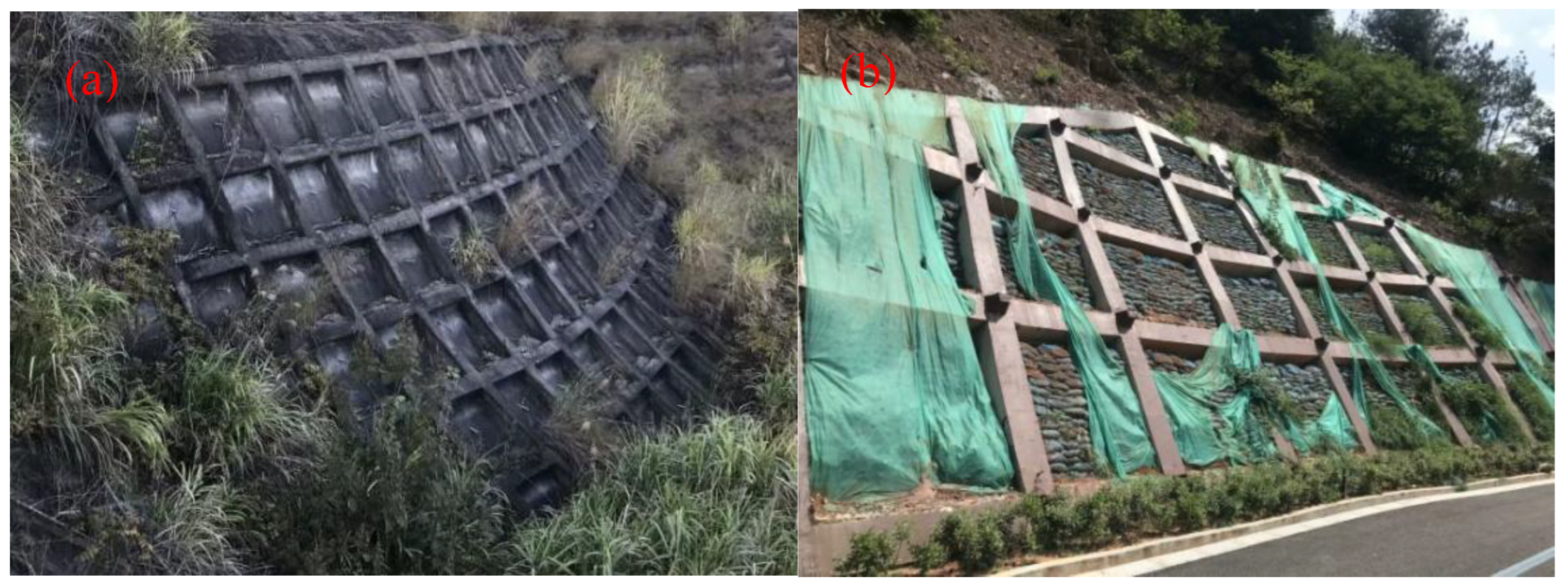
Figure 2.
Schematic Diagram of HPFB Slope Anchoring System.
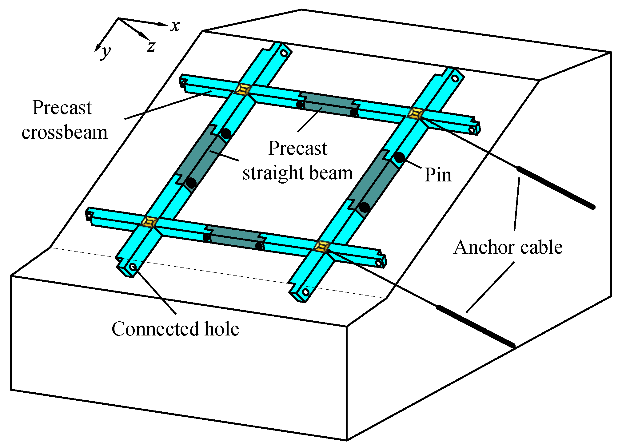
Figure 3.
Schematic Diagram of HPFB Structure.
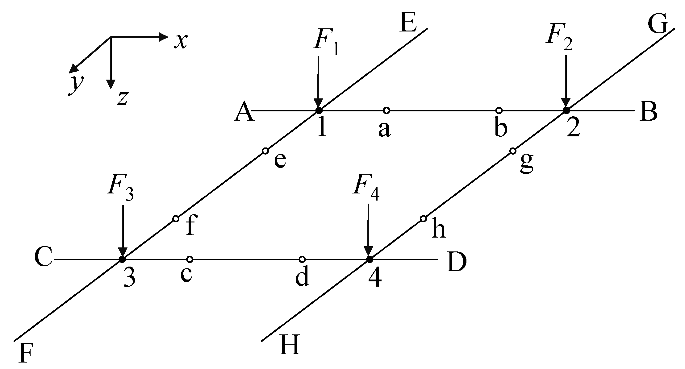
Figure 4.
Schematic diagram of disassembled horizontal and longitudinal beams under concentrated loads and beam-end shear forces: (a) horizontal beam AB; (b) horizontal beam CD; (c) longitudinal beam EF; (d) longitudinal beam GH.
Figure 4.
Schematic diagram of disassembled horizontal and longitudinal beams under concentrated loads and beam-end shear forces: (a) horizontal beam AB; (b) horizontal beam CD; (c) longitudinal beam EF; (d) longitudinal beam GH.
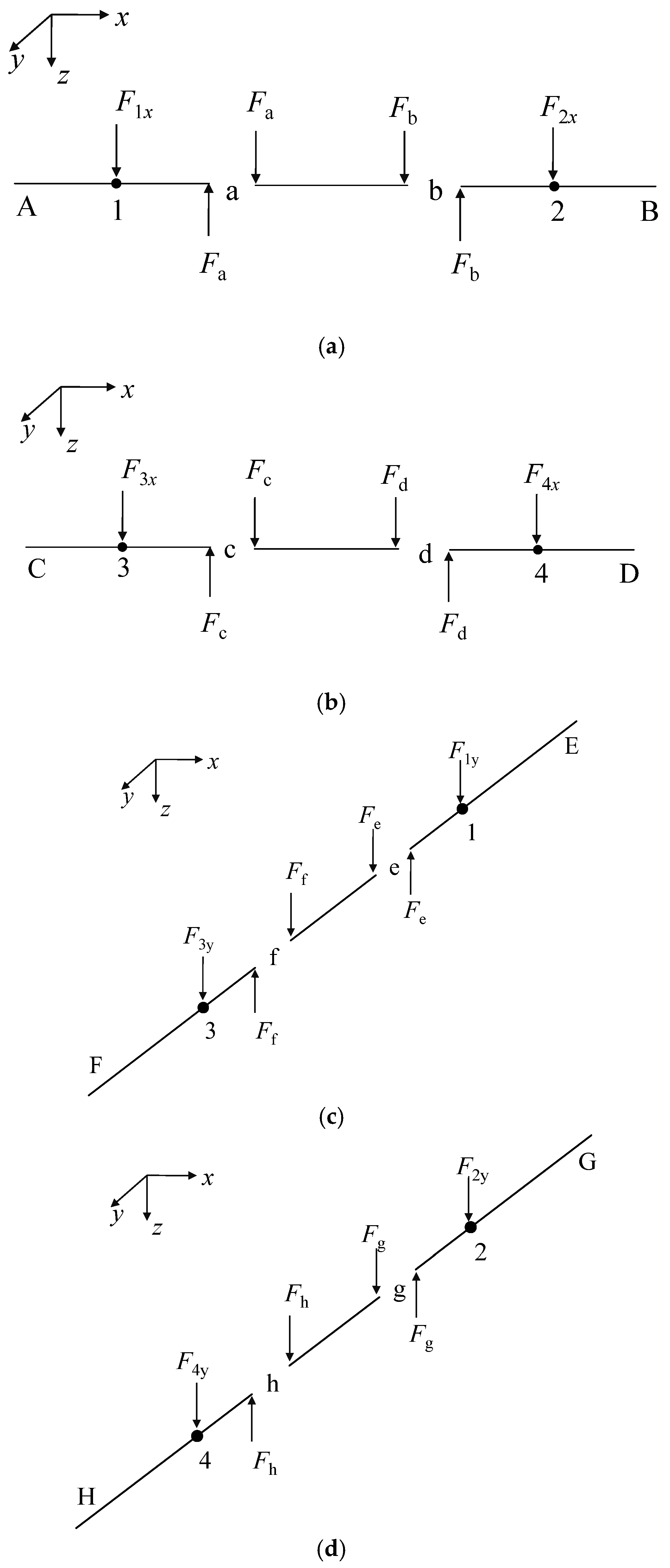
Figure 5.
Planar schematic diagrams of the two compared frame beam structures (unit: mm): (a) HPFB structure; (b) TFB structure.
Figure 5.
Planar schematic diagrams of the two compared frame beam structures (unit: mm): (a) HPFB structure; (b) TFB structure.
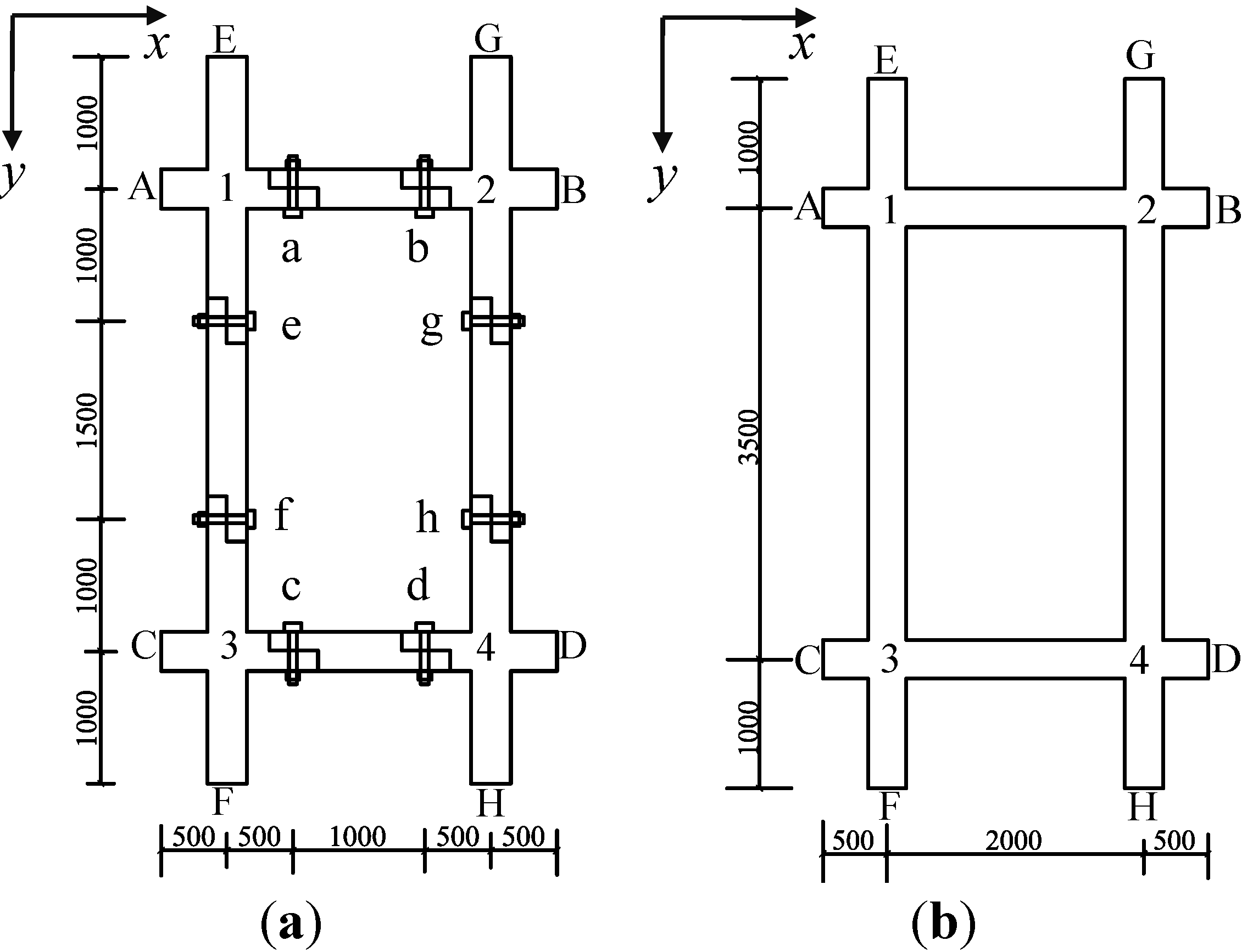
Figure 6.
Deflection curves of horizontal beam AB for both structures.
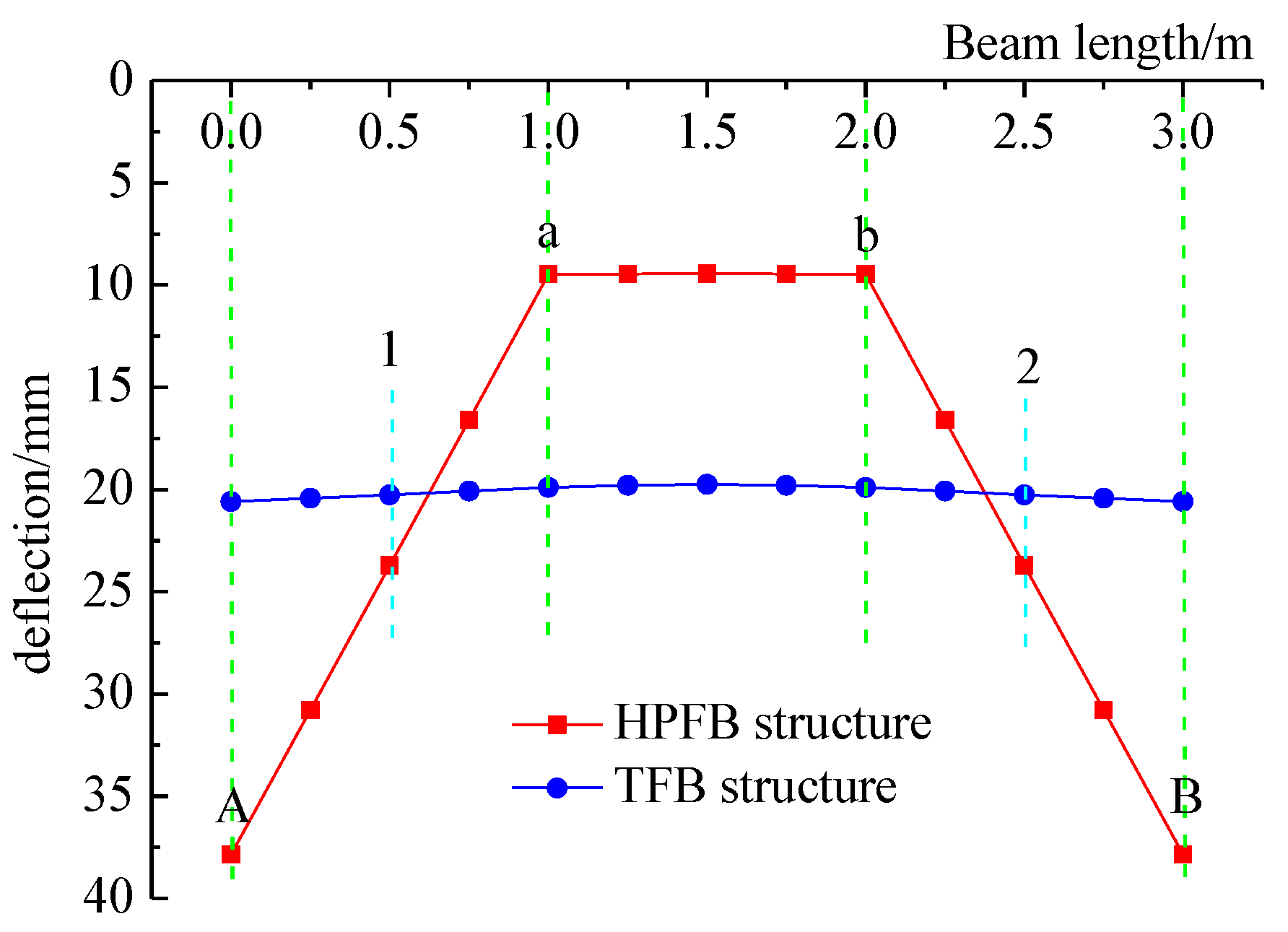
Figure 7.
Deflection curves of longitudinal beam EF for both structures.
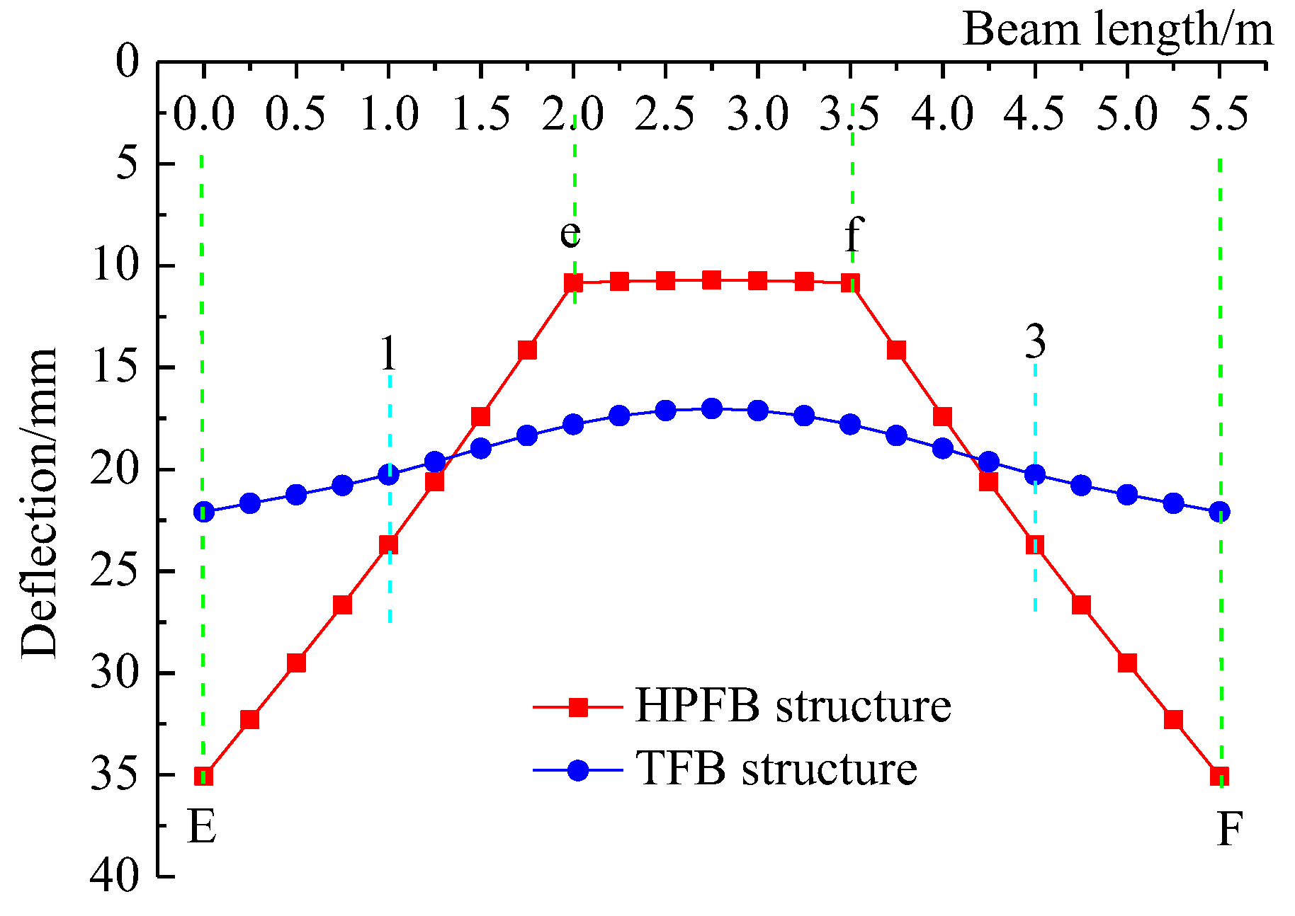
Figure 8.
Bending moment curves of horizontal beam AB for both structures.
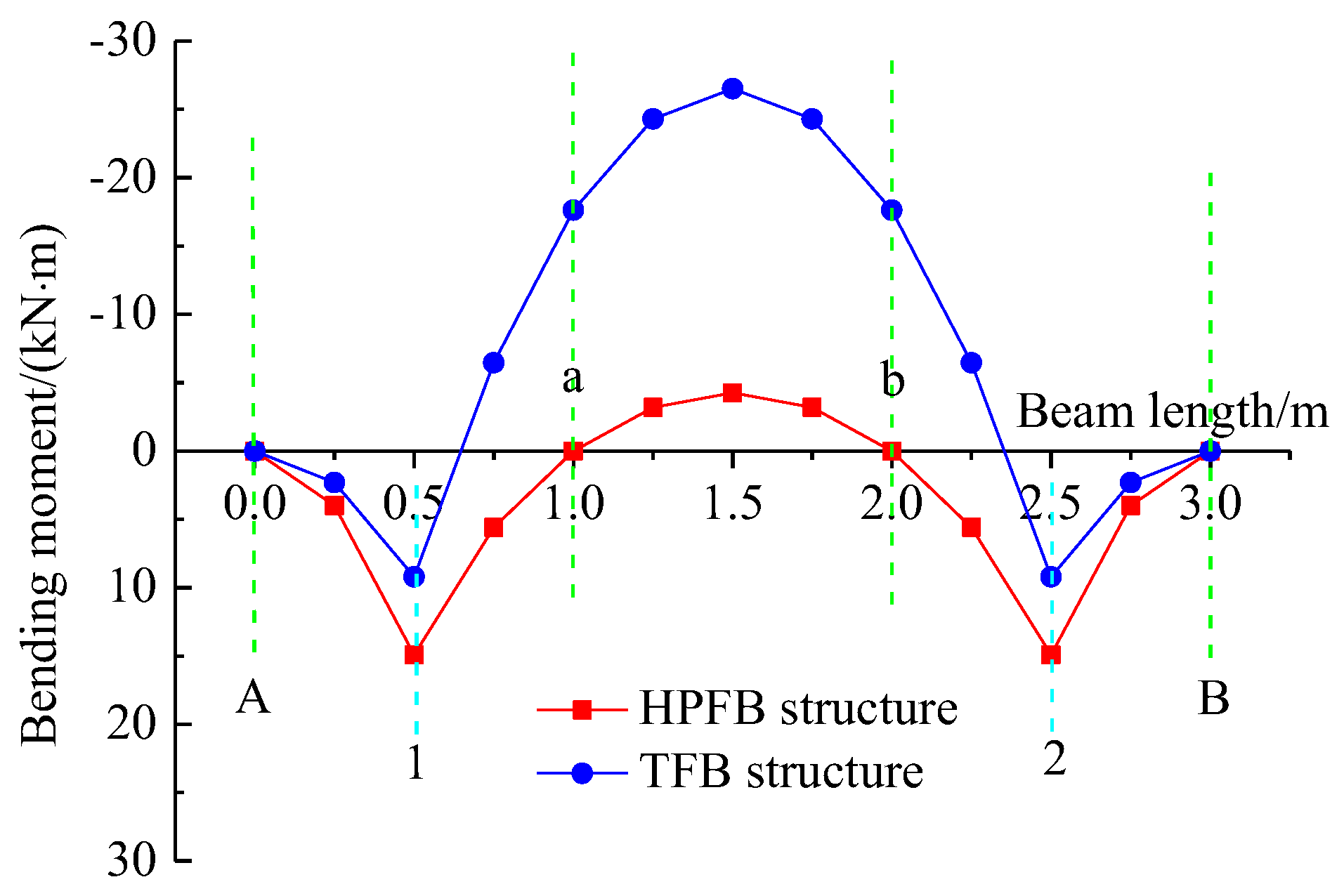
Figure 9.
Bending moment curves of longitudinal beam EF for both structures.
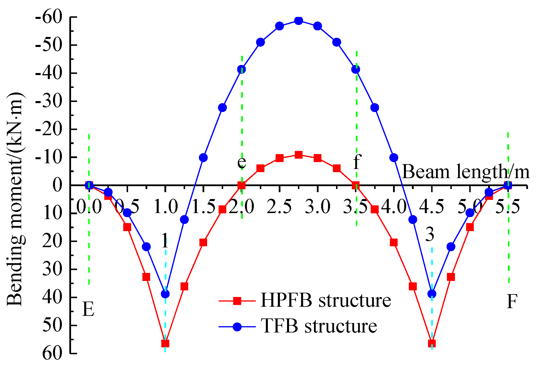
Figure 10.
Shear force diagrams of horizontal beam AB for both structures.
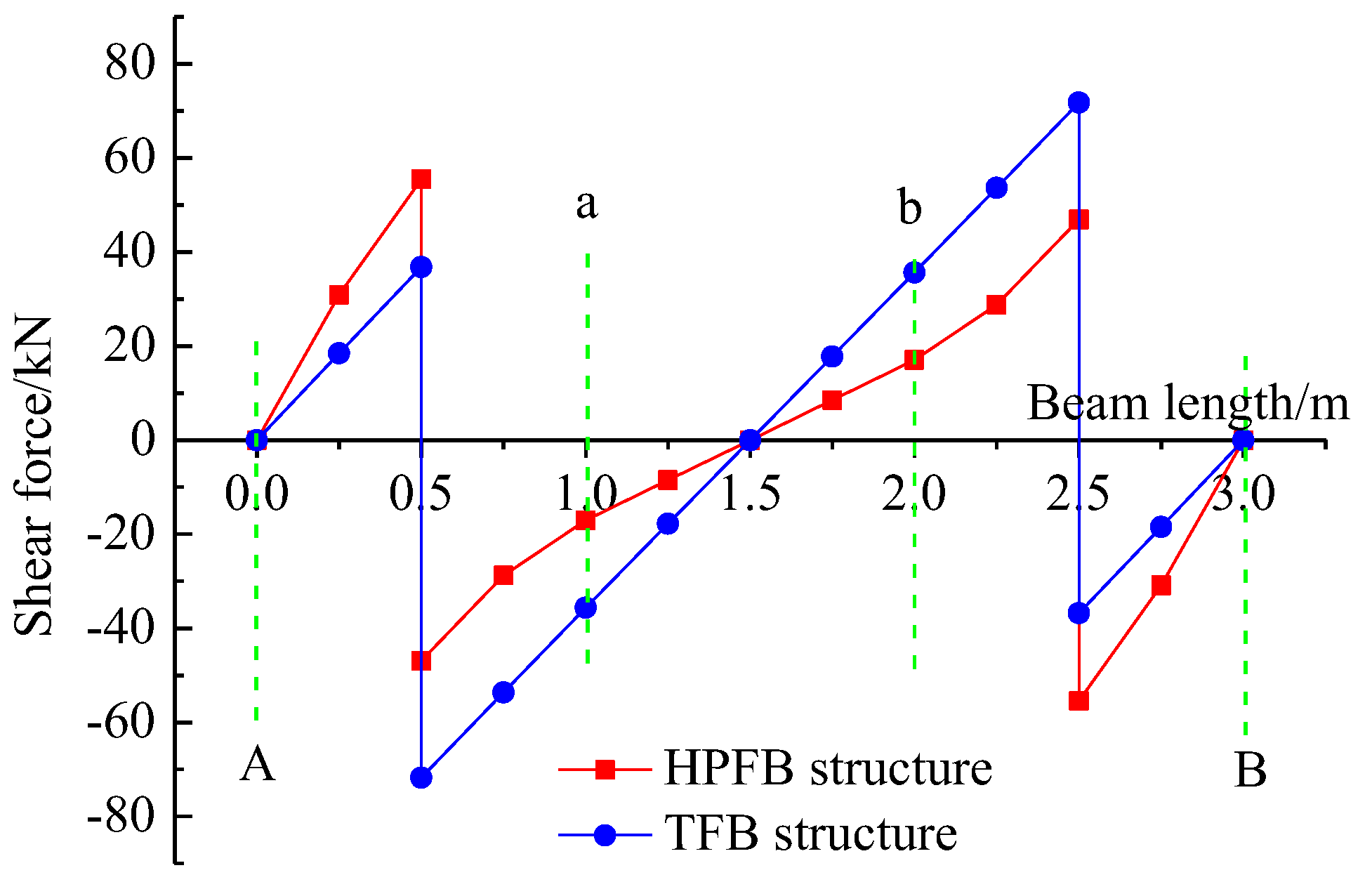
Figure 11.
Shear force diagrams of longitudinal beam EF for both structures.
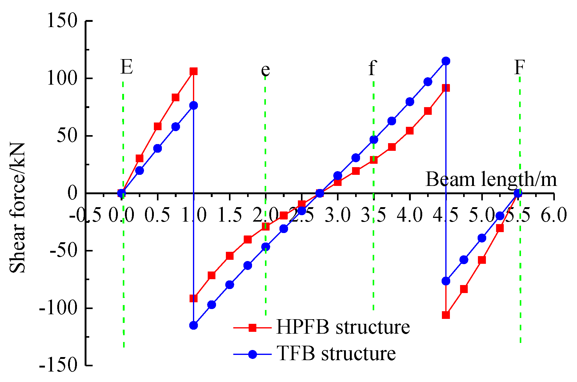
Figure 12.
Deflection Curves of Horizontal Beam AB to the Subgrade Reaction Coefficient.
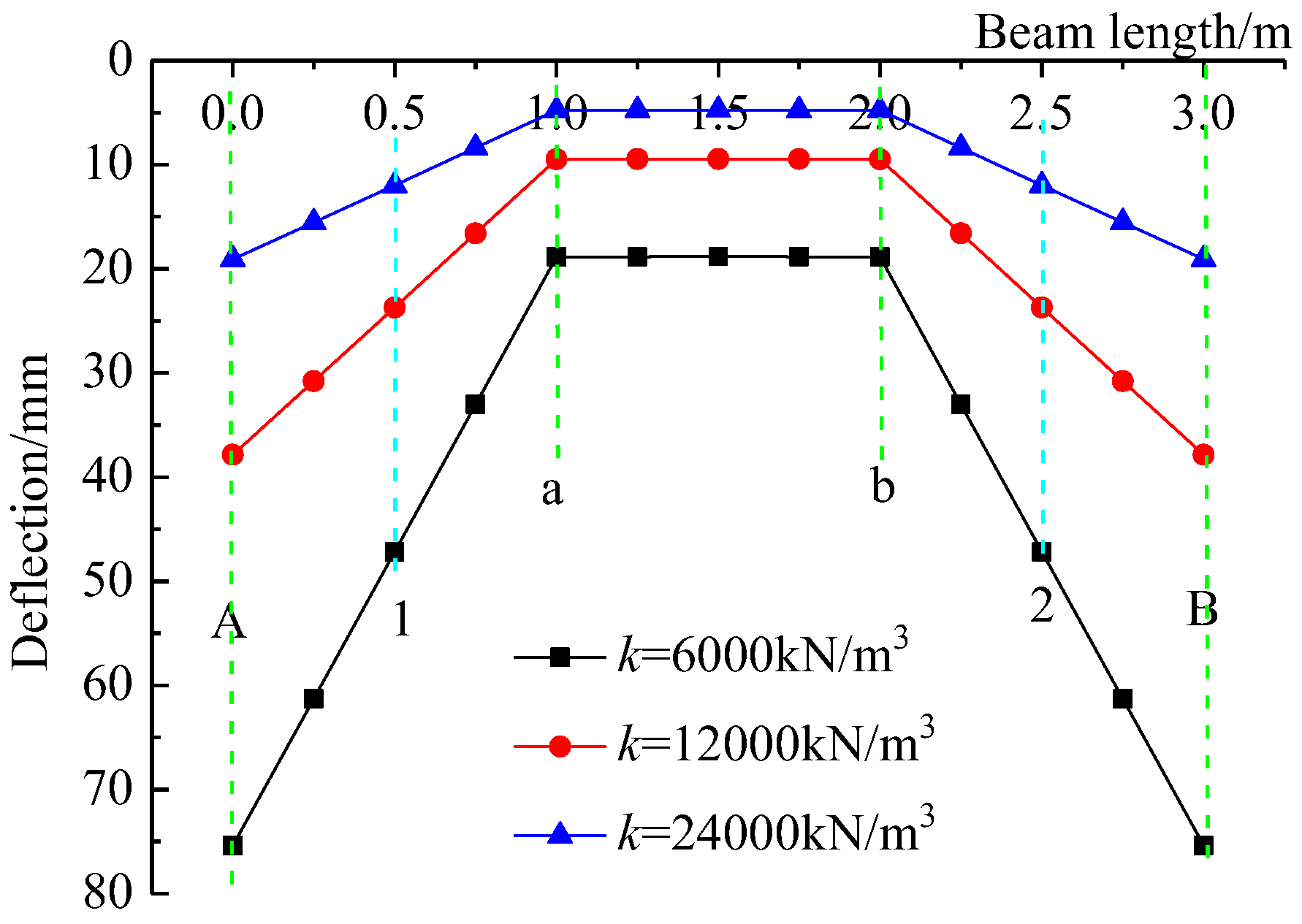
Figure 13.
Deflection Curves of Longitudinal Beam EF to the Subgrade Reaction Coefficients.
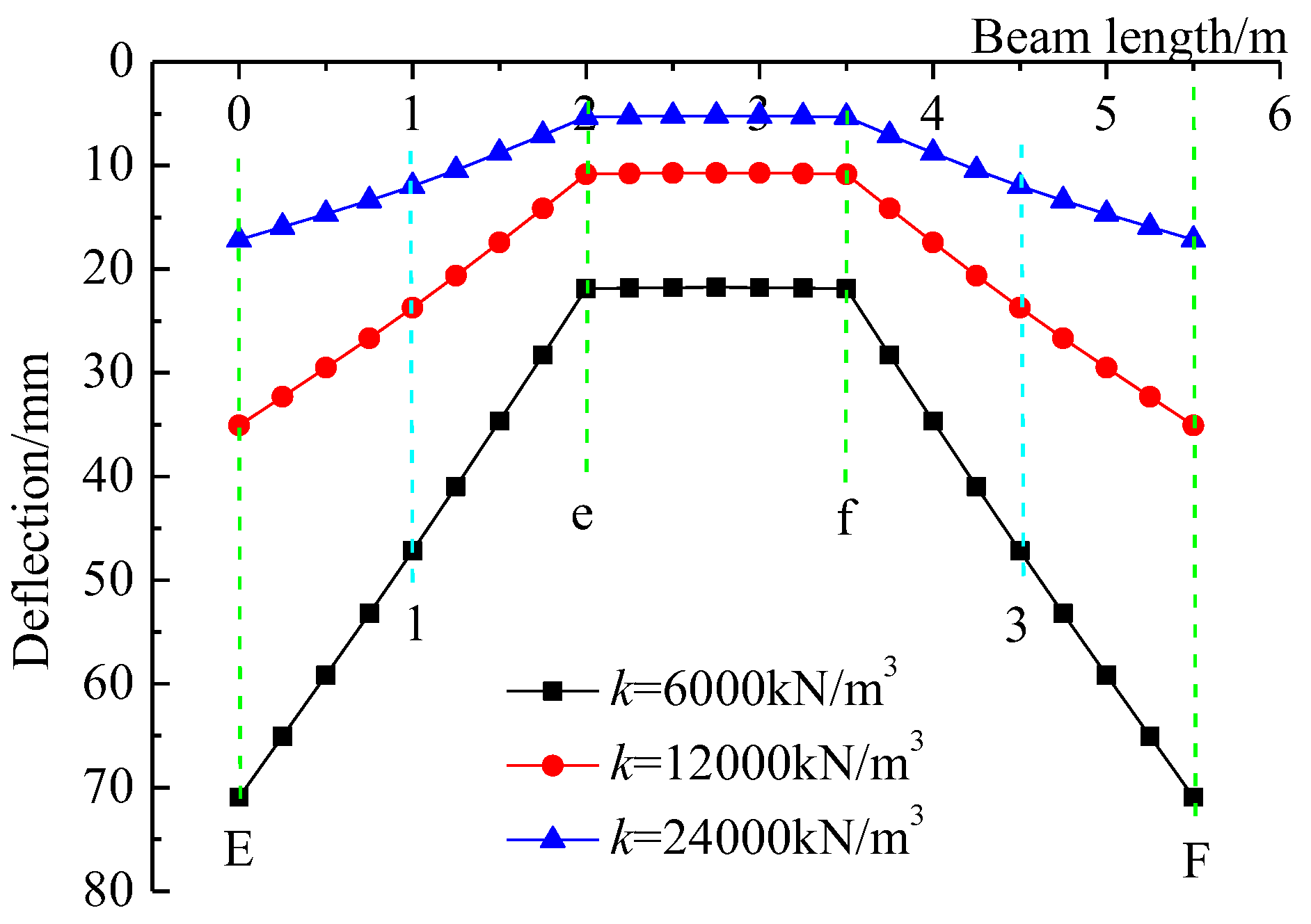
Figure 14.
Bending Moment Curves of Horizontal Beam AB to the Subgrade Reaction Coefficients.
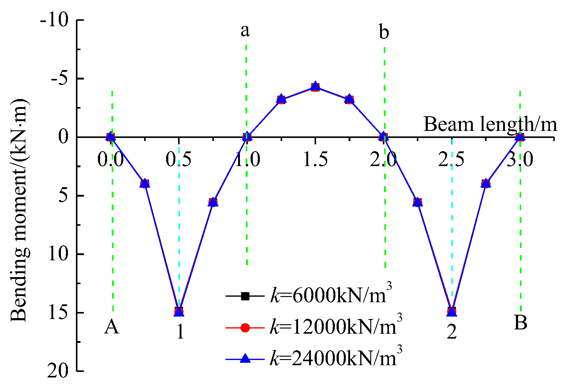
Figure 15.
Bending Moment Curves of Longitudinal Beam EF to the Subgrade Reaction Coefficients.
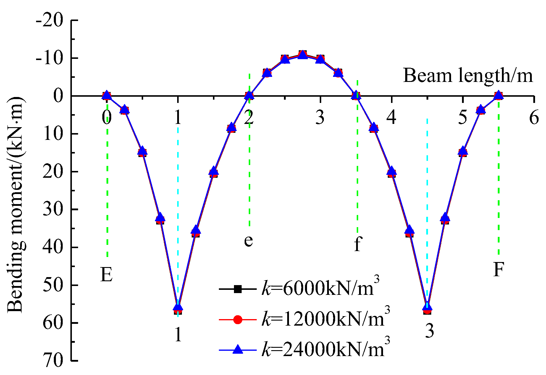
Figure 16.
Shear Force Curves of Horizontal Beam AB to the Subgrade Reaction Coefficients.
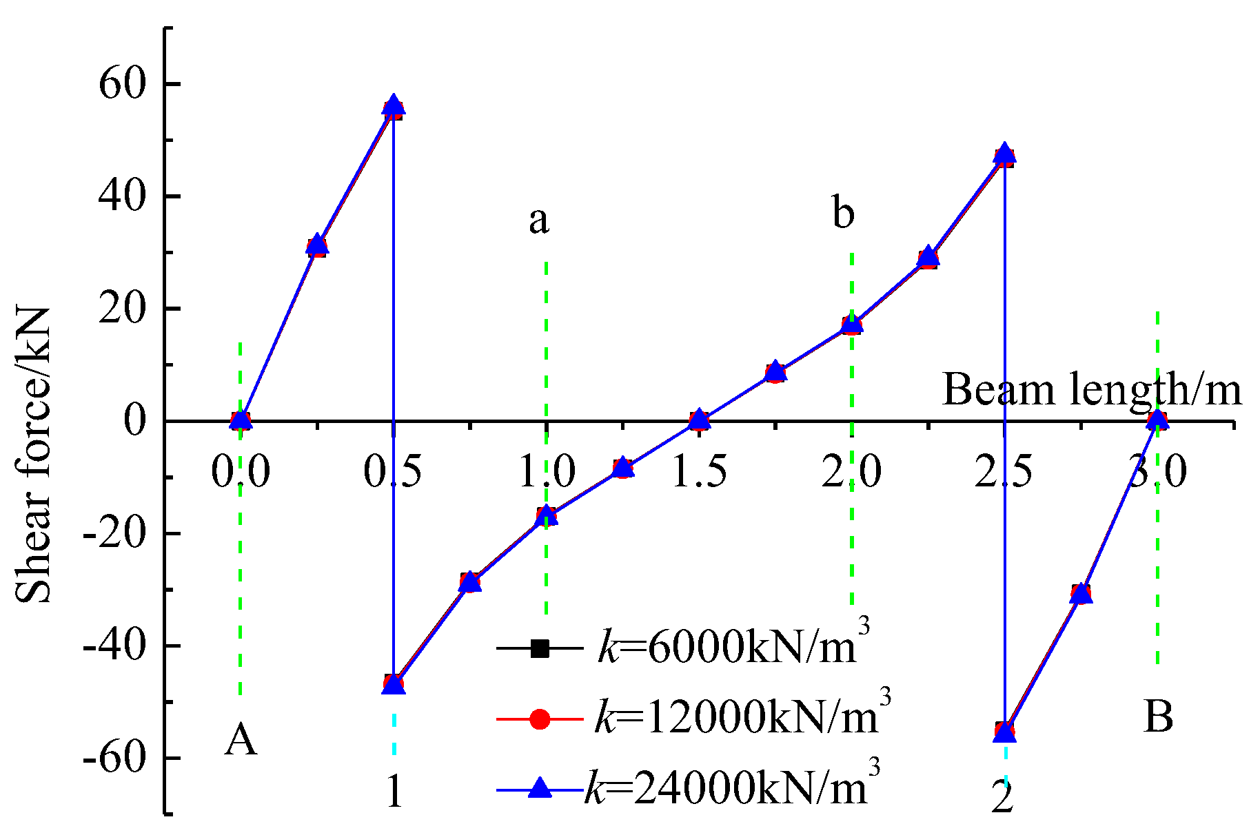
Figure 17.
Shear Force Curves of Longitudinal Beam EF to the Subgrade Reaction Coefficients.
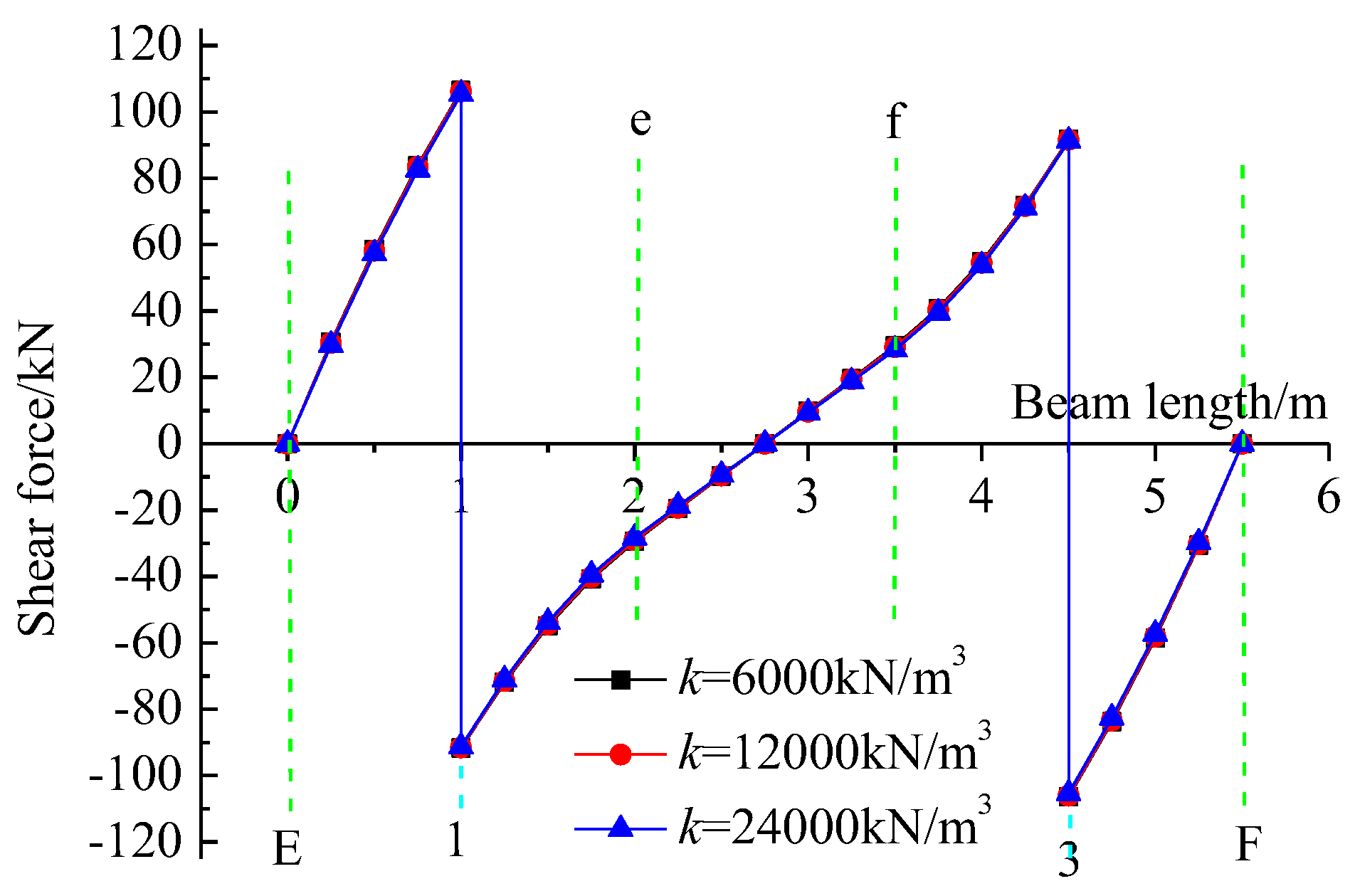

Table 1.
Load distribution and beam-end shear forces.
| Loads | HPFB Structure | TFB Structure |
| F1x/kN | 102.331 | 108.557 |
| F1y/kN | 197.699 | 191.443 |
| Fa/kN | 17.0278 | —— |
| Fe/kN | 29.0528 | —— |
Table 2.
Deflections of beam segments and horizontal/longitudinal beams.
| HPFB Structure | TFB Structure | ||||||
| w1x/mm | w1y/mm | waAa/mm | waab/mm | weEe/mm | weef/mm | w1x/mm | w1y/mm |
| 23.7151 | 23.7151 | 9.4738 | 9.4739 | 10.8409 | 10.8409 | 20.2595 | 20.2595 |
Table 3.
Load Distribution and Beam-End Shear Forces under Various Subgrade Reaction Coefficients.
| Loads | k=6000kN/m3 | k=12000kN/m3 | k=24000kN/m3 |
| F1x/kN | 101.833 | 102.331 | 103.305 |
| F1y/kN | 198.167 | 197.669 | 196.695 |
| Fa/kN | 16.9585 | 17.0278 | 17.1622 |
| Fe/kN | 29.4237 | 29.0528 | 28.3292 |
Table 4.
Comparison of key structural response ratios between this study and Zhang et al.
| Response Parameter | This study | Zhang et al. |
| Ratio of Maximum Negative Bending Moments | 16.0%-18.5% | 350% |
| Ratio of Maximum Positive Bending Moments | 146%-162% | 78.3% |
| Ratio of Maximum Shear Forces | 62.4%-77.2% | 114.3% |
Note: The ratios in the table represent the values of HPFB relative to TFB.
Disclaimer/Publisher’s Note: The statements, opinions and data contained in all publications are solely those of the individual author(s) and contributor(s) and not of MDPI and/or the editor(s). MDPI and/or the editor(s) disclaim responsibility for any injury to people or property resulting from any ideas, methods, instructions or products referred to in the content. |
© 2025 by the authors. Licensee MDPI, Basel, Switzerland. This article is an open access article distributed under the terms and conditions of the Creative Commons Attribution (CC BY) license (http://creativecommons.org/licenses/by/4.0/).
Copyright: This open access article is published under a Creative Commons CC BY 4.0 license, which permit the free download, distribution, and reuse, provided that the author and preprint are cited in any reuse.


