Submitted:
06 November 2025
Posted:
07 November 2025
You are already at the latest version
Abstract
This study presents an optimal bearing arrangement for the propulsion shafting system of ships equipped with multiple strut bearings, ensuring both structural stability and cost-effectiveness under shallow-draft conditions where the propeller must remain fully submerged. To this end, the shafting flexibility, alignment characteristics, and whirling vibration responses were analyzed for various bearing arrangements. The analysis results show that removing the stern tube bearing and supporting the shaft using only the Y-type and I-type strut bearings, with the bearing span adjusted so that the L/d ratio remains within 15 to 18, minimizes the reaction influence number, shaft bending moments, and variations in bearing loads. At this configuration, the first natural frequency corresponding to the propeller blade order is also more than 30 percent higher than the service speed, thereby avoiding resonance caused by transverse vibration. Accordingly, this study confirms that adjusting the layout of strut bearings can simultaneously enhance both the structural reliability and dynamic stability of the propulsion shafting system.
Keywords:
propulsion shafting system
; shaft alignment
; whirling vibration
; strut bearing
1. Introduction
Ships operating in coastal and nearshore waters are typically characterized by shallow drafts, which place the hull bottom in close proximity to the water surface. Under such conditions, the propeller may not be sufficiently submerged, leading to a significant loss in propulsion efficiency. To mitigate this limitation, shallow-draft ships are commonly equipped with externally mounted strut structures, such as Y-type or I-type struts, which support the propeller shaft at a greater depth below the hull. These struts not only enhance the submergence of the propeller but also ensure accurate shaft alignment, reduce vibration and wear, and improve the overall efficiency of power transmission. For this reason, strut-supported shafting systems are widely adopted in high-speed ships such as patrol boats, naval ships, and passenger ferries operating in constrained waterways [1,2,3,4]. In ships equipped with strut structures, the propulsion shafting system is typically configured with medium- to high-speed diesel engines or electric motors, along with reduction gear to decrease the rotational speed of the propeller. The propeller is connected to the propulsion engine via a single shaft, which is supported by seawater-lubricated bearings housed within the strut structures. Due to the relatively high shaft speed in proportion to the output power, the diameter of the propeller shaft is typically less than 400 mm. Shaft alignment analysis is not typically required for shafts with diameters less than 300 mm [5,6], and in some cases, even when the diameter is under 400 mm [7]. However, for propulsion shafting systems equipped with reduction gears, it is recommended that the bearing reaction forces supporting the gear shaft be reviewed during the design stage to prevent quality issues caused by shaft misalignment [5,6,7,8]. In such ships, the distance between the hull penetration point of the propeller shaft and the propeller is relatively long. To compensate for this extended span, a stern tube bearing may be installed. The number and position of bearings supporting the shaft determine the flexibility of the shafting system, making it necessary to select an appropriate bearing configuration during the initial design phase. The number and position of bearings supporting the shaft determine the flexibility of the shafting system, making it necessary to select an appropriate bearing configuration during the initial design phase. In this context, the primary objective of shaft alignment is to ensure that all supporting bearings receive acceptable loads throughout the ship’s operational life. Furthermore, each bearing should be subjected to acceptable load and stress levels, and the critical whirling speed must be kept sufficiently outside the operational speed range [8].
In the past, shafting systems were generally aligned in straight lines, with bearing locations determined based on tradition, symmetry, or ease of coupling arrangement. Reduction gears were installed in low positions to accommodate thermal expansion, and bearings adjacent to the propeller were bored at an angle to match the static deflection curve of the shaft, ensuring proper bearing contact [9]. In the 1950s, shafting problems caused by misalignment became apparent, which led to a more analytical approach that considered both uniformly distributed and concentrated loads, with bearing reaction forces calculated using the Hardy Cross moment distribution method. This development introduced the fair curve alignment theory [10,11,12], which assumes that the shaft follows a continuous curve from the engine to the propeller and that shaft deflection at bearing locations is zero. The theory has since served as the basis for bearing load and reaction calculations and remains widely applied in contemporary ship design.
Ships such as cruise ships and Ro-Pax ferries are traditionally designed with two or three struts supporting each propeller shaft [1]. The shaft is supported by multiple bearings, some located inside the struts and stern tube, and others placed as intermediate shaft bearings within the hull. At least one strut is required at the stern to support the heavy propeller. The number of required struts is determined by the number and arrangement of the shaft-supporting bearings, since each strut structure installed outside the hull is designed to support a bearing. Therefore, evaluating the number of struts requires considering both the quantity and positions of the supporting bearings. The number of bearings is primarily dictated by the combined weight of the shaft and propeller, as well as hydrodynamic forces generated by the propeller. Once the number of bearings is determined, their positions must be optimized. If bearings are placed too close to each other, the influence coefficients of bearing reactions may become excessively large, resulting in significant force imbalances between adjacent bearings. Generally, shaft system flexibility is defined by the distance(or span) between bearings and the diameter ratio of the shaft [13,14,15]. In large merchant ships, engine room volume is often minimized to maximize cargo capacity, leading to extremely small span-to-diameter ratios and complicating shafting layout design. In such cases, large influence coefficients may cause bearing loads to exceed design limits due to hull deflection or thermal expansion [16]. To overcome such limitations, an intermediate shaft bearing may be removed by partially modifying the engine room bulkhead, or the forward stern tube bearing may be removed and the intermediate bearing removed to afterward to improve shaft system flexibility [17,18]. However, excessive spacing between bearings can lead to resonance due to whirling vibrations. This may result in severe consequences, such as overheating and abnormal wear of the stern tube bearing, failure of the sealing system, and increased hull vibrations.
Recent research on propulsion shaft alignment has primarily focused on the factors influencing bearing reaction forces, alignment, and whirling vibration characteristics under various operational conditions. For instance, Zhou [19] identified bearing offset and angular misalignment as key parameters affecting bearing reaction and oil film pressure. Liao [20] proposed a laser-based alignment process modeled using a 4×4 homogeneous coordinate transformation matrix and experimentally verified its accuracy. Lei et al. [21] experimentally demonstrated that alignment adjustments significantly affect the ship’s vibration behavior and bearing temperature. In another study, Lei et al. [22] confirmed that misalignment has a greater impact on horizontal vibrations than. Wang et al. [23] developed a dynamic model of a dual-rotor system and analyzed the system behavior under combined unbalance and misalignment, finding that such conditions produce high-order harmonic components at integer multiples of the rotational speed.
Low et al. [24] analyzed the effects of hull deflection during vessel operation on the alignment and positioning of the propulsion shafting system and proposed an alignment method considering hull deflection. Lu et al. [25] categorized various uncertainties affecting propulsion shafting system and suggested probabilistic finite element methods and non-parametric modeling approaches. Seo et al. [26] used finite element analysis on a 300,000 DWT VLCC to assess hull deflection and shaft bearing displacement under varying draft conditions. Tuckmantel et al. [27] investigated the influence of rotor–coupling–bearing interactions on vibration signals in rotating systems with angular misalignment. Gomez et al. [28] investigated the influence of crack location on shaft diagnostics, proposing a method using third harmonic energy variation for crack detection. Vuong et al. [29] experimentally analyzed the impact of operating conditions on whirling vibration in hybrid propulsion systems.
This study presents an optimal bearing arrangement for propulsion shafting systems supported by multiple strut bearings, aiming to ensure structural stability and economic feasibility under dynamic loading conditions, particularly in shallow-draft ships that require deeper propeller submersion.
To achieve this, the study was divided into two phases and each phase focused on a distinct analytical objective. The first phase involved evaluating shaft flexibility for different bearing arrangements and performing shaft alignment analysis based on the structural characteristics of the ship where bearings are installed. This analysis was used to identify bearing configurations that are less sensitive to internal and external forces acting on the propulsion shafting system. The second phase involved conducting whirling vibration analysis to avoid resonance caused by excitation from the propeller blade frequency. Based on this analysis, the optimal bearing positions were determined so that the natural frequency associated with the blade passing order remains outside the ±30 percent range of the operational speed.
This study is expected to serve as a valuable design guideline for optimizing the number and placement of bearings supporting the propulsion shaft, enhancing shaft system flexibility and stability under various operational conditions in vessels equipped with traditional multiple strut bearings.
2. Theoretical Analysis Method
2.1. Shaft Alignment Analysis Theory
Theoretical approaches commonly used for analyzing bearing reaction forces in shaft alignment include the Three-Moment Method, the Transfer Matrix Method, and the Matrix Structural Analysis method based on the Finite Element Method [10,11,12,15,18,30,31]. In this study, the Matrix Structural Analysis method, which is widely applied for evaluating the behavior of complex structural systems, was adopted.
Generally, the propulsion shafting system is modeled as a laterally loaded, non-uniform beam. As illustrated in Figure 1, the shaft is discretized into small elements, and for each element, local stiffness matrices and external force vectors are derived to formulate the nodal equilibrium equations. The resulting nodal equation for the shaft system is expressed as Eq.1.
In this equation, the first vector on the right-hand side represents the external forces applied at the nodes, while the second vector contains the fixed-end forces of each element, converted from intermediate loads into equivalent nodal forces. The coefficient matrix on the left-hand side corresponds to the global stiffness matrix of the shaft. By solving Eq.1 for the nodal displacements, from Uₚ₁ to Uₚ₄, the nodal displacements can be obtained. The equation can be simplified into the form of Eq.2 and then rearranged to isolate the internal force vector f, as shown in Eq.3. into equivalent nodal forces. The coefficient matrix on the left-hand side corresponds to the global stiffness matrix of the shaft. By solving Eq.1 for the nodal displacements, from Uₚ₁ to Uₚ₄, the shaft deflection can be obtained. The equation can be simplified into the form of Eq.2 and then rearranged to isolate the internal force vector f, as shown in Eq.3.
The inverse of the stiffness matrix K becomes the flexibility matrix, and by multiplying both sides of Eq.2 by, Eq.4 is obtained. From Eq.4, the nodal displacements can be determined. Since bearing reaction forces constitute a part of the external force vector P, the unknown bearing loads can be evaluated by substituting the results of Eq.4 into Eq.3.
The inverse of the stiffness matrix K becomes the flexibility matrix, and by multiplying both sides of Eq.2 by, Eq.4 is obtained. From Eq.4, the nodal displacements can be determined. Since bearing reaction forces constitute a part of the external force vector P, the unknown bearing loads can be evaluated by substituting the results of Eq.4 into Eq.3.
When the vertical height of a bearing is changed by 1.0 mm, the resulting variation in the reaction force at adjacent bearings is defined as the Reaction Influence Number (RIN). Lowering the height of one bearing increases the loads on neighboring bearings, and this redistribution continues progressively until a new equilibrium is reached. This indicates that each bearing has an associated influence coefficient corresponding to a unit vertical displacement. A larger coefficient implies that the shafting system is more sensitive to alignment errors. The relationship between bearing reaction forces and RIN can be expressed in matrix form as shown in Eq.5.
Accordingly, the state analysis of a shafting system involves discretizing the shaft into finite elements, computing the stiffness matrix for each element, and assembling these into the global stiffness matrix. By displacing each bearing vertically by a unit height of 1.0 mm, the resulting bearing loads are compared with those obtained under the reference condition where all bearings are aligned. The difference between these two results provides the Reaction Influence Number. Based on these influence coefficients, the allowable bearing height offsets can be determined such that the resulting bearing reaction forces remain within permissible limits. In addition, the bending moment and shear force at each node are evaluated, and the corresponding stresses are calculated.
2.2. Whirling vibration analysis theory
Analytical methods for evaluating the whirling vibration of propulsion shafting systems can be categorized into approximate and precise methods. Approximate approaches include the Panagopoulos equation, the modified Panagopoulos equation, the Jasper equation, and the Jasper–Rayleigh equation, while precise methods consist of the Transfer Matrix Method and the Finite Element Method (FEM) [15,18,32,33,34,35,36]. In the present study, the modified Panagopoulos and Jasper–Rayleigh equations were adopted as approximate methods, and FEM was used as the precise method due to its wide application in whirling vibration analysis.
The modified Panagopoulos equation assumes that the shaft is fixed at the rearmost intermediate bearing, neglecting the support provided by the forward stern tube bearing. Therefore, in the vibration model, only the aft stern tube bearing is considered as a support. As illustrated in Figure 2, the propeller is mounted at point A, and the shaft is simply supported at points B and C. Considering moment equilibrium about point B leads to Eq. 6, and the corresponding natural frequency is obtained by Eq.7.
The Jasper–Rayleigh equation assumes that the shaft is supported at the afterward stern tube bearing and fixed at the rearmost intermediate bearing. Various influence coefficients are evaluated by applying unit forces and moments at the propeller. Using these coefficients, the vibration equation is derived as Eq.8, and the natural frequency is expressed in Eq.9.
To calculate the natural frequency, the equivalent mass of the shaft must be added to the propeller mass. In addition, hydrodynamic added mass effects must be taken into account. Fifteen percent of the in-air propeller mass is added to represent the surrounding water. Twenty-five percent of the in-air polar moment of inertia is added to account for the hydrodynamic inertia. Sixty percent of the in-air propeller mass is added to the moment of inertia associated with the propeller diameter.
In the finite element method, the shaft is divided into multiple elements, with the mass of each element split in half and concentrated at adjacent nodes. As a result, the shafting system is composed of lumped masses connected by massless elastic shafts. For each divided element, the relationships between stress and strain and between force and displacement are derived.
Figure 3 represents the end forces, moments, displacements, and angular deflections in both the X–Y and X–Z planes. These relationships are established using Castigliano’s theorem and Maxwell–Betti’s reciprocal theorem. The orthogonal relationships for a flexible shaft under whirling vibration in the X–Y and X–Z planes are expressed in Eq. 10, and its matrix form is shown in Eq. 11. In this equation, {F} denotes the force column matrix, {K} is the stiffness matrix, and {U} represents the displacement column matrix.
When two beam elements, i and i+1, are connected at a common node n, as illustrated in Figure 4, displacement and rotation must be continuous across this node in both planes. The equilibrium conditions at node n are given by Eq.12.
The end forces and moments for each element are expressed in terms of nodal displacements and rotations based on the stiffness matrices of adjacent elements. These equations for all nodes are assembled into a global matrix form, as represented by Eq. 13.
In this equation, {M} is the global mass matrix, {K} is the global stiffness matrix, {y} is the displacement vector, and {f} is the force and moment vector at each node. For free vibration, {}=ω2 and {f}=0, which transforms the equation into the eigenvalue problem expressed in Eq. 14. Solving this equation provides the natural frequencies and their corresponding mode shapes.
3. Configuration Characteristics of the Propulsion Shafting System in the Subject Ship
Figure 5 represents the propulsion shafting arrangement of the subject ship, and the detailed specifications are summarized in Table 1 and Table 2. The propeller shaft is supported by two strut bearings located outside the hull and one stern tube bearing inside the hull. All three bearings are seawater-lubricated Thordon-type bearings. The ship is powered by a 1,029 kW four-stroke diesel engine. A single-stage reduction gear with a reduction ratio of 5.05 is installed at the output side of the engine. Through the reduction gear, the maximum power is delivered to the propeller at 415.8 rpm. The propeller consists of four blades, has a diameter of 1.65 m, and weighs 429.7 kg including the propeller cap. The propeller shaft has a diameter ranging from 190 mm to 195 mm and a total length of 7,737 mm. Unlike typical arrangement, the subject ship does not incorporate an intermediate shaft, resulting in a relatively long propeller shaft with respect to its diameter. The gearwheel shaft of the reduction gear is supported by tapered roller bearings, which can withstand both axial and radial loads.
Due to the shallow draft, a Y-type and an I-type strut are installed externally to ensure complete submergence of the propeller, while a stern tube is installed internally. A total of three Thordon bearings are fitted into these two struts and the stern tube to support the propeller shaft. An assessment of shaft flexibility reveals that the section supported by the two strut bearings exhibits sufficient lateral flexibility, with an L/d ratio of 19.3. However, for the remaining segments, the L/d ratios are 8.6 and 8.2 respectively, which fall below the generally accepted design criterion of 14.0.
It is generally recognized that the minimum span between bearings should be twelve times the shaft diameter when the shaft diameter exceeds 400 mm, and at least fourteen times for diameters below 400 mm [15,18]. In the subject ship, the portion of the shaft supported by the I-type strut and stern tube fails to satisfy these criteria. As a result, the reaction influence number of the bearings may become excessively high, increasing the sensitivity of the shafting system to hull deflection and thermal expansion of bearing structures. This can lead to difficulties in shaft alignment and significant changes in bearing loads after adjustment.
To address these limitations, a redesign of the bearing arrangement is required to enhance the flexibility of the propulsion shafting system.
4. Analysis Results and Disccussion
This study presents an optimized propulsion shafting arrangement for conventional ships equipped with multiple strut bearings operating under shallow draft conditions. The objective is to enhance the flexibility and stability of the propulsion shafting system across various operating conditions and to determine the optimal number and placement of shaft-supporting bearings. To this end, the number and positions of bearings supporting the propeller shaft were selectively modified.
The two tapered roller bearings supporting the reduction gear shaft were excluded from the scope of design changes, as these components are typically fixed during the early design phase. The Y-type strut bearing was also retained without modification due to its critical role in supporting the heavy propeller in demanding operating conditions. Therefore, this study focused on modifying the I-type strut bearing and the stern tube bearing to improve shafting flexibility.
To increase the flexibility of the shafting system, the spacing between shaft and supporting bearings was enlarged. As summarized in Table 3, the proposed arrangement involved removing either the I-type strut bearing or the stern tube bearing. Additionally, the positions of the bearings were moved afterward in increments corresponding to the ship’s frame spacing, considering the structural constraints of the hull.
In Case I, the I-type strut bearing was removed, and the stern tube bearing was positioned at Frame 13, as shown in Figure 6. In Case II, the stern tube bearing was removed while the I-type strut bearing was retained and relocated afterward in increments of one frame, as shown in Figure 7. Due to the fixed structure of the stern tube, the bearing position in Case I could not be changed and was analyzed only at a single location. In contrast, Case II allowed positional flexibility, and the I-type strut bearing was incrementally moved afterward. The frame spacing in the subject ship is 520 mm.
An essential consideration in propulsion shafting system design is to ensure sufficient transverse flexibility so that bearing reaction forces are not overly sensitive to displacement variations. Figure 8 presents the design procedure for determining an optimal propulsion shafting arrangement. From the initial design phase, the L/d ratio (bearing span to shaft diameter) should be evaluated to secure adequate shafting flexibility. The span between the two primary supporting bearings must exceed an L/d value of 4.8, and all other spans between adjacent bearings should exceed L/d = 12.0. For shafts with diameters below 400 mm, a minimum value of L/d = 14.0 is recommended.
After configuring a straight shafting layout, shaft alignment analysis is performed to evaluate the reaction influence number (RIN) of each bearing. Based on this analysis, the bearing height (offset) is adjusted during the fair curve alignment stage so that all bearing reaction forces remain positive. The final stern tube bearing must be installed with an inclined bore to accommodate the propeller weight. The relative slope between the bearing and the shaft must be maintained within 3.0mrad, where the relative slope is defined as the angular difference between the bearing inclination and the shaft axis.
Following the alignment evaluation, a whirling vibration analysis is conducted for each proposed arrangement. This ensures that resonance induced by the blade passing frequency is avoided within the operating speed range of the propulsion shafting system.
4.1. Analysis of shafting flexibility
Figure 9 represents the variation in shafting flexibility resulting from changes in the design parameters listed in Table 4. In Case I, the removal of the I-type strut bearing extends the span between the Y-type strut bearing and the stern tube bearing to 5,068 mm, corresponding to an L/d ratio of 26.7. This value indicates sufficient whirling flexibility. However, an excessively long bearing span may reduce the natural frequency of the shafting system and increase the risk of resonance occurring within ±30 percent of the operational speed. If such resonance occurs, it may cause critical failures such as abnormal wear or overheating of the stern tube bearing, damage to the sealing system, and leakage of stern tube lubricant.
Due to structural constraints, the stern tube bearing is fixed at Frame 13 inside the hull. Consequently, the span between the stern tube bearing and the afterward gearbox bearing cannot be adjusted. The corresponding L/d ratio is 8.2, which is below the generally accepted criterion for whirling flexibility. This limitation prevents improvement in flexibility for that section of the shaft.
In Case II, the stern tube bearing is removed, and the I-type strut bearing is repositioned. Owing to the structural characteristics of the strut foundation, the I-type strut bearing can be moved between Frames 9 and 13, as indicated by the parameter variations in Table 4. The analysis shows that placing the I-type strut bearing at Frame 11 results in L/d ratios of 14.1 and 21.2 in the respective shaft sections, both of which exceed the minimum design criterion of 14.0.
From the standpoint of shafting flexibility, Case II provides a more favorable bearing arrangement. However, to ensure that the L/d ratio does not become excessively large, which may cause resonance due to whirling vibration, the bearing location should be limited to between Frames 9 and 11. The final bearing configuration must be selected based on the combined results of shaft alignment analysis and whirling vibration analysis to secure both structural flexibility and dynamic stability.
4.2. Shaft Alignment Characteristics
The objective of shaft alignment is to ensure that all shaft-supporting bearings are subjected to permissible loads and stresses throughout the ship’s operational life. To determine the optimal bearing arrangement, the Reaction Influence Number (RIN) must be evaluated under straight alignment conditions. This evaluation allows for the identification of shafting arrangements that exhibit low sensitivity to misalignment. RIN serves as an indicator of shafting system flexibility. High RIN values are associated with stiff systems that are highly sensitive to misalignment, while low RIN values correspond to more flexible arrangements capable of maintaining stable bearing loads and reduced bending stresses under alignment deviations.
Table 4 represents the RIN values for each bearing under the bearing arrangement cases shown in Figure 6 and Figure 7, based on the design parameter variations outlined in Table 3. The listed RIN values represent the diagonal components of the RIN matrix obtained from shaft alignment analysis in the straight arrangement.
The results indicate that as the I-type strut bearing is removed afterward, the RIN of the Y-type strut bearing increases, while the RINs of the I-type strut bearing and the gearbox bearings gradually decrease. When the I-type strut bearing is placed at Frame 9 or 10, the variation in RIN exceeds 30 percent compared to its preceding positions. Conversely, the RIN values for the I-type strut bearing and the gearbox bearings decrease by less than 20 percent.
These findings suggest that placing the I-type strut bearing at Frame 10 or 11 results in a shafting configuration that exhibits improved flexibility and greater robustness against alignment errors.
After identifying the bearing arrangement that minimizes RIN values under the straight alignment condition, a fair curve alignment analysis is conducted. This analysis determines the vertical offset required at each bearing to ensure positive reaction forces under actual operating conditions.
Figure 10 represents the variation in offset between the two gearbox bearings for each design parameter case. The results show that as the I-type strut bearing is moved afterward, the required vertical offset between the gearbox bearings increases to maintain positive reactions throughout the shafting system.
Cold static condition refers to a stationary state in which the propeller is fully submerged and thermal effects are not considered. Hot static condition includes thermal expansion effects. Hot dynamic condition accounts for both thermal effects and the bending moment induced by eccentric rotation of the shaft. According to DNV classification guidance [8], the torque variation in this condition is assumed to be ±30 percent of the maximum torque.
Under static conditions, the weight of the propeller predominantly increases the loads on the two strut bearings, with minimal impact on the gearbox bearings. However, under dynamic conditions, the load distribution shifts due to the bending moment, resulting in increased loads on the stern tube and gearbox bearings.
With respect to the position of the I-type strut bearing, under static conditions, afterward movement of the bearing decreases the load on the two strut bearings while increasing the load on the aft gearbox bearing. Under dynamic conditions, such movement reduces the loads on both the strut and aft gearbox bearings slightly, while increasing the load on the forward gearbox bearing.
These variations indicate that Cases III and IV exhibit the most stable distribution of bearing loads across all operating conditions.
In terms of shaft deformation behavior, afterward movement of the I-type strut bearing reduces the bending moment between the two strut bearings. However, in Case V, the increased bearing span causes the bending moment to rise again, indicating a loss of structural balance.
In conclusion, Case IV provides the most effective shafting configuration in terms of alignment characteristics. The bearing reactions remain well-distributed across all support points, and the bending moment is minimized, ensuring reliable performance in both structural and operational contexts.
4.3. Whirling Vibration Characteristics
Resonance between the natural frequencies of whirling vibration, caused by unbalanced rotating mass, and the operational shaft speed is recognized as a principal cause of propulsion shafting system failures. These failures include damage to the stern tube sealing system, abnormal wear of the stern tube bearing, and leakage of lubricating oil [30,31]. To prevent such resonance, the DNV classification society recommends that the first natural frequency of whirling vibration maintains a design margin of at least 30 percent above the service rotational speed [8]. This requirement is particularly critical for ships such as the one examined in this study, which features a long bearing span and a high shaft rotational speed. Proper consideration must be given during the design phase to ensure resonance does not occur.
The whirling vibration characteristics were evaluated for the shafting arrangement shown in Figure 6 and Figure 7, using the design parameter variations presented in Table 4. Approximate methods based on the Panagopoulos and Jasper–Rayleigh equations were used, in addition to the finite element method (FEM), which is widely used for precise analysis of transverse vibrations.
Table 6 and Table 7 provide the natural frequencies obtained from the analysis, while Figure 13 illustrates the mode shapes derived from the FEM results. As the I-type strut bearing is moved aft, the first natural frequency associated with the blade passing order of the propeller increases. However, simplified calculations using the Jasper–Rayleigh equation show that in all cases the first natural frequency remains within ±30 percent of the service speed, which is 415.8 rpm. Only Case I, when analyzed using the Panagopoulos method, satisfies the DNV criterion by achieving a 31.1 percent margin.
The FEM results, which are considered more accurate for complex shafting systems, show a different trend. When the I-type strut bearing is placed in the Case I position, the first blade passing frequency is 431.9 rpm, corresponding to only a 3.9 percent margin. This does not satisfy the classification requirement and indicates a risk of resonance.
Therefore, the bearing position must be revised to avoid potential failures.
According to Table 7, positioning the I-type strut bearing at the Case III or Case IV positions results in a natural frequency of 554.4 rpm, providing a 33.0 percent margin above the service speed. In contrast, Case V shows a reduced natural frequency of 478.9 rpm, which brings the system closer to the resonance range again.
This behavior is attributed to the increased span between the I-type strut bearing and the afterward gearbox bearing, as shown in Figure 9. The resulting unsupported length of the shaft increases the possibility of local whirling resonance. This may cause problems such as seal failure, gear wear, or excessive structural vibration and noise. Therefore, the afterward position of the I-type strut bearing should not exceed the location defined in Case IV.
The Panagopoulos and Jasper–Rayleigh equations assume the shaft is simply supported at two points, as represented in Figure 2. The vibration shape is approximated by the static deflection curve under a constant bending moment at the propeller. Due to these simplifications, such methods are inadequate for systems with multiple external strut bearings.
In a previous study, whilring vibration characteristics were analyzed for a 50K DWT product tanker [18]. The study showed that natural frequencies predicted using simplified equations were slightly higher than those obtained by FEM. However, in this study, the FEM-based results are approximately 27.1 to 33.9 percent higher than the values predicted by the simplified methods.
Given this discrepancy, although the Panagopoulos and Jasper–Rayleigh equations offer convenience in the early design stages, they may produce significantly distorted results for propulsion shafting systems with multiple strut bearings. Therefore, it is strongly recommended to use FEM for accurate prediction of natural frequencies in such cases.
5. Conclusion
This study investigated an optimal bearing arrangement for the propulsion shafting system of ships equipped with multiple strut bearings, targeting both dynamic stability and cost-effectiveness under operational loading conditions. The subject ship operates in shallow waters, requiring deeper submergence of the propeller. Accordingly, various bearing arrangements were analyzed to evaluate shafting flexibility, alignment characteristics, and whirling vibration behavior, considering structural constraints at each bearing position. The major findings are as follows.
The existing arrangement showed that the shaft segment supported by two strut bearings had sufficient transverse flexibility, with an L/d ratio of 19.3. However, other segments exhibited L/d ratios of 8.6 and 8.2, significantly below the recommended threshold of 14.0. These low L/d values resulted in excessive Reaction Influence Numbers (RINs), making the system vulnerable to hull deflection and thermal expansion of the bearing supports. Such conditions complicate alignment adjustments and may lead to significant load redistributions after alignment. Therefore, redesigning the bearing layout is necessary to enhance system flexibility.
To address this issue, a bearing arrangement was proposed in which the span between shaft-supporting bearings is increased. In Case I, where the I-type strut bearing was removed, the remaining supports (Y-type strut and stern tube bearings) were insufficient for flexibility improvement due to the fixed installation position of the stern tube bearing within the hull.
Alternatively, removing the stern tube bearing while retaining both strut bearings enabled positional adjustment of the I-type strut bearing. Cases III through V, in which the L/d ratio exceeded 14.0, demonstrated significantly improved flexibility. However, overly large L/d ratios may lower the natural frequencies of the shaft and increase the risk of resonance. Thus, the final arrangement must be determined by combining alignment and whirling vibration analysis.
Shaft alignment analysis under straight configuration showed that the minimum RIN values were achieved when the I-type strut bearing was located at Cases III and IV. Fair-curve alignment and multi-condition operating conditions indicated that afterward movement of the I-type strut bearing reduced the load on strut bearings when the ship was stationary but slightly increased the load on the forward gearbox bearing during operation. Bending moment analysis showed that further aft movement generally reduced the bending between the two strut bearings, though excessive movement (Case V) led to increased bending again. Overall, Case IV provided the most balanced bearing loads and minimal bending moment.
Whirling vibration analysis using the finite element method revealed that in Case I, the first natural frequency associated with the blade passing order was 431.0 rpm, only 3.9 percent above the service speed of 415.8 rpm, which does not satisfy the 30 percent margin recommended by DNV. In contrast, Cases III and IV yielded a natural frequency of 554.4 rpm, securing a sufficient margin of 33.0 percent and thereby avoiding resonance. Case V showed a reduction in frequency to 478.0 rpm, again approaching resonance, attributed to local resonance in the shaft segment between the I-type strut bearing and aft gearbox bearing where the L/d ratio reached 19.5.
In summary, for ships with multiple strut bearings, the optimal bearing layout should exclude the stern tube bearing and support the propeller shaft using two strut bearings. The I-type strut bearing should be placed in a position that minimizes RIN values and maintains stable bearing loads and bending behavior under both static and dynamic conditions. Furthermore, the bearing position must ensure that the first natural frequency exceeds the service speed by at least 30 percent to avoid whirling resonance. For the subject ship, this optimal arrangement is achieved by placing the I-type strut bearing at the position defined in Case III or IV, which ensures both structural reliability and economic efficiency during operation.
Funding
This work was supported by a grant from the National R&D project of “Development of the fuel gas supply system for a hydrogen fuel engine (RS-2024-00430798)” funded by Ministry of Trade, Industry and Energy, South Korea. All supports are gratefully acknowledged.
Abbreviations
| DWT | Deadweight |
| RIN | Reaction influence number |
| PCT | Product chemical tanker |
| POT | Product oil tanker |
| COT | Crude oil tanker |
| VLCC | Very large crude oil carrier |
| MB | Main bearing |
| FR. | Frame |
| P1 ~ P4 | External force acting on a node |
| UP1 ~ UP4 | Displacement of nodes |
| ffa1 | Section force at a1 stage |
| K | Stiffness matrix |
| U | Displacement row matrix |
| P | External force row matrix |
| f | Section force row matrix |
| F | Force row matrix |
| R | Bearing load after alignment |
| Initial bearing load | |
| [M] | Total mass matrix |
| [K] | Total stiffness matrix |
| Moment of inertia of propeller (kgm2) | |
| Moment of inertia about propeller diameter (kgm2) | |
| Distance between forward and afterward stern tube Bearing (mm) | |
| Distance between forward stern tube bearing and intermediate shaft bearing (mm) | |
| Diameter of propeller shaft (mm) | |
| Diameter of intermediate shaft (mm) | |
| Force to be applied to a1 point in order to cause unit displacement at a1 point | |
| Force to be applied to b1 point in order to cause a unit displacement at a1 point | |
| Natural frequency (cpm) | |
| Height variation in bearing | |
| m | Propeller mass (kg) |
| Mass per unit length of shaft (kg) | |
| Natural frequency by panagopulos method (cpm) | |
| Equivalent mass of shaft (kg) | |
| p | Natural frequency by jasper-rayleigh method (cpm) |
| Propeller angular velocity | |
| Deflection when a unit force is applied to the tip of the propeller | |
| Angle of deflection when a unit force is applied to the tip of the propeller | |
| Angle of deflection when a unit moment is applied to the tip of the propeller |
References
- Rivera Maritime Media, Propeller shaft bearing layout is better with fewer struts, https:// www.rivieramm.com/news-content-hub/news-content-hub/propeller-shaft-bearing-layout-is-better-with-fewer-struts-51649, 2008. (Accessed 2 April 2025).
- H.S. Seol, J.W. Ahn, Y.H. Park, B.G., Paik, H.S. Jeong, Improvement of ship propeller cavitation inception speed by changing the alignment angle of the inclined shaft support strut, Journal of defense quality society, Vol. 4, No.2, (2022), 116-123.
- H.J Lee, H.S. Jang, H.H. Chun, Study on the shaft-strut design in the initial design stage, Journal of the society of naval architecture of korea, Vol. 41, No.6 (2004) 114-119. [CrossRef]
- M.G. Park, Y. K. Shin, Study on the design of shaft strut for naval ships with twin screw, Journal of the Korean society of marine environment & safety, Vol.8, No.1 (2002) 81-87.
- ABS, Rules for building and classing: Marine vessels Part 4 vessel systems and machinery, https://ww2.eagle.org/en/rules-and-resources/rules-and-guides-v2.html, 2025 (Accessed 5 April 2025).
- Bureau Veritas, Rules for the classification of steel ships: Part C Machinery, electricity, automation and fire protection, https://marine-offshore.bureauveritas.com /rules-guidelines, 2025 (Accessed 5 April 2025).
- Korean Register, Rules for the classification of steel ships: Part 5 Machinery installations Annex 5-12 Shaft alignment, https://www.krs.co.kr/KRRules/KRRules 2025/KRRulesE.html, 2025 (Accessed 5 April 2025).
- Det Norske Veritas AS, Rules for the classification of ships: Part 4 Chapter 4 Rotating machinery-power transmission, https://www.dnvgl.com/rules-standards /index.html, 2016 (Accessed 5 April 2025).
- R.E. Kosiba, J.J. Francis, R.A. Woolacott, The alignment of main propulsion shaft bearings in ships, SNAME, New England Section Paper, 1956. [CrossRef]
- G. Mann, Design of propulsion shaft systems using fair curve alignment theory, The American Society of Naval Engineers Journal, Vol.76, No.6 (1964) 851-862.
- G. Mann, Analysis of shafting problem using fair curve alignment theory, The American Society of Naval Engineers Journal, Vol.77, No.1 (1965)117-133. [CrossRef]
- G. Mann, Shipyard alignment of propulsion shafting using fair curve alignment theory, Naval engineers’s Journal, Vol.77, No.4 (1965) 651-659. [CrossRef]
- Z. Mourelatos, P. Papalambros, A mathematical mode for optimal strength and alignment of marine shafting system, Journal of ship research, Vol.29, No.3 (1985) 212-222. [CrossRef]
- O. C. Larsen, Some consideration on marine shafting design, Industrial lubrication and tribology, Vol.33, No.5 (1981) 164-171. [CrossRef]
- Korean Register, Control of ship vibration, Third edition, Textbook publisher, Seoul, 2012 (in Korean).
- Class NK, Guidelines on shafting alignment, Class NK, Tokyo, 2006.
- J.R. Kim, “Lateral vibration and shaft alignment on the propulsion shafting system”, Journal of the Korean society of marine engineering, Vol. 27, No.2 (2003) 198-208 (in Korean).
- Y.G. Kim, U.K. Kim, Design and analysis of the propulsion shafting system in a ship with single stern tube bearing, Journal of marine science and technology, Vol.25, No.2 (2020) 536-548. [CrossRef]
- W. Zhou, Y. Zhao, H. Yuan, X. Wang, Study of the hull structural deformation calculation using the matrix displacement method and its influence on the shaft alignment . Journal of marine science and engineering Vol.11 No.8 (2023) 1495. [CrossRef]
- T.T. Liao, Modeling and analysis of laser shaft alignment using 4 x 4 homogeneous coordinate transformation matrix, Measurement, Vol.42 (2009) 147-163. [CrossRef]
- J. Lei, R. Zhou, H. Chen, G. Huang, Y. Gao, Q. Yang, Effects of ship propulsion shafting alignment on whirling vibration and bearing temperature response, Mathematical problems in engineering, (2021) 1-10. [CrossRef]
- J. Lei, R. Zhou, H. Chen, G. Huang, Y. Gao, G. Lai, Experimental investigation of effects of ship propulsion shafting alignment on shafting whirling and bearing vibrations, Journal of marine science and technology, Vol.27 (2022) 151-162. [CrossRef]
- N. Wang, D. Jiang, Vibration response characteristics of a dual-rotor with unbalance-misalignment coupling faults Theoretical analysis and experimental study, Mechanism and machine theory, Vol.125 (2018) 207-219. [CrossRef]
- K. H. Low, S.H. Lim, Propulsion shaft alignment method and analysis for surface crafts, Advances in engineering software, Vol.35 (2004) 45-58. [CrossRef]
- L. Lu, G. Li, P. Xing, H. Gao, Y. Song, A review of stochastic finite element and nonparametric modelling for ship propulsion shaft dynamic alignment, Ocean engineering, Vol.286 (2023) 1156656. [CrossRef]
- C.O. Seo, B.U. Jeong, J.R. Kim, M.H. Song, J.H. Noh, J.U. Lee, Determining the influence of ship hull deformations. [CrossRef]
- F.W.D.S Tuckmantel, K. L. Cavalca, Vibration Vibration signatures of a rotor-coupling-bearing system under angular misalignment, Mechanism and machine theory, Vol.133 (2019) 559-583. [CrossRef]
- M.J. Gomez, C. Castejon, E. Corral, J.C. Garcia-Prada, Analysis of the influence of crack location for diagnosis in rotating shafts based on 3 x energy, Mechanism and machine theory, Vol.103 (2016) 167-173. [CrossRef]
- Q.D. Vuong, Y.M. Kim, K.H. Seo, H.J. Choi, H. N. Truong, J.W. Lee, J.U. Lee, An experimental study on the dynamic behavior of propulsion shafting alignment in a hybrid vessel, Ocean engineering, Vol.299 (2024) 117389. [CrossRef]
- D.H. Moon, H. J. Jeon, A study on the propulsion shaft alignment calculation by the matrix method of three-moment theory, Journal of the Korean Society of Marine Engineering, Vol.5 No.1 (1981) 1-8 (in Korean).
- H. J. Jeon, H. G. Park, H. S. Choi, Optimum alignment of marine engine shafting by the finite element method, Journal of the Korean Society of Marine Engineering, Vol.2 No.1 (1978) 1-14 (in Korean).
- Y. Hori, M. Tanaka, A. Hasuike, T, Nasuda, Lateral vibrations of propeller shaft systems, Bulletin of the M.E. S. J., Vol.6 No.4 (1977), 338-344.
- E. Panagopulos, Design stage calculation of torsional, axial and lateral vibration of marine shafting, Transactions of society of naval architects and marine engineers, Vol. 58 (1950) 329-384.
- N. H. Jasper, All experimental and theoretical investigation of propeller shaft failures, Transactions of society of naval architects and marine engineers, Vol. 50 (1952) 314-381.
- N.H. Jasper, A theoretical approach to the problem of critical whirling speeds of shaft-desk systems, DTMB report 890, David taylor model basin, United States of America, 1954. [CrossRef]
- N. H. Jasper, A design approach to the problem of critical whirling speeds of shaft-desk systems”, DTMB report 890, David taylor model basin, United States of America, 1954. [CrossRef]
Figure 1.
Non-uniform section beam.
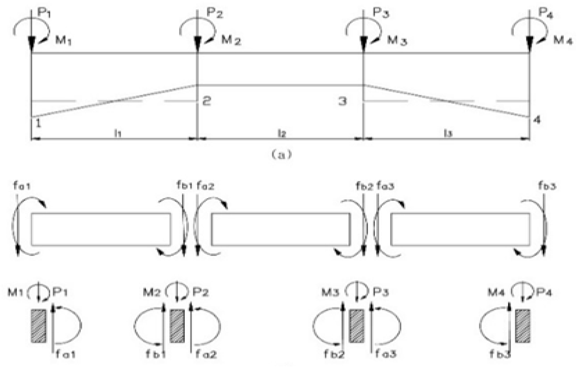
Figure 2.
Equivalent model of the modified Panagopoulos equation.
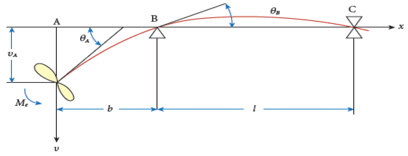
Figure 3.
End force, moment, displacement and whirling angle in beam element.
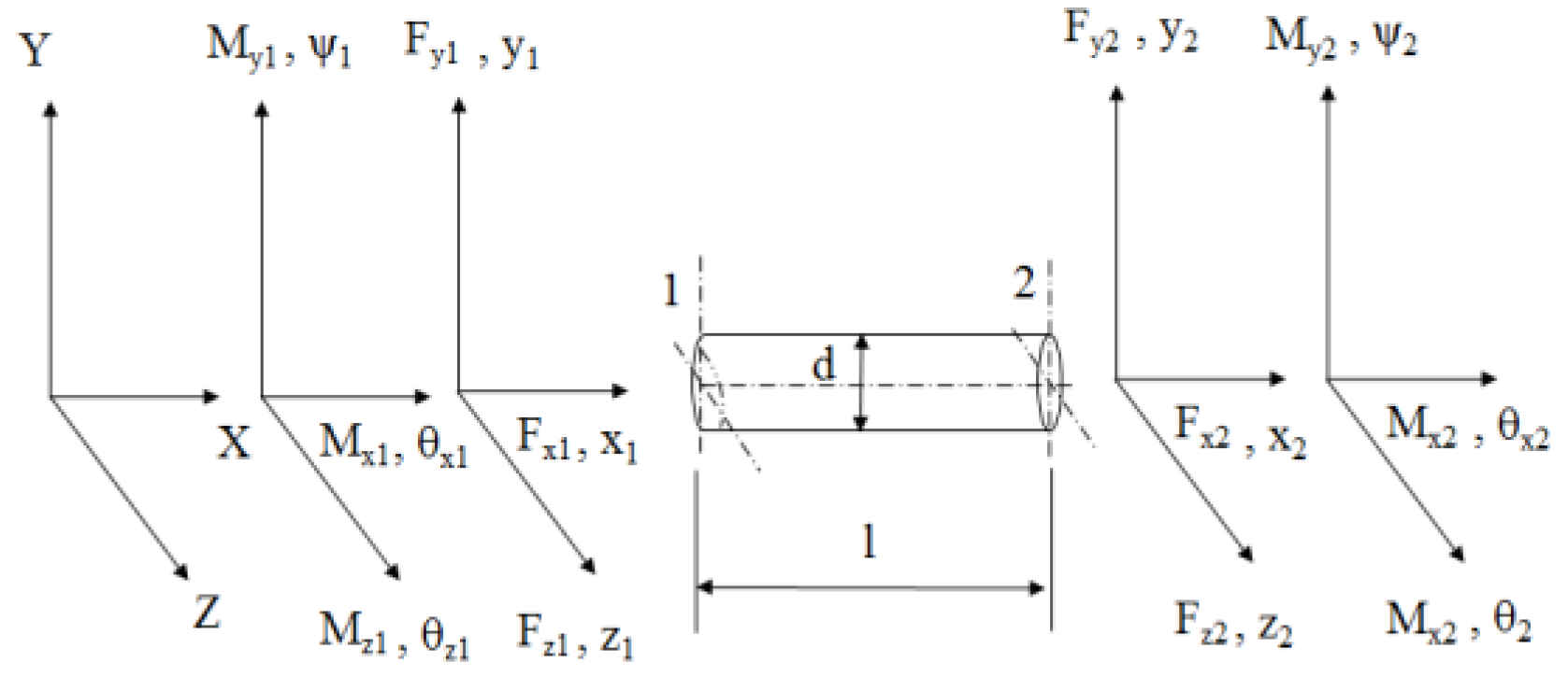
Figure 4.
Relationship between adjacent elements of mass point n: (a) Mass point n on X-Y plane; (b) Mass point n on X-Z plane.
Figure 4.
Relationship between adjacent elements of mass point n: (a) Mass point n on X-Y plane; (b) Mass point n on X-Z plane.
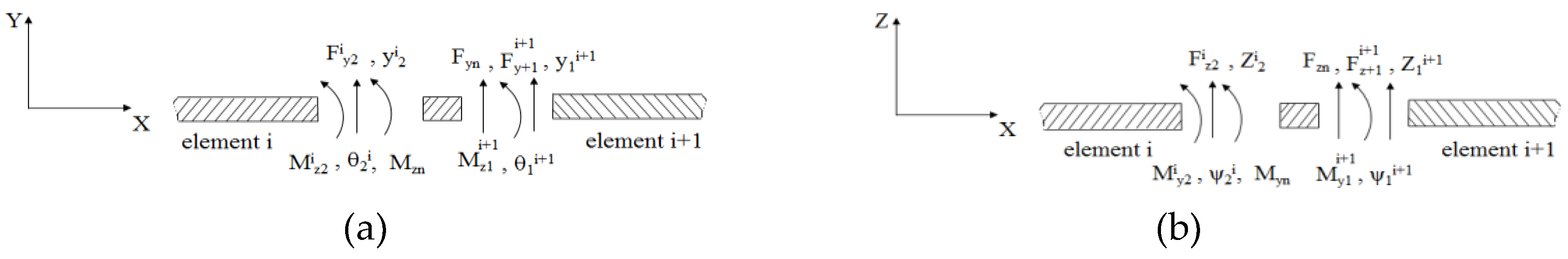
Figure 5.
Arrangement of the conventional propulsion shafting system with multiple strut bearings.
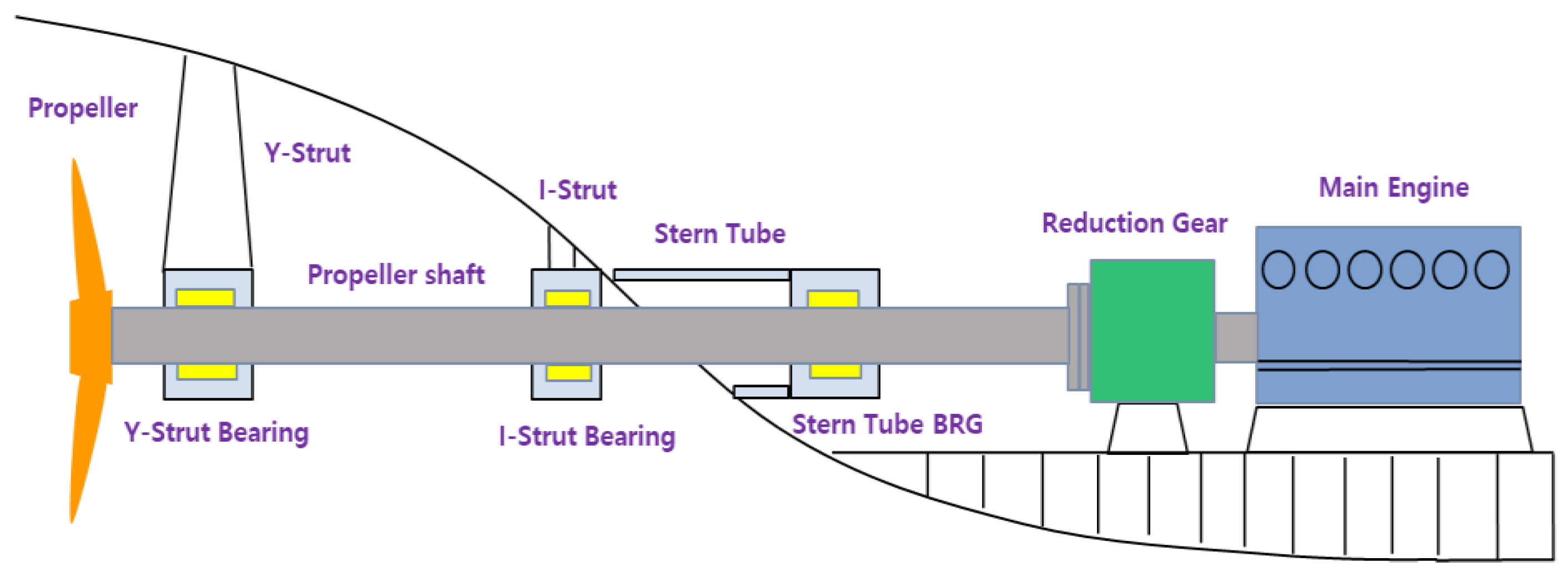
Figure 6.
Arrangement of the propulsion shafting system without I strut bearing (Case Ⅰ).
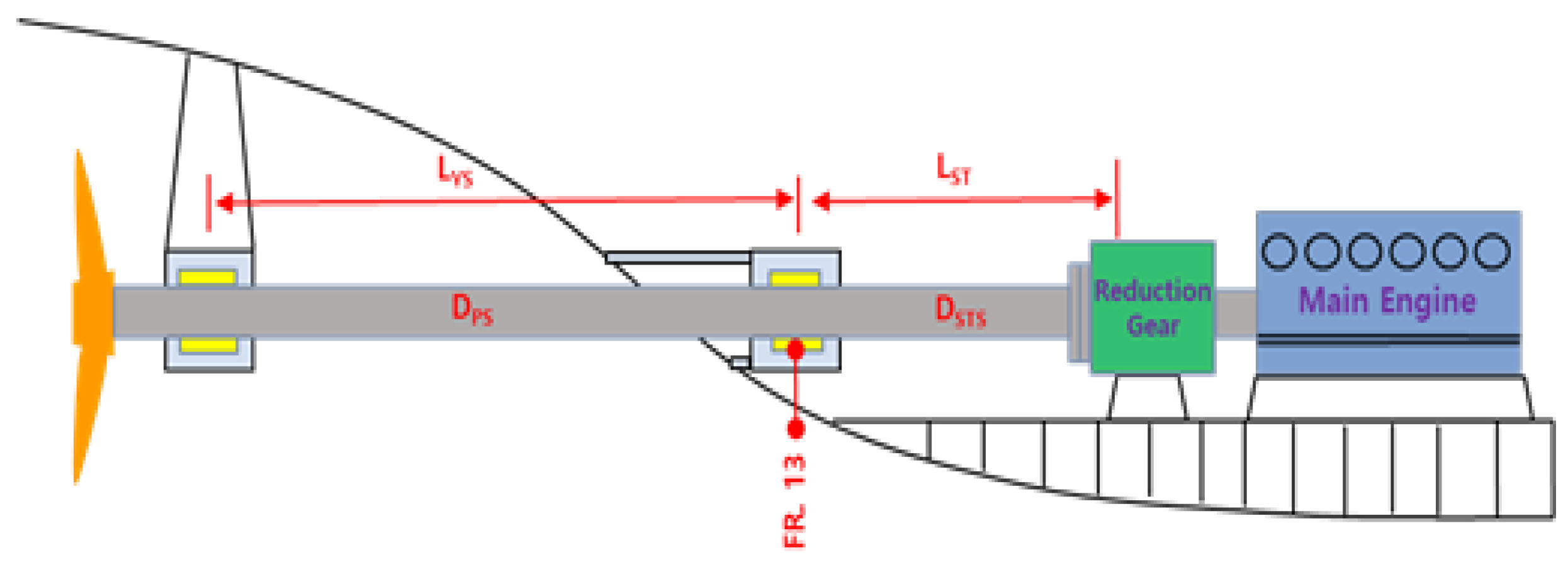
Figure 7.
Arrangement of the propulsion shafting system without stern tube bearing (Case II).
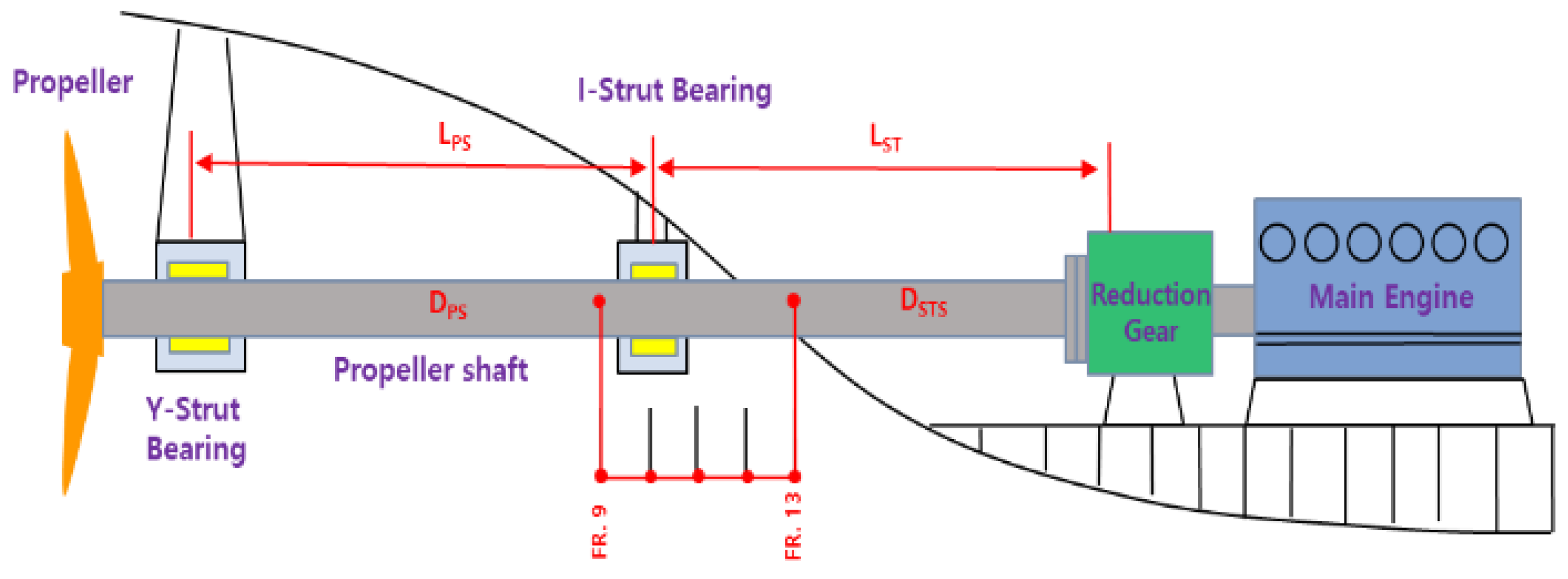
Figure 8.
Procedures for the optimum arrangement of the propulsion shafting system.
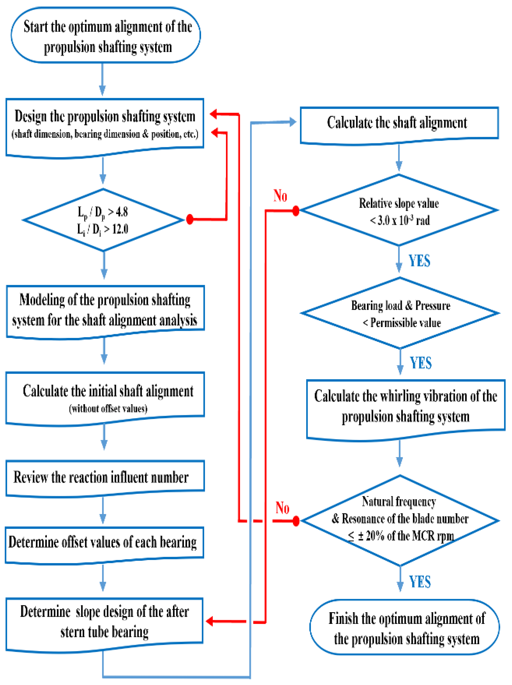
Figure 9.
Comparison results of bearing span per diameter of a sample ship according to varied bearing position.
Figure 9.
Comparison results of bearing span per diameter of a sample ship according to varied bearing position.
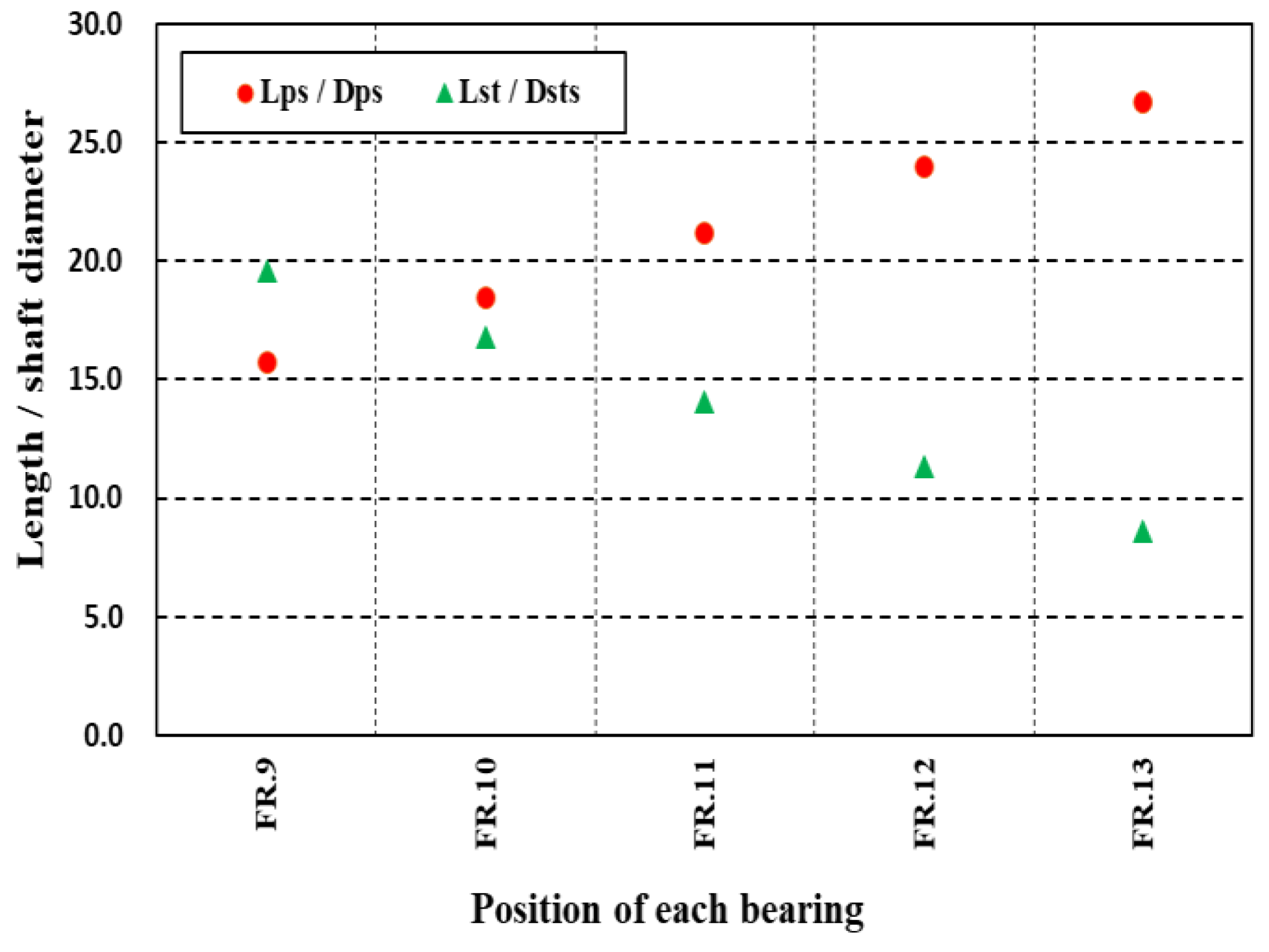
Figure 10.
Offset deviation between R/G bearings according to varied position of the I strut bearing.
Figure 10.
Offset deviation between R/G bearings according to varied position of the I strut bearing.
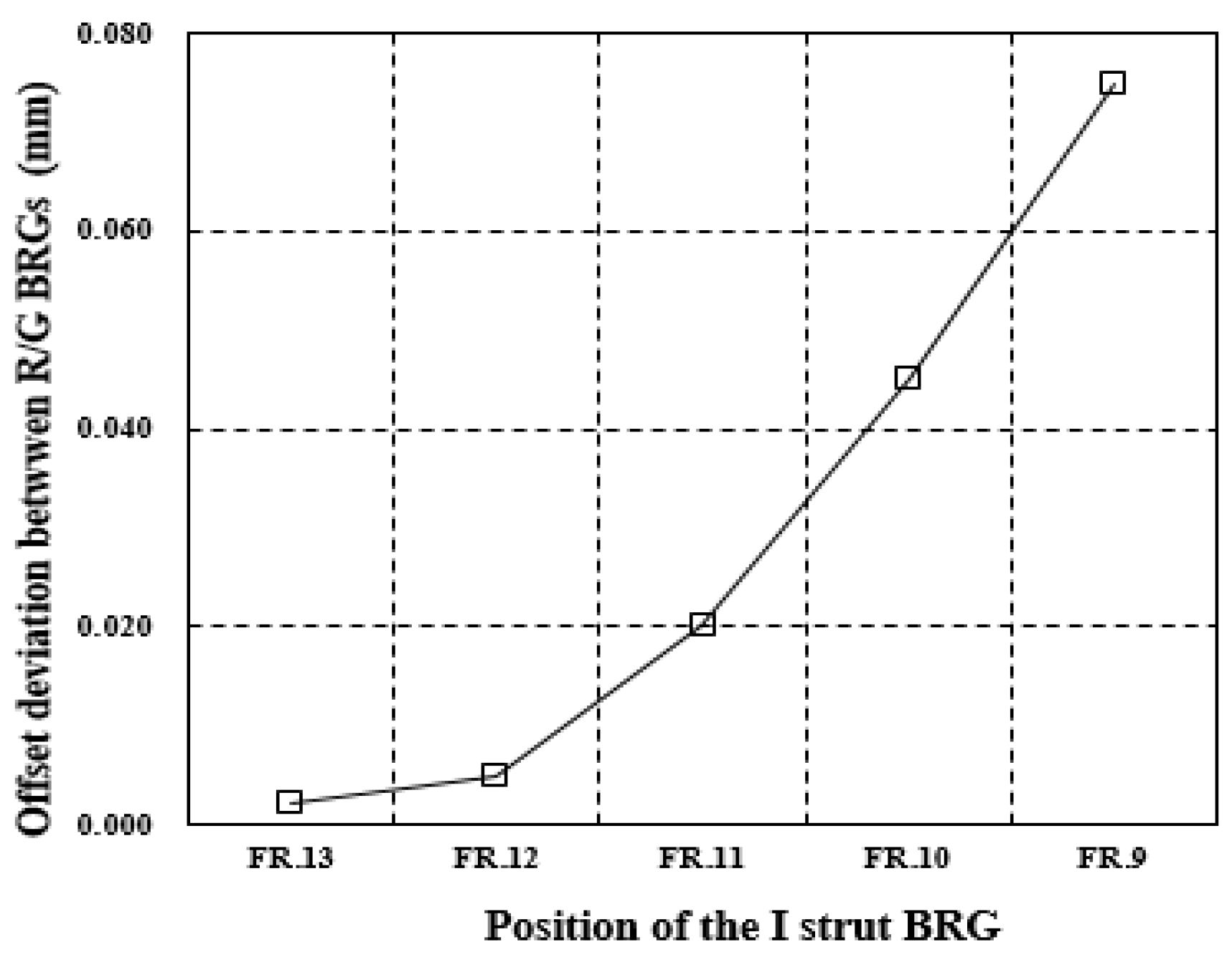
Figure 11.
Comparison results of bearing loads according to varied position of the I strut bearing: (a) Cold static condition; (b) Hot static condition; (c) Hot dynamic condition (-15% downward); (d) Hot dynamic condition (+30% upward).
Figure 11.
Comparison results of bearing loads according to varied position of the I strut bearing: (a) Cold static condition; (b) Hot static condition; (c) Hot dynamic condition (-15% downward); (d) Hot dynamic condition (+30% upward).
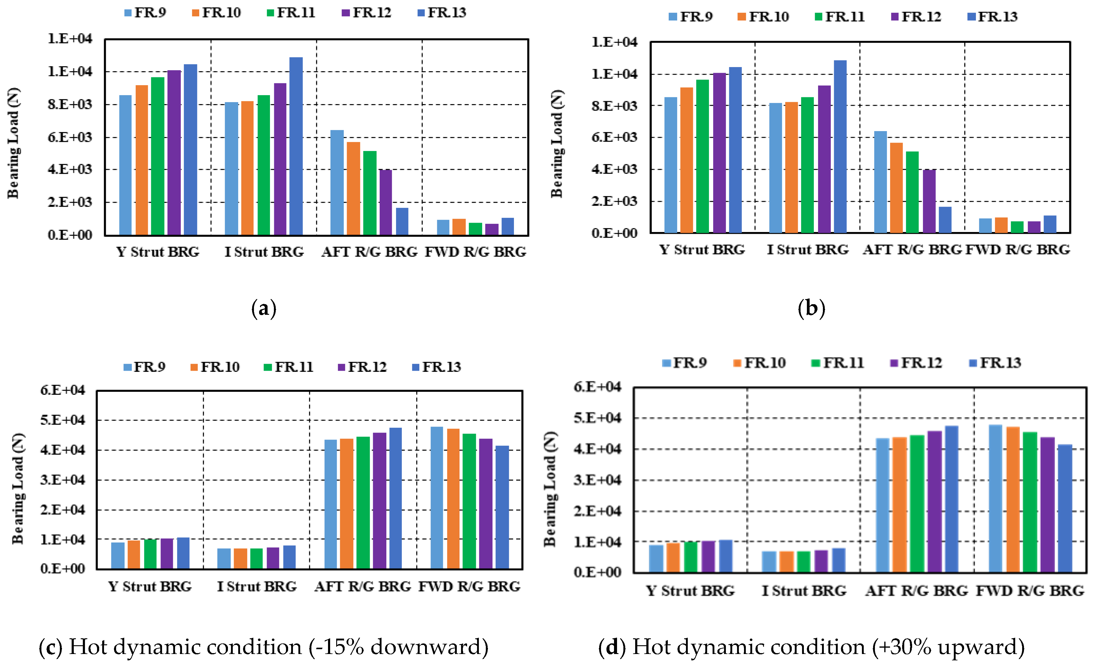
Figure 12.
Comparison results of the shaft bending moment according to varied position of the I strut bearing: (a) Cold static condition; (b) Hot static condition; (c) Hot dynamic condition (-15% downward); (d) Hot dynamic condition (+30% upward).
Figure 12.
Comparison results of the shaft bending moment according to varied position of the I strut bearing: (a) Cold static condition; (b) Hot static condition; (c) Hot dynamic condition (-15% downward); (d) Hot dynamic condition (+30% upward).
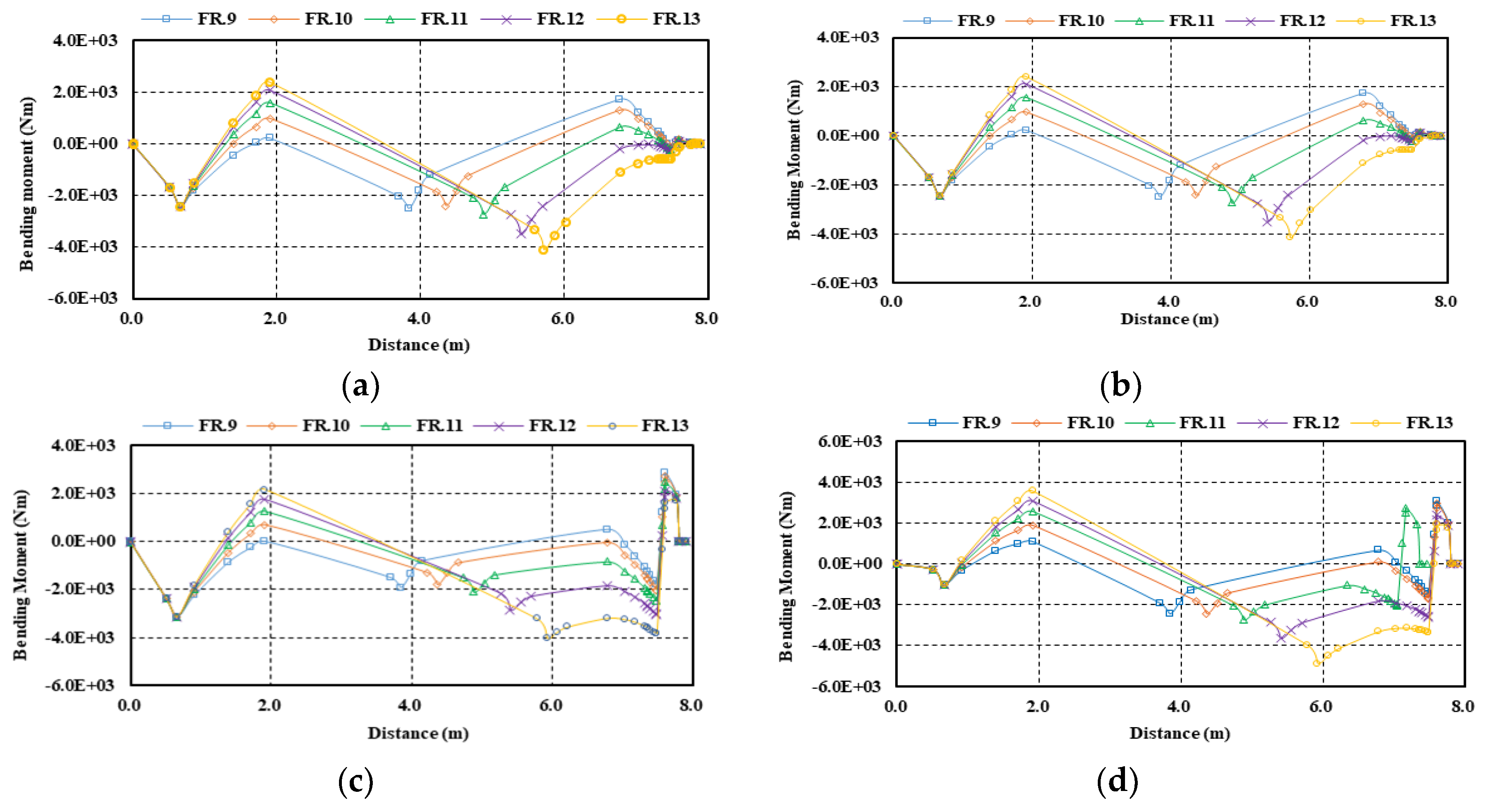
Figure 13.
Analysis results of the relative amplitude according to varied position of the I strut bearing (by FEM): (a) 1st mode; (b) 2nd mode; (c) 3rd mode; (d) 4th mode.
Figure 13.
Analysis results of the relative amplitude according to varied position of the I strut bearing (by FEM): (a) 1st mode; (b) 2nd mode; (c) 3rd mode; (d) 4th mode.
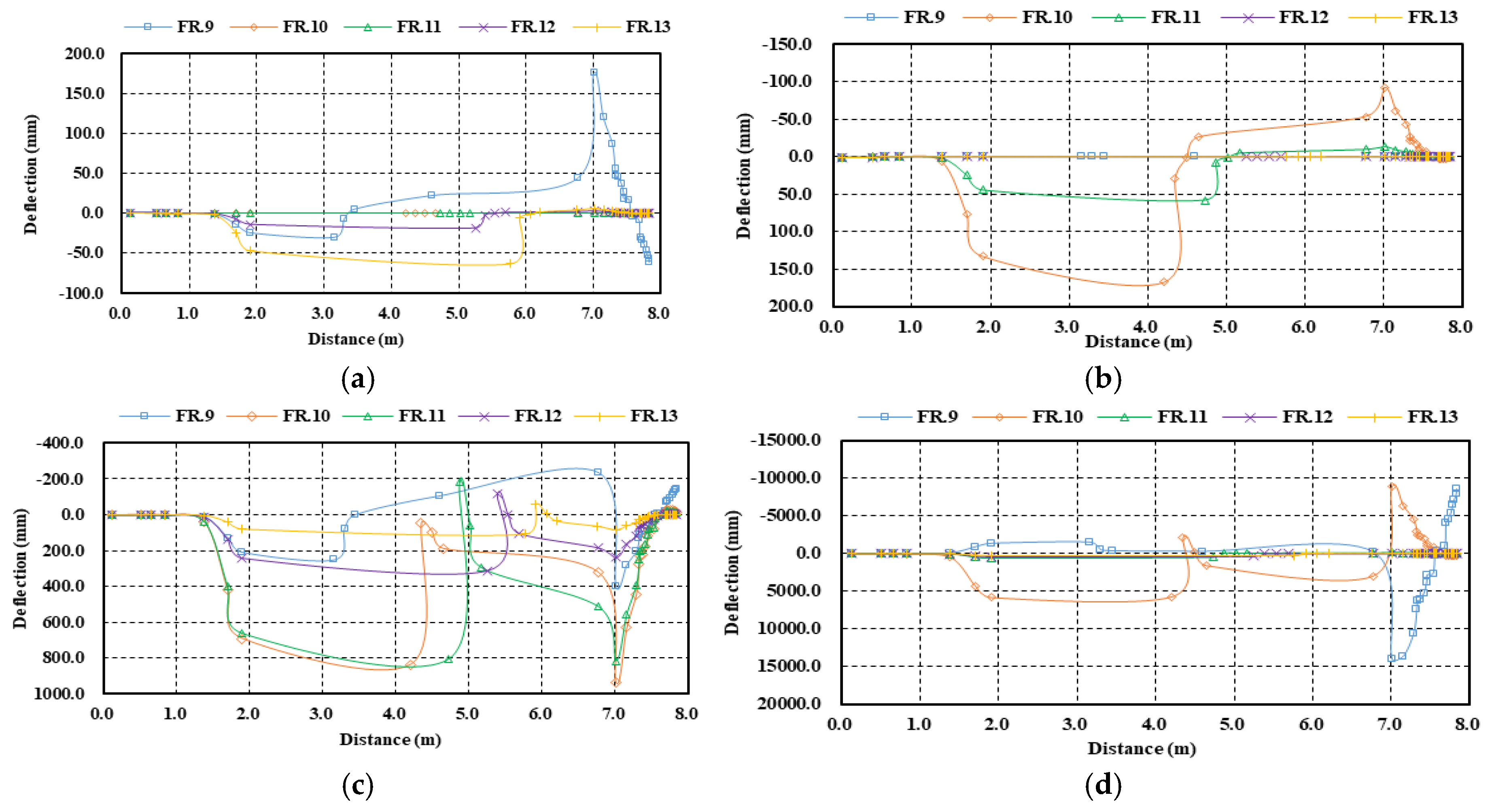

Table 1.
Specifications of the propulsion shafting system.
| Items | Detail |
|---|---|
| Vessel type | Special purpose ship |
| Propulsion Engine | |
| Type | 13,340 × 66.5 |
| MCR (kW) x rpm | 1,029 x 2,100 |
| Reduction gear | 3,256 |
| Model | WAF 563 |
| Gear ratio | 5.05 |
| Shaft | |
| Dia. of propeller shaft (mm) | 190 |
| Length of propeller shaft (mm) | 7,337 |
| Dia. of gear shaft (mm) | 140 |
| Length of gear shaft (mm) | 442.5 |
| Propeller | |
| Number of blade | 4 |
| Diameter (mm) | 1,650 |
| Weight (kg) | 429.7 |
Table 2.
Specifications of each bearing.
| Items | Detail |
|---|---|
| Y strut bearing | |
| Type | Thordon |
| Inner diameter (mm) | 195.0 |
| Effective length (mm) | 730.0 |
| Clearance (mm) | 1.34 |
| Max. permissible load (N) | 78,120 |
| Max. permissible pressure (N/mm2) | |
| I strut bearing | |
| Type | Thordon |
| Inner diameter (mm) | 190.0 |
| Effective length (mm) | 300.0 |
| Clearance (mm) | 1.32 |
| Max. permissible load (N) | 31,120 |
| Max. permissible pressure (N/mm2) | 0.55 |
| Stern tube bearing | |
| Type | Thordon |
| Inner diameter (mm) | 190.0 |
| Effective length (mm) | 150.0 |
| Clearance (mm) | 1.32 |
| Max. permissible load (N) | 15,560 |
| Max. permissible pressure (N/mm2) | 0.55 |
| Afterward reduction | |
| Type | Roller bearing |
Table 3.
Change of the design parameter in sample ship according to each case.
| Case | Stern tube bearing position | I strut bearing position |
|---|---|---|
| Case Ⅰ | Frame 13 | Frame 13 |
| Case Ⅱ | - | Frame 12 |
| Case Ⅲ | - | Frame 11 |
| Case Ⅳ | - | Frame 10 |
| Case Ⅴ | - | Frame 9 |
Table 4.
Reaction influence number (N/1.0mm) of each bearing when lowering the bearing offset of each bearing by 1.0mm.
Table 4.
Reaction influence number (N/1.0mm) of each bearing when lowering the bearing offset of each bearing by 1.0mm.
| Case | Y strut bearing |
Stern tube bearing |
I strut bearing |
Afterward reduction gear bearing |
Forward reduction gear bearing |
|---|---|---|---|---|---|
| Case Ⅰ (FR.13) | 223 | 21,320 | - | 489,050 | 324,435 |
| Case Ⅱ (FR.12) | 282 | - | 11,012 | 334,912 | 241,653 |
| Case Ⅲ (FR.11) | 364 | - | 7,106 | 253,755 | 192,962 |
| Case Ⅳ (FR.10) | 485 | - | 5,375 | 204,793 | 161,425 |
| Case Ⅴ (FR.9) | 674 | - | 4,627 | 172,452 | 139,530 |
Table 6.
Natural frequency of the free whirling vibration for a sample vessel (unit:rpm).
| Method | Case I | Case II | Case III | Case IV | Case V |
|---|---|---|---|---|---|
| Panagopulos formula | 1146.2 | 1285.8 | 1432.42 | 1587.0 | 1954.0 |
| Jasper-Rayleigh formula | |||||
| Still stand 1st order | 1336.9 | 1436.7 | 1546.8 | 1668.9 | 1972.7 |
| Forward whirling 1st order | 1432.1 | 1547.5 | 1674.7 | 1814.8 | 2157.2 |
| Backward whirling 1st order | 1258.1 | 1346.5 | 1444.1 | 1553.1 | 1828.4 |
| Finite Element Method | 1727.6 | 2089.8 | 2217.5 | 2217.7 | 1915.4 |
Table 7.
Natural frequency of the free whirling vibration for a sample vessel (1st propeller blade number) (unit:rpm).
Table 7.
Natural frequency of the free whirling vibration for a sample vessel (1st propeller blade number) (unit:rpm).
| Method | Case I | Case II | Case III | Case IV | Case V |
|---|---|---|---|---|---|
| Panagopulos formula | 286.5 | 321.6 | 358.1 | 396.8 | 488.51 |
| Jasper-Rayleigh formula | |||||
| Still stand 1st order | 334.2 | 359.2 | 386.7 | 417.2 | 493.2 |
| Forward whirling 1st order | 358.0 | 386.9 | 418.4 | 453.7 | 539.3 |
| Backward whirling 1st order | 314.5 | 336.6 | 361.0 | 388.3 | 457.1 |
| Finite Element Method | 431.9 | 522.5 | 554.4 | 554.4 | 478.9 |
Disclaimer/Publisher’s Note: The statements, opinions and data contained in all publications are solely those of the individual author(s) and contributor(s) and not of MDPI and/or the editor(s). MDPI and/or the editor(s) disclaim responsibility for any injury to people or property resulting from any ideas, methods, instructions or products referred to in the content. |
© 2025 by the authors. Licensee MDPI, Basel, Switzerland. This article is an open access article distributed under the terms and conditions of the Creative Commons Attribution (CC BY) license (http://creativecommons.org/licenses/by/4.0/).
Copyright: This open access article is published under a Creative Commons CC BY 4.0 license, which permit the free download, distribution, and reuse, provided that the author and preprint are cited in any reuse.


