
Submitted:
19 April 2024
Posted:
19 April 2024
You are already at the latest version
Abstract
This paper introduces a rigorous and comprehensive approach for the assessment of marine shafting systems through the utilization of an advanced Pi-Theorem based scaling methodology. Integrating journal bearing similarity assessment and shaft-line scaling methodology with advanced dimensional analysis, the study aims to provide a methodology foundation for systematic replication and analysis of marine shafting systems through scaled models. The proposed scaling methodology ensures geometric and mechanical similarity in terms of shaft-line deflection, considering key scaling parameters such as shaft length, diameter, weight, loads, rotational speed, material properties, bearing locations, and offsets. The advanced dimensional analysis computes specific non-dimensional ratios to guarantee a close resemblance between a real-size system and a scaled lab model, enabling meaningful experimentation. The methodology is analytically derived and validated with numerical simulations for a case study, conducting comparative analysis, evaluating discrepancies, and utilizing the integrated framework for experimentation.
Keywords:
Pi-Theorem
; dimensional analysis
; marine shafting systems
; journal bearing performance
; comparative analysis
; similarity assessment
1. Introduction and Literature Trends
In marine engineering, understanding the complex static and dynamic phenomena in marine propulsion shafts is essential for ensuring the reliability and longevity of these critical components. However, the translation of experimental results from small-scale physical models to full-scale marine propulsion systems presents unique challenges. FIrst, a literature review is performed to explore the application of dimensional analysis and the Buckingham π-theorem [1,2] in achieving dynamic similarity between physical models and full-scale marine propulsion shafts, extracting valuable research insights for real-world applications.
The study conducted by Korczewski and Marszałkowski [3] introduces a crucial aspect of diagnosing the fatigue of marine propulsion shafts by analyzing the energy aspects of fatigue. They proposed to adopt the high-cycle fatigue syndrome consisting of diagnostic symptoms determined from the function of the propulsion shaft action related to the transformation of mechanical energy into work and heat, and the generation of mechanical vibrations and elastic waves of acoustic emission [4]. The authors emphasize that even the most sophisticated physical models developed in laboratory settings lack practical utility in diagnostics unless the research results can be properly transferred to the real-world scale. In response to this challenge, they propose a methodology that employs dimensional analysis and the Buckingham π-theorem to identify dimensionless numbers representing dynamic similarity between physical models and full-scale marine propulsion shafts. These dimensionless numbers serve as a bridge, enabling the translation of research findings concerning energy processes associated with fatigue from physical models to actual marine propulsion systems. The preceding sections of the article by Korczewski and Marszałkowski [4,5] provide critical context for the importance of their research. They present the outcomes of both model and experimental studies focusing on the fatigue processes of propulsion shafts. Active experiments are conducted on a specially designed physical model of a rotary propulsion system, faithfully replicating the operation of full-size counterparts. The research demonstrates a direct relationship between changes in the deflection of the rotary propulsion line and the dissipation of kinetic energy from rotating masses, along with the accumulation of internal energy within construction materials. This connection is crucial, as it marks the onset of fatigue damage characterized by energy-related processes, including vibroacoustic and thermal phenomena. These processes manifest as observable diagnostic symptoms, indicating changes in the fatigue state of the structural materials comprising the propulsion shaft. To assess the diagnostic capabilities of the defined fatigue condition characteristics, the authors conduct a program of experimental tests. This program scrutinizes two statistical hypotheses: the significance of factors influencing the fatigue process [4] and the adequacy of a regression equation describing the fatigue life of propulsion shafts in terms of energy [5]. Notably, these experiments are conducted on physical models, reflecting the operation of real full-size systems. However, a key limitation arises from the transition to a smaller scale, which may inadvertently omit certain phenomena and processes [6].
To overcome this limitation, dimensional analysis emerges as a powerful tool. It is widely recognized in engineering literature and has been successfully applied in various fields, including vehicle dynamics [7,8,9]. Dimensional analysis serves as a means to determine the form of functions describing processes when only the relevant parameters are known. The fundamental premise is that the dimensions of these functions (physical quantities) must align with the dimensions of the power product created from the parameters that significantly influence the fatigue process.
The authors of the present paper have addressed, in the past, several problems related to the performance assessment and design optimization of traditional marine shafting systems. More particularly several concerns have been addressed especially regarding the design of the stern-tube area and the need for a single or double sloped aft stern tube bearing [10]. Furthermore, the assessment of existing designs has been analyzed in [11], raising some concerns regarding the underlying design optimization functions. In that particular case study of the shafting system of an 82000 DWT bulk carrier, the initial alignment of the vessel was compared against the performance corresponding to different bearing offset combinations. Similar studies have been recently reported by other researchers especially focusing in the important effect of hull structural deformations in regard to shaft alignment [12,13,14].
Despite the robust application of dimensional analysis in various engineering domains, currently trending in the field of dimensional analysis in data modeling [15], there remains a noticeable dearth of literature addressing the similarity of marine propulsion systems and fault diagnosis of rotor-bearing system based on experimental tests conducted on a small scale [16,17]. This gap underscores the need for further research in this area, as marine propulsion systems play a critical role in the operation of vessels and are subject to unique challenges.
2. Small Scale Model Development - Scope
Marine propulsion systems play an important role in the efficiency and performance of vessels. Achieving a comprehensive understanding of these systems is crucial for optimizing their design and operation. In this section the concept of similarity in marine propulsion systems is introduced, highlighting its significance and relevance in the field of marine engineering. Similarity in marine propulsion systems refers to the ability to replicate key characteristics or behaviors of full-scale systems in scaled-down laboratory models. This concept is fundamental for several reasons:
- →
- Model Testing: Conducting experiments on full-scale marine propulsion systems is often impractical and cost-prohibitive. Scaled-down models provide a cost-effective alternative. Similarity ensures that the behaviors observed in model tests accurately represent those of the full-scale systems.
- →
- Performance Prediction: Engineers use similarity to predict the performance of full-scale marine propulsion systems based on model test results. By maintaining similarity in key parameters, such as flow rates and proper dimensionless numbers (e.g. the Reynolds number), they can extrapolate data obtained from model tests to real-world scenarios.
- →
- Prototype Development: Similarity aids in the development and validation of prototype systems. By conducting tests on scaled-down prototypes, engineers can refine designs and identify potential issues before constructing full-scale systems.
- →
- Research and Development: Research endeavors in marine engineering often require experimentation to explore new technologies and assess their impact on propulsion systems. Similarity ensures that the findings from model tests are relevant to real-world applications.
Three levels of similarity are distinguished and assumed in different engineering applications, namely;
- Geometric similarity: the ratio of all corresponding lengths in model and prototype are the same (i.e. they have the same shape),
- Kinematic similarity: the ratio of all corresponding lengths and times (and hence the ratios of all corresponding velocities) in model and prototype are the same,
- Dynamic similarity: the ratio of all forces in model and prototype are the same e.g. Re = (inertial force) / (viscous force), is the same in both.
Geometric similarity is almost always assumed and especially in practical applications where a smaller prototype is studied in a laboratory environment instead of the real size model. To achieve similarity in marine propulsion systems and especially journal bearings, several critical parameters must be considered, according to literature [5,7,8,9], including:
- ➢
- Reynolds Number: This dimensionless number characterizes the flow regime within the system. Maintaining a consistent Reynolds number between the model and full-scale system ensures similarity in flow behavior.
- ➢
- Froude Number: The Froude number relates to the dynamic similarity of the system, particularly used in terms of wave resistance and free surface effects. Matching Froude numbers is essential for replicating these phenomena accurately.
- ➢
- Geometric Scaling: Properly scaling the geometry of the model in relation to the full-scale system is crucial. This includes considerations of length, width, and height ratios.
- ➢
- Flow Rates and Velocities: Ensuring that flow rates and velocities within the model match those of the full-scale system is vital for achieving similarity in propulsion characteristics.
- ➢
- Material Properties: Materials used in the model, such as of the hull and propellers, should mimic the properties of their full-scale counterparts to accurately replicate performance.
In conclusion, similarity is a fundamental concept in marine engineering, enabling engineers and researchers to conduct meaningful experiments, predict performance, and develop efficient propulsion systems. By carefully matching key parameters and maintaining dimensional and dynamic similarity, marine engineers can leverage scaled-down models to gain insights that are applicable to the complex world of full-scale marine propulsion systems.
Creating a system scaling methodology to construct a small-scale shafting system closely mirroring the dimensions and characteristics of an actual large-scale asset, would respond to the prevailing trends in marine engineering, which underscore a growing concern regarding shafting system failures [18,19]. These failures are frequently attributed to factors such as the ship's hull stiffness and the overall system rigidity, which can lead to excessive loading, particularly in the stern tube area.
At the same time, experimental evaluations and assessments conducted firstly at a reduced scale model often incur substantially smaller cost, compared to the direct development of a large-scale test-rig. Furthermore, such scaled-down tests can often be highly customizable to fit different large-scale applications, rendering them even more cost-effective. Consequently, there is a preference for piloting at custom-made small-scale test rigs before testing in large-scale rigs.
Moreover, there exists a notable absence of a comprehensive methodology to establish a direct correlation between the model and the actual parameters of the system. Scaling the system solely based on length units does not provide a proper solution, as other intricacies tied to material properties, boundary conditions and forces/loads significantly influence system behavior. Consequently, the absence of a standard methodology to facilitate this conversion into a scaled-down test rig has been a challenge.
Hence, one of the primary priorities is the development of a rigorous and robust scaling methodology. This methodology is designed to support the scaling process both analytically and numerically, ensuring a comprehensive and accurate transition from large-scale assets to small-scale test rigs.
3. Theoretical Background for Dimensional Analysis of Marine Shafting Systems
Many complex engineering-related problems defy straightforward mathematical solutions. In such instances, an analytical approach based on the dimensions of the involved quantities becomes invaluable. This approach, known as dimensional analysis, has a wide range of applications and benefits within the, engineering domain [7,8,9]. Here, the key uses and advantages of dimensional analysis are highlighted:
- →
- Reducing Variables: Dimensional analysis serves as a powerful tool for reducing the multitude of variables within a problem. By distilling the essential dimensions, engineers can focus their efforts on studying or plotting a more manageable set of variables.
- →
- Experiment Planning: It plays a crucial role in experiment planning. Engineers can employ dimensional analysis to design experiments effectively, ensuring that the selected variables align with the problem's key dimensions.
- →
- Engineering Model Design: Engineers often create models to simulate real-world phenomena. Dimensional analysis aids in the design of these engineering models, helping researchers interpret model data accurately.
- →
- Parameter Prioritization: Dimensional analysis provides a means to emphasize the relative importance of parameters within a problem. This prioritization is crucial in understanding the dominant factors affecting a system.
- →
- Unit Conversion: A relatively common but essential application of dimensional analysis is unit conversion. It facilitates the seamless transition of measurement units from one system to another, ensuring consistency and clarity in engineering calculations.
In essence, dimensional analysis encompasses any mathematical operation that incorporates units or dimensions. This versatile technique empowers engineers to tackle intricate problems, streamline their investigations, and achieve a deeper understanding of complex engineering systems. Dimensions of commonly derived mechanical quantities for dimensional analysis are given in Table 1.
3.1. Dimensional Analysis: Lubrication of Bearings
Journal bearings, where a shaft rotates within a bearing, are fundamental components in many mechanical systems. The behavior of such bearings can be understood and analyzed through the application of dimensional analysis, shedding light on the equilibrium between fluid viscous resistance and pressure differences within the system.
Equilibrium Factors:
- Viscous Resistance: Viscous resistance occurs at the surfaces of both the rotating shaft and the bearing and is commonly quantified as friction force or friction coefficient. This resistance is a key factor in understanding the quantities related to the dynamics of the bearing (see Table 1).
- Pressure Difference: The pressure difference arises from the transfer of force, typically carried by the shaft, which is then distributed as pressure within the lubricating fluid. This distribution plays a significant role in the functioning of the bearing.
In the context of dimensional analysis [7,8], a direct formulation is often employed. This entails describing an effect parameter, such as bias (ratio of bias distance to bearing diameter), friction drag (F), or fluid flux (Q), as a function of various cause parameters. These cause parameters encompass both geometric factors (Rbearing, Rshaft) and physical properties (viscosity coefficient μ of the lubricating fluid, environmental pressure p0 - particularly relevant in sealing bearings, load W, and relative velocity v or angular velocity ω). Conversely, inverse formulation considers bias (or other effect parameters), load W, sliding velocity v, fluid viscosity μ, and environmental pressure p0 as given values. In this scenario, the geometric characteristics of the shaft and bearing must be determined.
In many cases, the inertia effects are negligible. The ratio of inertia force to viscous force, expressed as:
, tends to be small, often on the order of < 0.001.
However, in situations where the relative sliding velocity v or mean space h is significantly large, to the extent that the magnitude of this factor approaches 0.1 and inertia effects must be taken into account [7].
In the case of journal bearings, there are seven key parameters that should be considered, namely; R-radius, h-film thickness, μ-lubricant viscosity, p0-pressure, W-load, v-rotational speed and a-bias (or friction drag or fluid flux). These seven parameters (R, h, μ, p0, W, v, a) are interrelated variables within the system, and their behavior can be described by an implicit function:
f (R, h, μ, p0, W, v, a) = 0
This equation encapsulates the relationships between these parameters, providing a foundation for the analysis and understanding of journal bearing lubrication.
Taking R, p0, and v as a unit produces 7-3=4 independent variables:
Where: μω/p0 represents ratio of viscous stress to environmental pressure, the second and third are dimensionless geometrical ratios and the fourth represents the loading-to-environmental pressure ratio.
Assuming a Rprototype / Rmodel = n, reduction ratio yields:
If (𝜇𝑣)𝑚= (𝜇𝑣)𝑝, for a similarity of (𝜇𝑣/(𝑝0 𝑅)), yields => (𝑝0∙𝑅)𝑚= (𝑝0∙𝑅)𝑝 , therefore:
Summarizing, a generalized journal bearing similarity can be formulated as:
3.2. Dimensional Analysis: Deflection of Beams and Shafts
In a similar way, understanding the behavior of shafts (or beams) is paramount. These components play a vital role in transmitting power, supporting loads, and maintaining structural integrity in various applications. To gain insights, from a scaled model, into the intricate mechanics of shafts, engineers often turn to the concept of similarity. It involves examining how various factors, such as geometry, material properties, loads, and operating conditions, interact and influence the performance of shafts. Through similarity analysis, engineers can draw parallels between different shaft designs, allowing for a deeper comprehension of their mechanical responses.
In this exploration of similarity in shafts (or equivalent beam elements), the fundamental principles of dimensional analysis will be addressed, seeking to identify the key parameters and relationships that govern the behavior of these essential mechanical components.
Geometric similarity is not necessary for modeling some simple problems in solid mechanics, such as a problem related to simply-supported elastic beam Figure 1. For distributed loading q(x) applied on the beam of unit length, deflection of the simply-supported beam w = w(x) satisfies the following equation and boundary conditions:
In Eq.(2.1), L = beam length, E = Young’s modulus, and I = cross-section moment and EI= flexural rigidity of the beam with dimension FL2 (F = dimension of force). Distributed loading q(x) can be expressed by characteristic parameters such as characteristic loading qm and characteristic length Lq besides independent variable x. Deflection of the beam is a function of parameters introduced in Eq. (2.1):
w = f (x, L, EI, qm Lq)
This problem has two independent dimensions. Taking l and EI as a unit system (5-3=2 independent dimensions) produces:
If the second and third terms are constants in the model and prototype, i.e.:
then dimensionless distribution of deflection is the same for model and prototype:
Modeling experiments does not require the geometry of the model to be similar to that of the prototype but does require the cross-section moment I to satisfy Eq. (2.4). If material of the beam in the model is the same as material in the prototype, a square-shaped cross-section can simulate the I-shaped cross-section and a solid cross-section can be used to simulate a hollow one.
Unfortunately, the shafting system geometry for “traditional designs” of “large” merchant marine ships is quite more complex than a simply-supported elastic beam, especially in the propeller shaft region, where the cantilever beam deflection would be a more accurate representation.
Similarly, the pi-Theorem can be utilized to enable similarity in a cantilever beam such as:
Figure 2.
Deflection of a cantilever beam.
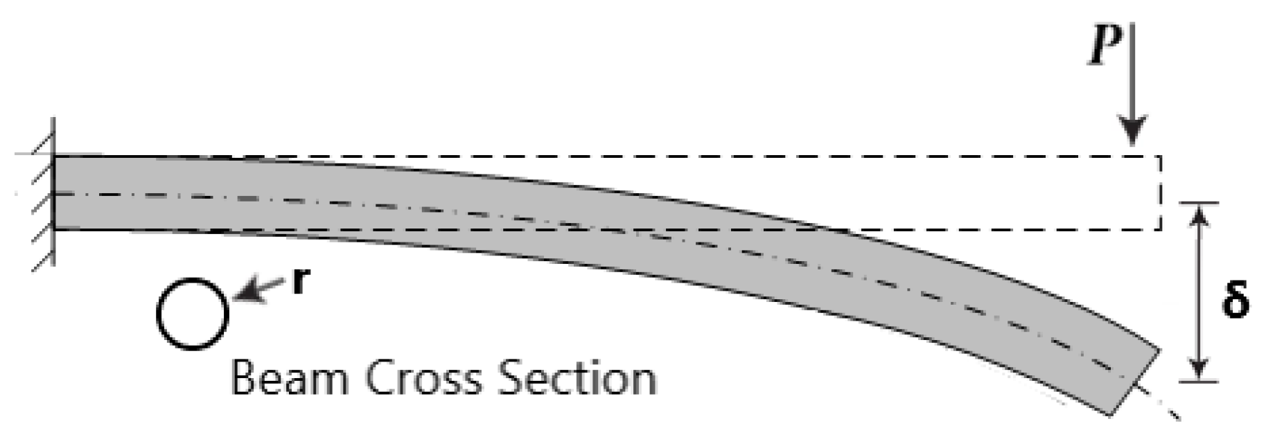
Step 1: In the study of the deflection of a cantilever beam, the parameters involved are the applied force (P), deflection (δ), modulus of elasticity (E), beam radius (r), and the beam length (l). A total of 5 parameters (n=5) is involved in this problem.
Step 2: The basic dimensions involved are summarized in the following table:
Hence, 2 basic dimensions (k=2) are involved in this problem.
Where: qm = πD2/4 * ρ and I = πD4 / 64
Step 3: According to the Buckingham pi theorem, the number of pi terms is 3 (n-k=5-2=3).
Step 4: The next task is to find the form of the pi terms. Select the modulus of elasticity (E) and beam radius (R) as the repeating parameters. The pi terms are then given by:
Π1 = PEa1rb1
Π2 = δEa2rb2
Π3 = ΙEa3rb3
The exponents of the first pi terms are determined as follows:
Π1 = PEa1rb1 = (F)(FL-2)a1(L)b1 = F(1+a1)L(-2a1+b1)
In order for Π1 to be dimensionless:
F: 1+a1=0 => a1=-1
L: -2a1+b1=0 => b1=-2
Hence: Π1 = P/Er2 Eq. (3.3)
Similarly, Π2 = δ/r Eq. (3.4) and Π3 = Ι/r Eq. (3.5)
According to beam bending theory, the deflection of a circular beam is given by:
, thus, Π2 in Eq. (3.4) can be rewritten as: Eq. (4)
Which is in agreement with the results obtained from dimensional analysis found also in literature for cantilever beam, but similarity cannot be ensured at a mixed type of beam including both a cantilever and a simply supported beam, since the similarity parameters in {Eq. (2.3-2.5)} are not the same as the ones demanded in {Eq. (3.3-3.5)}. Therefore, an additional step is required, to couple this theoretical background with the complexity of the application at hand. This important step is presented in Section 4.1: “Advanced Dimensional Analysis for a Scaled Shafting System Model”.
4. Method Assessment with Numerical Simulations
4.1. Advanced Dimensional Analysis for a Scaled Shafting System Model
In this section, an in-depth exploration of the critical parameters integral to the assessment of similarity within the marine shafting system is addressed. These parameters encompass a wide array of factors that dictate the system's behavior, ensuring its accurate representation in scaled models.
Geometric Data Parameters:
- Shaft Length (L): The longitudinal extent of the shafting system is a fundamental parameter influencing its mechanical properties.
- Shaft Diameter (D): The cross-sectional dimensions of the shaft are equally pivotal, impacting its structural integrity and load-bearing capacity.
Load-Related Parameters:
- Shaft Weight (W): The gravitational force exerted on the shaft due to its mass is a paramount consideration for load simulation.
- External Loads: These encompass any additional forces or moments applied to the shafting system during operation.
- Shaft Rotational Speed (ω): The rate at which the shaft rotates plays a significant role in its dynamic response and performance characteristics.
Material Properties Parameters:
- Modulus of Elasticity (E): The material's stiffness, quantified by the modulus of elasticity, is indispensable for assessing the system's deformation under load.
- Shaft Inertia (I): The rotational inertia of the shaft is instrumental in comprehending its resistance to changes in angular velocity.
Support Configuration Parameters:
- Bearing Locations: The positioning of bearings along the shafting system has a profound impact on its static and dynamic behavior.
- Vertical Offset: The vertical offset applied to the system during shaft alignment is a crucial factor.
Figure 3.
Key Scaling Parameters for Traditional Marine Shafting Systems.
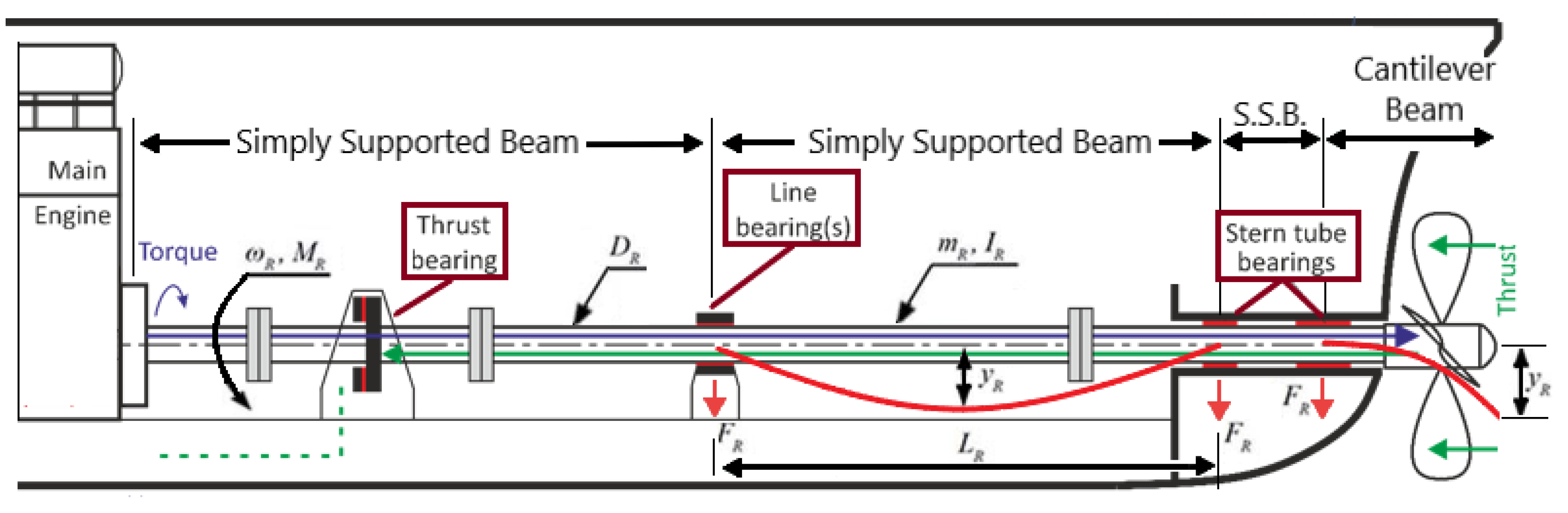
The marine shafting system assumes a complex structural configuration. It comprises a combination of simply supported beams at specific regions, notably the intermediate shaft and the crankshaft. Conversely, the aft end, housing the propeller shaft, assumes the form of a cantilever beam. This structural diversity necessitates careful assessment of similarity parameters to accurately replicate the system's scaled model.
The first step to implement and validate the scaling methodology includes the development of the Real Model of this system in full scale. Then scaling of the system may be implemented ensuring that the requirements set by Equations {Eq. (2.3-2.5)} hold true, namely;
Then the parameters of the scaled model may be calculated following the Model Parameter Ratios listed in Table 4.
Figure 4.
Real, Scaled and Equivalent Shaft Models.

This would create the Scale Model (M), which looks quite similar, from a geometric perspective, to the original Real Model. Then the respective shaft alignment simulations in Real and Scale Model can be calculated and the shaft deflection (UY) in the Real Model is also estimated in a reverse calculation (UYR=UYM*n 2 / 3) using the Scale Model shaft displacement data. These shaft deflection values demonstrate a significant discrepancy attributed especially in the aft shaft area that can be visually illustrated, using the results from an example case, presented in the Figure 5.
The reason for this discrepancy in data is attributed to the complexity of the system and the fact that Eq. (2.3-2.5), for simply supported beam elements, should hold true at the same time as the Eq. (3.3-3.5), for cantilever beams. A novel way to work around this problem is actually inherent within the parameters related to Eq. (2.3-2.5,3.3-3.5) and requires a different modeling approach. More particularly the present approach requires modeling at a fixed Modulus of Elasticity (E), with a predetermined fixed shaft diameter (D) scaling ratio (n) so: Dm=Dr/n, but the length of each beam is calculated on such a way to ensure that according to Eq. (5) the ratio qmL3 / EI = constant. Then, vertical displacements and Forces are calculated according to the respective Model Parameter Ratios. This new type of model is the Equivalent scaled Model (Model), which is essentially affecting the length to diameter ratio of beams in the propeller shaft differently, in comparison to the ones in the intermediate shaft and crankshaft.
Furthermore, a sensitivity analysis is performed to demonstrate that the Average Error remains very small irrespective of any numerical errors and the shaft diameter ratio (n) in particular. The results of these simulations are included in Figure 5 and Table 5, where the reverse calculation of the large scale (Real) shaft displacement is estimated utilizing data from a model that is n=69 on n=27.6 times smaller respectively.
4.2. Advanced Dimensional Analysis for Journal Bearing Model
Journal bearings are essential components in mechanical systems, playing a critical role in ensuring smooth and reliable operations. Evaluating the performance of these bearings is important to guarantee mechanical system efficiency and longevity. Traditionally, the Sommerfeld number has been employed as a metric to assess the performance similarity of different journal bearings. However, this approach has its limitations, prompting the exploration of more advanced techniques.
Derived utilizing Petrov's Law, where:
- 𝑁𝑠 is the rotor angular velocity (RPS)
- W is the applied load (N)
- η is the lubricant viscosity (Pa⋅ s)
- D is the bearing diameter (m)
- L is the bearing length (m)
- R is the bearing radius (m)
- c is the bearing radial clearance (m)
The most notable advantages of the Sommerfeld Number are:
- Ease of Use: The Sommerfeld number is a straightforward non-dimensional parameter.
- Comprehensive Assessment: It encompasses both design and operational aspects.
- Performance Characterization: It effectively characterizes the bearing's performance.
- Comparative Analysis: It facilitates comparisons between bearings under different operational conditions or with different designs.
However, the Sommerfeld number method, although a long-standing and widely utilized approach, has several important limitations, especially in non-traditional designs and operating conditions:
- Simplified Bearing Geometries: The Sommerfeld number approach relies on simplified bearing geometries, which may not accurately represent the complexities of real-world bearings.
- Misalignment Influence: Investigations into journal bearings have revealed that misalignment, especially under heavy loads and significant misalignment angles, substantially affects both the static and dynamic characteristics of the bearings. Existing methods often fall short in assessing such scenarios.
- Elastic Deformation Influence: It doesn't account for any elastic deformation effects.
- Surface Detail Omission: Surface roughness or texturing data is not included.
- Uniform Load Assumption: It assumes a uniform distribution of radial load W.
- Static Operating Condition: It is most applicable for precise "static" operating conditions.
- Inadequate Consideration of Operating Conditions: Traditional approaches struggle to account for various operating conditions and environmental factors that significantly impact bearing performance.
- Lubricant Assumption: It assumes that the clearance is always filled with lubricant, without considering oil starvation scenarios.
Dimensional analysis plays a pivotal role in understanding and addressing the challenges associated with journal bearing performance assessment. The primary objective of dimensional analysis in this context is to explore the characteristics of different bearing parameters under varying operating conditions. Furthermore, allows for a reduction in the number of independent variables involved in the assessment, simplifying the solution process and generalizing the results. In the pursuit of advanced dimensional analysis for journal bearing model evaluation, the present authors have also introduced AI techniques to overcome the limitations of traditional approaches. By considering misalignment and other real-world complexities, these techniques offer a more comprehensive assessment of performance similarity, ultimately contributing to the reliability and efficiency of mechanical systems [20].
To ensure bearing similarity the Sommerfeld Number was eventually utilized, ensuring that the bearings will operate, in the model scale, at a Sommerfeld Number similar to the prototype. An example of bearing scaling is illustrated in Table 6. In this example a set of ASTB and FSTB from a conventional Bulk Carrier were selected and all the geometric constraints of the small-scale bearings (scale ratio: n=18) were fixed. Additionally, the following constraints were considered for the small-scale bearings, namely: DShaft Nominal = 25 mm, μ = 0.07 Pa s, and the shaft (motor) will rotate at 1440 RPM, thus the load P becomes the key parameter that will ensure Sommerfeld Number similarity.
4.3. Coupled Dimensional Analysis Towards a Similar Small-Scale Model
This section addresses the integration of the two fundamental methodologies already discussed: (a) the Journal Bearing Similarity and (b) the Scaling Methodology using Advanced Dimensional Analysis in Marine Shafting Systems. This integration aims to create a unified framework for accurately replicating and analyzing marine shafting systems in scaled models.
The Scaling Methodology, as described in earlier sections, is primarily concerned with achieving geometric and mechanical similarity between a real marine shafting system and its scaled-down model. This methodology involves the identification of key parameters, such as shaft length, diameter, weight, external loads, rotational speed, material properties, bearing locations, and vertical offsets. By ensuring that specific scaling ratios and equations are met, the scaled model closely resembles the real system, thus allowing for meaningful experimentation and data extraction.
On the other hand, Advanced Dimensional Analysis, as discussed in previous sections, serves as a powerful tool for understanding the behavior of marine shafting systems under various operating conditions. It involves the computation of dimensionless parameters that capture the influence of different factors on system performance. This analysis leads to the reduction of independent variables, simplification of solutions, and generalization of results.
To merge these two methodologies effectively, a step-by-step approach is proposed:
- Establish Real Model (R): Begin by developing a full-scale real model of the marine shafting system, following the Scaling Methodology. This real model serves as the reference for the scaled-down model.
- Determine Scaling Parameters: Apply the Scaling Methodology to determine the appropriate scaling parameters and ratios.
- Dimensional Analysis: Apply Advanced Dimensional Analysis Methodology to compute the dimensionless parameters that capture the system's behavior under various operating conditions. These include geometric dimensions, material properties, loadings, and rotational speeds. This step allows for a deeper understanding of how different factors affect performance. Ensure that Eq.(2.3-2.5,3.3-3.5) are satisfied to achieve similarity between the real and scaled models.
- Create Equivalent Scaled Model (M): Using the scaling parameters obtained in the previous step, construct a scaled-down model that closely mimics the real model. This model is designed to adhere to the geometric and mechanical constraints dictated by the Scaling Methodology.
- Comparative Analysis: Conduct a comparative analysis (using Shaft Alignment simulations) between the real and scaled models. Examine the performance of the scaled model under various conditions and compare it to the real system. This step ensures that the scaled model accurately represents the behavior of the full-scale system.
- Error Assessment: Evaluate any discrepancies between the real and scaled models and assess the accuracy of the Equivalent Scaled Model.
- Validation and Experimentation: Utilize the integrated framework for experimentation and validation. Perform laboratory tests and data collection using the scaled model to gain insights into the behavior of the full-scale marine shafting system.
The integration of the Scaling Methodology and Advanced Dimensional Analysis provides a robust and comprehensive approach to replicate, analyze, and assess marine shafting systems in scaled models. By merging these methodologies, researchers and marine engineers can bridge the gap between theory and practical experimentation, ultimately enhancing the reliability and efficiency of mechanical systems in marine applications. This integrated framework empowers the exploration of complex real-world scenarios and fosters innovation in the field of marine engineering.
5. Application Case Study—“Bulk Carrier S”
5.1. Model Development for Small Scale Experimental Test-Rig
This section presents an integrated approach that combines two key methodologies: Journal Bearing Similarity and Scaling Methodology with Advanced Dimensional Analysis in Marine Shafting Systems. The goal is to perform a characteristic Case Study to assess the unified framework for replicating and analyzing marine shafting systems using scaled models.
The Scaling Methodology focuses on achieving geometric and mechanical similarity between real marine shafting systems and scaled-down models. This involves identifying key parameters like shaft length, diameter, weight, loads, rotational speed, material properties, bearing locations, and offsets. Specific scaling ratios ensure that the scaled model closely resembles the real system, enabling meaningful experimentation.
Advanced Dimensional Analysis is employed to understand system behavior under different conditions by computing dimensionless parameters. This simplifies solutions and generalizes results.
The proposed approach consists of several steps:
- Establish a full-scale real model (R) as a reference.
- Determine scaling parameters using simple Scaling Methodology.
- Apply Advanced Dimensional Analysis to compute dimensionless parameters.
- Create a scaled-down model (M) and Equivalent Model based on dimensionless parameters.
- Conduct comparative analysis between the real and scaled models.
- Assess any discrepancies and validate the scaled model.
- Utilize the integrated framework for experimentation and data collection.
5.2. Preliminary Numerical Investigation—Available Bulk Carriers
Based on the available data collection records, a roster of 22 Bulk Carrier ships was accessible. These vessels vary in size, primarily determined by their Deadweight capacity (DWT). Out of these, 17 Bulk Carriers, possessing the most extensive data records, were subjected to comprehensive comparative analysis to evaluate the characteristics of their respective shaft arrangements.
The ensuing Figure 6 illustrates the ratios of Propeller shaft length (depicted in blue), Intermediate shaft length (in red), and Crankshaft length (in green) relative to the total shaft length. This visual comparison distinctly reveals that these ratios remain relatively consistent, regardless of the ship's DWT, hovering around the values of approximately 0.37, 0.37, and 0.26, respectively. To provide a more detailed perspective, Table 7 compiles the average values and standard deviations for various noteworthy ratios identified during the analysis of shaft arrangements.
Subsequent to this comprehensive analysis, a crucial parameter, namely the qmL3/EI ratio, also referred to as the shaft’s equivalent "beam toughness" ratio was examined. This analysis involves a comparison of this parameter across the shaft-lines of ships with varying DWT. The objective is to discern how this ratio aligns with different ship sizes and assorted shaft arrangement configurations.
Figure 7.
qmL3/EI ratio across the shaft-lines of ships with varying DWT.
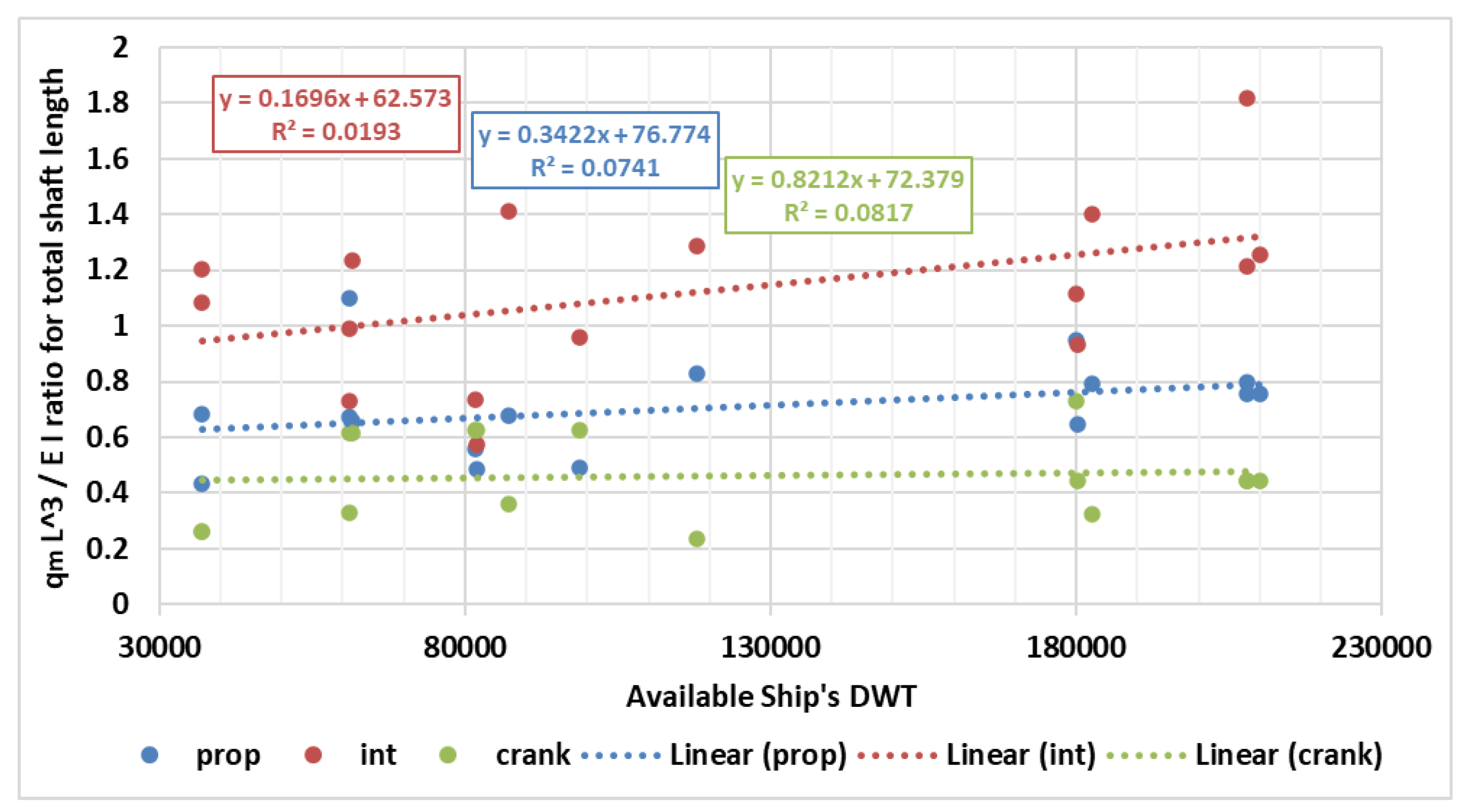
The results revealed that this pivotal ratio exhibits a relatively small standard deviation in the crankshaft section and slightly higher variability in the propeller shaft. However, notably, it displays significantly greater variation in the intermediate shaft segment. This observation underscores that the intermediate shaft part of the shaft arrangement tends to exhibit more substantial variations across different ship sizes and configurations.
To provide a more detailed perspective, Table 8 compiles the average values and standard deviations for this noteworthy ratio, for Propeller, Intermediate and Crankshaft, identified during the analysis of the various shaft arrangements.
With these parameters in mind, a specific characteristic vessel, namely vessel "Bulk Carrier S" has been selected as the exemplar for the application and evaluation of the developed methodology in the ensuing case study.
5.3. Dimensional Analysis—“Bulk Carrier S”
This section addresses the dimensional analysis conducted on the case study vessel, "Bulk Carrier S." This methodology can be broken down into two distinct components: the equivalent shaft modeling and the small-scale journal bearing modeling. Similarity is achieved through the rigorous application of dimensional analysis and the utilization of dimensionless parameters. These analytical tools enable seamless acquisition of knowledge and insights derived from data collected during experiments conducted on the small-scale model within the test rig. This Case Study is a numerical example that includes critical parameters crucial for assessing model-prototype similarity within marine shafting systems. These parameters encompass various factors that influence the system's behavior and are vital for accurate scaled model development.
- Geometric Data Parameters include Shaft Length (L) and Shaft Diameter (D), which influence mechanical properties and structural integrity, respectively.
- Load-Related Parameters cover Shaft Weight (W), essential for load simulation, and External Loads, representing additional forces or moments during operation. Shaft Rotational Speed (ω) is crucial for understanding dynamic response.
- Material Properties Parameters include Modulus of Elasticity (E) for stiffness assessment and Shaft Inertia (I) to gauge resistance to angular velocity changes.
- Support Configuration Parameters encompass Bearing Locations and Vertical Offset, critical for static and dynamic behavior.
Marine shafting systems exhibit complex structural configurations, requiring careful consideration of similarity parameters for scaled replication. Key Scaling Parameters involve creating a full-scale model.
For accurate shaft-line Modeling, several relevant parameters can be extracted from the ship's shaft arrangement plan and other related drawings. These parameters are essential for accurately replicating the shaft arrangement in both actual and scaled models. Some of the key parameters include:
- →
- Shaft Length (L): The total length of the shaft, including the propeller shaft, intermediate shaft, and crankshaft, is a fundamental parameter.
- →
- Shaft Diameters (D): The diameters of the individual shaft sections, such as the propeller shaft, intermediate shaft, and crankshaft, are critical for geometric similarity.
- →
- Bearing Locations: Information about the exact positions of the bearings along the shaft is vital for replicating the support configuration accurately.
- →
- Shaft Material Properties: Details about the material composition of the shaft, including its modulus of elasticity (E), are crucial for assessing structural behavior.
- →
- Shaft Weights: The weights of the different shaft sections provide insights into the load distribution and are essential for load simulation.
- →
- Shaft Rotational Speed (ω): The rate at which the shaft rotates, typically measured in RPM, is important for understanding dynamic behavior.
- →
- Vertical Offsets: Information about any vertical offsets applied to the shaft arrangement aids in replicating alignment conditions.
- →
- Propeller Details: If applicable, details about the propeller, including its diameter, load, bending moment and eccentric trust, are essential for simulating the external loads of the propulsion system.
- →
- Load-Related Parameters: Any other external loads or moments applied to the shaft arrangement, as well as their magnitudes and positions, should be extracted from the drawings.
- →
- Bearings and Bearing Types: Information about the types of bearings used, their sizes, parameters like aspect ratios (e.g., shaft length-to-diameter ratios) and their positions along the shaft.
These parameters collectively provide the necessary data for creating an equivalent shaft-line model that closely mimics the real ship's shaft arrangement. This modeling is essential for understanding and assessing the behavior of the system under different operating conditions.
Having completed an accurate model of the real large-scale asset, it is possible to develop smaller scale models that follow some dimensional similarity, this can be conducted ensuring the following requirements are met. This results in an Equivalent Scaled Model (M) resembling the Real Model geometrically and the dimensional analysis can be formulated according to Eq. (2.3-2.5,3.3-3.5) and Eq. (5) as:
- w is the applied external load
- L is the beam element length and
- lq is the length where uniform beam load is applied
- qm = πD2/4 * ρ, is the uniform beam load for cylindrical beams
- D is the bearing diameter, ρ is the density of the material
- E is the modulus of elasticity of the beam material
- I = πD4 / 64 is the inertia of a cylindrical beam
Figure 8.
“Bulk Carrier S” Original Drawing, Real, Scaled and Equivalent Model.
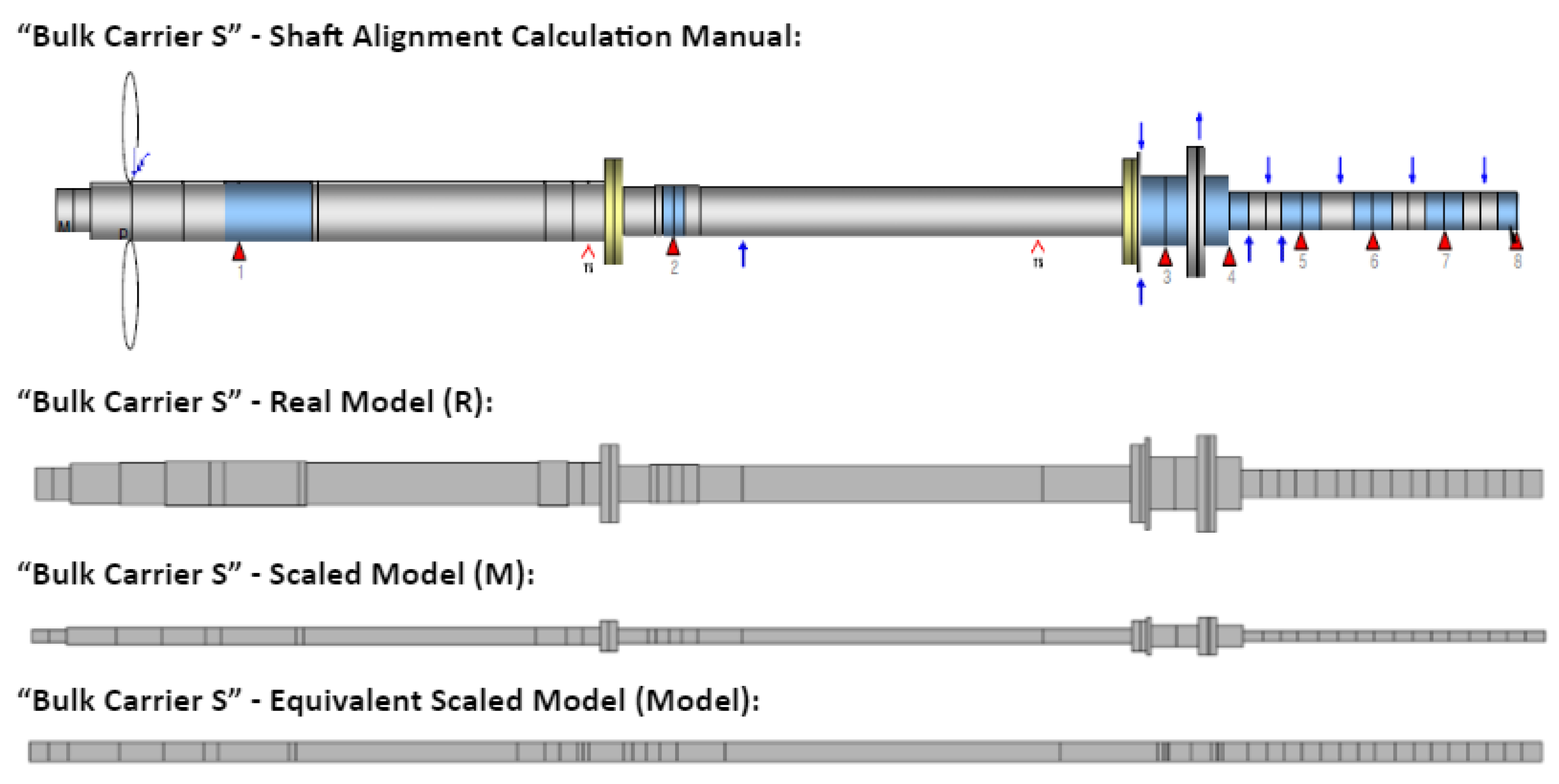
A novel approach is implemented, involving a fixed Modulus of Elasticity (E) and a predetermined fixed shaft diameter (D) at a scaling ratio (n), then ensuring that qmL3 / EI = constant the Length of each equivalent beam element is calculated. This leads to the creation of the Equivalent Scaled Model (Model), affecting the length-to-diameter ratio of beams differently in various shaft sections. Shaft alignment simulations are performed to validate the bearing reaction forces and calculate influence factors, utilizing the “Shaft Alignment Tool” an in-house software that had been developed in the department of Marine Engineering of School of Naval Architecture and Marine Engineering of National Technical University of Athens (NTUA). The “Shaft Alignment Tool” is a beam element solver that enables modeling of the shafting system as a series of Euler beam elements [10,11] and was used to assess both the Real and the Scaled Models, with shaft deflection (UY) estimated both in the Real Model and reverse engineered using the Scale Model data and the Equivalent Scale Model. Discrepancies are observed between the predictions from the simple Scale Model, especially in the aft shaft area, due to the complexity of the system and conflicts in terms of similarity for different beam types (simply supported beams and cantilever beams).
Figure 9 illustrates an application of this scaling methodology, comparing the error in reverse prediction of the Prototype (Real) shaft deflections (UYR) using the Scaled Model (M) and the Equivalent Model (Model) respectively. The details of the beam elements models and the respective calculations for each of the models is included in Appendix. These results showcase the effectiveness of the proposed method to produce an accurate Equivalent Scaled Model, at which one can perform lab experiments and extract important data that can transfer knowledge directly to the actual large-scale application.
Numerical comparisons between the basic Scaled Model and the Equivalent Model are conducted to assess their predictive accuracy for actual shaft deflections in the Real Model. The outcomes are visually depicted in Figure 9, and the essential findings are summarized in Table 9, considering both the average error and the standard deviation of the error.
Based on the outcomes of the numerical analysis, the construction of the shaft model for the test rig aligns with the principles of the Equivalent Scaled Model. Specifically, the shaft-line from the flywheel (just before the aftmost ME bearing) is the focus, simplifying the modeling process by excluding the complex crankshaft area. This decision is rooted in the fact that replicating the crankshaft area in laboratory scale becomes impractical, particularly due to the use of a different motor (usually some induction motor) compared to the two-stroke main engine employed in the real application.
5.4. Scaled Journal Bearing Modeling and Manufacturing
To create an accurate small scale Shafting System Model, a range of bearing-related data can be extracted from the ship's drawings and other related technical manuals. These data points are important for replicating the bearing systems in the scaled model. Here are the relevant parameters:
- →
- Bearing Types: Identify the types of bearings used in the ship's shaft arrangement, such as journal bearings, thrust bearings, or roller bearings. Knowing the bearing type is fundamental for replicating the support mechanisms accurately.
- →
- Bearing Dimensions: Extract information about the dimensions of each bearing, including inner and outer diameters, width, and any specific design features. These dimensions are crucial for fabricating scaled-down bearings.
- →
- Bearing Locations: Determine the precise positions of each bearing along the shaft. This data helps establish the correct support configuration and alignment in the scaled model.
- →
- Bearing Materials: Identify the materials from which the bearings are constructed. The material properties influence bearing performance and should be replicated in the scaled model.
- →
- Bearing Lubrication: If available, gather information regarding the lubrication systems used for the bearings. Details about oil or grease lubrication can aid in simulating bearing behavior accurately.
- →
- Bearing Loads: Extract data related to the loads that each bearing is designed to withstand. This includes radial loads, axial loads, and any moments or forces applied to the bearings.
- →
- Bearing Clearance: Information about the radial bearing clearance is critical for replicating the bearing's operational characteristics.
- →
- Bearing Friction: If available, data associated with the coefficient of friction or the surface properties of the bearings can be essential for modeling purposes.
- →
- Bearing Foundation: Details about where and how the bearings are mounted or secured within the shaft arrangement are necessary for accurate replication systems.
- →
- Bearing Wear: Information regarding expected bearing wear, maintenance schedules, and replacement intervals can inform the modeling of bearing performance over time.
- →
- Bearing Cooling Systems: If applicable, details about any cooling systems integrated into the bearings can be crucial for accurately predicting the operational lubricant viscosity.
By extracting these bearing-related parameters from the ship's drawings and manuals, one can construct a bearing model, which may then be scaled to replicate the system of the original ship's shaft arrangement.
In the pursuit of bearing similarity, the Sommerfeld Number was considered as the most critical metric ensuring that the bearings would function similarly when scaled down. The bearing scaling pertinent to the Case Study was thoughtfully presented in able 6. For that illustration, a specific set of Aft-Stern-Tube-Bearing (ASTB) and Forward-Stern-Tube-Bearing (FSTB) components from the conventional "Bulk Carrier S" were chosen, and all geometric constraints of the small-scale bearings (with a scale ratio of n=18) were preserved.
6. Discussion—Applications
In this study, we have introduced a novel Advanced Scaling Methodology based on pi-theorem for assessing the similarity of marine shafting systems. As we delve into the potential applications and implications of this method, it becomes evident that it holds significant promise for shaping the future landscape of experimental research aimed at exploring the intricate phenomena inherent in the operation of a typical marine shafting system.
Several factors contribute to the appeal of the proposed method, yet it is essential to acknowledge both its advantages and limitations. The utility of this approach is contingent upon the specific problem under investigation, emphasizing the importance of aligning the method with the dimensional parameters most pertinent to the research objectives. The method particularly excels in scenarios necessitating the evaluation, prediction, and assessment of crucial parameters such as the vertical offset of bearings (support points), the longitudinal position of these support points, and the distribution of reaction forces on the shaft line supports when subjected to external loads. Additionally, it proves valuable in identifying different states of the shaft line and offers insights into the load-carrying capacity of the bearings. The proposed equivalent model methodology, tailored for a scaled small-scale shaft line, emerges as a valuable tool in providing information and accurate predictions, particularly in transient loading conditions. For instance, applying a transient load at the overhang edge, simulating the typical operation of a propeller, can be effectively modeled and analyzed.
However, it is crucial to recognize that the method may require further refinements and modifications when confronted with dynamic simulations and phenomena associated with vibrations in the system. These phenomena are intricately linked with the distribution of masses along the shaft-line and the specific geometric properties of the system. In such instances, a scaled geometry is required, which will compromise the accuracy of predictions related to deflections and load. A scaled (but not equivalent) model however, would retain its efficiency in providing valuable insights into the respective eigenvalues and vibration modes of the system.
Moreover, the proposed method holds profound implications for simulation-based data acquisition and the comprehension of common challenges encountered in the traditional design of relatively large marine shafting systems. Specifically, it is a conventional practice to design a model before the large-scale installation and application. However, employing the proposed equivalent model methodology now enables the comparison of shaft-line designs that may be geometrically distinct but share inherent similarities, potentially following the same or very similar patterns in terms of their equivalent shaft-line models. Common features, typically addressed using influence factors, may become more conspicuous in the realm of equivalent models. This insight could be harnessed during the design and optimization process to enhance the reliability of a new system design by transferring knowledge from operation of other existing similar systems of a different scale.
Additionally, this methodology serves as a foundational element for any model or simulation-based assessment tool requiring a common backbone of features to evaluate significantly different designs in terms of exact geometry. In essence, it becomes possible to construct a surrogate model to assess the performance of a specific shaft-line design. Utilizing the dimensional analysis presented in this work, surrogate models can be developed to evaluate the performance of any shafting system design, identifying and leveraging their common features in the equivalent model space. This substantially reduces the required data for training, minimizes the necessary computational power for simulation and data production, and ultimately establishes a benchmark method for comparative performance assessment in marine shafting systems.
7. Conclusions
In conclusion, this paper presents an advanced Pi-Theorem based scaling methodology for the systematic assessment of marine shafting systems. The integration of journal bearing similarity assessment and shaft-line scaling methodology, coupled with advanced dimensional analysis, establishes a robust foundation for the replication and analysis of these systems through scaled models. The proposed scaling methodology ensures both geometric and mechanical similarity by considering key parameters such as shaft length, diameter, weight, loads, rotational speed, material properties, bearing locations, and offsets.
The advanced dimensional analysis, yielding specific non-dimensional ratios, guarantees a close resemblance between real-size systems and scaled lab-models, facilitating meaningful experimentation. The methodology is analytically derived and also validated as an example through numerical simulations in a case study. The comparative analysis conducted demonstrates the effectiveness of the proposed framework for further experimentation.
The proposed equivalent modeling approach has significant implications for future experimental works aiming to enhance the understanding of complex phenomena in marine shafting systems. While the method offers advantages in assessing parameters like vertical offset, longitudinal position of support points, distribution of reaction forces, and the shaft line's different states, it may require additional considerations for dynamic simulations and vibration-related phenomena.
Furthermore, the proposed method holds promise for simulation-based data acquisition aiming at understanding common challenges faced in traditional designs of large marine shafting systems. The ability to compare geometrically different shaft-line designs with inherent similarities enhances the reliability of new systems and contributes to the development of surrogate models for comparative performance assessment. Overall, this work lays a foundation for advancing the efficiency and accuracy of experimentation in the field of marine shafting systems.
Acknowledgments
The research work was supported initially by the Hellenic Foundation for Research and Innovation (HFRI) under the “First Call for HFRI Research Projects to support Faculty members and Researchers and the procurement of high-cost research equipment grant” (Project Number: 2415). Furthermore, this research work was also conducted in the framework of the research Project “sPRISMoID”, titled: “Ship Predictive Intelligent Sensor Model Integrated Digitally” (T2EDK-02405), within the framework of the National Recovery Plan and Resilience “Greece 2.0” funded by the European Union – NextGenerationEU.
References
- E. Buckingham, "On Physically Similar Systems: illustrations of the use of dimensional equations," Physical Review, 4, pp. 345–376, 1914.
- E. Buckingham, "Physically similar systems," Academy of Sciences, 93, pp. 347–353, 1914.
- Korczewski, Z., & Marszałkowski, K. (2021). Energy analysis of the propulsion shaft fatigue process in a rotating mechanical system part III dimensional analysis. Polish Maritime Research, (2), 72-77.
- Z. Korczewski and K. Marszałkowski, "Energy analysis of propulsion shaft fatigue process in rotating mechanical system. Part I. Testing significance of influence of shaft material fatigue excitation parameters," Polish Maritime Research, 2018, Vol.25, Special issue S1(97), pp. 211–217. [CrossRef]
- Z. Korczewski and K. Marszałkowski, "Energy analysis of propulsion shaft fatigue process in rotating mechanical system. Part II. Identification studies – developing the fatigue durability model of a propulsion shaft," Polish Maritime Research, 2020, Vol. 27, 2(106), pp. 120–124. [CrossRef]
- Z. Korczewski, "The conception of energetic investigations of the multisymptom fatigue of the simple mechanical systems constructional materials," Journal of Polish CIMAC, 1/2012, p. 99–108, 2012.
- Zohuri, B. (2017). Dimensional analysis beyond the Pi theorem (Vol. 1). Cham, Switzerland: Springer International Publishing.
- Tan, Q. M. (2011). Dimensional analysis: with case studies in mechanics. Springer Science & Business Media.
- E.S. Taylor, Dimensional Analysis for Engineers. Oxford University Press, 1974.
- Rossopoulos, G. N., Papadopoulos, C. I., & Leontopoulos, C. (2020). Tribological comparison of an optimum single and double slope design of the stern tube bearing, case study for a marine vessel. Tribology International, 150, 106343.
- Theofilis, P., Rossopoulos, G. N., & Papadopoulos, C. I. (2023, March). Solution Space and Optimality Concerns for the Shafting System Alignment of a Typical Bulk Carrier. In SNAME International Symposium on Ship Operations, Management and Economics (p. D021S006R002). SNAME.G.A.
- Zhou, W., Zhao, Y., Yuan, H., & Ren, Z. (2023). Experimental Study on the Effect of Hull Deformation on the Relative Attitude between Shaft and Bearing. Journal of Marine Science and Engineering, 11(10), 1992.
- Zhou, W., Zhao, Y., Yuan, H., & Wang, X. (2023). Study of the Hull Structural Deformation Calculation Using the Matrix Displacement Method and Its Influence on the Shaft Alignment. Journal of Marine Science and Engineering, 11(8), 1495.
- Choi, S. P., Lee, J. U., & Park, J. B. (2021). Application of deep reinforcement learning to predict shaft deformation considering hull deformation of medium-sized oil/chemical tanker. Journal of Marine Science and Engineering, 9(7), 767.
- Vignaux, "Dimensional Analysis in Data Modelling," in: Smith C.R., Erickson G.J., Neudorfer P.O. (eds) Maximum Entropy and Bayesian Methods. Fundamental Theories of Physics (An International Book Series on The Fundamental Theories of Physics: Their Clarification, Development and Application), vol 50. Springer, Dordrecht, 1992.
- Wen, X., Zhou, R., Yuan, Q., & Lei, J. (2020). Coupling Mathematical Model of Marine Propulsion Shafting in Steady Operating State. Journal of Shanghai Jiaotong University (Science), 25, 463-469.
- Jadhav, P. M., Kumbhar, S. G., Desavale, R. G., & Patil, S. B. (2020). Distributed fault diagnosis of rotor-bearing system using dimensional analysis and experimental methods. Measurement, 166, 108239.
- Vizentin, G., Vukelic, G., Murawski, L., Recho, N., & Orovic, J. (2020). Marine propulsion system failures—A review. Journal of Marine Science and Engineering, 8(9), 662.
- Vizentin, G., Vukelić, G., & Srok, M. (2017). Common failures of ship propulsion shafts. Pomorstvo, 31(2), 85-90.
- Rossopoulos, G. N., Papadopoulos, C. I., (2024). AI techniques for evaluating misaligned journal bearing performance: An approach beyond the Sommerfeld number. Proceedings of the Institution of Mechanical Engineers, Part J: Journal of Engineering Tribology, 13506501241232457.
Figure 1.
A simply-supported elastic beam Equilibrium and boundary equations.
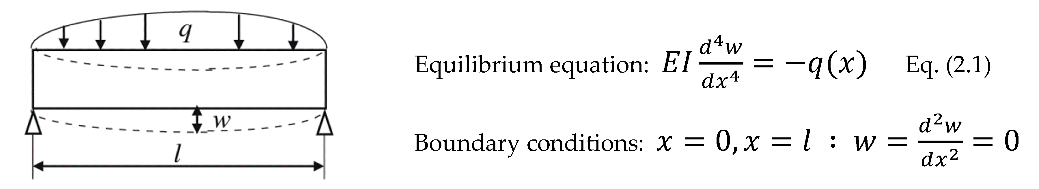
Figure 5.
Results (an example case) for the Reverse prediction of shaft displacement.
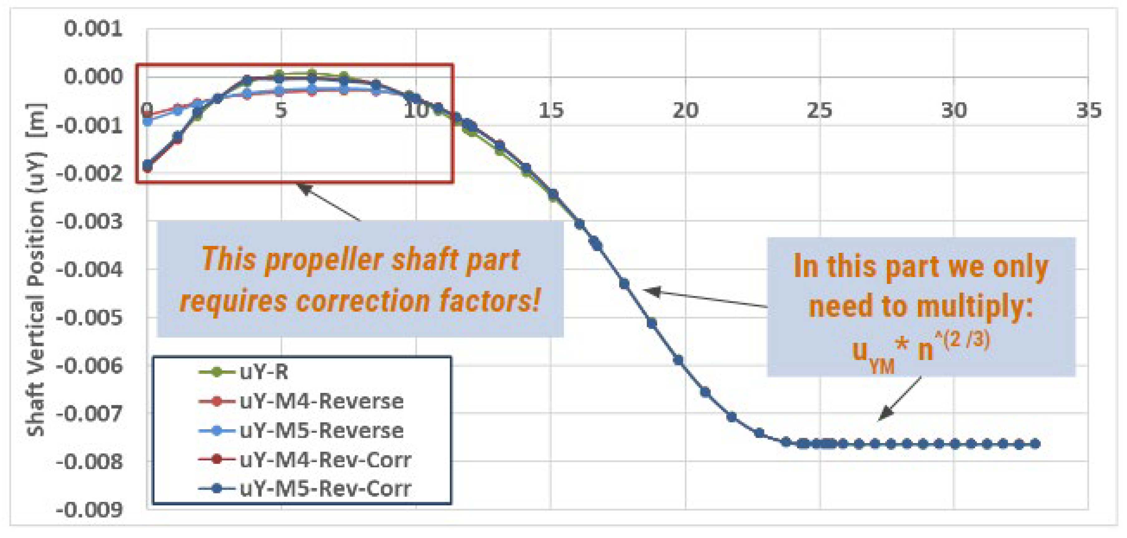
Figure 6.
Various (Shaft Length / Total Shaft Length) Ratios for Bulk Carriers of different DWT.
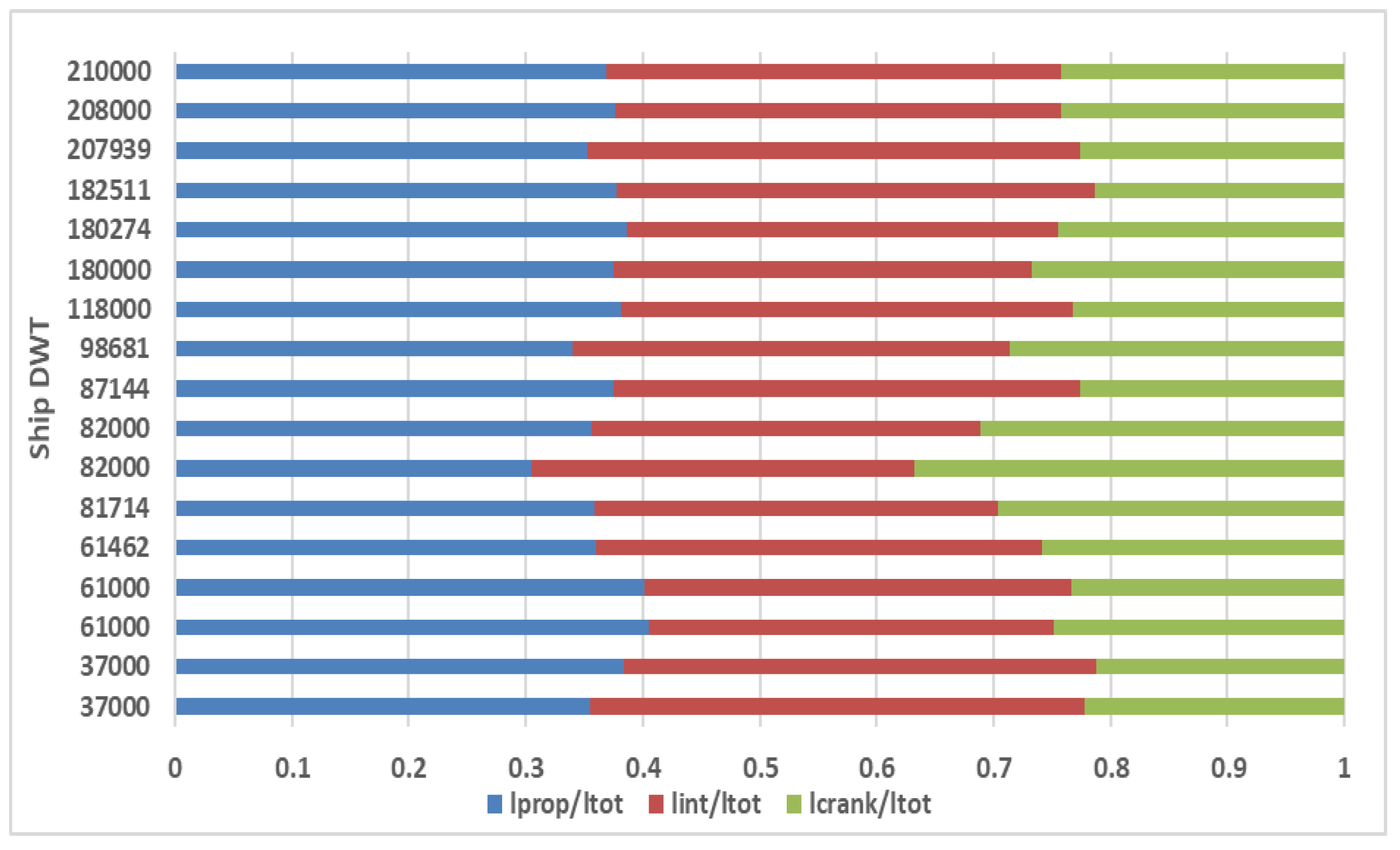
Figure 9.
Scaled Model (M) and Equivalent Model (Model) error Comparison.
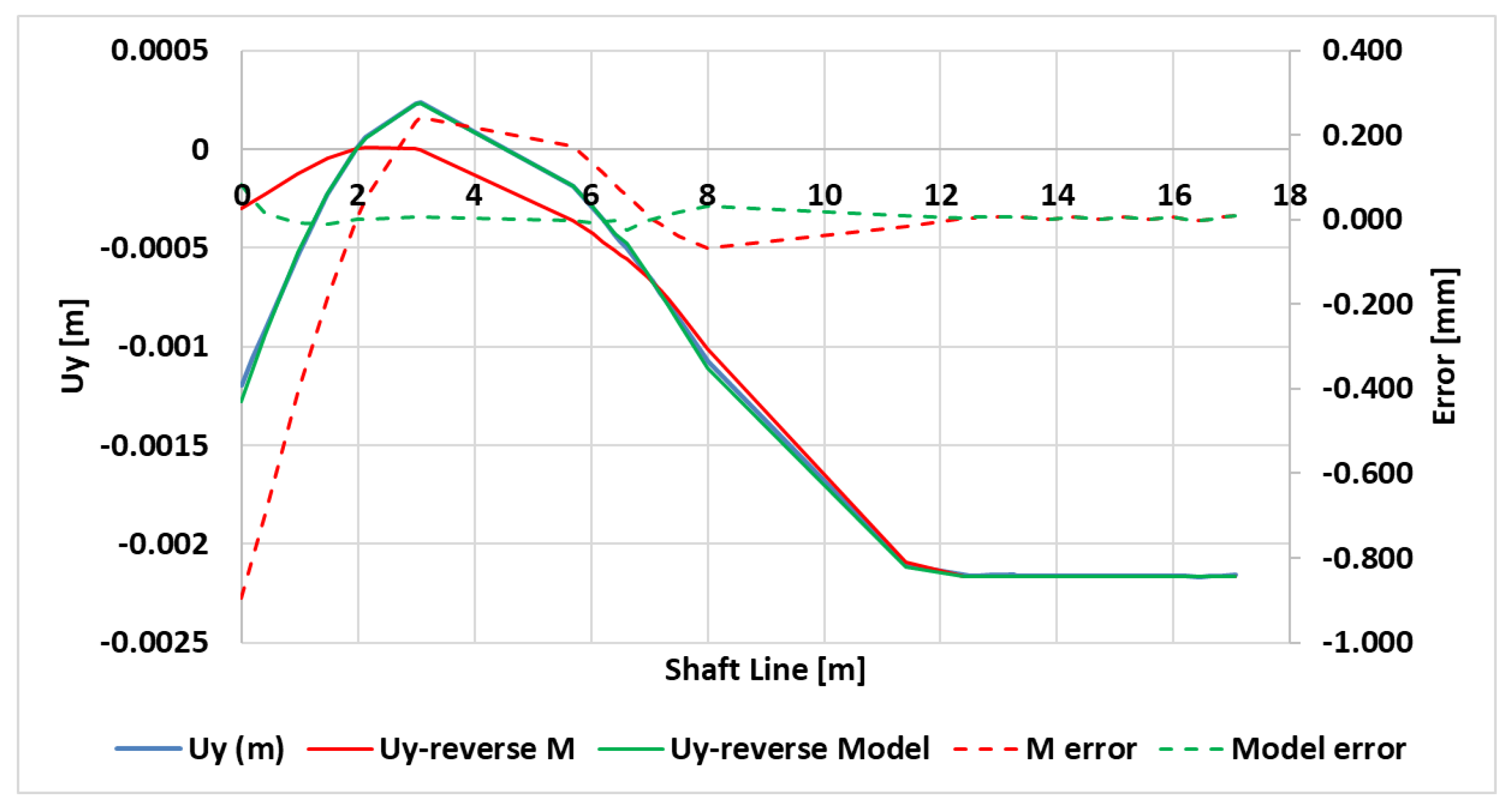

Table 1.
Dimensions of commonly derived mechanical quantities.
| Quantity | Common Symbol(s) | Dimensions | |
|---|---|---|---|
| Geometry | Area | A | L2 |
| Volume | V | L3 | |
| Second moment of area | I | L4 | |
| Kinematics | Velocity | U | LT-1 |
| Acceleration | α | LT-2 | |
| Angle | θ | 1 (i.e. dimensionless) | |
| Angular velocity | ω | T-1 | |
| Quantity of flow | Q | L3T-1 | |
| Mass flow rate | ṁ | MT-1 | |
| Dynamics | Force | F | MLT-2 |
| Moment, torque | T | ML2T-2 | |
| Energy, work, heat | E, W | ML2T-2 | |
| Power | P | ML2T-3 | |
| Pressure, stress | p, τ | ML-1T-2 | |
| Fluid properties | Density | ρ | ML-3 |
| Viscosity | μ | Ml-1T-1 | |
| Kinematic viscosity | ν | L2T-1 | |
| Surface tension | σ | MT-2 | |
| Thermal conductivity | k | MLT-3Θ-1 | |
| Specific heat | cp, cv | L2T-2Θ-1 | |
| Bulk modulus | K | ML-1T-2 |
Table 2.
Generalized journal bearing similarity formulation.
| Prototype | R | h | W | p0 |
|---|---|---|---|---|
| Model | R/n | h/n | W/n | n x p0 |
Table 3.
Dimensions involved in cantilever beam dimensional analysis.
| Quantity | Symbol | MLT |
|---|---|---|
| Applied Force | P | F |
| Deflection | δ | L |
| Modulus of Elasticity | E | FL-2 |
| Beam Radius | r | L |
| Beam Length | L | L |
Table 4.
Model Parameter Ratios.
| Parameter Calculation | |
|---|---|
| Reality | Model |
| Dr | Dm=Dr / n |
| LR | Lm=Lr / n2/3 |
| ER | EM |
| Vertical_DisplacementR | Vertical_DisplacementM = Vertical_DisplacementR / n2/3 |
| ForceR | ForceM = ForceR / n3 |
Table 5.
Average Error of Equivalent scaled Model for different scale ratios (n).
| Model 4 Reverse | Model 5 Reverse | |
|---|---|---|
| n (shaft diameter ratio) | 69 | 27.6 |
| Dpropeller (at ASTB) | 10 mm | 25 mm |
| Average Relative Error % | 0.009 | 0.010 |
| Standard Deviation of Error | 0.0496 | 0.0560 |
Table 6.
Bearing parameter scaling with Sommerfeld Number.
| L/D | D [m] | L [m] | R [m] | c [m] | μ [Pa s] | N [RPM] | P [N] | Somm | |
|---|---|---|---|---|---|---|---|---|---|
| R1 | 1 | 0.45 | 0.45 | 0.225 | 0.00045 | 0.05 | 90 | 100,000 | 0.03797 |
| R2 | 2 | 0.45 | 0.9 | 0.225 | 0.00045 | 0.05 | 90 | 500,000 | 0.01519 |
| M1 1:18 | 1 | 0.025 | 0.025 | 0.0125 | 0.00026 | 0.07 | 1440 | 63.9 | 0.03797 |
| M2 1:18 | 2 | 0.025 | 0.05 | 0.0125 | 0.00026 | 0.07 | 1440 | 319.6 | 0.01519 |
Table 7.
Average values and standard deviations for various noteworthy ratios.
| Average | St.Dev. | |
|---|---|---|
| Lprop/Ltot | 0.368 | 0.023 |
| Lint/Ltot | 0.377 | 0.028 |
| Lcr/Ltot | 0.255 | 0.040 |
| Dprop / Dfl_prop | 0.617 | 0.066 |
| Dint / Dfl_int_aft | 0.506 | 0.057 |
| Dint / Dfl_int_fore | 0.431 | 0.055 |
| Dcr / Dfl_cr | 0.355 | 0.044 |
| Lfl_prop / Lprop | 0.015 | 0.003 |
| Lfl_int / Lint | 0.014 | 0.002 |
| Lfl_cr / Lcr | 0.015 | 0.008 |
Table 8.
qmL3/EI ratio across the Propeller, Intermediate and Crankshaft of ships with varying DWT.
| qmL3/EI | Average | St.Dev. |
|---|---|---|
| Prop | 0.705 | 0.167 |
| Int | 1.122 | 0.296 |
| Crank | 0.461 | 0.154 |
Table 9.
Average Error of Equivalent Model (Model) and Scaled Model (M).
| Model | M | |
|---|---|---|
| n (ratio) | 20.4 | 20.4 |
| Dpropeller (ASTB) | 25 mm | 25 mm |
| Average Error % | 0.005 | -0.039 |
| St.Dev. of Error | 0.015 | 0.216 |
Disclaimer/Publisher’s Note: The statements, opinions and data contained in all publications are solely those of the individual author(s) and contributor(s) and not of MDPI and/or the editor(s). MDPI and/or the editor(s) disclaim responsibility for any injury to people or property resulting from any ideas, methods, instructions or products referred to in the content. |
© 2024 by the authors. Licensee MDPI, Basel, Switzerland. This article is an open access article distributed under the terms and conditions of the Creative Commons Attribution (CC BY) license (http://creativecommons.org/licenses/by/4.0/).
Copyright: This open access article is published under a Creative Commons CC BY 4.0 license, which permit the free download, distribution, and reuse, provided that the author and preprint are cited in any reuse.


