Submitted:
03 November 2025
Posted:
04 November 2025
You are already at the latest version
Abstract
This study explores the feasibility of constructing a microwave kiln for artisanal ceramics using accessible materials and homemade susceptors. Two modified microwave ovens (18L and 50L) were equipped with insulation and susceptors to achieve temperatures up to 1280°C. Susceptors were fabricated from silicon carbide (SiC) and magnetite (Fe₃O₄) powders via microwave-assisted reactive sintering. Magnetite-poor susceptors (SiC/Fe₃O₄ > 2 by weight) demonstrated excellent durability, maintaining stable thermal performance over multiple cycles. In contrast, magnetite-rich susceptors (SiC/Fe₃O₄ ∼ 1) exhibited high initial efficiency and the ability to control redox conditions but degraded significantly after 10–15 cycles due to partial melting. The microwave kiln achieved significant time savings, completing the ramp up of the firing cycles in 1 hour, compared to 8-10 hours in conventional kilns. Energy consumption per litre was comparable to large electric kilns but significantly lower than small ones. The fired ceramics, including porcelain and earthenware, showed excellent mechanical and aesthetic qualities, with glazes performing well even at lower temperatures than recommended. The study highlights the advantages of microwave heating, such as faster processing, energy efficiency, and the ability to control redox conditions, which mimic traditional gas-fired kilns. The developed susceptors are cost-effective and easy to manufacture, making this approach accessible to craftspeople and amateurs. While magnetite-rich susceptors enable redox control, their limited lifespan requires further optimization. This work demonstrates the potential of microwave kilns for artisanal ceramics, offering flexibility, efficiency, and quality comparable to traditional methods, with promising applications for unique or small-scale production. Future research should focus on refining susceptor durability and validating redox control effects on ceramic glazes.
Keywords:
microwave firing
; ceramics
; susceptors
; reactive sintering
; BCC-Iron
; silicon-carbide
; magnetite
; ferrosilicon
; redox
1. Introduction
1.1. The Place of Microwave Heating in Ceramic Firing Methods
Since their invention after World War II, microwave heating and cooking have become a universal tool, widely adopted in homes and catering. This led to the mass production of low-cost, easy-to-use domestic appliances [1]. Industrially, the technology is also extensively used for low and medium-temperature applications like drying and sterilisation [2,3,4].
At higher temperatures, microwave energy has proven effective for tasks such as reducing iron ore [5,6,7]. For sintering ceramic materials and oxides, microwave heating offers clear advantages over traditional methods. It is a well-established fact that it improves diffusion kinetics and densification, allowing these processes to be completed at a much faster rate and at a lower temperature than conventional sintering [8,9,10]. This combination of faster heating and improved densification dramatically divides processing time by an or two order of magnitude [10,11] and reduces significantly energy consumption [8,9].
Consequently, high-temperature microwave sintering has been developed for manufacturing high-quality technical ceramics [10,11,12] with significant added value for advanced applications in the medical, space, and military sectors. In the consumer sector, however, high-temperature microwave applications are rare. They are almost exclusively limited to dental applications for producing small prostheses (zirconia) in very small kilns (1/4–1/2 liter). For utilitarian or artisanal ceramics, which represent a large market, there is currently no available equipment that uses only microwave energy.
Despite this, a large number of laboratory studies over the last 30 years have demonstrated the clear benefits of microwave heating for both test specimens and standard-sized objects [13,14,15,16,17,18,19,20,21]. Nevertheless, the technologies used for firing utilitarian ceramics remain based on traditional kilns heated by an external source—often powered by fossil fuels. These energy-intensive and time-consuming techniques immobilise equipment and human resources.
This surprising conservatism in heating techniques for artisanal ceramics, especially when faced with the extraordinary potential of microwave technology in terms of energy, time, and quality gains, has been noted by many authors. One interpretation [22] is the difficulty of modelling wave-matter interactions, particularly for large objects. However, experimental and theoretical work from the last ten years has consistently shown that it is possible to successfully manufacture ceramic tableware using microwave heating [16,17,18,19,20,21,23].
1.2. Microwave Heating: Principles and Current State of Knowledge
- General Principles
Microwave heating is fundamentally different from traditional heating processes. In conventional methods, an external source (like oil, gas, or electrical resistance) transfers energy to a material primarily through radiation and conduction. In contrast, microwave heating generates heat internally within the material itself. This occurs at an atomic level as microwaves interact with the material’s molecules.
When a material containing polar molecules is exposed to microwave energy, the electromagnetic radiation causes these molecules to rotate, which generates heat. This phenomenon is known as dielectric heating. A polar molecule, such as water, has a distinct positive and negative charge, giving it an electric dipole moment.
- High-Temperature Heating of Ceramics with Microwaves
A material’s ability to self-heat when exposed to microwaves is referred to as its ability to couple with or suscept to the electromagnetic radiation. Conversely, a material that allows microwaves to pass through without heating is transparent, while one that blocks them is reflecting. A ceramic material that undergoes dielectric heating is called a susceptor.
Achieving high-temperature conditions for sintering materials using direct microwave heating presents several challenges. The most common applicators, which operate at low frequencies (2.45 GHz), often struggle to efficiently couple with many materials at room temperature, making initial heating difficult. Ceramics, with their non-homogeneous properties (such as dielectric permittivity and losses), complicate this interaction. For large ceramic pieces, uneven heating can lead to thermal gradients, causing cracks. Additionally, rapid heating can induce thermal stresses, porosity, and localised hot spots, which may lead to a catastrophic temperature runaway [24,25].
To overcome these issues, hybrid heating techniques have been developed. These methods combine direct microwave heating with a secondary heat source, often a susceptor material with high dielectric loss at low temperatures. A susceptor absorbs microwave energy and quickly reaches high temperatures, transferring heat to the ceramic sample through conventional mechanisms like radiation. Once the sample reaches a high enough temperature, its own dielectric loss increases, allowing it to begin absorbing microwaves and heating internally.
This hybrid approach, also known as “susceptor-assisted microwave heating,” offers a dual heating mechanism: the susceptor heats the material from the surface, while the microwaves heat it from the center. This results in more uniform heating compared to direct microwave heating, where the center typically becomes hotter than the surface. The reduced heat loss from the surface, aided by the susceptor, further contributes to maintaining thermal homogeneity during the process [10,11,22,26]. In practice, this involves placing various forms of susceptors (tubes, plates, rods, etc.) near the piece to be heated [26,27].
- High-Temperature Microwave Kiln Design
Microwave heating cavities are metal enclosures designed to maximise energy transfer efficiency by containing and reflecting microwaves to create standing waves. These cavities can be multi-mode or single-mode, which influences the distribution of the electromagnetic field. Multi-mode cavities, such as those in a standard microwave oven, allow waves to propagate freely throughout a large volume, while single-mode cavities constrain the field, making them more efficient for small samples and precise control.
The electric field distribution within a multi-mode cavity is complex, depending on the material’s geometry, the microwave emission characteristics, and the material’s evolving dielectric properties [25]. Non-uniform field patterns and hot spots caused by a static applicator design can lead to uneven heating and thermal runaway. To improve heating uniformity and efficiency, multi-mode applicators often use mode stirrers—mobile metallic elements that modify the electromagnetic field—and rotating turntables to change the sample’s position within the cavity [28,29].
- Advantages of Microwave Heating
Despite the challenges, a major advantage of microwave heating is the spectacular time savings, which can be 5 to 10 times faster than conventional heating for achieving comparable or even superior product quality [10,14,18,26].
Since the late 1980s, when microwave ovens were first used for ceramics [9], extensive research has demonstrated the benefits of this heating method. The work of Tiago Santos and his colleagues at the University of Aveiro, Portugal, stands out as some of the most successful in manufacturing everyday ceramic objects with microwaves. Their latest article (23) provides a comprehensive review of this research, highlighting the following key benefits:
- Significant reduction in sintering time and energy consumption.
- Lower firing temperatures (50–75 °C lowest than traditional methods) to achieve similar results.
- Faster and more uniform densification of materials.
- Comparable or superior mechanical properties of microwave-fired products compared to those fired conventionally.
- Challenges still exist in accurately measuring sintering temperatures, as thermocouples and pyrometers have limitations. However, analysing the final colour of the ceramics, glazes, and decals can serve as a useful tool for assessing and mapping the firing temperature of the finished pieces [23].
1.3. Aim of the Article
The performance of microwave heating, particularly its time-saving benefits for firing traditional ceramic pieces, makes it a compelling option for craftspeople or amateurs producing small quantities or unique pieces. The absence of commercial devices for this purpose makes it tempting to build such a system using readily available materials, especially given how common microwave appliances are.
The purpose of this article is to demonstrate that it is feasible to build and use a controllable and configurable microwave kiln—one with adjustable temperature, heating rates, and duration—for firing traditional artisanal or artistic ceramics. We will show that this can be done using materials and equipment available from standard retailers. This article will also highlight the great flexibility of microwave heating for artisanal ceramic production, even in a less-than-perfectly configured kiln.
We will tackle the most difficult questions of development of susceptors that can be made by the craftsperson using mineral powders in their own workshop. The thermal, physical, and mineralogical behaviours of these susceptors will be described in an initial analysis. We will also evaluate their potential impact on the kiln’s oxidation-reduction properties. To illustrate the process, some examples of firing earthenware, porcelain, and enamels will be presented. Finally, we will compare the advantages and disadvantages of this method to a conventional kiln.
2. Materials and Methods
2.1. The Microwave Kilns
Two commercial microwave ovens were modified to serve as ceramic kilns. The first was a small, 18-liter, 2.45 GHz multi-mode microwave. It featured a single 800W magnetron but had no mode stirrer and its turntable removed to accommodate insulation. To allow observations and pyrometer measurements, an 18 mm diameter shutter was installed through the door and oven insulation. Although small and prone to hot spots, this oven (Figure 1-(a)) was invaluable for developing solutions for insulation, magnetron cooling, susceptors sintering, and firing procedures.
The second, larger kiln was built from an ageder, 50-liter, 2.45 GHz multi-mode microwave (from 1997). To increase power and improve field homogeneity, two additional microwave power units separated from their cavity were attached: one on top (from a 1993, 700W unit with a pyramidal horn) and a third on the left side (from a 2005, 700W unit). This created a powerful, triple-magnetron setup (Figure 1-(c)). The maximum electrical power is 3.8 kWh, corresponding to approximately 2200 W of microwave emission power. The electrical consumption of microwaves was measured by consumer watt-meters installed on each of the microwaves. The insulation of this large oven was designed to use refractory materials that combine high microwave transparency with low density, such as alumina based insulating materials, such as the porous alumina blanket, fiber wool, insulating fiberboard (26). Following these recommendations, the insulation was installed using a combination of low-density bio-soluble fibre insulation (1400 °C) for the outer layer and JM23 refractory bricks (1300 °C), sliced into 1cm thick, plates for the inner part. A 1cm thick slice of a JM26 brick (1400 °C) served as the kiln floor. The insulation thickness was adjusted to meet different firing temperatures (8 cm for 1100 °C and 12 cm for 1300 °C), maintaining the microwave cavity wall temperatures around 100 °C and providing a free volume of 6.5 L and 3 L, respectively. The volume could be changed by adding or removing JM23 plates.
To prevent magnetron overheating, both kilns were equipped with external ventilation. The small kiln had a fixed 1.2m3/mn fan, while the large one had an adjustable 0-14m3/mn system to cool the three magnetrons and the cavity walls. The original power and timer controls were kept, allowing for manual and individual operation of each magnetron. Possible microwave leaks have been verified by an RS-2G detector.
These two ovens were fitted with a type K shielded thermocouple linked to digital thermometers for temperature measurements and recording by a computer. The temperatures were also measured by a commercial digital infrared pyrometer either through the shutter of the small microwave or after opening the oven door. The pyrometer has an accuracy of 3% from 800 to 1600 °C and a measuring spot of 12mm and 19mm at 20cm and 30cm respectively.
Remarkably, this rustic, recycled equipment proved highly durable, withstanding over 150 firing cycles up to 1100 °C and beyond, each lasting several hours. Only a single capacitor failure was recorded.
2.2. Susceptors
2.2.1. Susceptor Considerations
The success of hybrid heating largely depends on the susceptor’s design. Susceptors must provide sufficient pre-heating without excessively shielding the ceramic piece from microwaves. Therefore, their quantity and placement must be carefully chosen to ensure that microwaves can still reach the material [26]. This is particularly important when a susceptor fully surrounds the sample.
To make it easy to adjust the susceptor quantity and placement, we opted to develop solid, wafer, or rod-shaped susceptors that could be placed on the kiln floor or vertically along the walls [27]. While industrial susceptors are typically made from SiC or MoSi2 rods [26,30], these materials are not commercially available to the public. Instead, we focused on common, low-cost powdered minerals like silicon carbide (SiC), magnetite (Fe₃O₄), and carbon (graphite, coal) [26,30,31].
SiC is an excellent dielectric material for microwave absorption, known for its low density and high thermal and chemical resistance. However, its absorption performance can be highly variable, depending on its crystalline structure (polytype) and morphology [31]. For this reason, SiC often requires modification to enhance its absorption, which can include adding other dielectric or magnetic materials like magnetite, or increasing its porosity to promote multiple reflections [31].
Magnetite (Fe₃O₄), a member of the spinel ferrite class, also excels at microwave absorption due to its complex permeability and permittivity. However, for efficient absorption, magnetite is often most effective when they have nano- to submicrometre size [32].
Since a common method for creating a solid from a powder is high-temperature sintering by reactive solid or liquid phase sintering using microwave [33,34]. The use of additives to achieve reactive sintering makes it possible to avoid the extreme conditions required to sinter silicon carbide [33,34,35]. The additives reduce sintering temperatures and improve densification while also affecting the high-temperature mechanical and thermal properties of SiC ceramics [34], Thus, we explored this process to manufacture our susceptors. Although iron, introduced in the form of Fe2O3, is not known to be an effective additive for sintering silicon carbide with conventional heating [35], we tested a mixture of a powder of submicrometre magnetite and a powder of micrometre SiC. In just 10 minutes in the microwave, the mixture was fully sintered, exhibiting excellent mechanical properties. Tests showed that the best performance was achieved with 20% up to 45% magnetite by weight. Beyond this range, the mixture was susceptible to thermal runaway, which would episodically destroy the sample.
2.2.2. Susceptor Manufacturing: Materials and Procedure
Based on preliminary test results, a series of susceptors were manufactured using silicon carbide (SiC) and magnetite (Fe₃O₄) powders in various compositions and shapes. The SiC powder, a common abrasive material, had grain sizes ranging from 10 to 100 µm (140 to 1000 MESH).
The magnetite powder was sourced from the Hymag’in start-up and was synthesised from metallurgy ferrous scraps [36]. It featured a fine grain size distribution, ranging from nanometric to microscopic (60–3000 nm), with an average size of around 800 nm (Figure 2). Tests confirmed that this nanoscale or submicroscopic size was crucial for effective microwave interaction; coarser, other commercially available magnetites (from a pigment supplier and LKAB) remained inert. To enhance microwave absorption, especially at low temperatures, alumina (Al2O3) and silica (SiO2) sands were added. At room temperatures, these materials are largely transparent to microwaves [26], acting as a porous structure that improves absorption capacity and allows waves to penetrate the susceptor more easily [31]. As temperatures rise, the changing dielectric loss around 800 °C of alumina allows them to increase the susceptor’s overall absorption [9,26]. The Fontainebleau silica sand (200 µm) was purchased from a ceramics supplier, and the alumina corundum sand (250 µm) was an air eraser compound. In use, these sands also played the role of a solid matrix during the reactions undergone by the susceptors during the heating cycles. Pure graphite powder was also used in one test.
The powders were mixed with demineralised water and lightly ground by hand in a porcelain mortar. They were then cast into various shapes using silicone moulds or moulds carved from JM26 refractory bricks (Figure 3). For the silicone moulds, 5% clay (fraction <2µm from Wyoming bentonite) was added to improve handling after drying. Sintering was performed in the small microwave for shorter susceptors and in the large kiln for longer ones. In total, approximately 50 susceptors were created and tested in over 150 firing experiments. The main types of susceptor manufactured in this study are listed in Table 1. The magnetite-based susceptors, can be classified into two groups, one with a low Fe₃O₄ wt content (MS type, SiC/Fe₃O₄ ranging from 1.9 to 3.1) and a group with a higher content (MSS and MAS type, SiC/Fe₃O₄ between 1-1.3).
2.2.3. Macroscopic Susceptor Characterisation method
The behaviours of the susceptors were evaluated by visual observation them in situ during sintering. We used an optical pyrometer to measure the susceptor’s surface temperature and a shielded type K thermocouple to measure the furnace temperature.
To quantify the susceptors’ thermal power, each one was placed in a small, 100 cm3 insulated chamber inside the small microwave’s 800 cm3 kiln. A thermocouple, positioned 0.6 cm above the susceptor’s surface, continuously recorded the furnace temperatures (Figure 4 (f)). The susceptor’s temperature, measured by a pyrometer immediately after heating, was in average 100 °C+/- 40 °C (40 samples) higher than the thermocouple reading.
Based on these measurements, the average thermal power (W/gram) of each susceptor was calculated using its maximum temperature, heating time, mass, and the specific heat values of its components (Table 2).
2.2.4. Microscopic Susceptor Characterisation Method
The goal of the microscopic study was to understand the evolution of these materials, their influence on the redox conditions, and the temperatures at which transformations occur.
To study the mineral transformations within the susceptors, two types of preparations were made for scanning electron microscopy:
Slices of the main body of the susceptors which were glued, thinned, and polished on an aluminium support.
Sampling of the melted structures: This included bubbles and films that formed on the susceptor surfaces. The samples are glued onto an aluminium backing for their direct observation.
These observations were complemented by X-ray diffraction (Cu radiation) performed on crushed powder samples with a Rigaku XMAX 2500 rotating anode X-ray diffractometer at Laboratoire de Géologie de l’Ecole Normale Supérieur in Paris (LGENS) and Siemens D5000 diffractometer at Institut des Sciences de la Terre (ISTerre) in Grenoble.
Scanning electron microscopy (SEM) investigations were conducted on carbon-coated polished sections susceptors for imaging with backscattered electrons and energy dispersive X-ray spectroscopy (EDXS) mapping. A probe current of 150 pA at 15 kV was used for EDXS mapping that allowed semi-quantitative compositional analysis. Two different SEM were used: a SEM-FEG TESCAN CLARA (PtME MNHN) and a SEM-FEG Zeiss SIGMA (LG-ENS). The microscope at LGENS had an EBSD (Electron Backscatter Diffraction) Oxford instruments device for crystallographical determinations.
The ageing of the susceptors was studied by SEM characterisation on samples chosen immediately after sintering, after two heating cycles (recent) and after more than ten heating cycles (aged).
A firing cycle consisted of a temperature increase to a maximum plateau (heating) followed by a cooling phase. The average heating time was about 60 minutes (with a maximum of 90 minutes), while cooling took between 2.5 and 4 hours (Figure 4).
3. Results
3.1. Macroscopic Evaluation of the Properties of Different Susceptor Formulations
The results are presented in Figure 5, Figure 6 and Figure 7 and Table 3. After sintering and use, they showed a clear decrease in thermal power over time. Susceptors made of SiC alone degraded the most, while those containing magnetite retained their performance better.
- Silicon Carbide (SiC) Alone
Susceptors made solely of silicon carbide (with grain sizes of 10-60 µm) coupled unevenly with microwaves, leading to inconsistent temperatures both between and within samples (Figure 5). These susceptors, even with the addition of 10% bentonite, never fully sintered and remained powdery after heating. The best performance was observed with intermediate grain sizes (600 MESH, or 23 µm), with an average absorption power of approximately 3 W/gram during sintering. However, this power rapidly declined to 1.5 W/gram after just 30 minutes of use (Table 3, Figure 7). These characteristics did not allow them to be used further. .
- Silicon Carbide + Magnetite (MS) with SiC/Fe₃O₄ ratio = 1,9-3.1
These susceptors consistently coupled strongly with microwaves, achieving uniform temperatures across and within samples (Figure 5). Sintering temperatures ranged from 800-930 °C. The best performance was observed with intermediate grain sizes (220-500 MESH, 63 to 28 µm). Susceptors with 40 wt% magnetite performed better than those with 22%, particularly in temperature uniformity.
Successful sintering occurred on the very first heating, resulting in robust, shock-resistant susceptors. The average absorption power of these low iron susceptors was remarkably stable, decreasing only slightly from 4.5 W/gram to 4 W/gram over 800 minutes of use (Table 3, Figure 7). This exceptional heating power allowed the kiln to reach nearly 800 °C in just 420 seconds, far surpassing the 250 °C achieved with the best SiC-only susceptors (Figure 6). After repeated use, even at temperatures up to 1300 °C, the MS susceptors retained their shape and appearance, though their surface colour shifted to a grayish-red, suggesting the oxidation of black iron oxide (FeO or Fe₃O₄) to reddish hematite (Fe2O3) (Figure 8 a).
- Silicon Carbide + Magnetite + Silica or alumina (MSS, MAS) with SiC/Fe₃O₄ ratio = 1-1.3
These susceptors also coupled strongly with microwaves, reaching sintering temperatures comparable to the formulations having a high SiC content. However, their very high initial absorption power (4.7 W/gram) steadily decreased with use, eventually matching the low performance of SiC-only susceptors (1.4 W/gram) after 1300 minutes of cumulative heating (Figure 7). This decline in performance was also reflected in their heating power (Figure 6, curves 4-5-6).
After prolonged use, although keeping their shape, their appearance changed, showing increased surface porosity and fusion bubbling. During one firing of porcelain at 1300 °C, a MAS susceptor with alumina sand developed a melted, glassy film on its surface. The colour of these susceptors remained a deep black with a slight sheen, suggesting a more reducing environment that preserved the reduced iron oxides (Figure 8).
- Other Formulations
Two other compositions were tested: one with magnetite and silica sand, and another with magnetite, graphite, and SiC. Both initially heated well but could not sustain the high temperatures. The magnetite and silica sample remained powdery, and both samples oxidized, turning red as the magnetite converted to hematite and the graphite burned away. These formulations were not used further.
The simple, accessible manufacturing process developed here successfully produced batches of magnetite-based susceptors of sufficient quality to fire ceramics with apparent temperature homogeneity in a modestly sized kiln (Figure 9). The susceptors less rich in Fe₃O₄ (SiC/Fe₃O₄ >=1.9) showed excellent durability by keeping both their physical and thermal properties after sintering. Despite an apparent decrease in the performance over time and with an alteration of their appearance, the richest in Fe₃O₄ (SiC/Fe₃O₄ = ~1) still demonstrated the ability to quickly rise to high temperatures to achieve porcelain firing.
3.2. Microscopic Susceptor Characterisation
3.2.1. Descriptions of Mineral Transformations in Susceptors
The mineral transformations observed according to the main formulations and according to the cumulative duration of heating, including the first sintering, is presented in Table 4. The image descriptions and presentation of crystallographic and chemical data for the main mineral transformations and their evolution during the heating cycles from the first sintering step are shown in Figure 10, Figure 11, Figure 12, Figure 13, Figure 14 and Figure 15.
- Sintering: At the microscopic scale, mineral transformations are characterized by a total disappearance of the initial magnetite within the first minutes of sintering, leading to mineral reactions with silicon carbide. During the initial 7-minute sintering at 850 °C, magnetite transforms into three distinct phases: (1) iron droplets, 100 to 200 µm in size, typically located within the largest pores; (2) hematite dispersed throughout the matrix; and (3) micrometric granules of ferrosilicon (gupeiite, Fe3Si) associated with a layer of cristobalite, formed at the periphery of the silicon carbide grains (Figure 10).
Upon continued sintering at 1100 °C for an additional 18 minutes, these mineral transformations intensify. The iron droplets develop a polycrystalline structure characteristic of body-centered cubic (BCC) iron. Concurrently, the ferrosilicon layers surrounding the initial silicon carbide grains thicken and extend, while the SiC grains themselves decrease in size. A brief SEM image analysis suggests a 40-50% reduction in SiC grain volume, with the average grain size diminishing from an initial 44µm to 25-30µm after heating. These granular structures, consisting of a silicon carbide core surrounded by ferrosilicon, are bonded together by cristobalite. This matrix of cristobalite is locally intergrown with ferrous olivines (fayalite) associated with newly formed magnetite (Figure 11 and Figure 12). The SEM-EBSD images and analyses characterize the various iron-silicon phases present in the matrix surrounding the SiC grains (Figure 13) and, at times, within single crystals (Figure 14). In addition to the gupeiite (Fe3Si) observed after the initial 850 °C sintering, we also identify xifengite (Fe5Si3), ferrosilicite (FeSi2), and an unnamed iron-silicon phase (Fe11Si5).
EBSD maping analysis quantify the total proportion of ferrosilicon in the matrix to around 15,7%. Within the matrix and in the large zoned crystals, the relative proportions of Fe5Si3, Fe3Si, and FeSi2 are respectively 43 and 48%, 39 and 40%, and 18 and 11% (% of identified phases). Other phases identified in the EBSD mapping include SiC (47%), SiO2 (cristobalite, 24%), Fe₃O₄ (magnetite, 7.3%), and Fe2SiO4 (fayalite, 6.1%). The percentage of unindexed points, likely corresponding to porosity, is 53% (Figure 13, Table 5). This value is comparable to the porosity calculated for samples containing 25% magnetite (Table 1)
- Low Fe₃O₄ content susceptor evolution. During successive heating cycles of ceramics up to 1300 °C, the mineralogy and structure of the magnetite-poor susceptors (SiC/Fe₃O₄>2) undergo moderate changes, as does their external appearance, irrespective of the formulation (with or without added quartz or alumina) (Table 4).
In most cases, the iron droplets found within the porous structure are partially or completely replaced by an iron oxide, typically hematite. An exception is observed in MAS-type susceptors, where the iron oxide is magnetite instead. In MS and MSS susceptors, Fayalite (Fe2SiO4) are locally replaced by pseudomorphs composed of microscopic fibers or particles of hematite embedded in cristobalite. A glass with the composition of fayalite is also observed locally in the highest-temperature samples. Hercynite (FeAl2O4) appears in the MAS susceptors, specifically in association with corundum meaning that alumina grains are involved in mineral reactions.
The data reveal a near-halving of total ferrosilicon (from ∼16% to 7% of EBSD identified occurrences), characterised by a sharp drop in gupeiite (Fe3Si) but a relative rise in ferrosilicite (FeSi2). Concurrently, the proportion of fayalite increases significantly, from 6% to 12%. Phases such as SiC, magnetite, and cristobalite maintain stable concentrations. The combined porosity and glassy phase—represented by areas without defined EBSD crystal orientation (Figure 15)—shows a modest reduction from 53% to 48% after cycling.
- High Fe₃O₄ content susceptor evolution. As the transformation of their external appearance suggested, the mineralogy of the susceptors with a high Fe₃O₄ content during the heating cycles of the ceramics shows strong modifications.
The replacement of SiC grains by ferrosilicon and cristobalite is more intense. Visually, we can estimate that approximately 75% of the SiC grains have disappeared after the first two heating cycles (Figure 16). During the first two heating cycles at 1100 °C, large areas composed of cristobalite, containing microscopic hematite crystals, envelop and infiltrate the regions where the SiC and ferrosilicon aggregates are still well preserved (Figure 16). However, these structures disappear and were not observed in the aged susceptors. In the following successive heating cycles, the silicon carbide gradually disappears, until it is completely gone after 10 to 15 cycles. This is accompanied by a significant development of siliceous phases, most commonly cristobalite and locally tridymite, in the MAS-30 susceptor shown Figure 8e.
In this series of iron rich susceptors, the amount of metallic phases decrease with time, more intensely in the siliceous MSS susceptors than in the aluminous MAS ones. Iron disappears completely, while the ferrosilicon phases persist as dispersed particles within the matrix, in the form of Xifengite (Fe5Si3). Ferrosilicates, such as fayalite, present in the initial heating cycles, decrease or disappear in susceptors used at high temperatures, coinciding with the appearance of glassy phases in the susceptor matrix. These Fe-Si-O glasses are sufficiently abundant to exude and flow to the surface of the susceptors where they recrystallize (Figure 8 c, d, e) as magnetite and cristobalite (Figure 17). In the MAS alumina susceptors, aluminous phases such as hercynite (FeAl2O4) crystallize around the corundum grains, while mullite fibers (Al6Si2O13) appear within the cristobalite matrix or in a glass of Si-Al-Fe-O composition, which could be result to the melting of ferrocordierite (Al4Si5Fe2O6).
- The transformations observed in these magnetite-based susceptors appear to be of great diversity and complexity. These are transformations that are typically seen in steel slags and ferro-silicon furnace [38]. The mineral assemblages are highly significant indicators of the extreme temperature and redox conditions these objects have undergone, and therefore provide crucial insights into the environment within the microwave kiln
3.2.2. Interpretation of Mineral Transformations: Evaluation of Temperature and Redox Conditions
The most striking observation is the disappearance of magnetite during sintering, with the pseudomorphic replacement of silicon carbide grain outer rim by ferrosilicon at temperatures between 850 °C and 950 °C. This result are consistent with experiments [39,40] conducted at 800-1100 °C on mixtures of iron and silicon carbide in air or in the presence of argon and hydrogen. In these studies, silicon carbide was shown to decompose with the formation of the more thermodynamically stable ferrosilicon (Fe3Si) and the precipitation of graphite.
Other experiments [5,6] conducted to investigate the feasibility of producing cast iron from iron oxide and carbon using microwaves as an energy source have shown that pig iron can be obtained in air with yields of approximately 40%.
To understand the behavior of magnetite alone when exposed to 2.45 GHz microwaves, a simple experiment was conducted by placing a few grams of magnetite powder in a sealed silica tube and heating it in a small microwave oven. Within seconds, the powder reacted, causing a sudden temperature rise and a strong gas emission until the tube exploded. The resulting post-cooling sample (Figure 18) shows a black core containing electrically conductive particles surrounded by a red hematite crown. This suggests a strong reduction of magnetite to iron and reduced oxides with the emission of oxygen gas, i,e, Fe3O4 => 3Fe+2O2. This oxygen would be responsible for the tube explosion and for the oxidation of the sample’s outer rim during cooling. Another observation made in this study is the constant appearance of a flame above all susceptors containing magnetite and silicon carbide during the first few minutes of sintering, which suggests the emission of a combustible gas (Figure 18).
All these observations, combined with the presented mineralogical data and literature references [5,6,40,41,42] suggest that during sintering, the reaction between magnetite and silicon carbide in the susceptor is as follows:
(R1) 2SiC+Fe₃O₄→Fe3Si(s)+2CO(g)+SiO2(s)
And in air, the hot CO gas burns according to:
(R2) 2CO+O2→2CO2
The observed mineral transformations in the susceptors are interpreted through reference to the phase diagrams of the Fe-Si and FeO− SiO2 systems (Figure 19 and Figure 20) and [41,42,43,44]. Temperature conditions measured during sintering, ranging from 850 °C to 950 °C, are consistent with the formation of BCC iron and gupeiite (Fe3Si) via solid-state transformations. The subsequent appearance of higher-temperature and more siliceous ferrosilicon compounds, such as xifengite (Fe5Si3) and ferdisilicite (FeSi2) in susceptors heated to around 1100 °C aligns with their stability fields (Figure 19) in a system necessarily very low in oxygen. During successive heating cycles, the disappearance of gupeiite corresponds to the re-equilibration of the system around its average composition (R1, Figure 19). This re-equilibration occurs either by solid-state recrystallization at temperatures below 1210 °C or by fusion-recrystallization at the highest temperatures [41,42]. The preferential nature of the latter mechanism is strongly suggested by the correspondence between the compositions of the ferrosilicon compounds ( Fe11Si5, Fe5Si3, and FeSi2) and the compositions of the two eutectics in the Fe−Si system, centered at 0.3 and 0.7 mole fraction of Si (Figure 19).
The silica phase resulting from reaction (R1) is nearly always cristobalite. Since its stable equilibrium is typically maintained above 1470 °C, its presence in this context necessitates it being considered metastable. In contrast, tridymite, which is stable under the studied temperature range (850 °C to 1300 °C), was identified by X-ray diffraction in only two samples (MAS-30) (Table 4).
Olivines (fayalite) are compatible with temperatures below 1190 °C, which marks their melting temperature (Figure 20) (43, 44). Above this temperature, in the presence of metallic iron and silica, ferrous olivines melt to produce a highly iron-rich ferrosilicate liquid [43]. The degree of melting is composition-dependent: the greater the iron content and the closer the system is to the eutectic composition, the more extensive the melting. Consequently, the most iron-rich susceptors (SiC/Fe₃O₄=1, such as MSS and MAS-30-35) can experience up to 60% melting, while samples with the lowest iron content (SiC/Fe₃O₄=3, such as MS−22) are only affected to the extent of 23% (Figure 20).
In addition to temperature, the co-existence of olivine minerals, metallic phases (BCC iron, ferrosilicon), and silica dictates extremely low oxygen partial pressures P(O2), on the order of 10−12−16 atmospheres below 1300∘C [43]. These highly reducing conditions are consistent with reaction (R1), which involves the decomposition of silicon carbide (SiC) and the production of CO gas. However, maintaining such reducing conditions is challenged by the presence of oxygen in the furnace atmosphere (P(O2)=0.21 atm). In susceptors with a lower iron content, where the destabilization of SiC is less pronounced, or in susceptors not subjected to extensive heating above 1100 °C, the highly reduced zones are interspersed with more oxidised zones. These zones are characterised by the presence of hematite replacing BCC iron, or associated with SiO2 instead of fayalite, which corresponds to P(O2) values between 10−10atm at 1100 °C or 10−6 atm at 1300 °C [43]. These more oxidizing conditions significantly shift the system’s melting point to above 1450 °C [43], further limiting the melting potential of these iron-poor susceptors (SiC/Fe₃O₄>2) consistent with the visual observation of melting features (Figure 8a).
In contrast, in susceptors with a higher iron content, where the destabilization of SiC is more advanced and continues with each heating cycle, reducing conditions are maintained at an intermediate level. This leads to the formation of stable magnetite- SiO2 asssemblages under P(O2) of approximately 10−8 to 10−10 atm between 1100-1300 °C. Under these conditions, the melting temperatures are between 1250 °C and 1350 °C [43]. This corresponds well to the appearance of fusion structures on the surface of these susceptors heated around and above 1250 °C (Figure 8 c, d, e).
While the MS 22-25 series susceptors (low iron content) correspond well to the requirements for hybrid ceramic heating at temperatures around 1300 °C, the significant melting observed in the high-iron susceptors above 1200 °C is surprising for their intended use in firing ceramics. However, the observation of a recrystallized melt structure composed of magnetite and silica, which indicates very reducing conditions at the surface of the susceptors exposed to the furnace atmosphere, implies that this atmosphere itself was also significantly reduced. The ability to create a reducing atmosphere, low in oxygen, within a ceramic kiln is a crucial feature [46]. This is necessary to achieve specific effects in glazing and is generally achieved by controlling the combustion process in gas-fired kilns. In electric kilns used for ceramics, the atmosphere is typically oxidising.
Table 6 presents the physical transformations (changes in solid and gas volumes) observed in the susceptors during sintering, based on their composition. For susceptors with the highest iron content, the analysis also extends to their use in successive heating cycles, which leads to the complete consumption of silicon carbide (SiC). During these cycles, the high-temperature generation of significant volumes of reducing gases (CO and CO2)—amounting to several litres under standard conditions in each cycle—is notable. Given the furnace volume of 4−6 litres, this gas production is sufficient to ensure the furnace atmosphere remains strongly reducing, even throughout the cooling phase.
The use of iron-rich susceptors, which can partially melt at relatively low temperatures (~1200-1260 °C) in reducing conditions [43], potentially allows for control of the redox potential in the furnace, but this approach also limits their lifespan.
3.3. Added Values of the Studied Susceptors
In conclusion, the susceptors studied here, based on a mixture of silicon carbide and magnetite powder, provide a powerful and versatile toolbox for ceramic firing.
The magnetite-poor susceptors (SiC/Fe₃O₄>2) demonstrate excellent durability, reproducibility, and thermal efficiency up at least to 1300 °C, positioning them on par with conventionally used susceptors for hybrid microwave heating [26].
Conversely, the magnetite-rich susceptors (SiC/Fe₃O₄∼1) also exhibit excellent initial thermal efficiency but undergo progressive degradation, limiting their lifespan to ten to fifteen heating cycles. However, they offer a unique ability to control the oxygen reduction level within the furnace. The addition of silica or alumina sand, while finally not necessary for microwave absorption, provides, in fact, an effective structural framework, maintaining the susceptor’s integrity during partial melting reactions above 1200 °C.
Both types of susceptors are exceptionally easy and quick to fabricate using readily available, low-cost materials. It depends mainly on the price of the submicroscopic magnetite powder, the price of the other components being negligible, that is currently approximately €0.4/g. This means that a 150g batch of low-iron susceptors, required for ceramic firing in a 6 liter kiln, currently costs around €15 with a lifespan of several dozen firing cycles, whereas for those with a higher iron content with redox capacities, the cost will be around €21 for a lifespan of 10 to 15 cycles. This price can be compared to the €2.50 currently charged by ceramicists per firing cycle for the aging of heating elements in a standard electric kiln.
4. Examples of application: Ceramic Firing and Glazing
4.1. Ceramic Materials and Firing Procedure
The materials used for the ceramic pieces were all commercial products available in ceramic material stores in France: White and Red Earthenware Clays: These had a recommended firing temperature of 1050 °C for biscuit and at 1020-1060 °C for glazing. Porcelain Pastes: These had a recommended firing temperature of 950 °C for the degourdi and 1280-1340 °C for vitrification. Some of the pieces fired were made by professional ceramists.
The distribution and organisation of the pieces in the oven was done in a way that optimised space for maximum filling. The susceptors were moved to accommodate the free spaces, ensuring they did not touch the susceptors but remained at a distance of 2 to 3 cm (Figure 1e). Mixing ceramics of different compositions in the same load was avoided to achieve the most homogeneous response possible to the microwave interaction.
The heating method relied on the original manual controls of each modified three magnetron microwave oven. Power adjustment was done manually by operating the timer, which regulates the on/off cycles of the magnetron. Typically, this provided 7 or 8 power levels. Temperatures were either recorded by a computer or noted manually, and the heating rate was adjusted manually based on these temperature readings.
The firing curves and power settings were different for the initial firing of raw pieces compared to the second firings for glazing or porcelain.
- First Firing (Raw Pieces): A gradual ramp-up was used, varying from 6 to 10 °C/min up to 200 °C. Power was then increased progressively to full capacity around 600 °C following a ramp up of about 25 °C/min (Figure 4 a). In the large microwave, this was done in activating successively the three magnetrons with their power increasing progressively at each time: the first was turned on, followed by the second when the first reached full power (around 200-250 °C), and finally the third was switched on when the second reached full power (around 400 °C), with full power for the third typically reached around 600 °C. From this point, heating was done at full power without regulation until the maximum temperature was reached. A plateau could then be maintained by re-adjusting the power.
- Second Firing (Glazing/Porcelain): For small pieces in the small microwave, the power was gradually increased up to 150 °C before switching to full power (Figure 21). In the large microwave, with its larger pieces, the power increase was more gradual, reaching full power around 600 °C over 20 minutes (Figure 4b).
Cooling was done naturally by opening the microwave door and removing the first layer of insulation from the oven opening.
Susceptors were placed upright against the walls of the kiln. A typical arrangement involved a long susceptor (7-10 cm) in each corner and a small one (4-6 cm) in the middle of the faces. This amounted to a total of 6 to 7 susceptors, with a total weight of 140-170 grams, providing a potential thermal power of 500 to 700 W. For the large kiln, which had a raw piece load of 300 to 700g, the weight of the susceptors represented 25% to 50% of the total load. The choice of susceptors was made on their size and weight to obtain the best possible heat distribution. Homogeneous susceptor formulations were used in the same firing.
4.2. Material Limitations
The initial difficulty lay in accurately interpreting the thermocouple readings. The literature frequently reports significant temperature gradients between the thermocouple measurement and the temperature experienced by the ceramic part (or measured via alternative methods) [16]. To mitigate this disparity and ensure a more accurate reading of the ceramic temperature, the most effective solution was to place the thermocouple directly inside the piece being fired, when possible or very close if not.
For firings above 1250-1270 °C in the large oven, a second difficulty arose in finding a material that, for iron-rich susceptors, prevents them from coming into contact with the furnace walls. This material must also be transparent to microwaves and chemically inert with respect to the susceptors. Indeed, the liquids resulting from the partial melting of the iron richest susceptors react with the silica and alumina content of the insulating refractory material, causing localised melting. This fusion behavior incidentally confirms that the system was under sufficiently reductive conditions to lower the fusion temperature to approximately 1300 °C, a significant reduction compared to the 1380 °C typically observed under atmospheric oxygen pressure for the SiO2-FeO-Al2O3 system [44].
In this case, while the ceramic pieces were successfully fired without defects, the oven’s insulation is thus damaged at these temperatures around 1300 °C (Figure 22).
4.3. Some Achievements of Large Handicraft Pieces
During this exploration of microwave-fired ceramics, many artisanal pieces were successfully made and fired. While small pieces (less than 7-8 cm) were consistently easy to work and fire, the main challenge in artisanal ceramics is producing larger pieces, commonly up to at least 20 cm in their largest dimension. This study testifies that this could be quickly and successfully accomplished in a microwave oven.
Figure 23 shows a selection of relatively large earthenware pieces fired and glazed using this method. In each case, both firings—the first for the raw unglazed piece and the second for the glazing—were perfectly executed, in terms of both physical quality and the expected colours.
4.3.1. Ceramic Quality
As far as can be judged without proper equipment, the quality of the fired pieces to the touch and appearance seems to have excellent mechanical properties. The quality can also be appreciated by the excellent sound of the pieces, earthenware sounding like porcelain and also by visual assessment carried out by professional ceramists (P. Lemaitre and C. Combes). Two X-ray diffractograms (Figure 24) made on porcelain fired at 1230 °C and earthenware fired at 1005 °C show their excellent crystallinity. In the porcelain, the ratio between mullite and quartz is around 50%, and the high proportion of glass corresponds well to the proportions described in the literature for porcelain sintered at 1250 °C in a microwave oven [20]. For earthenware fired at 1005 °C, the absence of hydrated phases and carbonates, along with the presence of diopside which appears from gehlinite at 1000 °C and forsterite at 1000 °C [47,48], is consistent with these temperatures.
4.3.2. Glazing Quality
Glazing is a critical step for ceramists, and this work confirms that it can be successfully and quickly accomplished in a microwave kiln, as reported in the literature [23]. Aesthetically, the enameling produced was of very good quality, achieving the expected effects when applied correctly (Figure 23, Figure 25).
Tests were conducted to compare the temperatures measured by a thermocouple in the kiln with the glaze manufacturer’s recommendations. The results showed that the acceptable temperature range for a glaze can be extended by 50-100 °C towards lower temperatures without significant changes in color or texture. The extent of this range depends on the specific glaze, with some being more tolerant than others. For example (Figure 25): - Crystal Turquoise: This glaze, with a recommended range of 1020-1060 °C, showed a consistent appearance between 920 °C and 1010 °C and was already vitreous at 840 °C; - Panzy: Recommended for 1020-1100 °C, this glaze did not change its appearance between 960 °C and 1050 °C and was vitreous from 880 °C; - Coral Red: This glaze performed best within its recommended temperature range. The behavior of the glazes was found to be consistent across the three different types of earthenware clay used. These findings support the hypothesis that microwave sintering extends the temperature range transformations to lower temperatures [23].
4.3.3. Time and Energy Saving
In traditional ceramic firing, typically used in the craft sector, the ramp up lasts between 8 and 11 hours in conventional electric kiln, depending on the materials and uses. In industry, ramp up times are generally shorter, around 3-4 hours, using different processes [46].
In contrast, the firing time of ceramics in a microwave kiln is measured in minutes or in seconds, which is a significant advantage. A typical 3.8 kWh microwave kiln, like the one described, consumes an average of 500 Wh/L for firing earthenware in a 6 litres volume to 700 Wh/l for firing porcelain in a 4.8-liter configuration (Figure 24). These values are very close to those of the microwave developed by T. Santos and colleagues [23] having a power of 6 kWh for 8 l of useful volume. The consumption relative to the volume in an electric conventional kiln decrease with the volume from around 2400 Wh/L in 10-liter kiln to 500Wh/l in a 1m3 one for a complete firing cycle (values calculated from public data of kiln manufacturers and ceramists). Relative to the volume, the energy consumption of a microwave ceramic kiln around 500 to 700 Wh/L is thus equivalent to that of a large conventional electric kiln and significantly lower than that of a small one. This efficiency of small microwave kiln means that a ceramist doesn’t have to wait, some time half month or more, for a large kiln to be full before firing a single piece. This is particularly beneficial for as example: - On-demand production in tourist areas, - Apprenticeships, where a piece can be fired and completed within a day or two, - Firing unique pieces or conducting tests.
5. Discussion
The primary objective of this study—to demonstrate the feasibility of constructing an easily accessible microwave kiln for artisan ceramic firing—was successfully achieved. The resulting kiln, built from readily available components, is suitably sized for craft production, capable of firing and glazing earthenware, stoneware and porcelain up to 1280 °C with satisfactory results. Its practical utility is underscored by its efficiency: the ability to fire pieces up to 21×21×12 cm within hours represents a substantial time and convenience advantage over conventional kilns. Although the current mechanical and electrical setup requires optimisation—specifically through a centralised, automated control system and better-calibrated power regulation—a strong correlation between heating rate and electrical power suggests that precise control could effectively compensate for potential temperature measurement inaccuracies (Figure 26). However, the temperatures derived from the analysis of mineral reactions on the susceptors did not reveal any inconsistencies with the temperatures measured using thermocouples or optical pyrometry with a commercial device.
Beyond the practical construction, a key scientific challenge was the development of an inexpensive, efficient, and durable susceptor for hybrid microwave heating. This challenge led to the investigation of SiC-Fe₃O₄ composite materials. Optimal compositions were identified, leading to two distinct products: a high-durability susceptor (Fe₃O₄≤25 wt% of SiC content) comparable in performance to commercial SiC susceptors; and a highest Fe₃O₄ content one (40 to 50 wt% of Fe₃O₄) with limited durability but unique redox properties.
The intriguing behavior of the magnetite-rich susceptors, which exhibited evidence of partial fusion, revealed a significant insight into the material’s function. The physicochemical conditions attained within these susceptors mimic those found in industrial processes like steel slag or ferrosilicon production [38] or in environments with a high reducing power, such as those found in the Earth’s mantle or in meteorites [49,50]. These are characterised by extremely low oxygen environments and liquidus temperatures as low as 1200 °C for the iron-rich Fe-Si-Al-O system.
In the susceptors, Fe₃O₄ acts as a “catalyst,” initiating the reactive sintering of SiC due to its strong microwave absorption. During this process, silicon carbide is consumed and replaced by ferrosilicon and silica as carbon burn away. The synergistic combination of dielectric loss (SiC) and magnetic loss (Fe/ferrosilicon), generated by eddy currents within the metallic cores [51,52], maintains the material’s thermal performance.
Incidentally, the partial melting and subsequent expulsion of molten material and gaseous products from the susceptors in high magnetite variants facilitates an interface between the internal susceptor environment and the furnace atmosphere allowing the furnace to potentially operate under reducing conditions. While this partial melting compromises long-term durability, the resulting reducing environment is a highly desirable asset for specific ceramic glazes and body compositions (46).
Future research must focus on validating this reducing atmosphere for the whole kiln hypothesis through detailed glaze analysis (23, 46). Furthermore, the observation that the Fe₃O₄ additive enables the reactive sintering of SiC at low temperature (850 °C–950 °C) and low pressure (1 bar) to form a silicate binder represents an incidental but highly promising avenue for developing new, low-energy SiC based material manufacturing processes.
6. Conclusions
This work has demonstrated the possibility for a ceramic craftsman or amateur to use a microwave oven to fire earthenware and porcelain up to approximately 1280 °C. The system’s operation is similar to that of a conventional microwave.
With ramp up firing cycles taking only 1 hours, the time savings are considerable. Despite a reduced volume, the energy consumption per object is equivalent to that of a large kiln, offering a flexibility previously unknown in ceramics. This allows for the finished object to be obtained soon after its design.
The process is exceptionally efficient, allowing a ceramist to prepare a piece in the morning, fire it before lunch, and remove it after coffee, thereby demonstrating extraordinary ease of use and a significant time-saving advantage over traditional kilns.
The results and difficulties encountered align with those described in the literature, both in terms of the remarkable quality of the finished products and the challenges in understanding the actual temperature conditions they experienced (23). It is surprising that, despite a lack of precise temperature and power control, the results were consistently excellent. This suggests that the ceramic piece, rather than the kiln, might be controlling the firing process.
The research conducted to create susceptors from readily available materials led to the development of components with unexpected capabilities. Not only do they provide efficient heating, but they also have the capacity to reduce the atmosphere of the kiln. This latter ability, which still needs to be fully demonstrated on a kiln-wide scale, could represent a new advancement for ceramic firing using electricity.
Funding
This research received no external funding and was done with private founds.
Acknowledgments
The author extends sincere gratitude to several individuals and institutions for their invaluable contributions to this work. We are deeply indebted to Sylvain Bernard (CNRS, Museum of Natural History, Paris) and Damien Deldicque (École Normale Supérieure, Paris) for generously granting access to their electron microscopes and providing their decisive assistance in operating the equipment. Special thanks go to Nathaniel Findling for her technical assistance at ISTerre, and to Fabrice Brunet (CNRS, ISTerre) for his careful review of the initial draft of this paper. We also thank the members of the start-up Hymag’in in Grenoble—Camille Crouzet, Phillipe le Bouteiller, and Mathieu Bertrand—for their patient listening and insightful discussions regarding the susceptors, and for providing the magnetite powders. Our appreciation goes to Mathieu Goffé (CNRS, Strasbourg) for his assistance with the bibliography and electronics. Special thanks are reserved for Pierre Lemaitre, former Professor of Ceramics at Ecole Supérieure des Arts Appliqués Duperré à Paris, for his valuable advice and encouraging appraisal of the ceramic pieces produced. Finally, we express our sincere gratitude to ceramist Caroline Combes (Au Tour de la Terre, St Denis d’Oleron, France) for supplying the earthenware pastes and glazing powders, and for her dedicated work in producing the ceramic pieces used in the firing experiments.
Conflicts of Interest
The author declare no conflicts of interest.
References
- Edgar, R.H.; Osepchuk, J.M. Consumer, Commercial, and Industrial Microwave Ovens and Heating Systems. In Handbook of Microwave Technology for Food Applications; Datta, A.K., Anantheswaran, R.C., Eds.; Marcel Dekker: New York, NY, 2001; pp. 215–275.
- Schiffmann, R.F. Microwave processes for the food industry. In Handbook of Microwave Technology for Food Applications; Datta, A.K., Anantheswaran, R.C., Eds.; Marcel Dekker: New York, NY, 2001; pp. 299–353.
- Guo, Q.; Sun, D.W.; Cheng, J.H.; Han, Z. Microwave processing techniques and their recent applications in the food industry. Trends Food Sci. Technol. 2017, 67, 236–247. [CrossRef]
- Zhang, H.S.; Chen, M.Q.; Fu, B.A.; Li, Q.H. Evaluation on microwave drying of waste paper towel with multi-magnetron and mode stirrer. DRYING TECHNOLOGY 2021, 39, 882–895. [CrossRef]
- Martins da Silva, L.; Eugênio, T.F.; de Medeiros, G.A.; de Castro Medeiros, R.G.; de Freitas, P.G.M.; de Castro, J.A. Evaluation of the Use of Microwave Energy on The Reduction of Iron Ore and Steelmaking Mill Scale Composite Self-Reducing Mixtures. Materials Research 2022, 25, 1-7. [CrossRef]
- Sugihashi, A.; Kinoshita, T. Development of Microwave Heating Process for Feedstock for Iron Production. Technical Report NIPPON STEEL & SUMITOMO METAL TECHNICAL REPORT 2019, 121. [CrossRef]
- Colombini, E.; Papalia, K.; Barozzi, S.; Perugi, F.; Veronesi, P. A Novel Microwave and Induction Heating Applicator for Metal Making: Design and Testing. Metals 2020, 10, 676. [CrossRef]
- National Research Council. Microwave Processing of Materials; The National Academies Press: Washington, DC, 1994. [CrossRef]
- Clark, D.E.; Sutton, W.H. Microwave Processing of Materials. Annu. Rev. Mater. Sci. 1996, 26, 299–331.
- Singh, S.; Gupta, D.; Jain, V.; Sharma, A.K. Microwave Processing of Materials and Applications in Manufacturing Industries: A Review. Materials and Manufacturing Processes 2015, 30, 1–29. [CrossRef]
- Oghbaei, M.; Mirzaee, O. Microwave versus conventional sintering: A review of fundamentals, advantages and applications. J. Alloys Compd. 2010, doi:10.1016/j.jallcom.2010.01.068.
- Karayannis, V.G. Microwave sintering of ceramic materials. In Proceedings of the 20th Innovative Manufacturing Engineering and Energy Conference (IManEE 2016), IOP Conf. Series: Materials Science and Engineering, Location of Conference, Country, Date of Conference; IOP Publishing, 2016; 161, 012068. [CrossRef]
- Menezes, R.R.; Souto, P.M.; Kiminami, R.H.G.A. Microwave hybrid fast sintering of porcelain bodies. Journal of Materials Processing Technology 2007, 190, 223–229.
- Lyra, G.P.; Santos, V.; Agnolon Pallone, E.M.J.; Gagedschmidt, H.; Kiminami, R.A.; De Santis, B.C.; Rossignolo, J.A. Microwave hybrid fast sintering of red clay ceramics. Int J Appl Ceram Technol. 2021, 18, 705–715.
- Menezes, R.R.; Souto, P.M.; Kiminami, R.H.G.A. Microwave sintering of ceramics. Part I: Fundamental aspects. Cerâmica 2007, 53, 1–10. [CrossRef]
- Santos, T.; Hennetier, L.; Costa, V.A.F.; Costa, L.C. Microwave versus conventional porcelain firing : Temperature Measurement. Journal of Manufacturing Processes 2019, 41, 92-100. [CrossRef]
- Santos, T.; Gomes, C.S.F.; Santos, N.F.; Costa, V.A.F.; Costa, L.C. Global insight into microwave stoneware firing: Crystallochemical transformations. Ceramics International 2022, 48, 21492–21501. [CrossRef]
- Santos, T.; Hennetier, L.; Costa, V.A.F.; Costa, L.C. Global insight into microwave stoneware firing: Macro and microstructural changes. Int J Appl Ceram Technol. 2019. [CrossRef]
- Santos, T.; Costa, L.C.; Hennetier, L.; Valente, M.A.; Monteiro, J.; Sousa, J. Microwave processing of porcelain tableware using a multiple generator configuration. Applied Thermal Engineering 2013, 50, 677–682. [CrossRef]
- Santos, T.; Gomes, C.S.F.; Costa, V.A.F.; Costa, L.C. Microwave Versus Conventional Porcelain Firing: Greenware to Biscuit Crystallochemical Transformations. Journal of Manufacturing Science and Engineering 2021, 143, 121001-1. [CrossRef]
- Santos, T.; Hennetier, L.; Costa, V.A.F.; Costa, L.C. Using Microwave Radiation for Porcelain Tableware Sintering. Progress In Electromagnetics Research Symposium Proceedings 2015, 939-943.
- Aman, B.; Acharya, S.; Reeja-Jayan, B. Making the Case for Scaling Up Microwave Sintering of Ceramics. Adv. Eng. Mater. 2024, 26, 2302065. [CrossRef]
- Santos, T.; Hennetier, L.; Costa, V.A.F.; Costa, L.C. Temperature Assessment Through Decal Color in Microwave-Fired Porcelain. J. Manuf. Mater. Process. 2025, 9, 213. [CrossRef]
- Chaix, J.-M.; Bouchet, R.; Bouvard, D.; Fabre, T.; Garnault, T. A Viewpoint on Hot Spots in Microwave Sintering and Flash Sintering. Advanced Engineering Materials 2023, 25, doi : 10.1002/adem.202201742.
- Santos, T.; Costa, L.C.; Valente, M.; Monteiro, J.; Sousa, J. 3D Electromagnetic Field Simulation in Microwave Ovens: a Tool to Control Thermal Runaway. Proceedings of the COMSOL Conference 2010 Paris; 2010.
- Bhattacharya, M.; Basak, T. A review on the susceptor assisted microwave processing of materials. Energy 2016, 97, 306–338. [CrossRef]
- Ngamkiatpaisan, A.; Hankoy, M.; Kitiwan, M.; Keawprak, N.; Tunthawiroon, P. A Study on SiC Susceptor Configuration for Microwave Hybrid Heating. Suranaree Journal of Science and Technology 2023. [CrossRef]
- Plaza-González, P.; Monzó-Cabrera, J.; Catalá-Civera, J.M.; Sánchez-Hernández, D. Effect of Mode-Stirrer Configurations on Dielectric Heating Performance in Multimode Microwave Applicators. TRANSACTIONS ON MICROWAVE THEORY AND TECHNIQUES 2005, 53, 1699. [CrossRef]
- Ye, J.; Lan, J.; Xia, Y.; Yang, Y.; Zhu, H.; Huang, K. An approach for simulating the microwave heating process with a slow-rotating sample and a fast-rotating mode stirrer. International Journal of Heat and Mass Transfer 2019, 140, 440–452. [CrossRef]
- Kirby, B.W. Alternative Crucibles for U-Mo Microwave Melting. PNNL-26479, 2017.
- Liu, C.; Yu, D.; Kirk, D.W.; Xu, Y. Electromagnetic wave absorption of silicon carbide based materials. RSC Adv. 2017, 7, 595. [CrossRef]
- Adebayo, L.A.; Soleimania, H.; Yahyaa, N.; Abbasb, Z.; Wahaaba, F.A.; Ayinlaa, R.T.; Alia, H. Recent advances in the development OF Fe₃O₄-BASED microwave absorbing materials. Ceramics International 2021. [CrossRef]
- Mandal, S.; Seal, A.; Dalui, S.K.; Dey, A.K.; Ghatak, S.; Mukhopadhyay, A.K. Mechanical characteristics of microwave sintered silicon carbide. Bull. Mater. Sci. 2001, 24, 121–124.
- Chen Y, Yu C, Cheng X, Wang R, Deng C, Ding J, et al. Advances in Sintering Technologies for SiC Ceramics: Mechanisms, Challenges, and Industrial Applications. High-Temperature Materials 2025, 2, 10013. [CrossRef]
- Raju K., Yoon D.-H. Sintering additives for SiC based on the reactivity: A review Kati Ceramics International 2016, 42 ,17947–17962. [CrossRef]
- Crouzet, C.; Brunet, F.; Recham, N.; Auzende, A.-L.; Findling, N.; Magnin, V.; Ferrasse, J.-H.; Goffé, B. Hydrothermal Steel Slag Valorization—Part II: Hydrogen and Nano-Magnetite Production. Front. Earth Sci. 2017, 5, 86. [CrossRef]
- Loharkar, P.K.; Ingle, A. Assessment of microwave susceptors for optimum temperature rise using parametric numerical simulation. Journal of Thermal Engineering 2022, 8, 323–334. [CrossRef]
- G. Tranell, G.; Andersson, M. ; E. Ringdalen, E. ; O. Ostrovski, O.; J. J.Steinmo, J.J. Reaction zones in a FeSi75 furnace – Results from an industrial excavation. Ferrosilicon Smelting, The Twelfth International Ferroalloys Congress Sustainable Future, 2010, Helsinki, Finland.
- Tang W.M., Zheng Z.X. Ding H.F., Jin Z.H. Control of the interface reaction between silicon carbide and iron,” Materials Chemistry and Physics 2003 80, 360–365,.
- Tang, W.M., Zheng, Z.X., Ding, H.F., & Jin, Z.H. A study of the solid state reaction between silicon carbide and iron. Materials Chemistry and Physics 2002 74, 258–264. [CrossRef]
- Lacaze J., Sundman B. An Assessment of the Fe-C-Si System Mettallurgical Transaction A 1991, 22A, 2211-2223.
- Cui, S., Jung, I.-H. Critical reassessment of the Fe-Si system. CALPHAD: Computer Coupling of Phase Diagrams and Thermochemistry, 2017 ,56, 1–25. [CrossRef]
- Nekhoroshev E, Shishin D, Cheng S, Shevchenko M, Jak E. Re-optimization of the FeO–Fe2O3– SiO2 system integrated with experimental phase equilibria studies. J Am Ceram Soc. 2025, 108:e20702. [CrossRef]
- Prostakova, V., Shishin, D., Shevchenko, M., & Jak, E. (). Thermodynamic optimization of the Al2O3–FeO–Fe2O3–SiO2 oxide system. Calphad 2019, 67, 101680. [CrossRef]
- Bale, C. W., Bélisle, E., Chartrand, P., Decterov, S. A., Eriksson, G., Gheribi, A. E., Hack, K., Jung, I. H., Kang, Y. B., Melançon, J., Pelton, A. D., Petersen, S., Robelin, C., Sangster, J., Spencer, P., & Van Ende, M. A. FactSage thermochemical software and databases, 2010–2016. Calphad, 2016, 54, 35–53. [CrossRef]
- Institut de la ceramique francaise. Technologie ceramique; ceramique-francaise.com, 2025.
- Zaichuk, O.V.; Amelina, O.À.; Hordieiev, Y.S.; Rudnieva, L.L. Thermodynamic analysis of the reaction od diopside phase formation during synthesis of ceramic pigments from granulated blast-furnace slag, Voprosy khimii i khimicheskoi tekhnologii 2022, 5, 46–53. [CrossRef]
- Nguyen, M.; Sokolar, R. The influence of the raw materials mixture on the properties of forsterite ceramics. IOP Conf. Series: Materials Science and Engineering 2018, 385, 012039. [CrossRef]
- Schmidt, M.W., Gao, C., Golubkova, A., Rohrbach, A., & Connolly, J.A.D. Natural moissanite (SiC) – a low temperature mineral formed from highly fractionated ultra-reducing COH-fluids. Progress in Earth and Planetary Science, 2014, 1:27.. [CrossRef]
- Rappenglück, M.A. Natural Iron Silicides: A Systematic Review. Minerals 2022, 12, 188. [CrossRef]
- Jamwal, U.; Mittal, S.K.; Keneria, D. Polarization and Ferromagnetism in Microwave-Absorbing Materials. In Ferroic Materials - Understanding, Development, and Utilization; Intechopen, 2024; pp. 1–25. [CrossRef]
- Buchelnikov, V.D.; Louzguine-Luzgin, D.V.; Xie, G.; Li, S.; Yoshikawa, N. Heating of metallic powders by microwaves: Experiment and theory. J. Appl. Phys. 2008, 104, 113505. Source: IEEE Xplore. [CrossRef]
Bruno Goffé: A Brief CV
Bruno Goffé, a now-retired researcher at the CNRS (National Center for Scientific Research) in France, is a geologist and experimental mineralogist. He earned a PhD from the University of Paris-Saclay in 1975 and a State Thesis from Sorbonne University in 1982. He conducted most of his research at the geology laboratory of the École Normale Supérieure in Paris (1976-2006). He served as Deputy Director of the Institut National des Sciences de l’Univers (INSU-CNRS), in charge of Earth Sciences (2006-2011). He was a professor at Denis Diderot University/Paris-Cité (2003-2006). He served as president of the French Mineralogical Society and held two emeritus positions at Aix-Marseille University and the University of Grenoble. He specialised in the formation of mountain belts, their mineralogy leading to the discovery of three new silicates and developed new techniques for measuring paleo-temperatures in rocks. His work also involved the synthesis of new materials through experimentation under controlled pressure and temperature conditions. He is the author or co-author of 203 scientific publications and 6 international patents, with over 17,000 citations. (https://scholar.google.com/citations?user=j-SZrYEAAAAJ&hl=fr).
Figure 1.
Modified Microwave Kilns :(a) small, 18-litre microwave containing (1) an insulated 0.8-litre high-temperature cell. (b) interior view of the tri magnetron large kiln : 1) mode stirrer, (2) insulation fibres, (3) refractory brick plates, the kiln is loaded with three porcelain pieces for glazing. (c) construction diagram showing how three microwave ovens were combined to form a large, triple-magnetron setup. Note: The high-temperature cells are sealed with an insulated wall before the main door is closed.
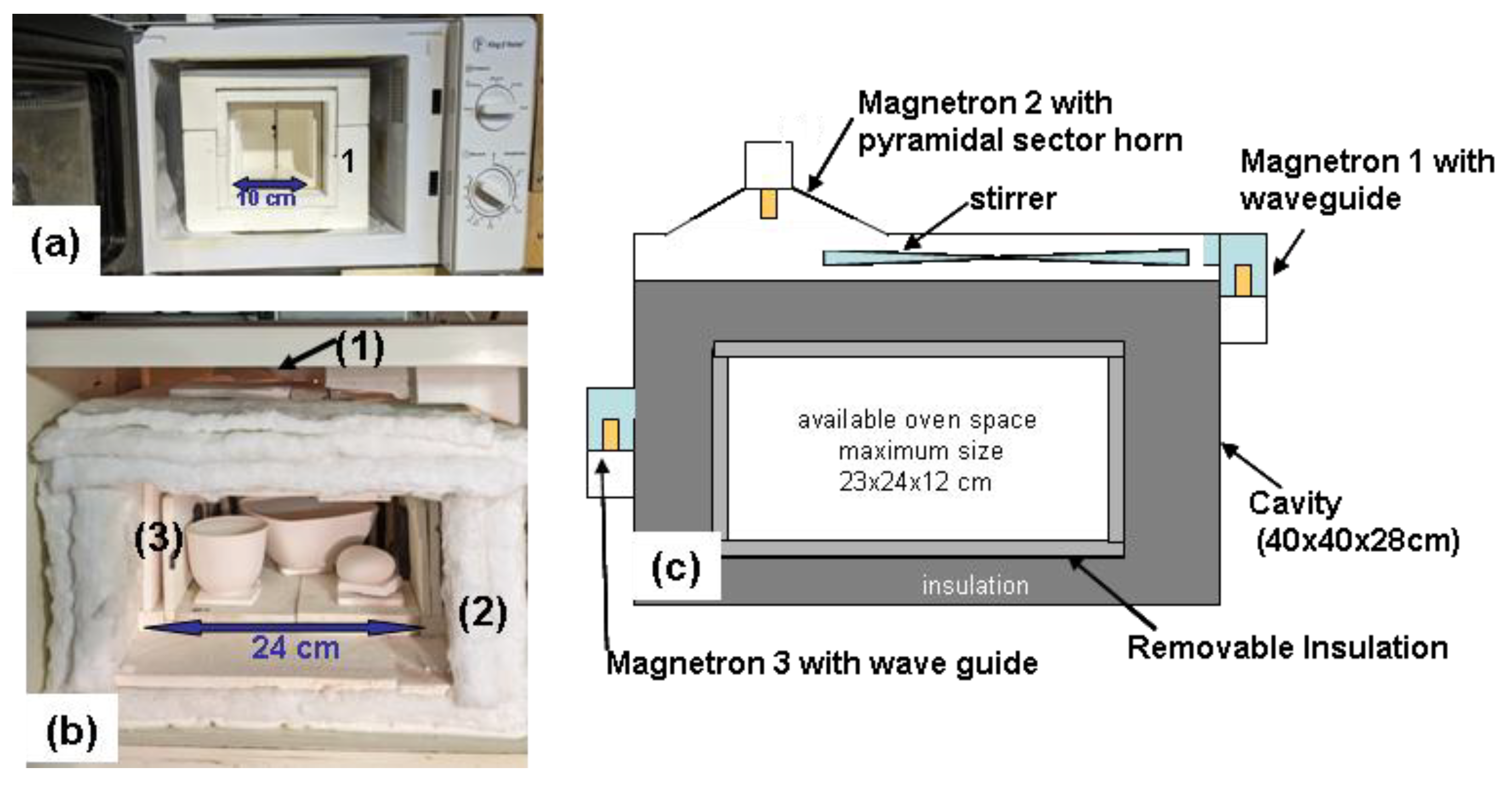
Figure 2.
SEM image of the magnetite powder used to create the susceptors. The image also reveals that some grains are agglomerated, as seen in the bottom right, which necessitates light grinding.
Figure 2.
SEM image of the magnetite powder used to create the susceptors. The image also reveals that some grains are agglomerated, as seen in the bottom right, which necessitates light grinding.
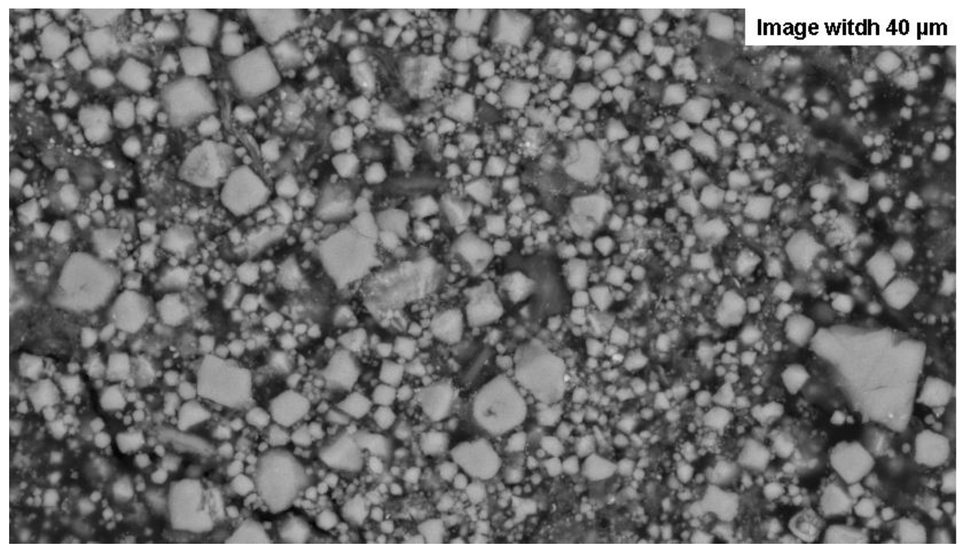
Figure 3.
Illustration of the steps of moulding and sintering powders to manufacture susceptors of various shapes. (a) Silicone moulds, 5 cm and 4 cm long. (b) Batch of 5-7 cm long susceptors, moulded and dried before sintering. (c) and (d) Batch of five susceptors undergoing sintering, viewed through the shutter of the small microwave oven door. (e) A mould milled into a refractory brick. (f) sintering inside a small 100 cm³ furnace built within the 800 cm³ furnace of the small microwave oven with a thermocouple positioned 0,6cm above the surface of the susceptor. (g) Susceptor after sintering (the base is cut for analysis). (h) 10x10 cm “snake” mould milled into a refractory brick, (i) with the powder mixture, (j) just after sintering, the blackish area at the two ends of the mould resulted from a heterogeneous powder mixture.
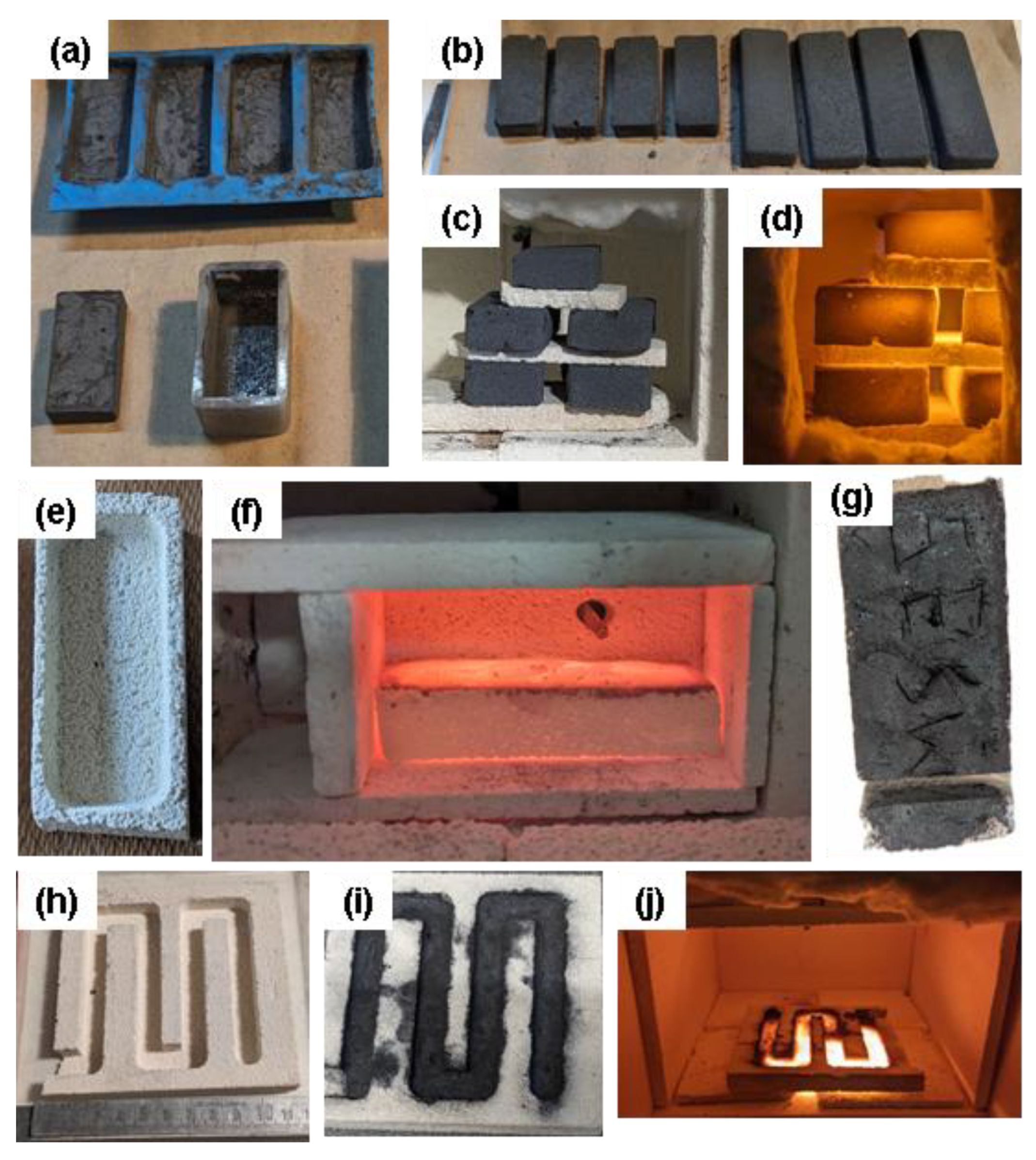
Figure 4.
Typical Firing Cycles in the Large Microwave Kiln. The kiln’s volume was 4.8 litres. The temperature was measured by a type K thermocouple placed at the top side of the kiln. (a): Firing of 320g of biscuit earthenware to 1005 °C. (b) : Firing of 310g of glazed porcelain to 1210 °C (Figure 1 (e)).
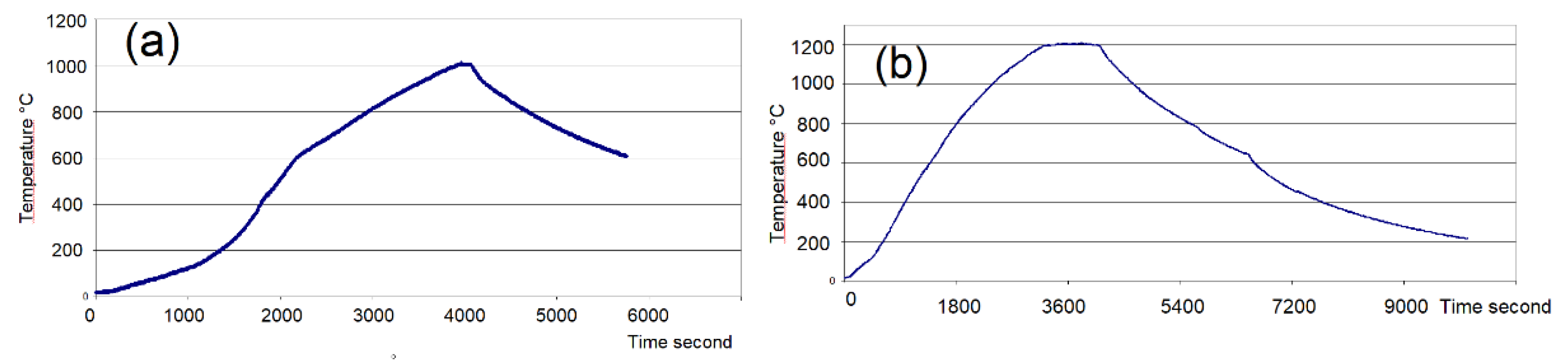
Figure 5.
Images of the first sintering runs performed to identify the best susceptor formulations. Susceptors measuring 3.5 x 2 x 1 cm were systematically placed in the same upright position inside the small microwave kiln, facing the door shutter. The sintering time was 10 minutes except for MS-3.5-22% MESH 1000 where it is 20 minutes. Temperature is measured with an optical pyrometer through the shutter. The samples placed in the same column came from the same 7cm casting cut in two halves and sintered independently to test the reproducibility.

Figure 6.
Average Heating Curves for Susceptors. This diagram shows the average heating curves over 420 seconds of the small, 100 cm3 oven (Figure 4 (f)) by the main susceptors batches. The nomenclature corresponds to that in Table 1 and Table 3.
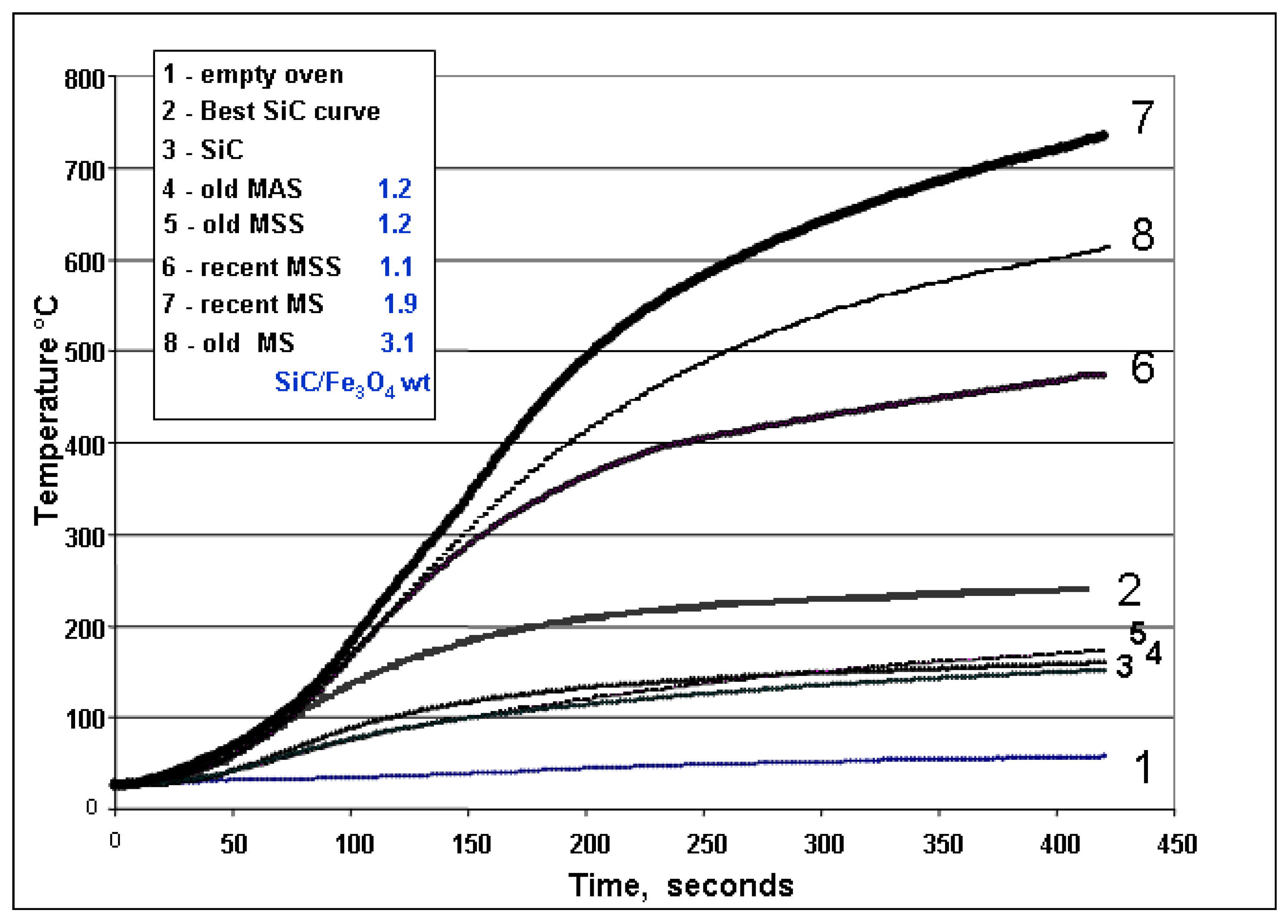
Figure 7.
Plot of the absorption power as a function of cumulated firing time. Average absorption power (W/gram) is found to decrease over time for the three main types of susceptor batches.
Figure 7.
Plot of the absorption power as a function of cumulated firing time. Average absorption power (W/gram) is found to decrease over time for the three main types of susceptor batches.
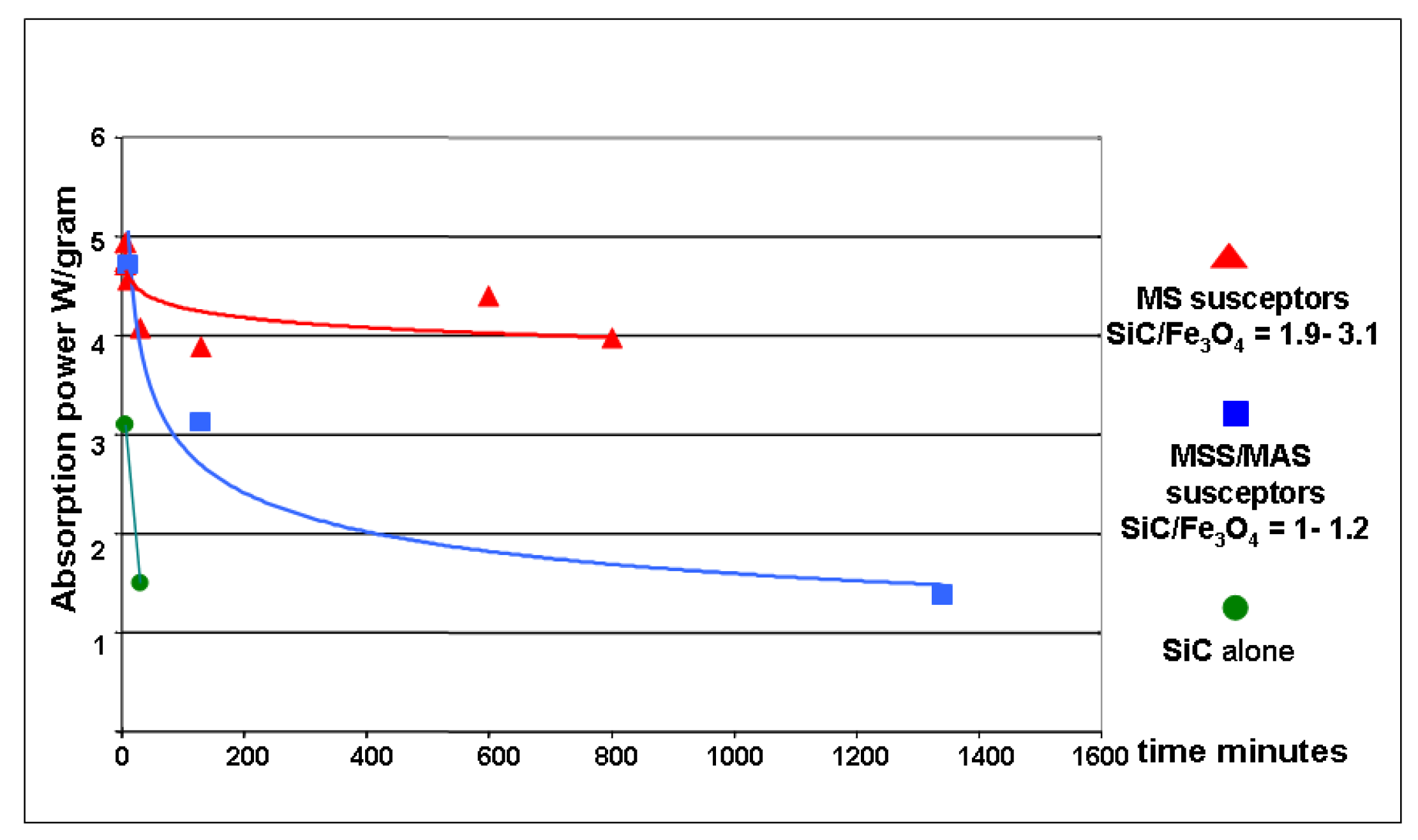
Figure 8.
Physical changes in various susceptors over time. (a) MS -25 low iron type susceptor after 10 hours of cumulative heating in firings between 1000 °C and 1300 °C. (b) U-shaped MSS -30 susceptor cut from the “snake-shaped” susceptor (Figure 4 (i), (j)), after 15 hours of cumulative heating of earthenware at 1050-1070 °C, showing traces of melting structures. (c) MSS7-30 high iron type susceptor, after 20 hours of earthenware and porcelain firings between 1000 °C and 1270 °C showing melting bubbles on its surface. (d) MSS-30 and (e) MAS-30 susceptors used under the same conditions as susceptor (c), but with an additional 75-minutes porcelain firing up to 1300 °C showing a molten film on the MAS susceptor surface while the MSS shows the same melting bubbles as before this additional firing.
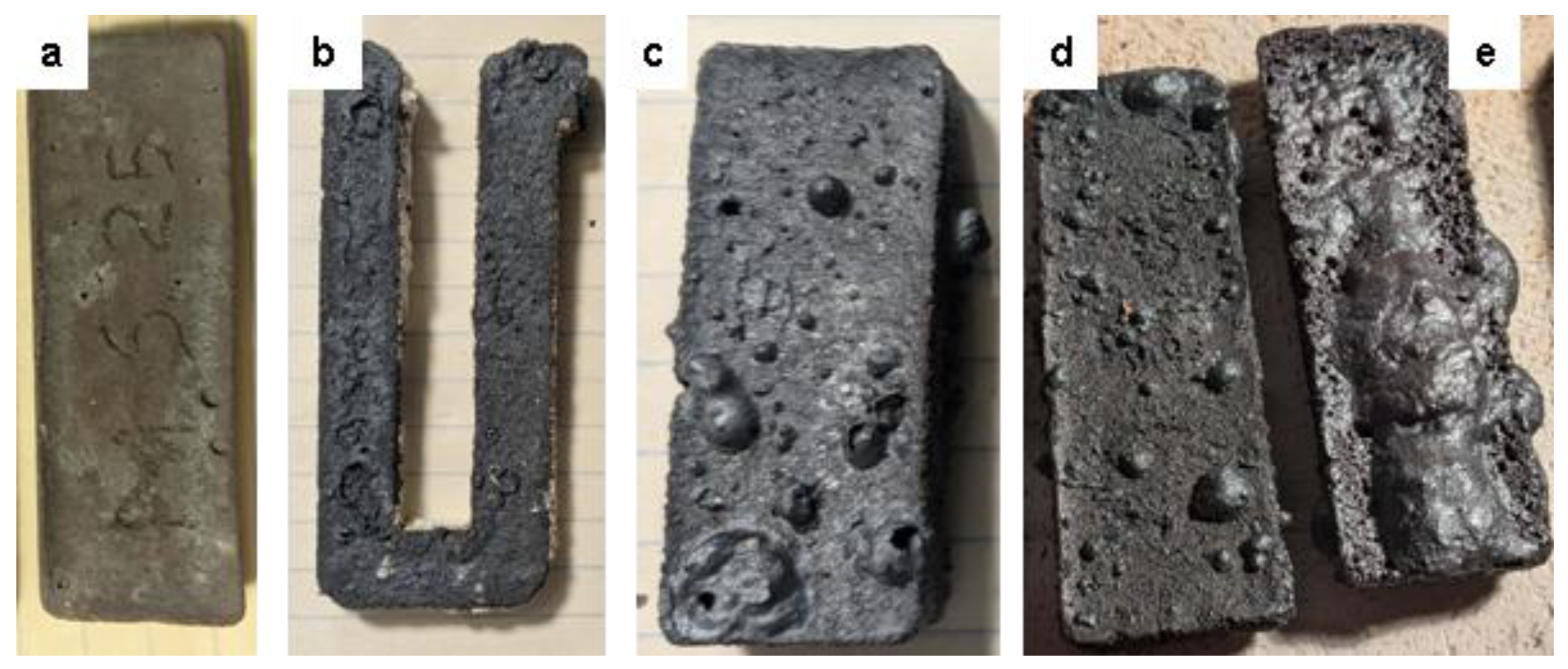
Figure 9.
Apparent Temperature Homogeneity of Susceptors as view in a heating test of 10 recent magnetite-based susceptors after 11 minutes of firing. The total weight of these 10 susceptors is 185g. The temperature of the oven, measured by a thermocouple visible at the top centre, was 810 °C just before the aperture was opened. The temperature of the susceptor surface at the time the photograph was taken was 750 °C, measured using an optical pyrometer.
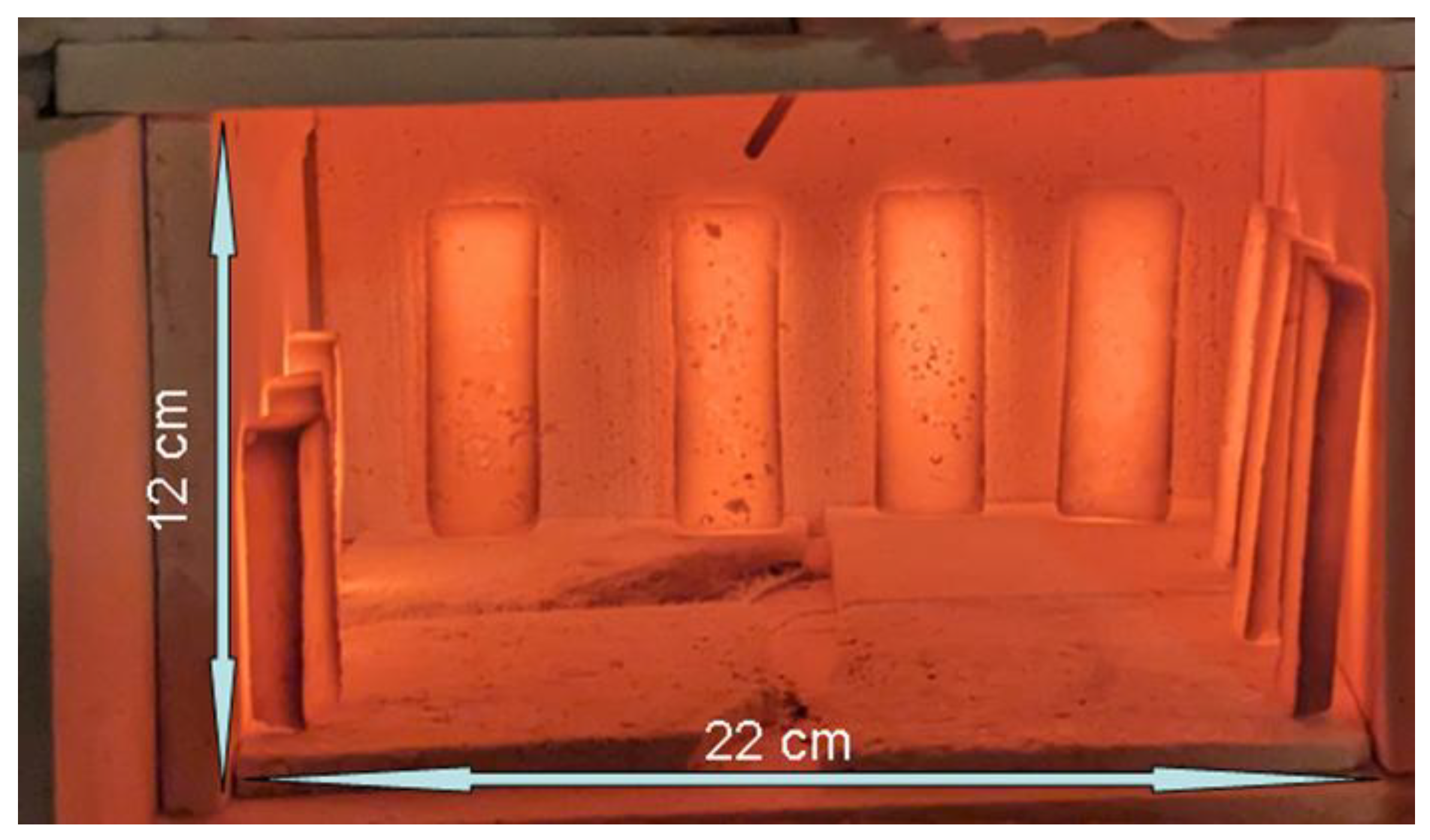
Figure 10.
SEM image of a MS-25 type susceptor after 7 minutes of sintering at 850 °C. It reveals a matrix of silicon carbide grains, coated with fine ferrosilicon particles and an overlying layer of cristobalite. Localised precipitation of hematite and dispersed iron droplets are observable within the porous regions.
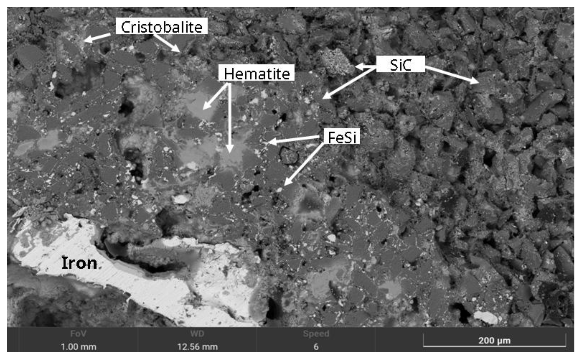
Figure 11.
SEM images and EBSD/EDS analyses of the MS-25 susceptor shown in Figure 10, following an additional 18-minute heating up to 1100 °C. (a) Overall view, displaying two distinct droplets of BCC iron (image width : 970µm). (b) EDS spectrum of the BCC iron, revealing trace contaminants of Mn and Cr, attributed to SiC grinding. (c) Detailed view of an iron droplet, where variations in brightness correspond to two distinct crystal orientations. (d), (e) EBSD analysis confirming the two different crystal orientations of BCC crystals. (f) Detailed view (BSE-Si-Fe-O-C composite image) of the matrix (image width : 50 µm) with Cris : cristobalite, F fayalite.
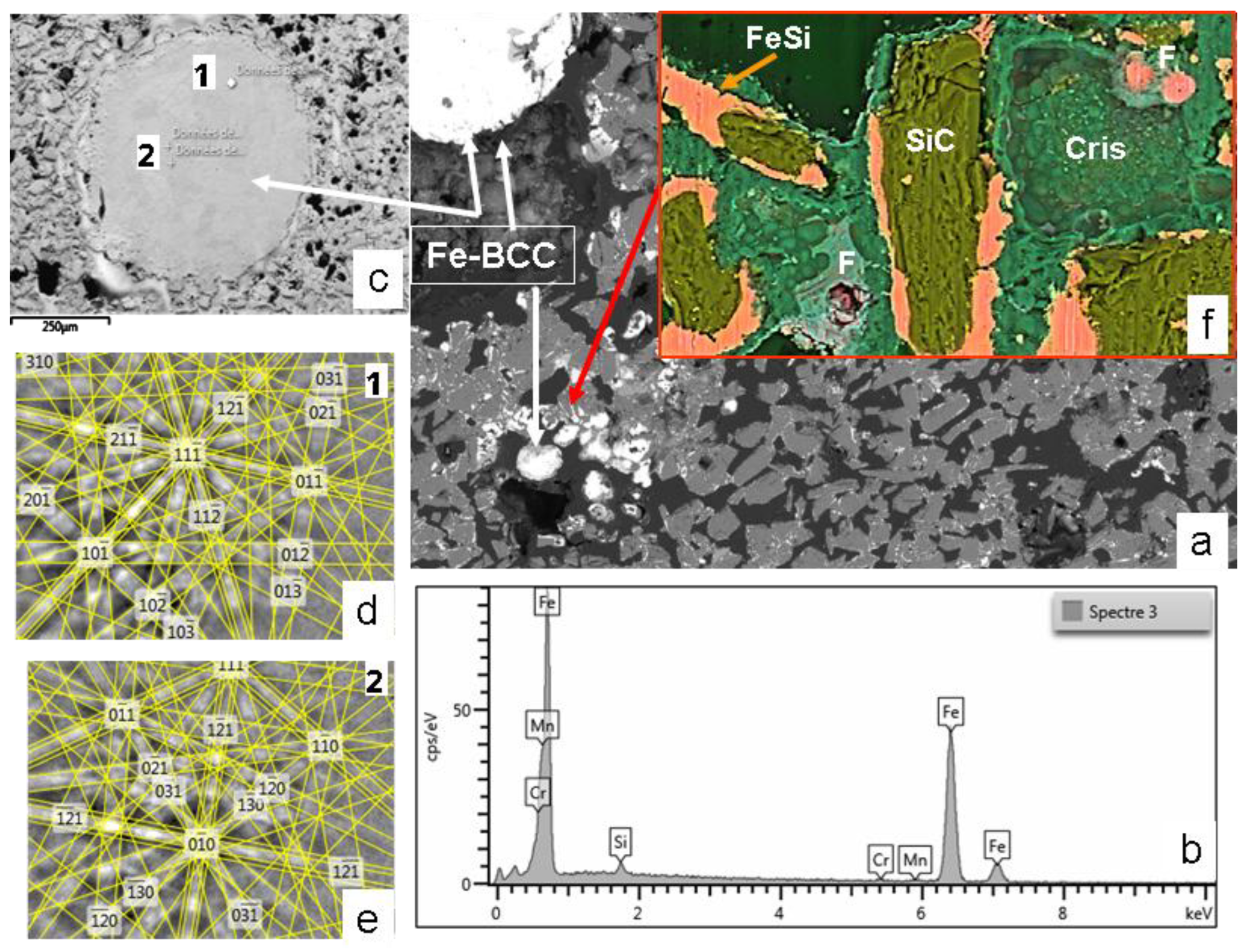
Figure 12.
This figure presents a second SEM image of the MS-25 susceptor referenced in Figure 11 complemented by chemical and crystallographic characterisation of minerals in the matrix. (a) BSE-EDS-Si-Fe-O-C composite image (100 µm wide) details the cementation of silicon carbide (SiC) and Ferrosilicon (FeSi) grains. The cement consists of cristobalite (Cris) intergrown with Fayalite (Fa) and associated with magnetite (Ma). (b) and (c) show the EBSD crystallographic determination and EDS chemical analysis for magnetite. (d) and (e) provide similar EBSD and EDS analyses for fayalite.
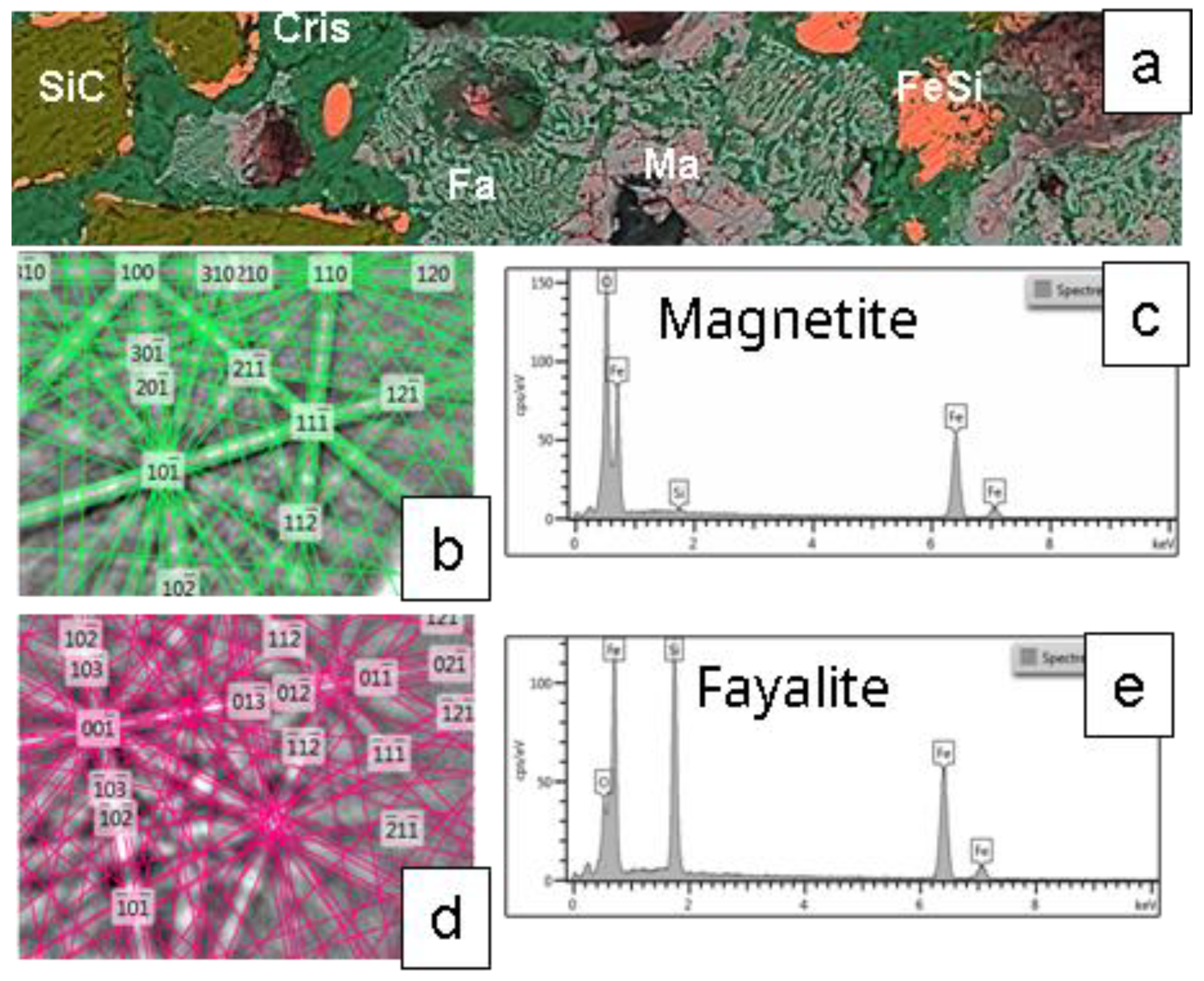
Figure 13.
Microstructural and crystallographic analysis of the MS-25 shown in Figure 11 and Figure 12. (a) BSE image (plane view) illustrating the general morphological features. (b) BSE image acquired at a 70° tilt for EBSD analysis. (c) EBSD scanning map, accompanied by a table detailing the mineralogical proportions derived from the EBSD analysis (average from two different mapping). (d), (e) EDS chemical analyses and EBSD crystallographic determination of cristobalite. (f), (g) Similar EDS and EBSD analyses for moissanite 3C. (h), (i) Corresponding EDS and EBSD analyses for ferroan forsterite (fayalite substituted to a small extent by forsterite).
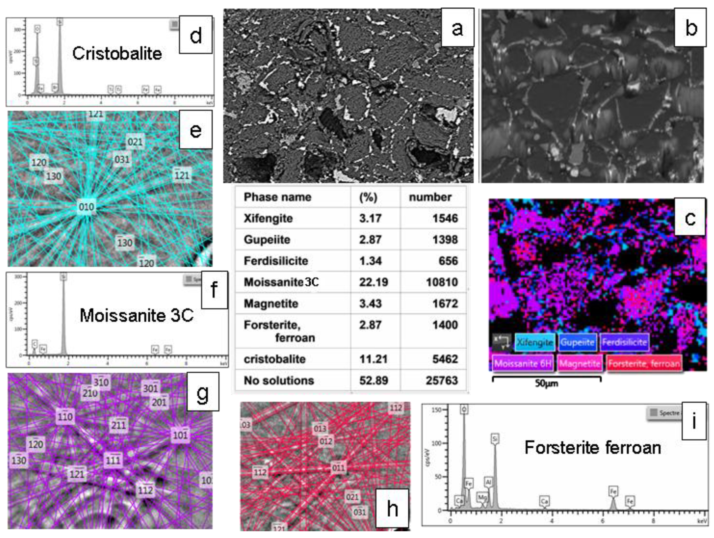
Figure 14.
Micro-structural and Crystallographic Analysis of Ferrosilicon monocrystal in MS-25 Susceptor shown in Figure 11, Figure 12 and Figure 13. (a) BSE image (70° tilted sample), illustrating morphological features, (b) EBSD scanning map (c) Ferrosilicon mineralogical proportion derived from EBSD analysis, (d), (e), (f) EDS analyses and (g), (h), (i) EBSD crystallographic characterisation of three different ferrosilicon varieties identified within the susceptor matrix.
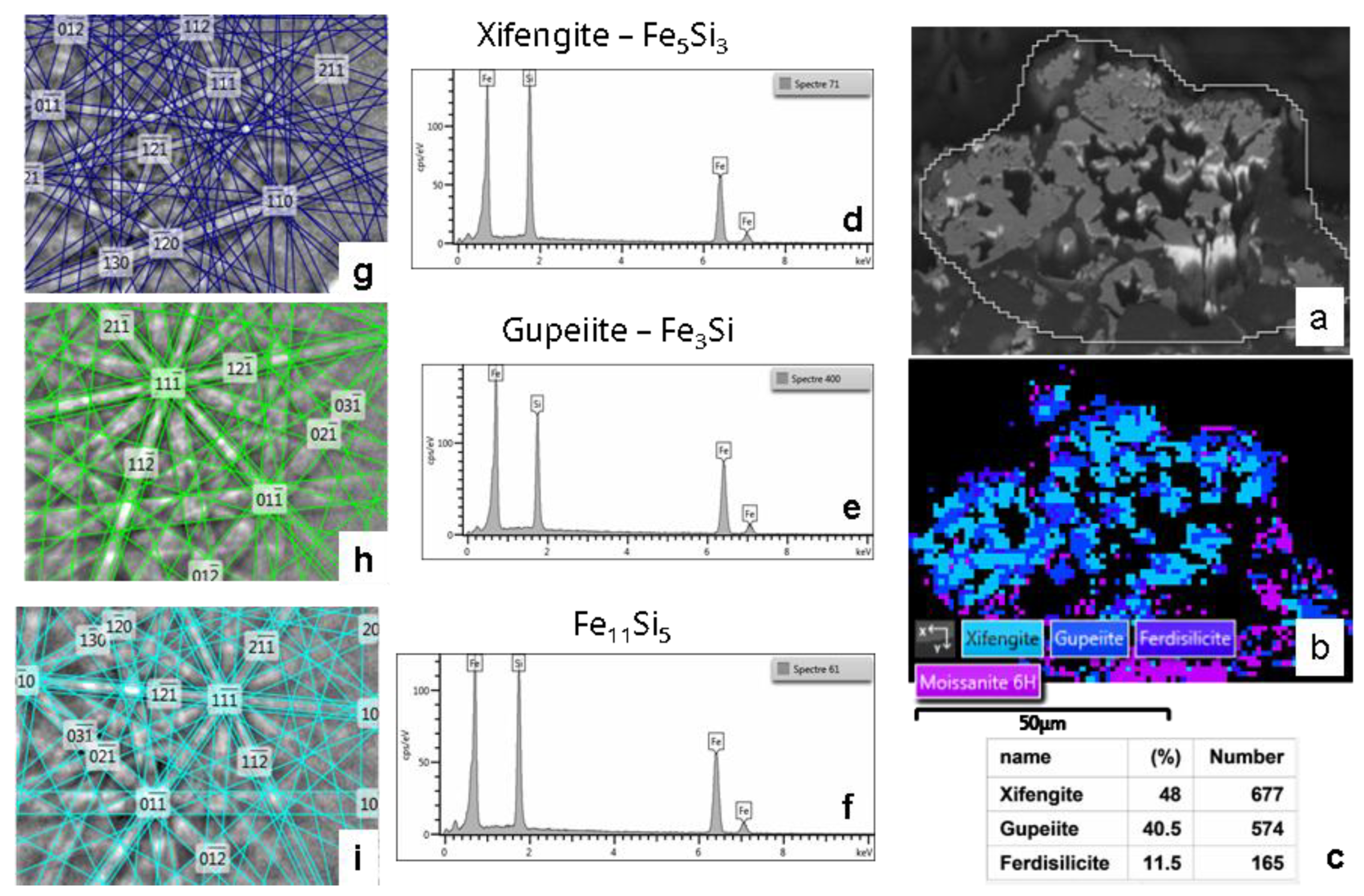
Figure 15.
SEM and EBSD analysis of a aged MAS22 susceptor with low Fe₃O₄ content, after more than 10 ceramic heating cycles up to 1300 °C. (a) Composite BSE-EDS-Si-Al-Fe-O image showing fayalite or ferrous forsterite (Fa), Fe-Si-O glass (Fa-G), and cristobalite (Cris). (b) EBSD map. (c) Table summarises the quantitative phase proportions derived from the EBSD analysis.
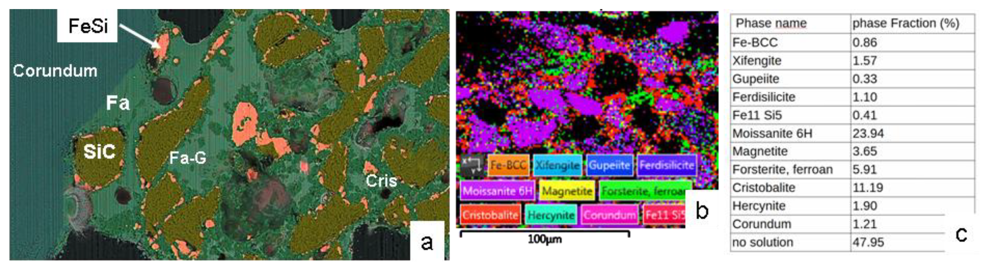
Figure 16.
SEM Image of a Recent MSS-35 susceptor cross-section. Cristobalite (Cri), Magnetite (mag), hematite-cristobalite intergrown (H+Cri).
Figure 16.
SEM Image of a Recent MSS-35 susceptor cross-section. Cristobalite (Cri), Magnetite (mag), hematite-cristobalite intergrown (H+Cri).
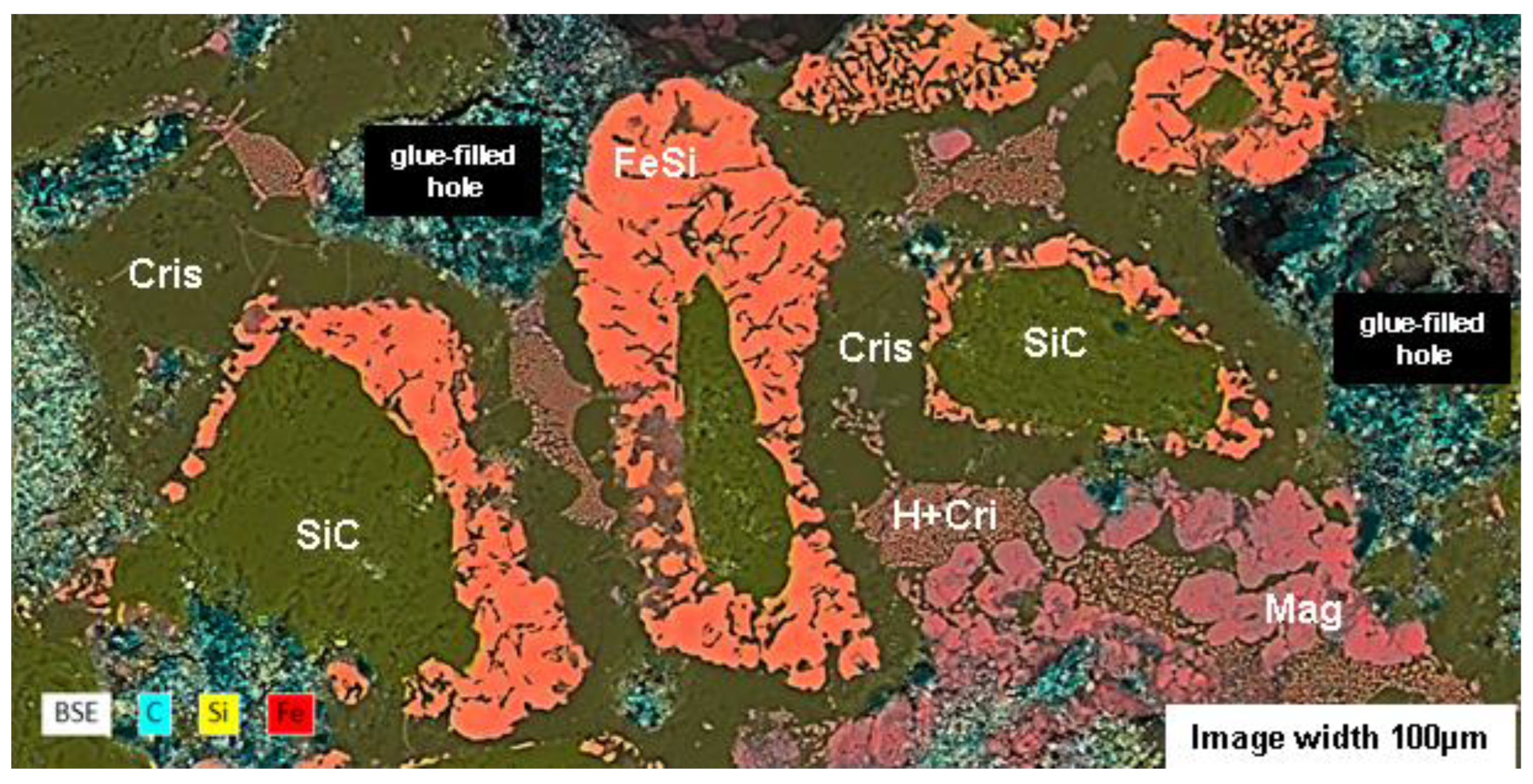
Figure 17.
SEM images of the surface features—bubble-like exudates on MSS susceptors and molten deposits on MAS susceptors (see Figure 8 d, e). (a) BSE image and (b) BSE-EDS composite Si-Fe-O image of the molten deposit on the MAS susceptor. (c) SE image and (d) BSE-EDS composite Si-Fe-O image of a bubble on the MSS susceptor. Magnetite (Mag) is reported when the shape of the mineral is recognisable among Fe₃O₄ in the BSE (a) and SE (c) images.
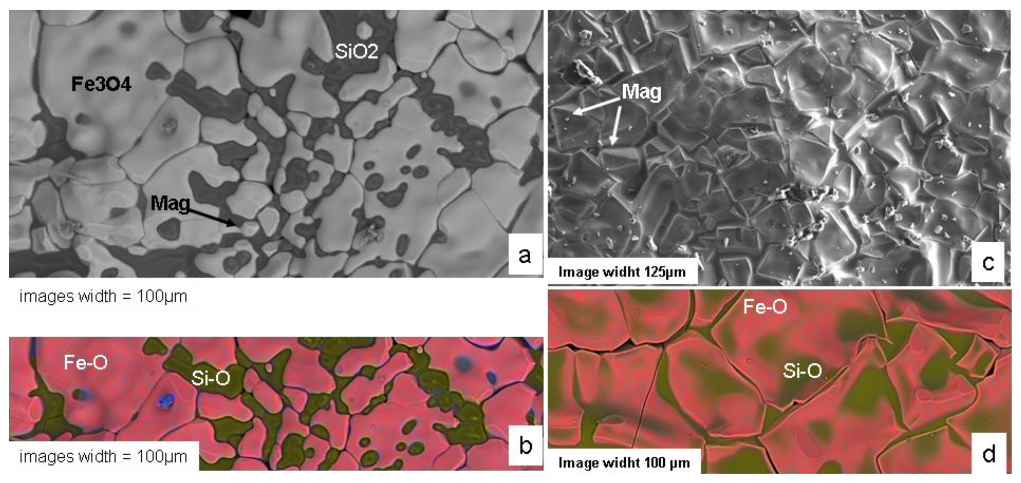
Figure 18.
(a) Image showing the flame produced by the combustion phenomenon that occurs during the initial minutes of a Fe₃O₄−SiC susceptor (7x2x0.8 cm in size) sintering process . (b) Image of the solid material formed by exposing submicroscopic magnetite powder inside a sealed silica tube showing the red crown structure around a black core (see text). The scale reference square on the paper measures 5mm.
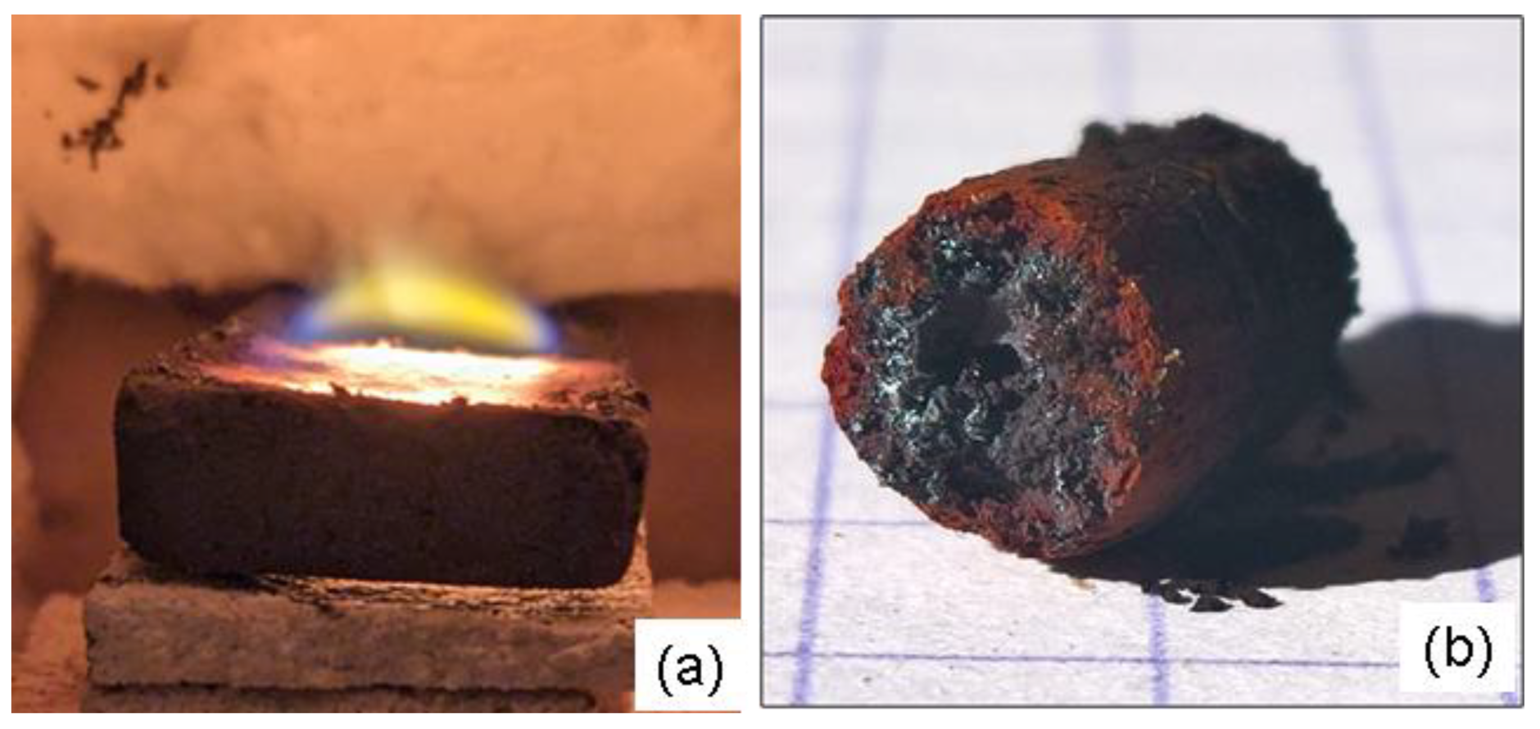
Figure 19.
Fe-Si phases diagramme adapted from (41) illustrating the stability domains of identified ferrosilicon (Gupeiite, Xifengite, Ferdisilicite and Fe11Si5). R1 dotted line indicates the composition of the reaction (R1) products (see text).
Figure 19.
Fe-Si phases diagramme adapted from (41) illustrating the stability domains of identified ferrosilicon (Gupeiite, Xifengite, Ferdisilicite and Fe11Si5). R1 dotted line indicates the composition of the reaction (R1) products (see text).
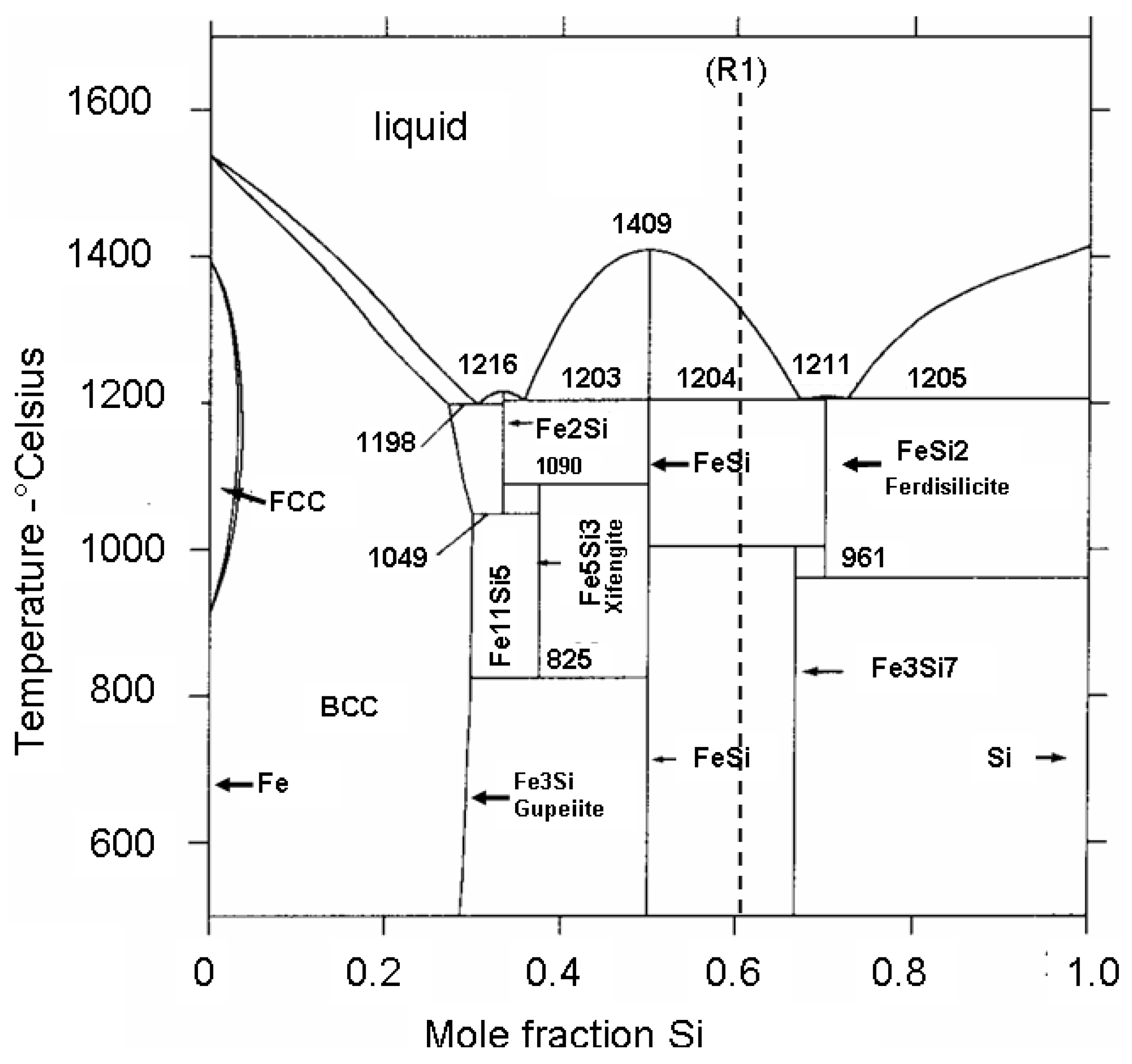
Figure 20.
Simplified phase relation of the FeO- SiO2 system in equilibrium with metallic Fe calculated using FactSage [45]. Liq = liquide, Slag = Fe-Si-O melting phase. Arrows indicate the SiO2 fraction in the susceptor in function of their global composition with the corresponding melting proportions.
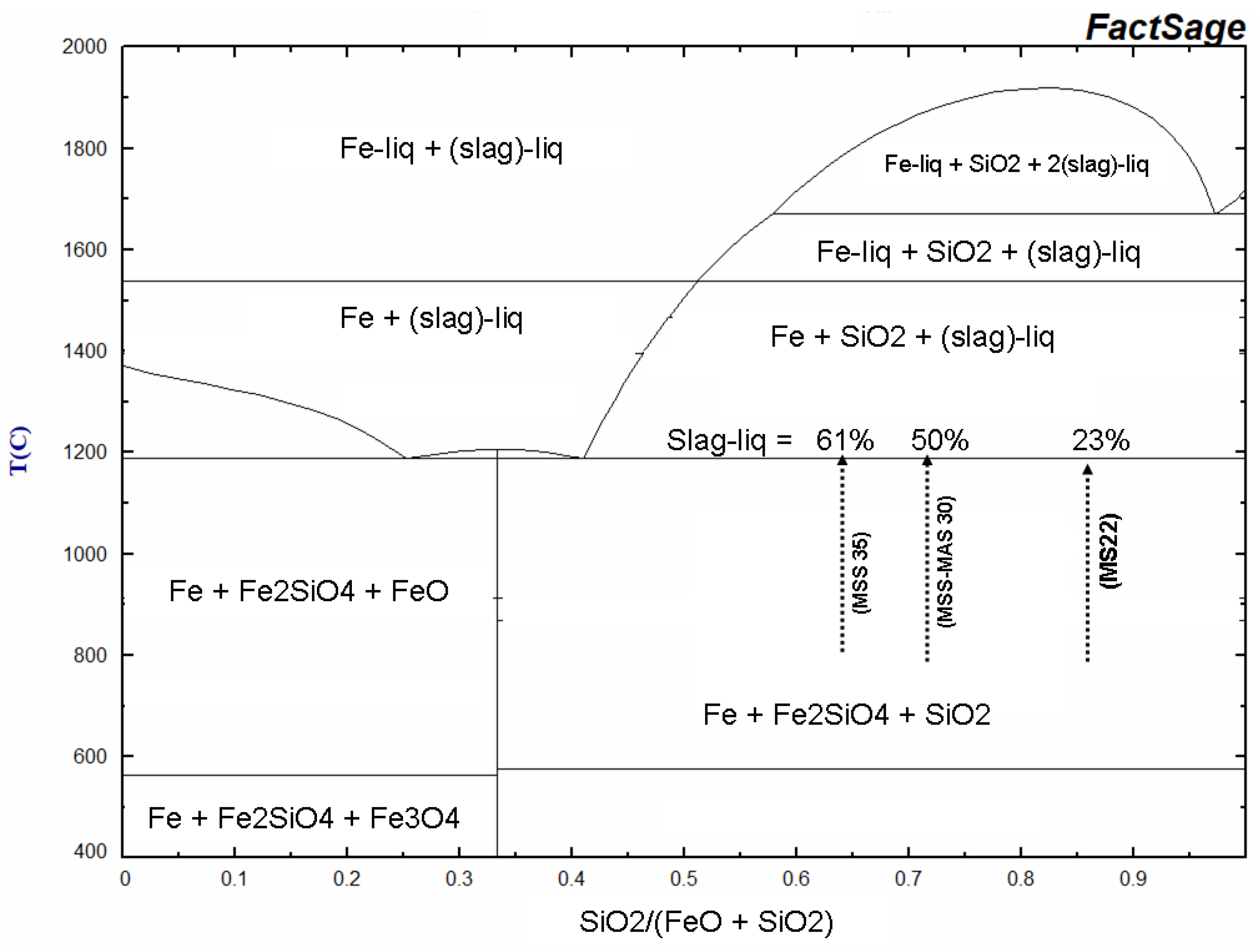
Figure 21.
This diagram compares the heating rate curves of the susceptor with those of the kiln for two similar porcelain firing to 1280 °C in the small microwave kiln. The measurements were taken separately during the two successive firings of identical porcelain pieces in the same kiln configuration (80g of porcelain, 80g of MS-25 susceptors).
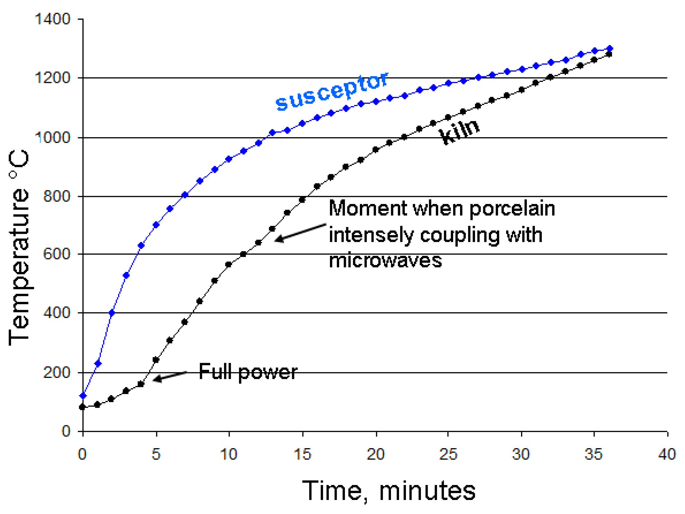
Figure 22.
Melting of JM23 Brick upon Contact with an Iron-Rich Susceptor during Porcelain Firing at 1300 °C. The silica-mullite that makes up the JM23 brick melts on contact with susceptors glasses (T°> Fe-Si-Al-O eutectic in reducing conditions). Despite this, the porcelain piece remained intact and was well-fired. The porcelain tealight holder is a handcrafted creation by Caroline Combes.
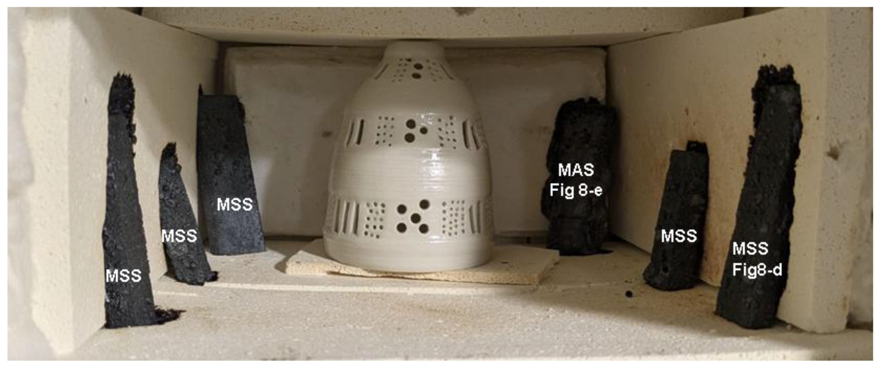
Figure 23.
Examples of Large Earthenware Pieces Successfully Fired and Glazed in a Microwave Kiln. (a): 435g pyramidal tealight holder(18x16x12 cm) in its raw state, positioned in the kiln. Six susceptors (130g), some still in their refractory mould, are arranged around the piece. (b): The same tealight hageder after a 90-minute firing at 1030 °C and a subsequent 70-minute glazing at 1030 °C. (c): A decorative set of two earthenware pieces fired and glazed separately. The base (21x16x6 cm, 765g) was fired with six susceptors (142g) in 104 minutes at 1026 °C and glazed in 73 minutes at 978 °C. The tower (17x7x5 cm, 200g) was fired with other pieces in 90 minutes at 995 °C and glazed in 67 minutes at 1020 °C. (d): Water butter dish: A 170g water butter dish (8x10 cm) fired in the same batch as the tower, in the presence of seven susceptors (160g). The water butter dish is a handcrafted creation by ceramist Caroline Combes.
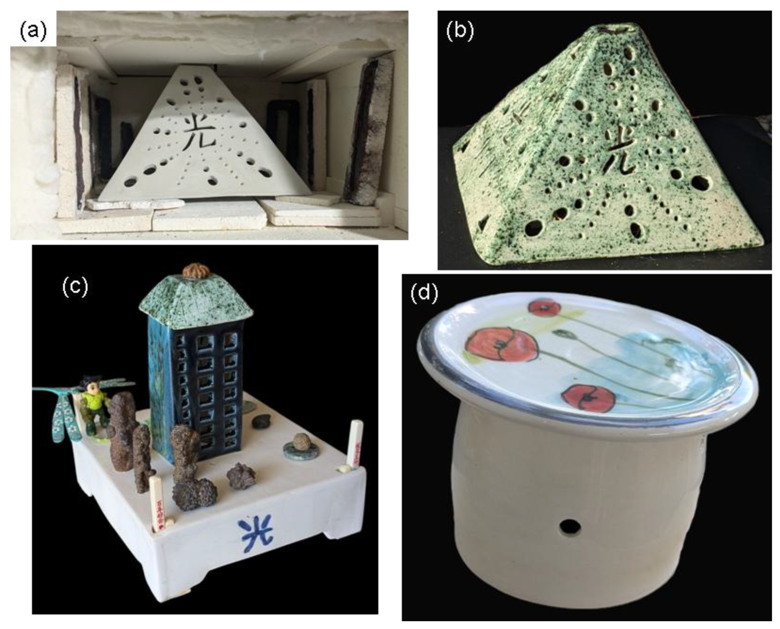
Figure 24.
X-ray diffractograms of fired earthenware and porcelain. (a) porcelain fired to 1280 °C, heating time 48mn. (b) biscuit earthenware fired to 1005 °C, heating time 66 mn. Quantitative analysis was performed using the Rietveld refinement method, and only phases present at a concentration of more 2% are listed.
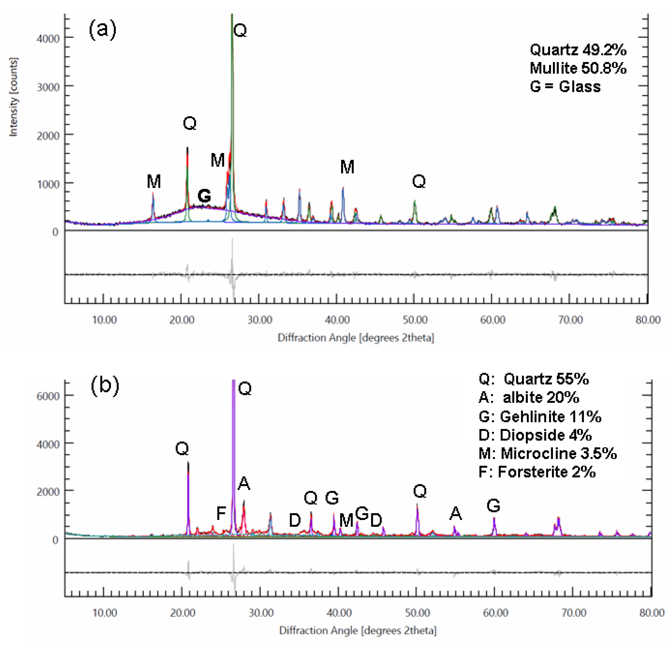
Figure 25.
Comparative photographic analysis of commercial earthenware glazes fired at different temperature in the microwave kiln. The glazes were designed for a temperature range between 1020–1060 °C (crystal turquoise and coral red) and 1020–1100 °C (panzy). Five firings, using six susceptors, of the three glaze batches were conducted on test pieces made from three types of commercial white earthenware clay. Each firing lasted between 30 and 50 minutes, depending on the target temperature, with a 10-minute plateau at the maximum temperature. The temperature was measured using a thermocouple placed in the middle of the oven, 4 cm above the pieces. The three 1050 °C glazes of coral red are on three different white commercial earthenware pastes (FDS, Loza and a common one).
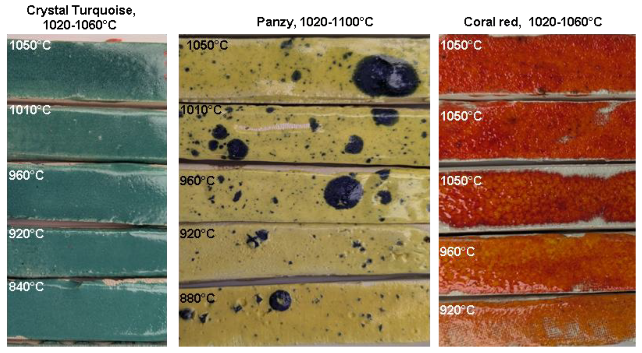
Figure 26.
Representative firing cycles in the large microwave kiln for porcelain and earthenware in different volume (V) configurations. (a) porcelain degourdi shown in Figure 1e and (b) glazing earthenware shown in Figure 23b. (c) and (d) porcelain sintering and glazing. The data is represented by three curves for each firing: The blue curve shows the temperature measured by a thermocouple. The pink curve represents the instantaneous power, manually adjusted for each microwave. The green curve shows the cumulative electrical consumption, including both the microwaves and the ventilation which works also during cooling.
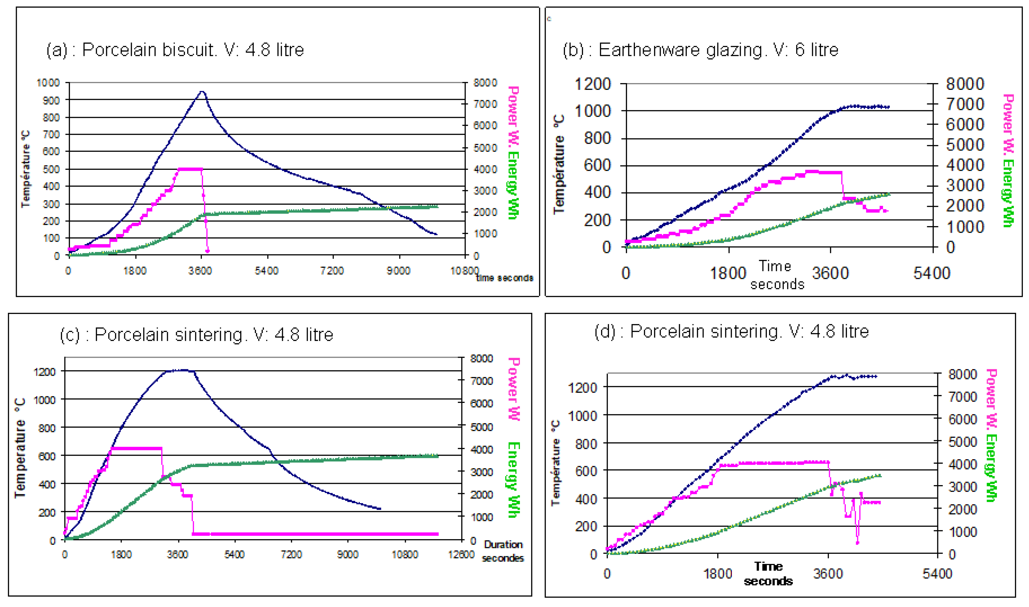

Table 1.
main types of susceptors manufactured. * only SiC is considered to calculate the Si mole fraction, the porosity is calculated as the difference between the volume of the susceptor and that of the mineral constituents.
Table 1.
main types of susceptors manufactured. * only SiC is considered to calculate the Si mole fraction, the porosity is calculated as the difference between the volume of the susceptor and that of the mineral constituents.
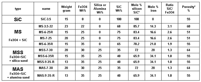
Table 2.
specific heat value for the considered minerals and calculation of adsorption power.
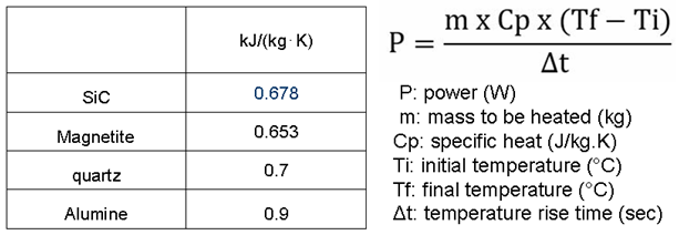
Table 3.
Average Absorption Power (W/gram) for the main batches of susceptors. The values are presented as a function of their cumulative usage time, from their initial sintering up to their final state after firing ceramics. Cumulative usage time is defined as the total heating time, not including cooling periods.
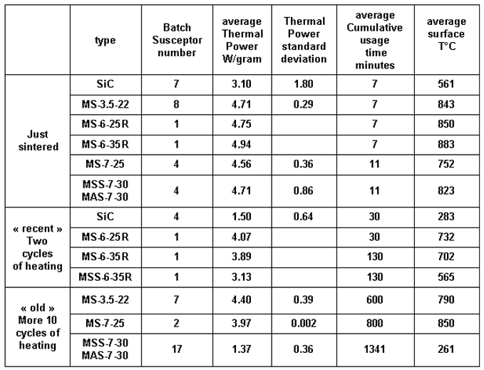
Table 4.
Mineralogical transformations of the main types of susceptors, from their sintering process to their transformation during prolonged use in ceramic heating cycles. The data are derived from the compilation of observations and analyses performed using SEM techniques: SE, BSE, EDS and EBSD imaging and characterisations, as well as powder X-ray diffraction. The symbols (+) and (-) correspond to the apparition or disappearance of a phase. The number of symbols in brackets represents an approximate intensity between 0 and 5 (100%). *(1) and *(2) indicate that the phase is primary (initial) or secondary (subsequent).
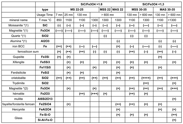
Table 5.
partial quantification of the mineralogical and porosity changes resulting from thermal cycling, comparing a just sintered susceptor (MS22 at 1100∘C, Figure 11) with an aged one (MAS22 reaching 1300 °C, Figure 15).
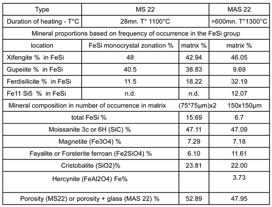
Table 6.
Stoichiometric balance following reactions R1 and R2 of the susceptor sintering reactions and its consequences on solid phase volume reduction and gas emissions as a function of material composition. (a) and (b) Calculation of the total amount of gas generated by a 150-gram susceptors assembly in the same furnace over their typical lifespan of approximately ten heating cycles in the furnace.
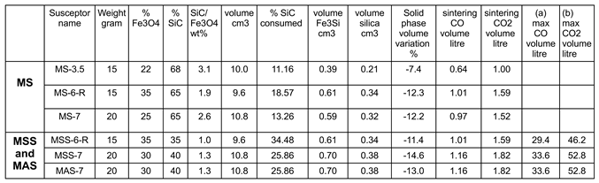
Disclaimer/Publisher’s Note: The statements, opinions and data contained in all publications are solely those of the individual author(s) and contributor(s) and not of MDPI and/or the editor(s). MDPI and/or the editor(s) disclaim responsibility for any injury to people or property resulting from any ideas, methods, instructions or products referred to in the content. |
© 2025 by the authors. Licensee MDPI, Basel, Switzerland. This article is an open access article distributed under the terms and conditions of the Creative Commons Attribution (CC BY) license (http://creativecommons.org/licenses/by/4.0/).
Copyright: This open access article is published under a Creative Commons CC BY 4.0 license, which permit the free download, distribution, and reuse, provided that the author and preprint are cited in any reuse.


