
Submitted:
21 October 2025
Posted:
21 October 2025
You are already at the latest version
Abstract
The rapid accumulation of space debris presents a serious threat to operational spacecraft, with the capture and removal of rapidly tumbling non-cooperative targets being a primary challenge. Non-contact electromagnetic de-tumbling technology is a promising solution due to its enhanced safety. This paper addresses the issue of torque modeling and validation in the electromagnetic de-tumbling process for a specific configuration involving a magnetic dipole and a spherical shell under a symmetrically distributed magnetic field. Based on the principles of electromagnetic induction, an approximate analytical expression for the electromagnetic eddy current torque on a rotating spherical shell within a dipole magnetic field is first derived. A high-fidelity finite element model is then established, which reveals a systematic discrepancy between the initial theoretical model and numerical simulation results. A distance-dependent power-law correction factor is introduced to calibrate the theoretical model, significantly improving its accuracy and reducing the average error to 1.5 percent. Finally, a ground-based experimental platform is designed and implemented. Experimental results demonstrate that the corrected approximate analytical model agrees well with the empirical data, verifying its validity and accuracy under the given conditions and providing a reliable theoretical basis for the design of future space debris de-tumbling controllers.
Keywords:
electromagnetic de-tumbling
; approximate analytical formulation
; space debris
; finite element simulation
; experimental validation
1. Introduction
The orbital environment has seen a rapid proliferation of artificial objects since the beginning of the space age in 1957[1].The current catalog includes over 54,000 tracked objects exceeding 10 cm in size, with only around 17% remaining functional satellites[2].The remaining objects are classified as space debris, comprising non-functional satellites, expended rocket stages, and fragmentation debris. Active debris removal (ADR) plays a vital role in mitigating orbital debris accumulation and tackling the escalating space debris problem[3].Current research has investigated various ADR approaches, such as robotic arms[4], net[5], tentacle [6], the tether-gripper mechanism [7], and harpoon[8].
The superposition of residual angular momentum, solar radiation pressure, and gravitational gradient torques induces complex tumbling dynamics in space debris.Observations indicate that certain space debris can attain angular velocities exceeding several hundred degrees per second while exhibiting continuous rotational axis precession. Such hyper-rotational states constitute unstable, high-energy configurations that significantly elevate fragmentation risks. The direct capture of rapidly rotating, large-scale debris poses substantial hazards, including potential catastrophic collisions and complete loss of spacecraft control, primarily due to the limited dynamic operational range of existing orbital robotic manipulators. Current space robotic systems demonstrate a maximum capture capability for targets with rotation rates below 5°/s[9] , necessitating a mandatory de-tumbling phase to stabilize the debris prior to capture operation[10,11,12,13,14].
Recent years have witnessed significant advancements in both contact and non-contact de-tumbling techniques for space debris mitigation. Contact-based approaches, such as brush-contact systems[15], mechanical pulse[16], tethered space net robots [17], and space-tug systems[18], require precise close-proximity operations that inherently increase mission complexity and collision probability. Non-contact alternatives, including plume impingement [19], laser ablation [20], and electrostatic force applications [21], offer reduced operational risks but demonstrate performance characteristics highly sensitive to target debris geometry parameters.
Non-contact de-tumbling techniques utilizing eddy currents have attracted considerable attention due to their benefits, such as clean operation, intrinsic safety, and few geometrical limitations. Sugai et al. [22] and Du et al. [23,24] introduced an approach for de-tumbling non-functional targets by employing AC electromagnetic coils as end-effectors on space robotic arms. Gómez et al. [25] and Walker et al. [26] described a technique that uses a large high-temperature superconducting (HTS) coil carried onboard a spacecraft to generate a nearly uniform magnetic field around a target. Liu et al. [27] and Meng et al. [28] suggested a method that uses rotating permanent magnets to produce a traveling magnetic field in the target’s vicinity, thereby increasing the de-tumbling torque.
The precise modeling of electromagnetic forces and torques is fundamental to analyzing the dynamics of the de-tumbling process and to developing effective control strategies for de-tumbling. Analytical expressions for calculating eddy current torque were provided by Smith, et al.[29] and Ormsby, et al.[30], who derived them by simplifying structures such as a cylindrical shell, a conical shell, and a spherical shell in a uniform magnetic field.
Analytical expressions for eddy current torque or force are available only for a restricted set of configurations, making numerical methods essential in the majority of practical scenarios. Praly, et al. [31] developed a comprehensive framework for modeling induction effects, which predicts an exponential decay in the spin rate of conductive space debris. The study by Gómez, et al.[25] introduces an approach for evaluating eddy current torque via a Magnetic Tensor, obtainable through Finite Element Analysis. Li, et al.[32] suggested a finite element technique to determine the eddy current torque on an arbitrarily shaped rotating conductor within a magnetic field. Nurge, et al.[33] obtained asymptotic expression for the force and torque on a slowly rotating sphere subjected to an axisymmetric magnetic field. Furthermore, Yu, et al.[34] established asymptotic expression characterizing the electromagnetic interaction between two magnetic dipoles and a spherical shell in an axisymmetric field. However,the calculation of the torque exerted on the shell’s surface for a magnetic dipole interacting with a spherical shell under axisymmetric magnetic field conditions relies on numerical methods, for which no corresponding analytical approach has been developed, nor has any experimental verification been conducted.
This paper proposes and validates an approximate analytical model of magnetic dipole-spherical shell electromagnetic torque applicable to symmetric magnetic field distribution conditions. Section 2 models the electromagnetic de-tumbling system and the electromagnetic interaction between the magnetic dipole and the spherical shell. Section 3 derives an approximate analytical expression for the electromagnetic eddy current torque acting on a rotating spherical shell under symmetric magnetic field distribution. Section 4 details the finite element modeling process, where simulation analysis reveals discrepancies between the initial analytical model and numerical results, leading to the introduction of a power-law correction factor to enhance the model’s computational accuracy. Based on this, a rigid-body dynamic model of the spherical shell is further established to simulate its angular velocity decay process under the corrected electromagnetic torque. Section 5 describes the setup of the experimental platform and the experimental methods, comparing the measured results with the corrected analytical solutions. Section 6 summarizes the research work and presents conclusions.
2. The Formulation of De-Tumbling Problem
The de-tumbling system configuration,comprising a service satellite,a single space robotic arm,electromagnetic coil and a uncooperative target,is depicted in Figure 1.
Three assumptions are made here to simplify the model complexity.
- Firstly, the target is simplified as a non-magnetic conducted spherical shell;
- Secondly, the electromagnetic device is simplified to a magnetic dipole because the relative distance between the electromagnetic device and the target is much greater than the diameter of the electromagnetic device to avoid collisions;
- Finally, the magnetic moment of the electromagnetic device is perpendicular to the angular velocity of the spherical shell.
As shown in Figure 2, a Cartesian inertial coordinate system is established with origin point O and orthonormal basis vectors . Consider a spherical shell with radius R, thickness e, origin point , electrical conductivity ,and magnetic permeability . Coordinate systems and share the same origin. Assume that the spherical shell rotates with angular velocity , under the influence of a magnetic dipole with a magnetic moment , where and . The magnetic dipole is fixed at position (0,0,h) in the coordinate system O, where h is the distance from origin (0,0,0) to the dipole along the z-axis. The vector , passing though the shell’s center, represents the displacement from a magnetic dipole located at (0,0,h) to an point on the surface of spherical shell, where and .
The magnetic field generated by a magnetic dipole on a spherical shell can be described as.
When a spherical shell moves through a magnetic field generated by a dipole, eddy currents are induced in accordance with Ohm’s law, which can be expressed as.
where represents the induced electric potential. is the primary magnetic field. represents the velocity of spherical shell relative to the primary magnetic field.
The induced eddy currents satisfy the principle of charge conservation throughout the conducting volume.
The boundary condition for eddy currents is governed by their confinement within the conducting medium, which can be expressed as.
Consequently, the induced electric potential satisfies the Poisson equation.
The Lorentz force density acting on the spherical shell under an applied magnetic field can be formulated as.
The total electromagnetic force acting on the spherical shell is obtained through volume integration of the Lorentz force density distribution.
where V is the volume of spherical shell. The electromagnetic torque exerted on the spherical shell is expressed as.
3. Derivation of the Approximate Torque Analytical Expression
The focus of this study is to derive approximate analytical expressions for the coaxial configuration between a magnetic dipole and a spherical shell. To facilitate the derivation, Equation (1) is reformulated in terms of unit vector (, , ) representation.
where and .
Equation (9) can thus be simplified to the following form.
The induced magnetic moment of a conducting spherical shell immersed in an external dipole field is given by.
By combining Eq. (10) with Eq. (11),the analytical expression for the induced magnetic moment of the spherical shell in an external dipole field is obtained , as presented in Eq. (12).
Under the assumption 2, the torque acting on a rotating spherical shell in a magnetic dipole field can be calculated using Eq. (13).
By substituting Eq. (10) and Eq. (12) into Eq.(13), the approximate analytical expressions for the torque acting on a rotating spherical shell under a magnetic dipole field are obtained as follows.
4. Simulation Analysis and Parameter Calibration
A finite element model is developed to verify the correctness of the approximate analytical expression for the electromagnetic torque that has been derived. The parameters used in the simulation are provided in Table 2.
4.1. Finite Element Modeling
For achieving the goals of precisely numerical accuracy, computation speedup and good convergence behavior, it is necessary for reasonable meshing grid operations.The firstly effective approaches is mesh parameterization, where the magnetic field of the spherical shell generated by the magnetic dipole is precomputed. It can enhance the mesh geometric quality extremely and decrease computational time for avoiding the influence of meshing the point of the magnetic dipole. Then,the next effective step is to layer the grid into six layers , which are as follows: outermost atmospheric layer ,target outer atmospheric layer, magnetic dipole layer ,target layer ,target inner atmospheric layer and inner core layer as shown in the Figure 3.
To ensure rapid convergence and accuracy, the radius of the outermost atmospheric layer needs to be six times the radius of the spherical shell. And the mesh near the spherical shell is refined due to the rapid variation of the eddy currents on its surface. The specific thickness and radius of each layer are shown in Table 1. The high-quality meshes can be obtained with average mesh quality 0.9095 by sweeping each layer to generate the hexahedron mainly. By optimizing the parameter settings, the computational time is significantly reduced while maintaining the accuracy of the results.
4.2. Modification and Error Analysis of the Analytical Expression for Torque
To verify the correctness and accuracy of the derived approximate analytical expression for electromagnetic eddy current torque, finite element simulation was used to calculate the distribution and variation of current density on the spherical shell surface, as well as the torque experienced by the shell, under the symmetric magnetic field distribution of a magnetic dipole with the same magnetic moment presented in Figure 4. From the common characteristics of the spherical shell distribution, an electromagnetic eddy current loop is formed with its center at the position where the magnetic dipole moment points toward the shell. The current density distribution follows the principle of electromagnetic induction, with the eddy current path perpendicular to the magnetic field variation.
When the spherical shell is away from the magnetic dipole, the eddy current loop generated on the shell surface is the strongest, with a maximum value of and a minimum of , exhibiting the largest current density gradient in all directions. As the distance h increases (from to ), the current density significantly decreases when the shell is away from the dipole, with a maximum of and a minimum of . The rate of decrease in current density is indeed faster than the increase in distance. Specifically: the distance increases from to (approximately 1.67 times), but the maximum current density drops from about to about (a decrease of about 8 times). This indicates a strong inverse power-law relationship between current density and distance, exceeding the order of , which aligns with the general trend of the derived electromagnetic formula.
The theoretical formula for electromagnetic torque derived in this study is based on three idealized assumptions, thus inherently deviating from finite element simulation results. To enable the theoretical model to more accurately calculate electromagnetic eddy current torque at different distances, thereby laying the foundation for subsequent electromagnetic de-tumbling strategy formulation and controller design, we introduced a distance-dependent correction factor, whose expression is as follows.
where a is the amplitude coefficient, compensating for the overall amplitude deviation of the theoretical model;b is the distance exponent, capturing the nonlinear variation characteristics of torque with distance.
This form has clear physical significance, with the term reflecting the influence of magnetic field attenuation. Parameters a and b can be determined by fitting finite element data. Compared to complex physical models, the power-law form is computationally simple and efficient. The correction factor parameters are determined by minimizing the error between theoretical predictions and finite element data. The 11 sets of finite element data were collected within a typical distance range which is h ranges from to with an interval of .The established error function is shown below.
where is the electromagnetic torque value obtained from finite element simulation, and is the theoretical derivation value, which is the same as .
The parameters were optimized using the Levenberg-Marquardt algorithm, resulting in a final fitting quality of = and an average error = . The optimized parameter values are and .
This indicates that the correction factor effectively corrects the deviation of the theoretical formula .
Therefore, the expression for the electromagnetic eddy current torque corrected by the correction factor is as follows.
Figure 5 shows a comparison diagram of the analytical expression of electromagnetic eddy current torque before and after correction, as well as a comparison diagram between the finite element simulation value and the corrected approximate analytical solution of electromagnetic eddy current torque.
As shown in Figure 6, the average error of is only 1.5%, and within the entire test distance range ( to , in increments), the maximum error is consistently controlled within 3%. Such minor fluctuations are acceptable, indicating that there are higher-order terms between the theoretical model and the finite element simulation, which more closely approximates the real physical environment. These terms are excluded without affecting computational accuracy and speed.
4.3. Dynamics of Electromagnetic De-Tumbling
The variation of the angular velocity of a non-cooperative target rotating in a magnetic dipole field is investigated under the following assumptions. All components of the electromagnetic de-tumbling system are modeled as rigid bodies. The electromagnetic device (e.g., an electromagnetic coil), which is mounted at the end of a space manipulator, is assumed to maintain a constant relative distance from the spherical shell of the non-cooperative target under specific control conditions. Based on these premises, the Euler dynamical model of the target is established with the origin of the inertial coordinate system located at , as presented below.
where is the inertia matrix of the spherical shell,and .
As shown in Figure 7, the initial angular velocity of the target spherical shell is . When placed away from a magnetic dipole with a magnetic moment , its angular velocity decays to one percent of the original speed after approximately . The curve in the figure approximates an exponential decay.
5. Experimental Verification of the Electromagnetic Model
This section will conduct relevant experiments to further verify the correctness and accuracy of the proposed corrected approximate analytical formula for calculating electromagnetic de-tumbling torque.
The experimental platform comprises the following key components: a permanent magnet for generating the external magnetic field, a target spherical shell, an air-bearing, optical encoders, a braking disc, servo motors, a ball-screw lifting platform, a 7-DOF robotic manipulator, data acquisition cards, and a control computer.In the experimental setup, a cylindrical neodymium iron boron (NdFeB) permanent magnet was employed as the magnetic field source, serving as a practical alternative to electromagnetic coils.
5.1. Experiment Set Up
Figure 8 illustrates the experimental platform for validating the approximate analytical model of torque acting on a spherical shell in an axisymmetric configuration with a central magnetic dipole.
The 7-DOF robotic arm not only maintains precise alignment between the target spherical shell and the permanent magnet, ensuring coaxiality of their geometric centers but also regulates the relative position and orientation between the target spherical shell and permanent magnet. To initiate rotational motion, the ball-screw lifting platform elevates a servo motor with an attached lower brake disc until it contacts the upper disc connected to the shell, transferring torque through frictional coupling. The shell assembly integrates optical encoders, the upper brake disc, and air-bearing supports, where the latter significantly reduces frictional rotating system torque (typically ) to ensure measurement accuracy.
Real-time angular velocity monitoring via encoders allows the system to disengage the brake discs by lowering the platform once the preset initial speed is achieved. The spherical shell is rotating at a prescribed initial angular velocity within the external magnetic field. Consequently, the accuracy and correctness of the proposed corrected approximate torque analytical expression for specific positions are verified by observing the decay time of the spherical shell’s angular velocity.
The equivalent magnetic moment of a cylindrical permanent magnet can be calculated using Equation (19).
where is the magnitude of the induced magnetic flux density on the axis of the permanent magnet.l is the distance from the measurement point to the center of the magnet.

Table 3.
Experimental Parameter Settings.
| Layer | Thickness (mm) |
|---|---|
| Magnetic Dipole Moment () | |
| Dipole-to-shell distance (h) | 15/20/25 |
| Electrical Conductivity () | |
| Vacuum Permeability () | |
| Spherical Shell Thickness (e) | |
| Angular Velocity () | |
| Shell Radius (R) | |
| Total Rotational Inertia of Rotating System(I) |
The differential equations of motion for the spherical shell and its rotating components can be described by Equation (20).
where is the induced eddy current torque, and is the air damping torque and friction torque acting on the spherical shell.
From the corrected approximate analytical model of eddy current torque derived in Section 3, it can be seen that the magnitude of the electromagnetic torque induced by the rotation of the target object in the magnetic field is proportional to the rotational speed of the target. Therefore, the magnitude of the electromagnetic torque can be expressed as.
where is the electromagnetic damping coefficient.
The air resistance torque and bearing friction torque acting on the target can be expressed as.
where is the friction damping coefficient, and is the constant friction torque related to the load.
The general solution of Equation (20) can be expressed as follows.
where c is the constant of integration, and is the total characteristic time of angular velocity decay due to electromagnetic damping and frictional damping.
Due to the air bearing, is negligible. The relationship between , , and is shown in the eq (24)-eq (26).
where is the characteristic time of angular velocity decay due to electromagnetic damping, and is the characteristic time of angular velocity decay due to frictional damping.
When no external magnetic field is applied, the motor drives the target to accelerate to a certain speed, then the brake discs are disengaged, allowing the target to rotate freely. The computer records the change in the target’s rotational speed over time, and can be calculated according to Equation (23). After applying an external magnetic field, the same method is used to measure the decay of the target’s rotational angular velocity over time, can be calculated, and then is calculated according to Equation (24).
The angular velocity decay of the spherical shell without the action of an external magnetic field is shown in Figure 9.
Through calculations, it was determined that under the action of an air bearing, when the spherical shell freely rotates with a given initial angular velocity in a non-magnetic field, its characteristic time is , and the friction damping coefficient reaches 0.000003 .The spherical shell exhibited a complete rotational decay from its initial angular velocity to rest state over a duration of 15,219.33 seconds. This allows for more accurate experimental data to verify theoretical results.
The essential experimental parameters are summarized in Table Figure 3. Under the coaxial condition between the spherical shell center and the permanent magnet axis, experimental validation of the proposed corrected approximate analytical torque model was conducted with three representative relative distances (15 , 20 , and 25 ) between the spherical shell and magnetic dipole.
5.2. Experiment Results
As illustrated in Figure 10, the proposed corrected approximate analytical expression for the electromagnetic torque demonstrates approximate agreement with experimental data across three distances(15 , 20 , and 25 ), under identical initial angular velocities and magnetic field conditions. These results confirm the validity of the derived torque model under the investigated operating conditions.
The measured electromagnetic damping decay characteristic times for the spherical shell at distances of 15 , 20 , and 25 were 129.13 , 211.44 , and 340.00 , respectively. This demonstrates a clear trend of increasing de-tumbling time with greater separation distance, which is consistent with the theoretical prediction from Equation (17).
6. Conclusions
This paper addresses the application requirements for electromagnetic de-tumbling missions targeting space debris, focusing on the electromagnetic interaction between a magnetic dipole and a coaxial rotating spherical shell under symmetric magnetic field distribution conditions. Firstly, an approximate analytical expression for the electromagnetic eddy current torque under this specific configuration was derived. Finite element analysis revealed that, within typical interaction distances (0.3-0.5 ), the initial theoretical model and simulation results exhibited consistent trends but with amplitude discrepancies. Secondly, a distance correction factor based on a power-law form was proposed. After applying this correction, the average error between the approximate analytical expression for the electromagnetic torque and the finite element simulation results was reduced to 1.5%, with a maximum error not exceeding 3%, demonstrating high computational accuracy and speed. Finally, a ground experimental system was constructed, effectively minimizing frictional torque. The measured electromagnetic damping characteristic time constants at different distances (15, 20, 25 ) aligned well with the theoretical predictions of the corrected electromagnetic torque model, experimentally confirming the model’s correctness and practicality. This research provides an experimentally validated, computationally efficient analytical torque model for the electromagnetic de-tumbling of non-cooperative space targets, laying a solid foundation for optimizing de-tumbling strategies and designing precise controllers in future work. Future efforts could focus on extending the model to more general non-coaxial configurations and investigating de-tumbling control laws under complex attitude motions.
Author Contributions
Conceptualization, H.T.; methodology, H.T.; software,Y.Y. and H.T.; validation, H.T.,; formal analysis, H.T. and Y.Y.; investigation, H.T., Y.Y.and F.S.; resources, H.T.; data curation, H.T.; writing—original draft preparation, H.T. and Y.Y.; writing—review and editing, Y.Y., H.T. and F.S.; visualization, H.T.; supervision, F.S. and J.M.; project administration, F.S. and J.M.; funding acquisition, F.S. All authors have read and agreed to the published version of the manuscript.
Funding
This work was supported by the National Natural Science Foundation of China under the Basic Science Center Program for "Space Robot Intelligent Manipulation" (Grant No. T2388101).
Institutional Review Board Statement
Not applicable.
Informed Consent Statement
Not applicable.
Data Availability Statement
Not applicable.
Acknowledgments
We would like to express our sincere gratitude to the State Key Laboratory of Robotics and System (HIT) and the Space Robotics Laboratory at the School of Mechatronics Engineering, Harbin Institute of Technology, for providing computer and experimental platform support. At the same time, we also extend our heartfelt thanks for the administrative and technical support received during the research process.
Conflicts of Interest
The authors declare no conflicts of interest. The funders had no role in the design of the study, in the collection, analyses, or interpretation of data, in the writing of the manuscript,or in the decision to publish the results.
References
- Liou, J. C.; Johnson, N. L. Instability of the Present LEO Satellite Populations. Adv. Space Res. 2008, 41, 1046–1053.
- ESA. ESA Space environment report 2024. Available online: https://www.esa.int (accessed July 2024).
- Liou, J. An Active Debris Removal Parametric Study for LEO Environment Remediation. Adv. Space Res. 2011, 47, 1865–1876. [Google Scholar] [CrossRef]
- Han, D. C.; Liu, Z.; Huang, P. Capture and Detumble of a Non-cooperative Target without a Specific Gripping Point by a Dual-arm Space Robot. Adv. Space Res. 2022. [Google Scholar] [CrossRef]
- Mankala, K. K.; Agrawal, S. K. Dynamic Modeling and Simulation of Impact in Tether Net/Gripper Systems. Multibody Syst. Dyn. 2004, 11, 235–250. [Google Scholar] [CrossRef]
- Shan, M.; Guo, J.; Gill, E. Review and Comparison of Active Space Debris Capturing and Removal Methods. Prog. Aerosp. Sci. 2016, 80, 18–32. [Google Scholar] [CrossRef]
- Huang, P.; Cai, J.; Meng, Z.; Hu, Z.; Wang, D. Novel Method of Monocular Real-Time Feature Point Tracking for Tethered Space Robots. J. Aerosp. Eng. 2013, 27, 04014039. [Google Scholar] [CrossRef]
- Reed, J.; Barraclough, S. Development of Harpoon System for Capturing Space Debris. In Proceedings of the ESA Special Publication; 2013. [Google Scholar]
- Biesbroek, R.; Soares, T.; Husing, J.; Innocenti, L. The e. In Deorbit CDF Study: A Design Study for the Safe Removal of a Large Space Debris. In Proceedings of the Conference; 2013. [Google Scholar]
- Du, L.; Chen, Z.; Hu, H.; Liu, X.; Guo, Y. Design of De-tumbling Device for Improving the De-tumbling Performance of Uncooperative Space Target. Space: Sci. Technol. 2024, 4, 0186. [Google Scholar] [CrossRef]
- Yu, Y.; Yue, H.; Zhao, H.; Yang, F.; Chen, X. Optimal Configuration of Distributed HTS Coils for the Non-contact De-tumbling of Space Debris. Acta Astronaut. 2022, 191. [Google Scholar] [CrossRef]
- Hao, C.; Honghua, D.; Xiaokui, Y. Optimal Nutation Suppressing Method for Detumbling Satellites via a Flexible Deceleration Device. Nonlinear Dyn. 2023, 111. [Google Scholar] [CrossRef]
- Liu, Y.; Liu, X.; Cai, G.; Xu, F.; Tang, S. Detumbling a Non-Cooperative Tumbling Target Using a Low-Thrust Device. AIAA J. 2022, 60, 2718–2729. [Google Scholar] [CrossRef]
- Che, D.; Zheng, Z.; Yuan, J. An Innovate Detumbling Method for a Non-Cooperative Space Target via Repeated Tentative Contacts. IEEE Access 2022, 10, 64435–64450. [Google Scholar] [CrossRef]
- Ma, Z.; Liu, Z.; Zou, H.; Liu, J. Dynamic Modeling and Analysis of Satellite Detumbling Using a Brush Type Contactor Based on Flexible Multibody Dynamics. Mech. Mach. Theory 2022, 170. [Google Scholar] [CrossRef]
- Li, C.; Zheng, Z.; Yuan, J. Trajectory Tracking for Repeated-Impact-Based Detumbling Using a Multi-Arm Space Robot. Aerosp. Sci. Technol. 2023, 133, 108144. [Google Scholar] [CrossRef]
- Golebiowski, W.; Michalczyk, R.; Dyrek, M.; Battista, U.; Wormnes, K. Validated Simulator for Space Debris Removal with Nets and Other Flexible Tethers Applications. Acta Astronaut. 2016, 129, 229–240. [Google Scholar] [CrossRef]
- Zhang, Z.; Yu, Z.; Zhang, Q.; Zeng, M.; Li, S. Dynamics and Control of a Tethered Space-Tug System Using Takagi-Sugeno Fuzzy Methods. Aerosp. Sci. Technol. 2019, 87, 289–299. [Google Scholar] [CrossRef]
- Tiwari, A. S.; Nair, S.; Goldstein, D. B. Single- and Multinozzle Plume Impingement to Detumble Space Debris. J. Spacecr. Rockets 2024, 1–10. [Google Scholar] [CrossRef]
- Kumar, R.; Sedwick, R. J. Despinning Orbital Debris Before Docking Using Laser Ablation. J. Spacecr. Rockets 2015, 52, 1–6. [Google Scholar] [CrossRef]
- Bennett, T.; Schaub, H. Touchless Electrostatic Three-dimensional Detumbling of Large Axi-symmetric Debris. J. Astronaut. Sci. 2015, 152, 233–253. [Google Scholar] [CrossRef]
- Sugai, F.; Abiko, S.; Tsujita, T.; Jiang, X.; Uchiyama, M. Development of an Eddy Current Brake System for Detumbling Malfunctioning Satellites. In Proceedings of the IEEE/SICE International Symposium on System Integration; 2015. [Google Scholar]
- Du, L.; Chen, Z.; Hu, H.; Liu, X.; Guo, Y. An Improved Uncooperative Space Target De-tumbling Method Using Electromagnetic De-tumbling Devices with AC Excitation. Adv. Space Res. 2025, 75, 1264–1276. [Google Scholar] [CrossRef]
- Du, L.; Chen, Z.; Hu, H.; Zhao, J.; Liu, X.; Zhang, Q.; Zhang, K. Contactless De-tumbling of the Uncooperative Targets Using Arc-linear Electromagnetic Device. Adv. Space Res. 2022. [Google Scholar] [CrossRef]
- Gomez, N. O.; Walker, S. J. I. Eddy Currents Applied to De-tumbling of Space Debris: Analysis and Validation of Approximate Proposed Methods. Acta Astronaut. 2015, 114, 34–53. [Google Scholar] [CrossRef]
- Walker, S. J. I.; Gomez, N. O. Guidance, Navigation, and Control for the Eddy Brake Method. J. Guid. Control Dyn. 2017. [Google Scholar]
- Liu, X.; Lu, Y.; Zhang, Q.; Zhang, K. An Application of Eddy Current Effect on the Active Detumble of Uncontrolled Satellite with Tilt Air Gap. IEEE Trans. Magn. 2019, 55, 1–11. [Google Scholar] [CrossRef]
- Meng, Q.; Zhao, C.; Ji, H.; Liang, J. Identify the Full Inertial Parameters of a Non-cooperative Target with Eddy Current Detumbling. Adv. Space Res. 2020, 66, 7. [Google Scholar] [CrossRef]
- Smith, G. L. A Theoretical Study of the Torques Induced by a Magnetic Field on Rotating Cylinders and Spinning Thin-wall Cones, Cone Frustums, and General Body of Revolution. 1962.
- Ormsby, J. F. Eddy Current Torques and Motion Decay on Rotating Shells. Eddy Current Torques Motion Decay Rotating Shells 1967. [Google Scholar]
- Praly, N.; Hillion, M.; Bonnal, C.; Laurent-Varin, J.; Petit, N. Study on the Eddy Current Damping of the Spin Dynamics of Space Debris from the Ariane Launcher Upper Stages. Acta Astronaut. 2012, 76, 145–153. [Google Scholar] [CrossRef]
- Li, M.; Zhang, Y.; Zhang, J.; Lin, H.; Yang, F. Detumbling Method for Uncontrolled Satellite Based on Eddy Currents. J. Guid. Control Dyn. 2020, 43, 1–12. [Google Scholar] [CrossRef]
- Nurge, M. A.; Youngquist, R. C.; Caracciolo, R. A.; Peck, M.; Leve, F. A. A Thick-walled Sphere Rotating in a Uniform Magnetic Field: The Next Step to De-spin a Space Object. Am. J. Phys. 2017, 85, 596–610. [Google Scholar] [CrossRef]
- Yu, Y.; Yang, F.; Yue, H.; Lu, Y.; Zhao, H. Prospects of De-tumbling Large Space Debris Using a Two-satellite Electromagnetic Formation. Adv. Space Res. 2021. [Google Scholar] [CrossRef]
- Yu, Y.; Yue, H.; Yang, F.; Zhao, H.; Lu, Y. Electromagnetic Interaction Between a Slowly Rotating Conducting Shell and Magnetic Dipoles: A Theoretical and Numerical Study. IEEE Trans. Magn. 2021, PP, 1–1. [Google Scholar] [CrossRef]
Figure 1.
Electromagnetic de-tumbling system conceptual diagram .

Figure 2.
Conceptual diagram of the electromagnetic de-tumbling system and Simplified illustration.
Figure 3.
Demonstration of mesh grid layers for dipole-spherical shell model.
Figure 4.
Comparison of Current Density Contours on the Spherical Shell at Various Distances from the Magnetic Source.
Figure 4.
Comparison of Current Density Contours on the Spherical Shell at Various Distances from the Magnetic Source.
Figure 5.
Comparison of Analytical Expressions Before and After Modification.
Figure 6.
Error Analysis Plot for the Corrected Analytical Expression.
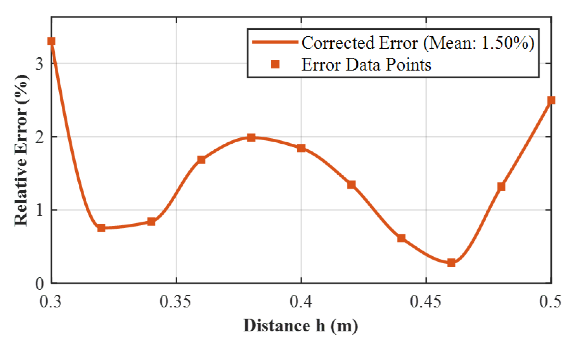
Figure 7.
Decay Curve of the Angular Velocity for the Spherical Shell.
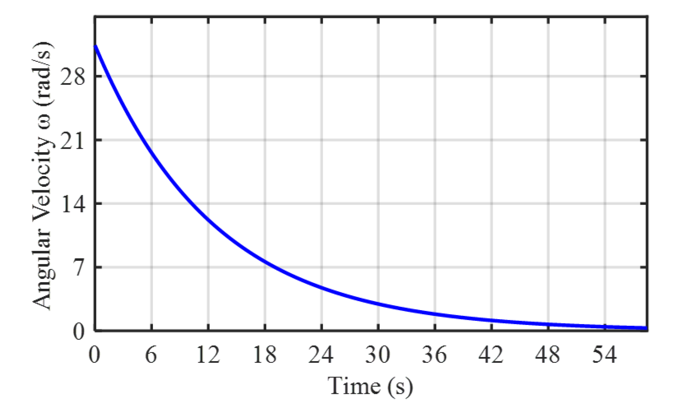
Figure 8.
Overview of the experimental platform.
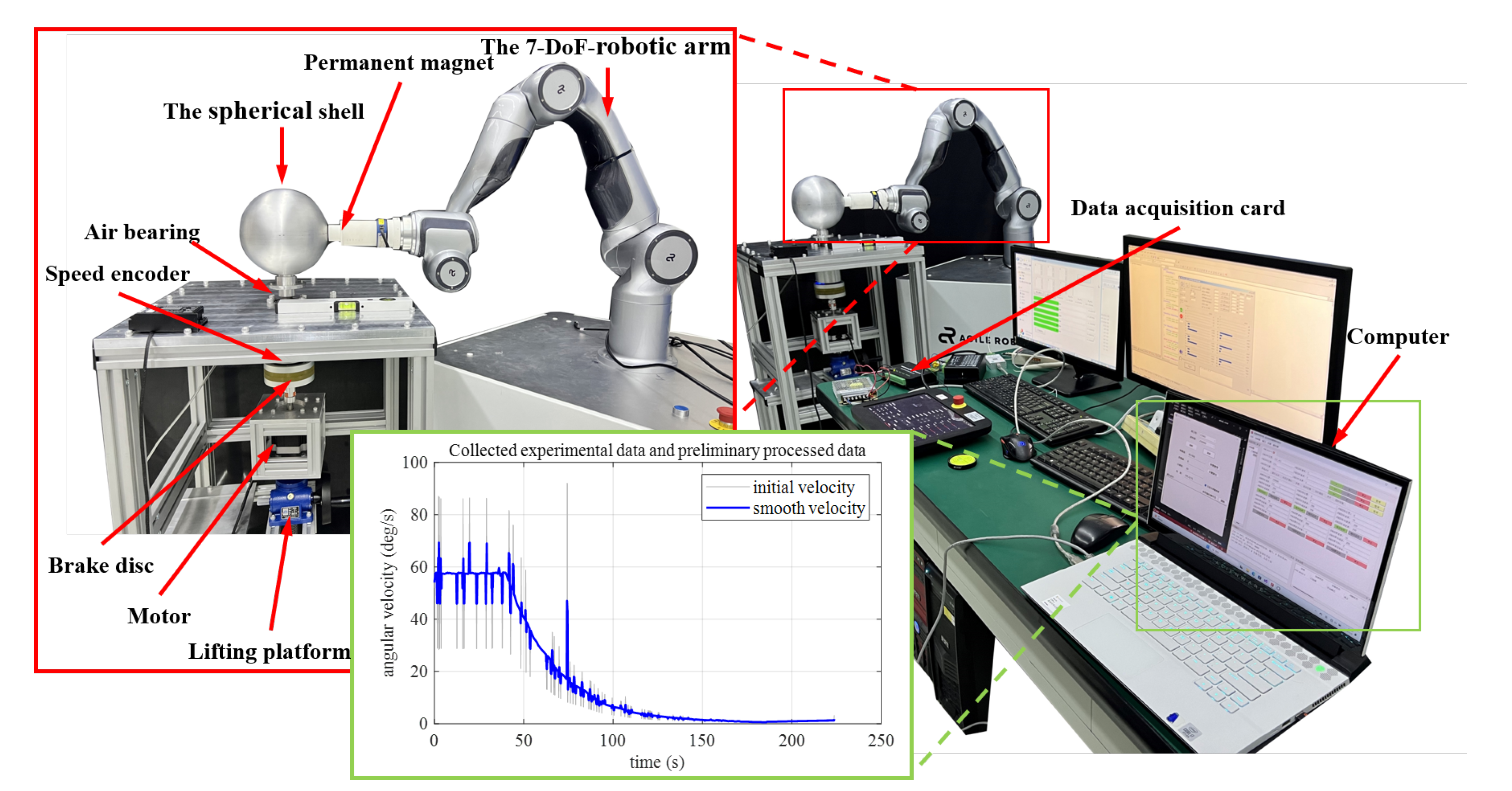
Figure 9.
Angular velocity decay curve of spherical shell in the absence of magnetic field
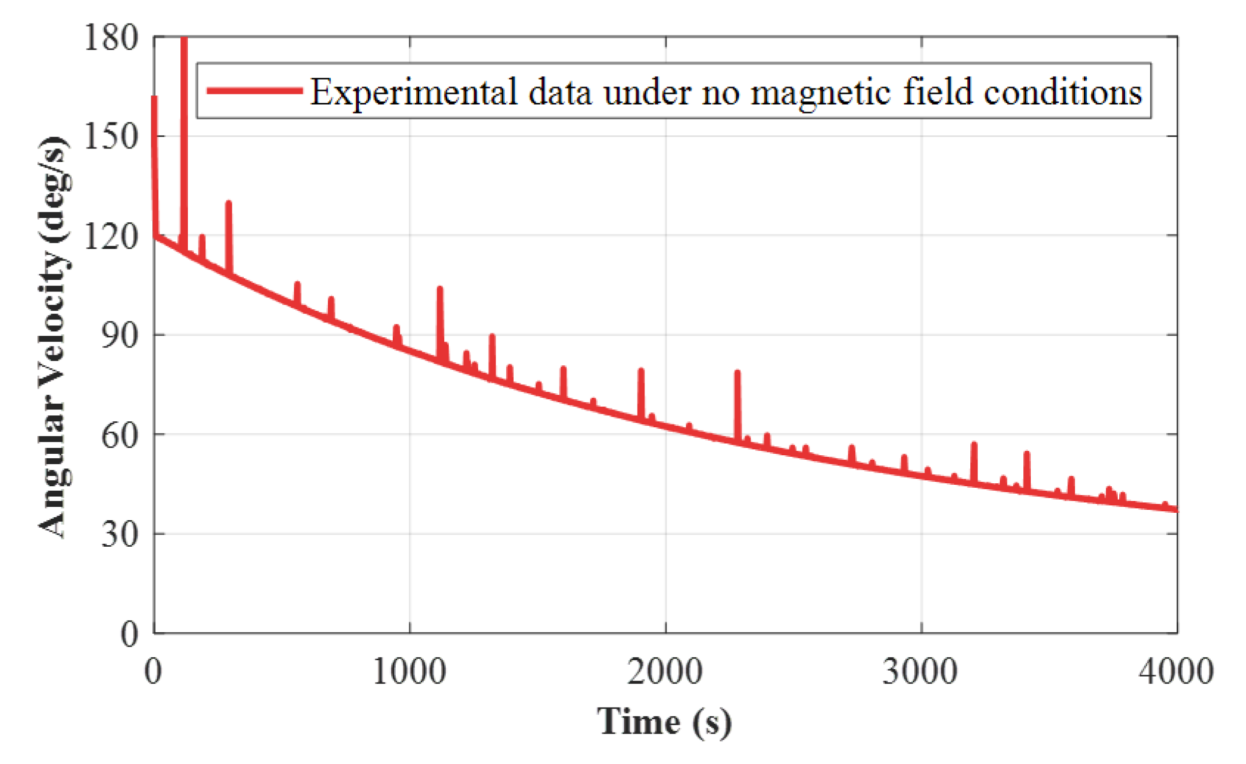
Figure 10.
Comparison of experimental data and corrected analytical model results under three distance conditions.
Figure 10.
Comparison of experimental data and corrected analytical model results under three distance conditions.
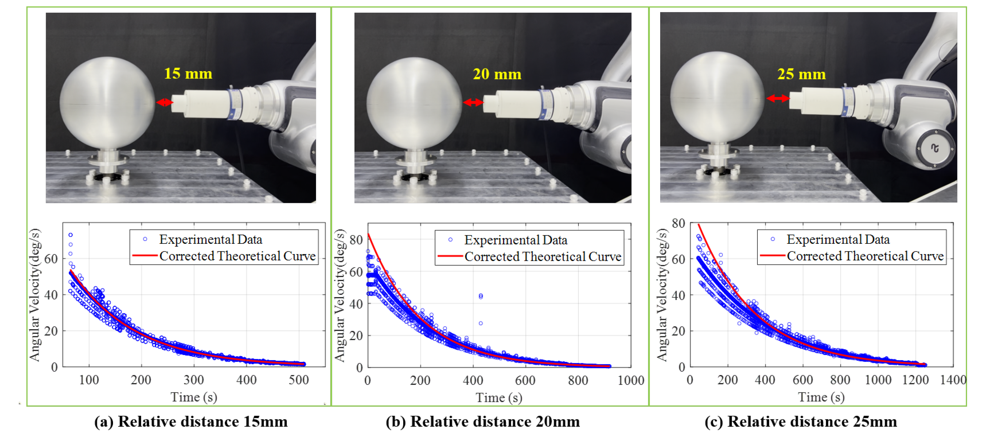
Table 1.
Parameters used of Numerical Calculation.
| Layer | Thickness (mm) | Radius (mm) | Grid Number |
|---|---|---|---|
| Outermost atmospheric | 240 | 600 | 104,652 |
| Target outer atmospheric | 120 | 360 | 156,978 |
| Magnetic dipole | 140 | 240 | 156,978 |
| Target | 4 | 100 | 52,326 |
| Target inner atmospheric | 20 | 96 | 69,768 |
| Inner core layer | 76 | 76 | 85,122 |
Table 2.
Finite Element Simulation Parameter Table.
| parameter | Value |
|---|---|
| Magnetic Dipole Moment (m) | |
| Dipole-to-shell distance (h) | 0.3-0.5 |
| Electrical Conductivity () | |
| Vacuum Permeability () | |
| Spherical Shell Thickness (e) | |
| Angular Velocity () | |
| Shell Radius (R) |
Disclaimer/Publisher’s Note: The statements, opinions and data contained in all publications are solely those of the individual author(s) and contributor(s) and not of MDPI and/or the editor(s). MDPI and/or the editor(s) disclaim responsibility for any injury to people or property resulting from any ideas, methods, instructions or products referred to in the content. |
© 2025 by the authors. Licensee MDPI, Basel, Switzerland. This article is an open access article distributed under the terms and conditions of the Creative Commons Attribution (CC BY) license (http://creativecommons.org/licenses/by/4.0/).
Copyright: This open access article is published under a Creative Commons CC BY 4.0 license, which permit the free download, distribution, and reuse, provided that the author and preprint are cited in any reuse.


