Submitted:
09 October 2025
Posted:
10 October 2025
You are already at the latest version
Abstract
Adsorption refrigeration machines (ARMs) offer a sustainable cooling solution by oper-ating with low electrical input and utilizing environmentally friendly refrigerants. Their compatibility with renewable energy sources makes them particularly suitable for inte-gration into clean energy systems, including hydrogen production processes. This study investigates the thermodynamic performance of an ARM through a parametric analysis focused on the influence of adsorption and desorption temperatures on system efficiency. The analysis is based on a dynamic thermodynamic model simulating the adsorption cycle under various temperature scenarios. Key performance indicators, such as the coef-ficient of performance (COP), cooling capacity, and thermal efficiency, are evaluated across a range of operating temperatures. Particular attention is given to the optimization of the desorption temperature, which critically affects energy consumption and the cooling demand required for hydrogen production via electrolysis or thermochemical processes. Results show that optimizing temperature parameters can significantly improve system performance. For instance, increasing the desorption temperature within an optimal range enhances the regeneration phase and maximizes the COP. The study identifies operating conditions that promote high thermal efficiency and effective coupling with hydrogen production cycles. These findings demonstrate the technical feasibility and energetic advantages of integrating adsorption refrigeration into hydrogen production systems. Such coupling not only reduces the total energy input but also supports the development of low-carbon, energy-efficient pathways for green hydrogen generation.
Keywords:
adsorption refrigeration machine (ARM)
; parametric study
; temperature influenc
; coefficient of performance (COP)
; cooling capacity
; hydrogen production
; energy efficiency
; thermal optimization
1. Introduction
Solar-driven adsorption refrigeration systems have gained increased attention in recent years due to their environmental compatibility and low energy requirements. These systems operate using natural refrigerants and are typically powered by low-grade thermal sources, including solar heat and industrial waste heat [1,2,3,4,5]. Their simplicity, scalability, and non-dependence on electricity make them suitable for off-grid cooling applications.
This study aims to develop a dynamic simulation model of a silica gel–water adsorption refrigeration machine using Simulink, focusing on the optimization of key operating parameters, particularly adsorption and desorption temperatures. The model is used to evaluate the system’s feasibility for integration into a hydrogen production process under Tunisian climatic conditions. The ultimate objective is to identify optimal thermal conditions that maximize system COP, cooling capacity, and energy efficiency in a sustainable and renewable configuration.
These systems are particularly suitable for rural or sun-rich regions such as North Africa [6]. The growing concern regarding greenhouse gas emissions, reinforced by international agreements such as the Montreal and Kyoto protocols, has further stimulated research in adsorption cooling as a clean alternative to conventional vapor-compression systems [7,8]. Solar energy, being abundant and diffusely distributed, offers a compelling energy input for such systems. However, its intermittency and dependence on environmental factors like geographic location, time of day, and atmospheric conditions require careful thermal management in practical applications [9,10].
Among various adsorbent–adsorbate pairs, the silica gel–water combination is widely studied due to its favorable thermophysical properties, including high adsorption capacity (up to 40% by dry mass) and regeneration capability at temperatures below 100 °C [11,12,13,14]. These characteristics make it highly compatible with solar heat and waste heat sources [15]. Recent investigations have explored the performance enhancement of silica gel-based systems via hybrid materials, composite adsorbents, and optimized heat exchangers [16,17,18,19].
Liu et al. demonstrated that a silica gel–water adsorption chiller could achieve cooling capacities above 6 kW with a coefficient of performance (COP) near 0.4 under suitable thermal conditions [20]. Later developments incorporating mass and heat recovery reported COP values up to 0.5 [21,22]. Similarly, two- and three-bed cycle configurations have been proposed to improve system continuity and reduce thermal downtime [23,24,25].
Moreover, the integration of adsorption cooling with other thermal systems—such as desalination units, combined cooling and power (CCHP), or hydrogen production—has emerged as a promising research direction. These hybrid systems optimize energy flows and improve the global efficiency of renewable energy utilization [26,27,28].
2. Materials and Methods
2.1. Working Principle of A Two-Bed Adsorption Chiller
An adsorption chiller operates on the basis of cyclic adsorption and desorption processes, driven by a low-grade heat source. In this system, an adsorbent material—typically silica gel—is used to alternately adsorb and desorb a refrigerant, commonly water vapor. The cycle begins with the desorption phase, wherein thermal energy is supplied to the adsorbent bed (desorber). This input heat—often derived from solar energy—causes the adsorbed water vapor to be released from the adsorbent matrix. The desorbed vapor subsequently flows into a condenser, where it is liquefied by releasing latent heat to a cooling medium.
The resulting condensate is then directed into an evaporator, operating under low pressure. In the evaporator, the liquid water absorbs heat from a chilled water loop or another cooling load, thereby producing the cooling effect. As the water evaporates, it is again drawn into another adsorbent bed (adsorber), which has been previously cooled using cooling water to facilitate the adsorption phase. This process is exothermic and must be continuously maintained to ensure proper cycle regeneration.
In a two-bed adsorption system, two adsorbent reactors (beds) operate alternately—one undergoing desorption while the other undergoes adsorption. This alternating mode ensures a quasi-continuous refrigeration output, thereby improving overall system performance and thermal stability.
In the case of a solar-driven configuration, the heat required for desorption is supplied by solar collectors. Solar radiation is absorbed and converted into thermal energy, which is stored in a thermal storage tank and delivered to the desorber via a circulating pump. The integration of solar energy aligns well with the temperature range required for silica gel–water systems, typically between 70–95 °C.
A key innovation in this study lies in the method of applying the adsorbent material: silica gel is directly coated onto the surfaces of the heat exchangers within the adsorption beds. This approach is adopted to significantly enhance heat transfer between the adsorbent and the thermal fluid. In conventional packed-bed systems, poor thermal contact between the metallic surfaces and granular adsorbents results in a high thermal resistance, which severely limits the effective utilization of the heat source and causes variability in the system performance. By contrast, the coated-bed configuration reduces thermal resistance and improves the thermal response of the adsorbent, thereby enhancing the system’s overall cooling capacity and coefficient of performance (COP).
A schematic diagram illustrating the cycle components and flow sequence is shown in Figure 1.
3. Analysis and Modelling
3.1. Assumptions
To develop a reliable and tractable mathematical model of the two-bed adsorption chiller, the following assumptions are made:
- Uniform distribution: The temperature, pressure, and the quantity of adsorbed water vapor are assumed to be spatially uniform within each adsorbent bed. This assumption simplifies the model to a lumped-parameter approach.
- Adiabatic insulation: All components, including the adsorber and desorber, are considered to be perfectly insulated, thus neglecting any heat losses to the ambient environment.
- Ideal vapor transport: The water vapor desorbed from the adsorbent is assumed to flow instantaneously and completely into the condenser, without accumulation or delay.
- Ideal condensate flow: The condensate from the condenser is assumed to flow immediately and without resistance into the evaporator.
- Instantaneous evaporation and adsorption: The liquid water entering the evaporator is presumed to evaporate instantaneously under vacuum conditions, and the generated vapor is assumed to be adsorbed instantaneously in the cooled adsorber bed.
- Phase modeling: The adsorbed water is considered to exist in liquid phase, while the water vapor behaves as an ideal gas. This allows the use of the ideal gas law in mass and energy balance equations.
- Negligible hydraulic resistance: Pressure losses and flow resistances in the pipelines and valves are neglected.
- Constant properties: The thermophysical properties of the adsorbent material, working fluid (water), heat exchanger tubes (metal), and water vapor are considered to be constant throughout the cycle.
These assumptions allow the simplification of the highly nonlinear, transient behavior of the system, making it possible to derive the governing energy and mass balance equations for each component (adsorber, desorber, evaporator, and condenser). The resulting model captures the essential thermal dynamics and provides a foundation for optimization and performance prediction.
Rate of Adsorption/desorption
The rate of adsorption or desorption is calculated by the linear driving force kinetic equation, The coefficients of LDF equation for silica gel/water are determined by Chihara and Suzuki and are given in the below:
The effective mass transfer coefficient inside the pores ks is given by:
The effective diffusivity is defined as follows
Where :
Dso= 2.54 10-4 m2/s, RP = 1.7 10-4 mEa = 4.2 104 J/mol, F0 = 15
R = 8,314 J/mol K
The equilibrium uptake of silica gel- water pair is estimated using the equation developed by Boelman.
Where Ps(Tr) and Ps(Ts) are respectively the corresponding saturated vapor pressures of the refrigerant at temperatures Tr (water vapor) and Ta (adsorbent). Ps for water vapor is estimated using the following equation:
Energy balance of adsorber
The adsorption energy balance is described by:
The outlet temperature of cooling water can be expressed as
Energy balance of desorber
The desorption energy balance is described by:
The outlet temperature of hot water can be expressed as
Energy balance of condenser
The condenser energy balance equation can be written as
The outlet temperature of cooling water can be expressed as
Energy balance of evaporator
The energy balance in the evaporator is expressed as
The outlet temperature of chilled water can be written as
Mass balance in the evaporator
The mass balance for the refrigerant can be expressed by neglecting the gas phase as:
Where, is the adsorbent mass.
System performance equations
The COP value is defined by the following equation:
The cooling capacity of the system is expressed by:
Where :
Specific Cooling Power
Simulation Parameters
| Parameter | Value |
| ma | 50 Kg |
| 〖∆H〗_ads | 2800 kJ/kg |
| L_v | 2500 kJ/kg |
| Ccd ,Cev, C_ad | 0.386 kJ/kg.K |
| 〖Cp〗_(r,v) | 1.85 kJ/kg.K |
| C_a | 0.924 kJ/kg.K |
| C_pr | 4.18 kJ/kg.k |
| m·_(f,ad) | 1.6 m3/h |
| m·_(f,cd) | 3.7 m3/h |
| m·_(f,ev) | 2 m3/h |
| T_(ev,in) | 15 °C |
| T_(cd,in) | 22 °C, |
| T_(gn,in) | 62 °C |
| t_cycle | 840 s |
The Carnot coefficient of performance is calculated by the following relation:
The adsorption efficiency of the machine is determined by:
4. Results
4.1. Experimental Setup
The experimental investigations were carried out using the ENERBAT platform, a solar-assisted tri-generation system installed at the University of Lorraine (Nancy, France), within the Faculty of Science and Technology. A schematic representation of the installation is presented in Figure 2.
ENERBAT is a comprehensive test bed designed to explore renewable energy integration into building thermal management systems. It combines solar thermal energy, gas-based cogeneration, and adsorption refrigeration in a unified platform, thereby enabling the simultaneous generation of cooling, heating, and electricity.
The core components of the platform include:
- A field of solar thermal collectors, responsible for harnessing solar energy and converting it into heat.
- A stratified thermal storage tank, used to store hot water generated by the solar collectors for subsequent use in desorption and domestic heating.
- A gas-fired cogenerator, based on an internal combustion engine, which produces both electricity and thermal energy. The recovered heat is used either for space heating or to supply the adsorption chiller.
- An adsorption refrigeration machine (ARM), which is activated by the thermal energy from the solar tank or cogenerator and delivers chilled water for air-conditioning applications.
- Expansion vessels for system safety, and hydraulic pumps to ensure fluid circulation between components.
- Plate heat exchangers to improve heat transfer in various loops.
- A climatic chamber, constructed from solid glued laminated timber, which consists of two thermally separated compartments, each with a volume of 27 m³. One chamber is conditioned using a chilled ceiling for cooling, while the other uses a heated floor for space heating.
This configuration enables the analysis of dynamic interactions between heat production, storage, and consumption under real environmental conditions, and facilitates the evaluation of the ARM’s performance in a building-integrated application. The integration of adsorption cooling into the tri-generation system serves as a demonstrator for sustainable thermal management in buildings using low-exergy and renewable resources.
Model Validation
The accuracy of the developed dynamic model was assessed by comparing simulated results with experimental data obtained under standard operating conditions. Figure 3 presents the time-evolution profiles of the inlet and outlet temperatures of the heat transfer fluids at key locations in the system: hot water loop, cooling water loop, and chilled water loop.
During the startup phase, the outlet temperature of the hot water loop gradually increases and reaches the inlet temperature after approximately 7 minutes. This stabilization indicates that the silica gel in the desorber has been fully heated, allowing effective desorption of water vapor. At this point, the thermal energy required by the system reaches a minimum, as the energy is now primarily consumed in phase change processes rather than in raising the adsorbent temperature.
In the cooling water circuit, the inlet temperature rises during the pre-cooling and pre-heating periods, and then drops during the desorption/condensation phase. This behavior reflects the system’s need to remove latent heat from the condenser during condensation, as well as from the adsorbent during desorption. The observed cooling of the fluid during these periods confirms effective energy extraction by the cooling loop.
For the evaporator (chilled water loop), the outlet temperature increases during the evaporation/adsorption phase, corresponding to the system delivering cooling power to the thermal load. Conversely, during switching phases (pre-cooling and pre-heating), the chilled water temperature decreases, as evaporation is temporarily halted and no significant cooling is being provided.
Overall, the numerical model successfully reproduces the dynamic thermal behavior observed experimentally, capturing the transient temperature responses in all loops. The consistency between simulated and measured results confirms the validity of the model assumptions and its applicability for parametric studies and optimization of system performance.
Parametric Study of the Adsorption Chiller
The performance of an adsorption refrigeration machine (ARM) is strongly influenced by the temperatures of the working fluids: hot water (driving heat source), cooling water (heat sink), and chilled water (cooling load). This section investigates the impact of hot water inlet temperature on the cooling capacity and the coefficient of performance (COP), under varying cooling water inlet temperatures.
Effect of Cooling and Heating Water Temperatures
A reduction in cooling water inlet temperature enhances both the adsorption rate and the heat rejection process in the adsorber and condenser, leading to an increase in the cooling capacity and an improvement in COP. Conversely, an increase in hot water inlet temperature accelerates the desorption process, increasing the quantity of refrigerant vapor generated and subsequently the refrigeration effect. This leads to an increase in cooling capacity (SCP, specific cooling power). However, depending on the level of the cooling water temperature, this may also result in diminished COP, especially if the thermal energy input outweighs the gain in useful cooling effect.
Effect of Hot Water Inlet Temperature
Figure 4 illustrates the variation of the specific cooling power (SCP) and the coefficient of performance (COP) as functions of the hot water inlet temperature, under different cooling water temperature conditions. All other operating parameters—including cycle duration, chilled water inlet temperature, and flow rates—were maintained at their nominal design values.
As the hot water inlet temperature increases from 55 °C to 95 °C, a consistent enhancement in cooling capacity is observed for all tested cooling water inlet temperatures. This is attributed to the increased desorption rate at higher temperatures, resulting in a greater quantity of refrigerant vapor being released from the adsorbent and consequently an increased evaporation and adsorption capacity in the subsequent cycle.
With respect to COP, a gradual increase is also recorded as the hot water temperature rises, particularly in the range of 55 °C to 85 °C. This is explained by the improved thermal driving force that boosts both desorption and the overall system cooling effect. However, beyond 85 °C, the COP stabilizes or shows diminishing returns, as the additional heat input does not proportionally increase the refrigerant circulation. This suggests the existence of an optimal desorption temperature, beyond which energy efficiency gains become negligible.
These findings highlight the importance of thermal input optimization in solar-assisted or waste-heat-driven adsorption systems, especially when integrated with intermittent renewable energy sources. The optimal balance between heating and cooling conditions must be maintained to maximize both cooling performance and system efficiency.
It is evident from the results that the sorption dynamics are significantly enhanced at higher hot water inlet temperatures. An increase in the driving temperature intensifies the desorption rate, leading to a more rapid liberation of the adsorbed refrigerant. This accelerated desorption enhances thermal exchange within the adsorbent bed and ensures a greater quantity of refrigerant is made available prior to the evaporation/adsorption phase, thereby improving the system’s refrigeration capacity.
Conversely, lower cooling water inlet temperatures yield a notable improvement in both specific cooling power (SCP) and the coefficient of performance (COP). This behavior is attributed to two key mechanisms: first, faster condensation of the desorbed refrigerant due to enhanced heat rejection in the condenser; and second, the increased adsorption rate, which is favored by lower adsorbent temperatures. Both effects contribute to a more efficient refrigeration cycle and improved overall performance.
Furthermore, the thermodynamic efficiency of the adsorption chiller was evaluated by comparing the actual COP to the theoretical maximum COP defined by the inverse Carnot cycle. The ratio between the actual and ideal COPs is presented in Figure 5, offering insight into the exergetic efficiency of the system under various thermal operating conditions. This metric serves as a valuable indicator of how closely the real system approaches ideal thermodynamic performance.
The thermodynamic efficiency of the adsorption chiller is significantly influenced by both the hot water inlet temperature and the cooling water inlet temperature. As observed in Figure 5, increasing the temperature of the heat source (hot water) and decreasing the temperature of the heat sink (cooling water) both lead to a measurable improvement in system efficiency.
This trend is primarily explained by thermodynamic and kinetic factors. An increase in the condenser temperature (due to higher cooling water temperatures) leads to a rise in the saturation pressure of the refrigerant, denoted as Ps(Tcd)P_s(T_{cd})Ps(Tcd). This, in turn, affects the adsorption–desorption equilibrium, increasing the amount of refrigerant mass regenerated during desorption. However, while this enhances the cycled mass, it also reduces the overall thermal efficiency, as more heat is required for desorption without a proportional gain in useful cooling. Thus, a higher condenser temperature may decrease the effective COP, especially under suboptimal cooling water conditions.
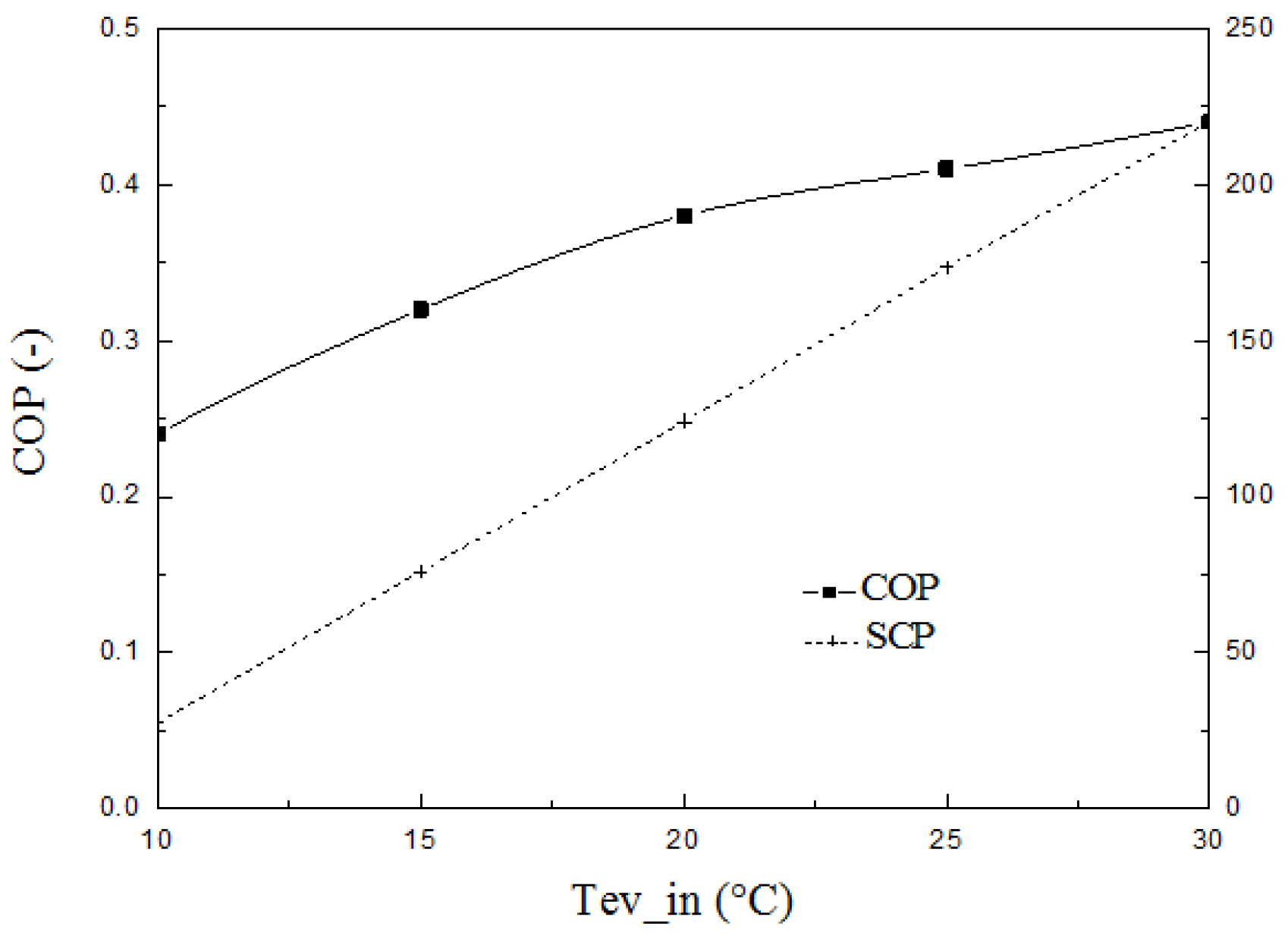
Effect of Chilled Water Inlet Temperature
To evaluate the influence of chilled water conditions, a series of simulations were conducted by varying the inlet temperature of the chilled water (evaporator side), while keeping the hot water temperature fixed at 85 °C and the cooling water inlet temperature at 40 °C.
Figure 6 illustrates the variation of coefficient of performance (COP) and specific cooling power (SCP) with respect to the evaporator inlet temperature. Results show that increasing the evaporator temperature enhances both COP and SCP. Specifically, a 20 °C increase in evaporator inlet temperature results in a COP increase of 0.2 and an SCP gain of 0.481 kW/kg.
This performance enhancement is attributed to a higher evaporation rate at elevated temperatures, which increases the vapor pressure inside the evaporator, promoting greater refrigerant uptake during the subsequent adsorption phase. As the evaporator pressure rises, the driving potential for mass transfer increases, resulting in higher adsorption capacity at the end of the adsorption cycle. Consequently, both the cooling effect and the efficiency of the cycle improve.
These findings highlight the critical importance of evaporator temperature control in optimizing adsorption chiller performance, particularly in systems operating under variable thermal loads or ambient conditions.
4. Discussion
Coupling Adsorption Cooling with Green Hydrogen Production
One of the main limitations of solar-driven adsorption cooling systems lies in their intermittent operation, particularly during nighttime or periods of low solar irradiance. Even with the inclusion of thermal energy storage systems such as hot water tanks, maintaining a continuous and stable cooling output remains a challenge.
To overcome this issue and enhance energy autonomy, a promising strategy involves the coupling of the adsorption chiller with a green hydrogen production system. In such a configuration, hydrogen is generated from renewable energy sources (e.g., solar photovoltaics or wind turbines) through water electrolysis, and then stored for use during off-peak or non-solar periods.
The stored hydrogen can subsequently be converted into electrical or thermal energy using fuel cells or hydrogen-compatible boilers. This allows the system to supply the necessary thermal input for desorption, even in the absence of direct solar energy, thereby ensuring uninterrupted cooling throughout the day and night.
Moreover, the electrolysis process itself offers an opportunity for thermal integration. Electrolyzers, especially alkaline or PEM types, typically operate at moderate temperatures (50–80 °C), generating substantial waste heat. Instead of discarding this low-grade thermal energy, it can be recovered and redirected to regenerate the adsorbent in the chiller during the desorption phase. This enhances the overall system efficiency, reduces heat rejection to the environment, and minimizes the dependency on external heat sources.
Such a synergistic integration presents several benefits:
- Improved system flexibility and operational stability.
- Maximized utilization of available thermal and electrical energy.
- Reduced carbon footprint, by relying exclusively on renewable-based sources.
- Enhanced potential for off-grid or microgrid applications, especially in remote or arid regions where solar resources are abundant but cooling demand is high.
Integrating adsorption cooling with green hydrogen production represents a technologically viable and environmentally sustainable solution. It offers an innovative pathway toward flexible, autonomous, and low-emission cooling systems, well aligned with future energy transition goals and the development of multi-energy systems.
5. Conclusions
This work presented a dynamic and parametric investigation of a solar-powered adsorption refrigeration system using the silica gel–water working pair, with the objective of evaluating its performance under varying thermal conditions and assessing its potential integration with hydrogen production systems. A numerical model was developed and validated to simulate heat and mass transfer phenomena in a two-bed configuration. The parametric study revealed that increasing the hot water inlet temperature (optimal range: 80–95 °C) enhances desorption and boosts cooling capacity, while lowering the cooling water temperature significantly improves the COP—especially under geothermal conditions where values up to 0.7 can be achieved. Additionally, raising the evaporator temperature increases refrigerant uptake, resulting in improved SCP and COP, which confirms the critical role of evaporator-side thermal control. The system showed strong suitability for the Tunisian climate, offering COPs ranging from 0.25 to 0.54 under aerothermal conditions and reaching up to 0.7 with geothermal assistance. Finally, by proposing a coupling with green hydrogen production systems, this study demonstrates that waste heat from electrolysis can be effectively recovered to sustain desorption processes, ensuring continuous cooling even in the absence of solar input. This hybrid configuration enhances energy autonomy, reduces overall consumption, and supports the development of integrated, low-carbon energy infrastructures
Author Contributions
Conceptualization, N.G. and M.E.; methodology, N.G. and R.B.; validation, N.G., M.E. and S.G.; formal analysis, N.G.; investigation, N.G. and R.B.; resources, S.G.; data curation, N.G.; writing—original draft preparation, N.G.; writing—review and editing, M.E., R.B. and S.G.; visualization, N.G.; supervision, M.E. and S.G.; project administration, S.G. All authors have read and agreed to the published version of the manuscript.
Funding
This research received no external funding.
Data Availability Statement
No new data were created or analyzed in this study. Data sharing is not applicable to this article
Conflicts of Interest
The authors declare no conflicts of interest. The funders had no role in the design of the study; in the collection, analyses, or interpretation of data; in the writing of the manuscript; or in the decision to publish the results.
References
- Almohammadi, A.; Riahi, A.; El-Shafie, M.; Khosravi, A. Operational conditions optimization of a proposed solar-powered adsorption cooling system: Experimental, modeling, and optimization algorithm techniques. Energy 2021, 206, 118007. [Google Scholar] [CrossRef]
- Jalil, M.A.; Sidik, N.A.C.; Samion, S.; Kadirgama, K. Effect of adsorbent configuration on performance of a continuous solar adsorption chiller. Renew. Energy 2020, 158, 360–373. [Google Scholar] [CrossRef]
- Elsheniti, M.B.; Abdelrahman, A.K.; Shatat, M. Performance of a solar adsorption cooling and desalination system using aluminum fumarate and silica gel. Appl. Therm. Eng. 2021, 194, 117085. [Google Scholar] [CrossRef]
- Khatibi, J.; Taherian, H.; Momeni, M. Optimal aluminum additive loading in finned heat exchangers for adsorption systems. Appl. Therm. Eng. 2021, 196, 117267. [Google Scholar] [CrossRef]
- Ng, W.P.Q.; Tay, K.H.; Shahzad, M.W.; Ng, K.C. Field synergy analysis for heat/mass transfer in adsorption-based desalination. Desalination 2020, 517, 115226. [Google Scholar]
- Islam, M.A.; Mahbub, M.; Rahman, M. Thermophysical properties of silica gels for adsorption cooling. Int. J. Refrig. 2020, 110, 277–285. [Google Scholar] [CrossRef]
- Denzinger, C.; Reimann, A.; Alefeld, G. Life cycle assessment of a solar adsorption refrigerator. Int. J. Refrig. 2021, 121, 105–113. [Google Scholar] [CrossRef]
- Lu, Z.; Wang, R.Z.; Xia, Z.Z. Solar heat pipe silica gel–water adsorption chiller with recovery. Appl. Therm. Eng. 2013, 50, 1015–1025. [Google Scholar] [CrossRef]
- Chakraborty, A.; Saha, B.B.; Aristov, Y.I. Effect of grain size on dynamic performance of silica gel-based chillers. Energy 2020, 78, 304–312. [Google Scholar] [CrossRef]
- Rocky, K.A.; Saha, B.B.; Tay, K.H. Specific heat capacity of parent and composite adsorbents. Appl. Therm. Eng. 2020, 164, 114438. [Google Scholar] [CrossRef]
- Liu, Y.L.; Wang, R.Z.; Xia, Z.Z. Experimental performance of a silica gel–water adsorption chiller. Appl. Therm. Eng. 2005, 25, 359–375. [Google Scholar] [CrossRef]
- Sah, R.P.; Choudhury, B.; Das, R.K. Comparative study of waste-heat driven silica gel adsorption systems. J. Energy Storage Appl. 2024, 57, 212–222. [Google Scholar]
- Woo, M.W.; Ng, K.C. Hybrid adsorption desalination and cooling using silica gel. Desalination 2019, 467, 136–144. [Google Scholar] [CrossRef]
- Mitra, S.; Ng, K.C. Solar-driven adsorption desalination system. Energy Procedia 2014, 49, 2261–2270. [Google Scholar] [CrossRef]
- Uddin, K.; Ahmed, S.; Saha, B.B. Heat capacities of carbon-based adsorbents for heat pumps. Appl. Therm. Eng. 2018, 129, 117–126. [Google Scholar] [CrossRef]
- Henninger, S.K.; Erhard, S.; Müller, D. Water vs methanol in silica gel chillers: A model-based study. Appl. Therm. Eng. 2023, 236, 121816. [Google Scholar] [CrossRef]
- Sha, H.; Li, Z.; Wang, J. Performance of consolidated carbon-based adsorbents in heat pumps. Appl. Therm. Eng. 2022, 217, 119100. [Google Scholar]
- Dias, R.; Silva, A.M.; Martins, N. Full system modeling of adsorption heat pump. Appl. Therm. Eng. 2022, 213, 118792. [Google Scholar] [CrossRef]
- Jahan, I.; Saha, B.B.; Chakraborty, A. Effect of metal doping on aluminum fumarate sorbents. Heat Transf. Eng. 2021, 42, 421–431. [Google Scholar]
- Ramesh, P.S.; Choudhury, B.; Das, R.K. Performance analysis of two-bed silica gel chiller. Int. J. Sustain. Energy 2016, 37, 30–46. [Google Scholar]
- Tso, C.Y.; Chao, C.Y.H. Composite adsorbents for enhanced adsorption cooling performance. Energy Convers. Manag. 2012, 55, 71–77. [Google Scholar]
- Boelman, E.C.; Saha, B.B.; Kashiwagi, T. Performance of silica gel–water chiller with heat recovery. Int. J. Refrig. 1995, 18, 239–246. [Google Scholar]
- Miyazaki, T.; Akisawa, A.; Kashiwagi, T. Three-bed adsorption cooling system performance. Energy 2010, 35, 967–972. [Google Scholar]
- Sapienza, A.; et al. Cycle optimization in zeolite-based adsorption cooling. Appl. Energy 2011, 88, 4833–4842. [Google Scholar]
- Chong, D.Y.R.; Saha, B.B.; Ng, K.C. Comparative study of working pairs for low-temperature adsorption. Appl. Therm. Eng. 2020, 172, 115147. [Google Scholar]
- Hassan, A.A.; Mohamed, E.A.; Ramadan, M.K. Integrated adsorption multigeneration systems. Int. J. Refrig. 2020, 116, 129–145. [Google Scholar] [CrossRef]
- Xu, Y.; Zhang, H.; Liu, J. 4E analysis of SOFC-CCHP system with LiBr chiller. Energy Rep. 2022, 8, 5284–5295. [Google Scholar] [CrossRef]
- Gimelli, A.; et al. Energy-economic feasibility of battery-CCHP hybrid with adsorption unit. Energy 2025, 317, 134640. [Google Scholar]
- Abedi, M.; Jamei, A.; Asadi, M. Feasibility of solar chimney humidification–dehumidification. Renew. Energy 2023, 202, 88–102. [Google Scholar]
- Tran, M.T.; Nguyen, T.H. Efficient solar thermal water-splitting hydrogen production: A review. WIREs Energy Environ. 2024, 13, 1. [Google Scholar] [CrossRef]
Figure 1.
Schematic diagram of the double bed solar-powered adsorption chiller.
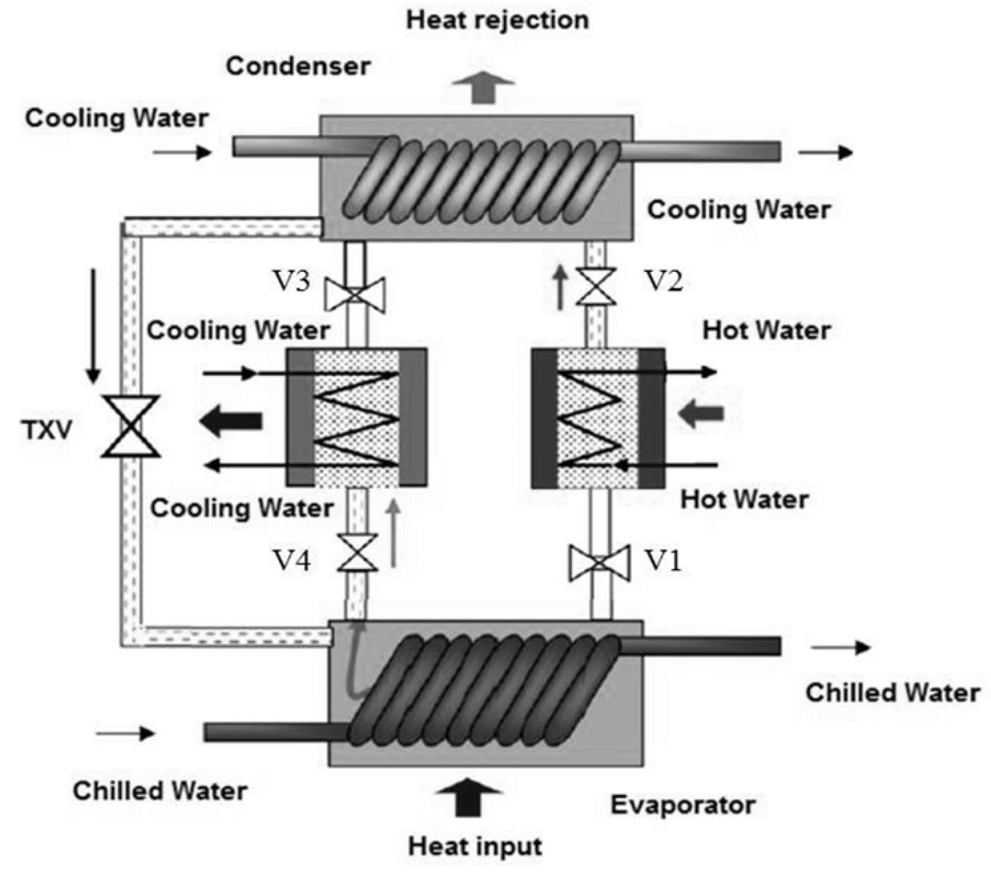
Figure 2.
Experimental setup.
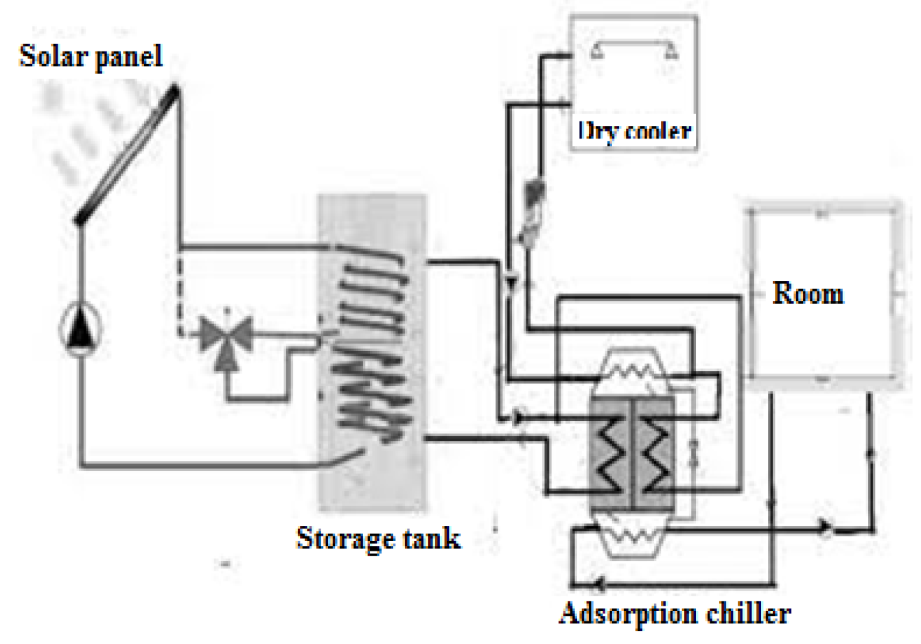
Figure 3.
Overall outlet temperature profile of heat transfer fluid for two beds adsorption chiller.
Figure 3.
Overall outlet temperature profile of heat transfer fluid for two beds adsorption chiller.

Figure 4.
Generation temperature influence on chiller COP and SCP (Tev_in=15 °C, tcycle=840s).
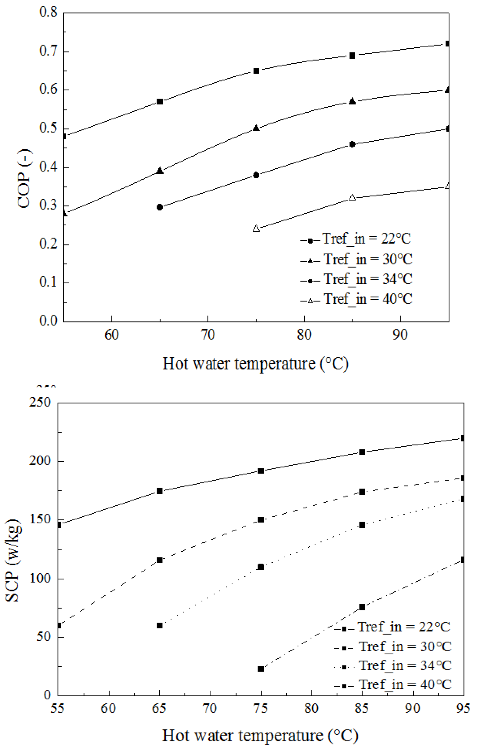
Figure 5.
Generation temperature influence on chiller efficiency (Tev_in=15 °C, tcycle=840s).
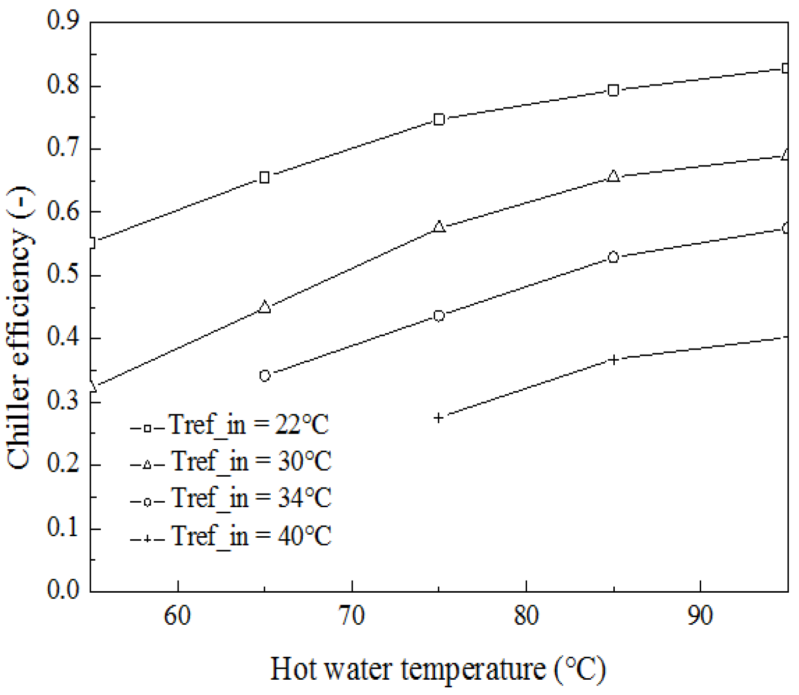
Figure 6.
Effect of chilled water inlet temperature on COP and SCP (Tref_in=40 °C, Tde_in=85 °C, tcycle=840s).
Figure 6.
Effect of chilled water inlet temperature on COP and SCP (Tref_in=40 °C, Tde_in=85 °C, tcycle=840s).
Disclaimer/Publisher’s Note: The statements, opinions and data contained in all publications are solely those of the individual author(s) and contributor(s) and not of MDPI and/or the editor(s). MDPI and/or the editor(s) disclaim responsibility for any injury to people or property resulting from any ideas, methods, instructions or products referred to in the content. |
© 2025 by the authors. Licensee MDPI, Basel, Switzerland. This article is an open access article distributed under the terms and conditions of the Creative Commons Attribution (CC BY) license (http://creativecommons.org/licenses/by/4.0/).
Copyright: This open access article is published under a Creative Commons CC BY 4.0 license, which permit the free download, distribution, and reuse, provided that the author and preprint are cited in any reuse.


