
Submitted:
26 August 2025
Posted:
28 August 2025
You are already at the latest version
Abstract
This study investigates hydrogen storage enhancement through adsorption in porous materials by coupling the Dubinin-Astakhov (D-A) adsorption model with H₂ conservation equations (mass, momentum, and energy). The resulting system of partial differential equations (PDEs) was solved numerically using the finite element method (FEM). Experimental work using activated carbon as an adsorbent was carried out to validate the model. The comparison showed good agreement in terms of temperature distribution, average pressure of the system, and the amount of adsorbed hydrogen (H₂). Further simulations with different adsorbents indicated that compact metal-organic framework (MOF-5) is the most effective material in terms of H₂ adsorption. Additionally, the pair (273 K, 800 s) remains the optimal combination of injection temperature and time. The findings underscore the prospective advantages of optimized MOF-5-based systems for enhanced hydrogen storage. These systems offer increased capacity and safety compared to traditional adsorbents. Subsequent research should investigate multi-objective optimization of material properties and system geometry, along with evaluating dynamic cycling performance in practical operating conditions. Additionally, experimental validation on MOF-5-based storage prototypes would further reinforce the model's predictive capabilities for industrial applications.
Keywords:
H2 adsorption
; H2 strorage
; porous media
; CFD
; heat transfer
; fluid mechanics
1. Introduction
In recent decades, the reliance on fossil fuels has revealed significant limitations due to increasing global demand, diminishing reserves, and the rising cost of petroleum-based energy. These factors have accelerated the shift toward renewable energy sources. Due to highly abundant and friendly environmental nature.
The storage of compressed gas entails the high-pressure storage of hydrogen (350-700 bar), predominantly in composite cylinders for various applications such as fuel cell electric vehicles (FCEVs) [1]. This technology is well-established and widely available on the market; nevertheless, it necessitates durable containment systems and involves substantial energy expenses for compression.
In contrast, liquid hydrogen storage involves cryogenic liquefaction at -253 °C. Although it allows for higher energy density, this approach is associated with elevated energy consumption, consuming up to 30% of the hydrogen’s usable energy content, and experiences boil-off losses during storage and manipulation [2].
Solid-state storage in the form of metal hydrides, nanoporous materials, or metal-organic frameworks (MOFs) has been extensively investigated for its potential to reversibly absorb and release hydrogen at moderate pressures and temperatures [3]. These materials offer improved safety and lower operating pressures. Nevertheless, their practical application is constrained by high material costs, limited hydrogen storage capacity by weight, and challenges related to kinetics and thermal management. The research encompasses both experimental and numerical investigations, spanning fundamental understanding and process enhancement of hydrogen adsorption systems.
Mahmoudi and Rahimi [4] studied experimentally and numerically the thermal performance of a metal hydride tank coupled with a fuel cell, focusing on the effects of heat pipe type, number, fins, and copper wire wicks. Results show good agreement between experiments and CFD simulations (deviations <8%), with sensitivity analysis revealing the boiling limit as a key factor in heat pipe performance. Briki et al [5] combine experimental P-C-T isotherm measurements and numerical modeling to analyze hydrogen absorption/desorption in LaNi₄.₄Fe₀.₃Al₀.₃ alloy. Thermodynamic parameters, including internal energy, entropy, and Gibbs free energy, are derived and studied as functions of temperature and pressure, revealing energy ranges of (absorption) and (desorption).
Elkhatib and Louahlia, [6] experimentally and numerically analyse hydrogen storage in a La₀.₉Ce₀.₁Ni₅ metal hydride tank coupled with a PEM fuel cell, focusing on the effects of varying cooling/heating conditions and charging pressures. Results show that lower cooling temperatures and higher hydrogen pressures enhance absorption rate and storage efficiency, with the state of charge increasing by cooling and discharge by heating.
Harrat et al [7] examine the hydrogen storage performance of LaNi₃.₆Al₀.₄Mn₀.₃Co₀.₇ alloy, highlighting the effects of temperature and pressure on absorption capacity. Structural, thermal, and morphological analyses confirmed a multiphase composition, with maximum hydrogen uptake of achieved at and , demonstrating the material’s suitability for efficient hydrogen storage.
Because it simplifies complex physical systems under justified assumptions: uniform properties (temperature, pressure, concentration) within each “lump” or control volume, the lumped parameter model (LPM) can be highly beneficial in studying and optimizing hydrogen (H₂) adsorption systems. Wang and Brinkerhoff [8] present a low-cost (LPM) for simulating hydrogen storage in solid-state materials, treating the system as a transient thermal RC network. Validated against CFD for both chemisorptive and physisorptive materials, the LPM predicts key thermofluidic parameters with error while drastically reducing computational cost and time. Xiao et al [9] develop a LPM for cryo-adsorptive hydrogen storage, incorporating variational isosteric heat based on the Dubinin–Astakhov isotherm and liquid–gas nitrogen interface dynamics to enhance accuracy. Validated against experiments and 2D simulations, the model effectively predicts charge–discharge behavior and enables performance optimization under varying flow rates.
When there is the need to captures spatial variations in Flow fields of hydrogen gas through porous adsorbent beds. Temperature gradients caused by exothermic adsorption. Mass transfer limitations inside adsorbent particles or across interfaces. Computational Fluid Dynamics (CFD) is a powerful tool. In this field numerous studies have been conducted, notably by Xiao et al al [10,11,12,13], who carried out a series of numerical investigations, primarily based on the finite element method. Their work focused on modeling temperature and pressure fields, the amount of adsorbed hydrogen, as well as various parameters influencing the adsorption process.
Hydrogen adsorption, particularly on materials such as metal-organic frameworks (MOFs) and activated carbon, is an exothermic process that releases heat. This heat accumulation can adversely affect adsorption efficiency by shifting the system away from optimal operating conditions. Phase change materials (PCMs) offer an effective thermal management solution by absorbing excess heat during adsorption as they undergo a solid-to-liquid phase transition. During desorption, as the PCMs revert to their solid state, they release the stored latent heat, thereby mitigating temperature fluctuations. This thermal buffering effect maintains the adsorbent within an optimal temperature range, ultimately enhancing hydrogen uptake capacity and improving cycling stability. Yao et al [14] developed a modified metal hydride reactor model incorporating phase change material (PCM) improves the accuracy of simulating continuous hydrogen absorption/desorption processes. Experimental validation and parametric optimization show enhanced hydrogen storage efficiency up to and reduced absorption time , attributed to improved heat transfer. Arslan et al [15] experimentally investigates hydrogen charge/discharge in a LaNi₅-based metal hydride reactor with and without integrated phase change material (PCM). Results show that the hybrid MH-PCM system enhances thermal management and hydrogen storage performance, offering potential for mobile hydrogen storage applications. Ye et al [16] numerically investigate different PCM configurations in magnesium hydride storage tanks to enhance heat transfer and hydrogen storage efficiency. Results show that sandwiched MH-PCM units offer superior performance due to reduced thermal resistance, with optimal PCM mass achieving a maximum gravimetric hydrogen storage capacity of and a increase in desorption rate. Chibani et al [17] optimize heat transfer in a large-scale activated carbon (AX-21) hydrogen storage reactor by integrating paraffin RT22HC as a phase change material and evaluating four metal fin types. Results show that copper fins significantly enhance PCM melting (by ) and heat transfer ( improvement), while reactor inclination angles have minimal impact, emphasizing the role of fin material and system design in improving energy storage performance.
Zelenak and Saldan review [18] the strategies to enhance H₂ uptake including optimizing surface area, pore volume, and isosteric enthalpy and proposes nanoconfinement of metal hydrides in MOFs as a breakthrough approach, with MOF-metal nanocomposites emerging as key future candidates. Process optimization efforts were specifically focused on geometry enhancements, thus Peng et al [19] demonstrates that triply periodic minimal surface (TPMS) structures significantly enhance hydrogen storage performance in metal hydride (MH) adsorbent beds compared to conventional finned designs. Yielding to lower average bed temperatures (+ cooling efficiency), higher hydrogenation fractions , and greater adsorption capacities . Wang et al integrate a high-thermal-conductivity fins into conventional CAH₂ tanks to enhance heat and mass transfer and reduce localized heat accumulation [20]. Other alternative approach involves integrating helical cooling tubes to enhance thermal management. Singh et al [21] develope a 3D model and prototype of a cylindrical hydrogen storage device with annular finned-tube heat exchangers for LaNi₅ metal hydride, achieving full hydrogen absorption in at . Parametric analyses of fin geometry and cooling conditions () demonstrate their critical impact on sorption kinetics. Wang et al [22] propose a combined solution (pre-cooling, fins, and targeted cooling tubes) that cuts adsorption time by and boosts storage capacity by by optimizing heat/mass transfer and avoid efficiency reduction due to localized hot spots in hydrogen adsorption tanks.; Huang et al [23] present a thermal management method combining central/spiral cooling tubes with vacuum insulation to enhance temperature uniformity in cryo-adsorption hydrogen storage. Numerical results demonstrate improved performance, with activated-carbon cryo-adsorption offering 2.5 times and 10 times higher capacity than cryo-compressed and ambient storage, respectively.
Wang et al 2024 [24] use a mathematical model and finite element analysis to optimize high thermal conductivity fin designs in activated carbon cold adsorbed hydrogen (CAH2) storage tanks. Results show that fins enhance heat transfer and adsorption uniformity, improving storage efficiency by ~40%, with optimal fin length at 30 mm and diminishing returns beyond 14 fins, while increased fin width reduces tank volume and storage capacity.
Wang et al 2025 [25] develop a dynamic adsorption model to address heat and mass transfer inefficiencies in activated carbon hydrogen tanks, proposing a targeted delivery tube to supply pre-cooled hydrogen to weak-adsorption zones. Combining inlet pre-cooling, fins, and targeted tubes significantly enhances thermal management, reducing adsorption time by and increasing storage capacity by compared to the original design.
Shabbani et al [26] investigates hydrogen purification from a surrogate gas using spent coffee grounds as an adsorbent, modeled with Aspen software under various thermal conditions. Results demonstrate that a rectangular non-adiabatic plate column significantly enhances hydrogen purity and recovery compared to a conventional cylindrical column.
Peng et al [27] evaluate the enhancement of adsorption-based hydrogen storage using metal hydrides (MHs) by incorporating high thermal conductivity triply periodic minimal surface (TPMS) structures in the adsorbent bed. Results indicate that TPMS structures reduce the average bed temperature, increase the hydrogenation fraction, and boost adsorption capacity compared to fin-based designs, with an optimal porosity maximizing adsorption; furthermore, configurations with gradient porosities exhibit varying adsorption performance depending on average porosity and require different adsorption times accordingly.
Chen et al [28] investigates hydrogen storage enhancement in four nanoporous activated carbons using a custom adsorption model, highlighting the influence of macro- and micro-scale parameters. Results show that higher pressure, velocity, bed porosity, micropore volume, and specific surface area significantly improve storage efficiency, with AC-800 achieving the highest capacity due to its optimized pore structure.
Melideo et al [29] focuse on optimizing thermal and hydrogen flow distribution during the filling process of a cold-adsorbed hydrogen (CAH2) storage tank operating at low pressures (<100 bar). Using a validated CFD model, the research advances from a simplified axisymmetric geometry to a detailed 3D simulation to better capture real tank behavior and support the development of a kilogram-scale adsorption-based demonstrator using ACs and MOFs.
Machine learning is increasingly being utilized in hydrogen adsorption storage systems, demonstrating significant potential for performance optimization. Klepp [30] develops an hybrid modeling approach for hydrogen storage in porous materials, combining physics-based CFD with machine learning-derived source terms. The resulting framework enables efficient simulation of temperature/concentration distributions during tank cycling while identifying performance-limiting phenomena.
This review highlights the considerable advancements in hydrogen storage technologies in porous material, with a focus on improvements in material performance using metal-organic frameworks (MOFs), metal hydrides, and activated carbons. Additionally, enhancing thermal management through the integration of phase change materials (PCM), various fin designs, and thermoplastic polyurethane/metal substrate (TPMS) structures. Although lumped parameter models (LPMs) and computational fluid dynamics (CFD) simulations are useful tools. However, challenges persist in balancing storage capacity, kinetics, and system cost, as well as limitations in scalability for advanced materials such as MOFs.
Overall, optimizing hydrogen storage methods remains critical for realizing the full potential of hydrogen in energy systems, especially in mobile and distributed applications. Optimization studies have often neglected the maximization of adsorbed hydrogen, especially in relation to the choice of adsorbent materials and key operational parameters. In this study, we aim to address this gap by conducting an optimization focused on maximizing the mass of adsorbed H₂. To this end, three commonly used porous materials are compared under identical operating conditions. Particular attention is then given to the combined effects of temperature and injection flow rate. Due to the specific nature of the target parameter, only the adsorption phase and dormancy period are analyzed in detail.
2. Computational Domain and Mathematical Formulation
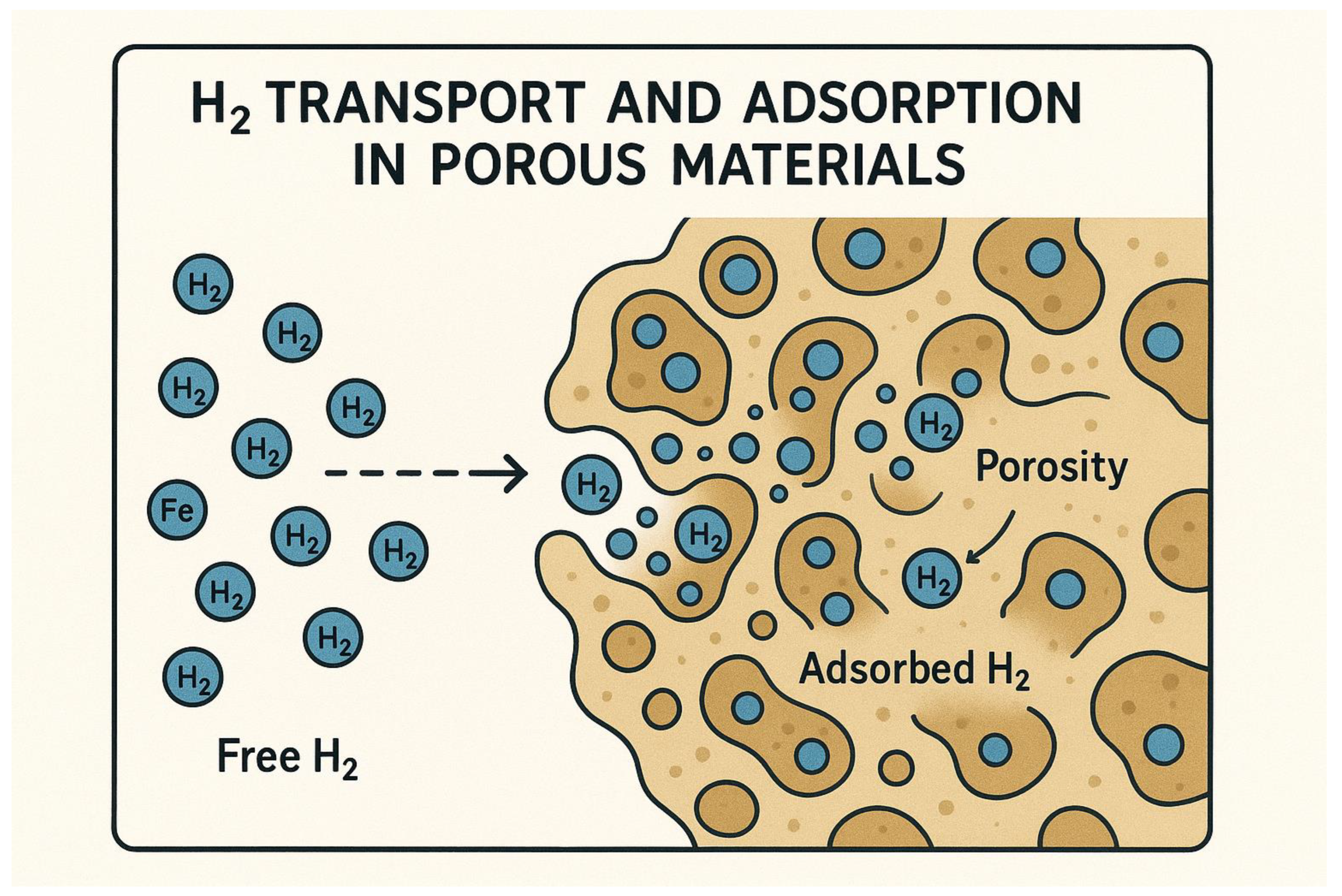
The process of hydrogen adsorption in porous materials entails the diffusion of free H₂ molecules into the pore network, where they interact with the internal surfaces. This interaction leads to the adherence of H₂ molecules to the pore walls through physisorption forces, as depicted in the illustration. The high surface area of the porous structure enhances the adsorption capacity. Various factors such as temperature, pressure, and material properties play a role in influencing this adsorption process.
Figure 1.
H2 transport and adsorption in porous material.
2.1. Problem Statement
The computational domain replicates the experimental configuration reported in [31]. It comprises a cylindrical vessel with a volume of , a radius of , and a height of , enclosed by a -thick steel wall. The entire system is submerged in water maintained at . A small pipe, located at the upper end of the cylinder, functions as the inlet for hydrogen during charging and the outlet during discharging. This pipe has a radius of and a height of . At , a mass of of hydrogen is injected over a period of , defining the loading phase. This is followed by a dormancy period to establish adsorption equilibrium.
2.2. Modified Dubinin-Astakhov (DA) Model for Hydrogen Adsorption
The D-A model describes H₂ adsorption in microporous materials (e.g., activated carbons, MOFs) by correlating the adsorbed amount with temperature and pressure , The principal modification to the original D-A model is that the parameter called characteristic free energy of adsorption, usually symbolized with e, was replaced with the expression [32]:
- : Adsorbed amount (mol/kg)
- : Maximum adsorption capacity (saturation limit)
| Temperature-dependent energy term |
- ∘
- : Material-specific constants (linked to adsorbent-adsorbate interactions)
- ∘
- : Universal gas constant
- Saturation pressure of
- The coefficient is material-dependent and can be adjusted according to the specific MOF under investigation. Notably, has been established as the optimal value for modeling hydrogen adsorption in both MOF-5- and activated carbon, consistent with prior experimental validations.
The values of , , and are summarized in Table 1 for each adsorbent bed employed in this work.
2.3. Governing Equations
The following assumptions were made [33]
- Hydrogen gas is considered as ideal gas;
- The mass source term, , indicates the amount of hydrogen undergoing a phase change, from the adsorbed phase to the bulk phase;
- The average velocity related to the hydrogen flow through the porous medium, , is described by Darcy’s law;
- No volume changes with time, ;
- The temperature difference between the fluid and solid phases of the porous system is negligible, so the local thermal equilibrium approach is adopted for energy equation;
- The flow regime is considered laminar.
Based on these assumptions, the governing equations for the hydrogen adsorption process during charging and dormancy are as follows:
where
The subscript denotes adsorbent particles.
is the permeability and is the mean diameter of adsorbent particles.
The standard thermophysical properties of hydrogen were adopted in this study, specifically: (ie: ).
The corresponding material properties of the adsorbent are summarized in Table 2
2.4. Initial and Boundary Conditions
The initial and boundary conditions are determined by the physical constraints of the system and the specific conditions of the experiment. These conditions are crucial for the accurate representation of the studied phenomenon and are inherent to the resolution of the system of equations {(2. 1)-(2. 4)}. The applied boundary conditions are illustrated in Figure 2.
Experimental studies aimed at setting the hydrogen injection velocity or flow rate have shown that precise control remains challenging, as reflected in the complexity of the flow rate expressions. Moreover, the pressure profile during injection is consistently observed to be linear. Based on these observations, the mass flow rate of injection is defined according to the following equation (2. 11):
where is the total mass of injected hydrogen and is the injection duration. This approach is both practical and logical, as it ensures a controlled and uniform injection process that aligns with observed pressure trends. Moreover, it represents a methodological contribution of this study to the field of hydrogen adsorption, providing a simplified yet effective way to define injection conditions for reproducible and comparable results.
3. Numerical Method, Grid Invariance and Validation
3.1. Numerical Method
The coupled partial differential equations governing hydrogen adsorption were solved using the Finite Element Method (FEM) with specialized discretization schemes. Temperature was approximated using linear Lagrange elements (), while quadratic elements () were employed for pressure discretization to better capture its sharper gradients. The global system was solved using a scaled approach with a tolerance factor of 0.1 for convergence criteria. Time integration was performed via the Backward Differentiation Formula (BDF) method with free order selection, allowing adaptive temporal resolution. A fully coupled Newton-Raphson scheme was implemented with a constant damping factor of to ensure robust convergence. The Jacobian matrix was updated at each timestep to maintain numerical accuracy throughout the transient solution. The resulting linear systems were handled by the MUMPS (MUltifrontal Massively Parallel Sparse) direct solver, chosen for its stability with ill-conditioned systems typical of adsorption problems. Initial conditions were implemented as nodal values corresponding to the pre-adsorption state , while boundary conditions included: (1) Dirichlet conditions for hydrogen supply, (2) Neumann flux conditions for temperature ,, and (3) symmetry conditions where applicable. This numerical framework successfully captured the strong thermo-physical coupling between the adsorbed phase (described by the modified Sips isotherm) and free gas dynamics while maintaining mass and energy balance.
3.2. Grid Invariance and Validation
The numerical model of hydrogen adsorption was rigorously validated against experimental data from Xiao et al (2013) [34]. Six thermocouples were placed along the axisymmetric axis , with two additional thermocouples positioned at the wall and midway between the axis and the wall to monitor the temporal evolution of temperature. With the exception of the point nearest the inlet (), the five remaining points exhibit identical temperature profiles. For this reason, only three measurement locations were selected: , and . Including mean system pressure and temperature , adsorbed mass values , and free hydrogen gas mass . The experimental conditions are presented in the Table 3. since the work focuses mainly on the mass of H2 adsorbed, only the injection and dormancy stages will be considered.
Table 4 presents a quantitative comparison between the experimental data and simulation results for key parameters of the adsorption process. The root mean square error (RMSE), mean absolute percentage error (MAPE), and the maximum relative error were used as indicators of model accuracy.
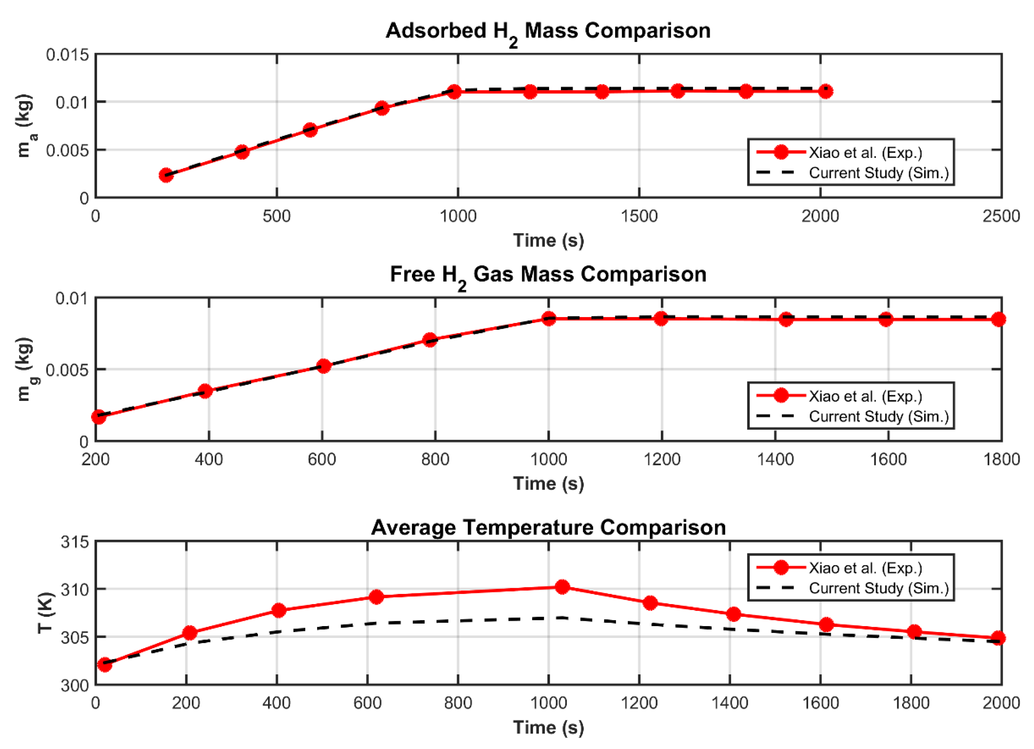
For the adsorbed hydrogen mass , the model shows strong agreement with experiments, with an RMSE of , a MAPE of , and a maximum relative error of Similarly, the free gas mass was well predicted, although slightly higher deviations were noted (MAPE of , max error ).
The average temperature and wall temperature were both accurately captured, with RMSE values of and , and extremely low MAPE values ( and , respectively). The pressure () predictions were also reliable, with a MAPE of 2.34% and a maximum error of 4.42%.
As for the local temperatures at two selected points, and , the model yielded RMSE values of and , and MAPE values of and , respectively, indicating slightly larger but still acceptable discrepancies, particularly at .
Overall, for a study aimed at evaluating global quantities such as , , and , the agreement between the model and experimental results is satisfactory. The discrepancies observed in local temperature values can be attributed to the simplified velocity model adopted, specifically the use of Darcy’s law for flow prediction in the porous medium.
Overall, the results confirm the robustness of the CFD model in reproducing the experimental behavior across thermal, mass, and pressure variables, validating its suitability for further optimization and design analyses.
Figure 3.
Model validation (Temperature field and pressure).
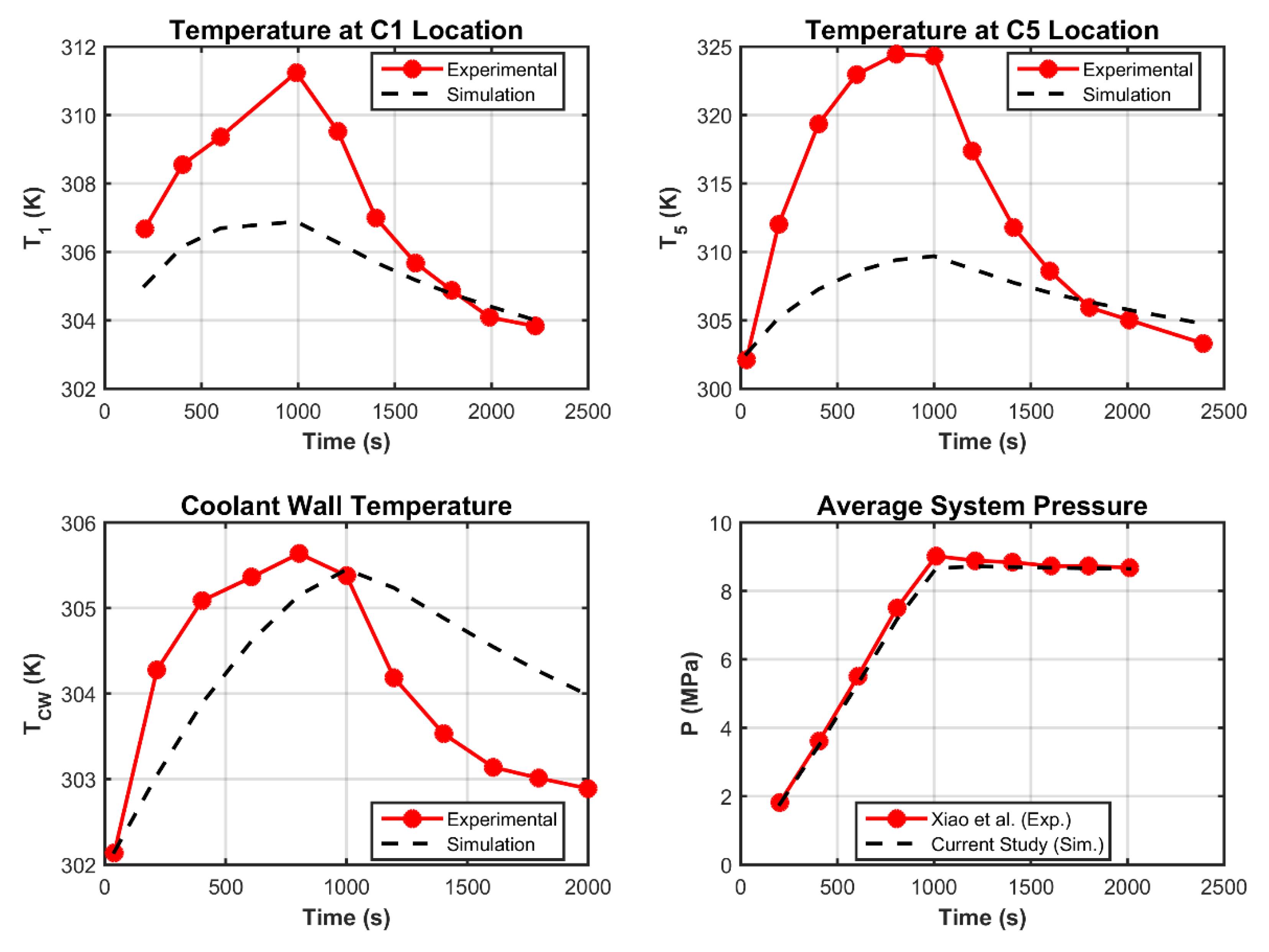
Figure 4.
Model validation (adsorbed and free H2 and Average temperature).
4. Parametric Study
4.1. Effect of Material Properties
Simulation results for H₂ storage using two MOF-5 configurations (powdered and compacted forms) are presented herein, with material characteristics provided in Table 2. Consistent with the activated carbon trials, identical boundary conditions were applied. The time-dependent profiles of system pressure and adsorbed H₂ mass appear in Figure 5 and Figure 6.
The results demonstrate that MOF-5_C achieves the highest H₂ uptake (12 g) while operating at the lowest equilibrium pressure (7 MPa), outperforming both MOF-5_P and AC . This superior performance stems from MOF-5_C’s optimized pore hierarchy, which balances high capacity with efficient mass transport, unlike MOF-5_P, where kinetic limitations arise from particle diffusion resistance. Notably, MOF-5_C’s 20% higher capacity than MOF-5_P and 40% lower pressure requirement than AC challenge conventional assumptions favoring powdered adsorbents. The compacted MOF-5’s structural integrity also offers practical advantages, including reduced energy penalties for compression (~25% savings vs. MOF-5_P) and mitigated particle fluidization risks, critical for industrial applications. These findings position MOF-5_C as the optimal candidate for systems prioritizing volumetric efficiency.
4.2. Effect of “Temperature and Flow Rate” Injection
The superior performance demonstrated in 4.1 motivated the selection of MOF-55 C for systematic optimization of hydrogen adsorption through parametric variation of injection conditions targeting maximal H₂ uptake.
The results are summarized in Table 5. The data reveal that adsorption capacity remains relatively stable () across all tested conditions, with maximal value attributed to couple . Indicating limited sensitivity to and variations within these ranges. However, subtle trends emerge: (1) shorter injection times paired with lower temperatures tend to marginally enhance adsorption ), while (2) longer durations at higher temperatures also achieve comparable performance . Notably, the weak correlation between and operational parameters suggests that MOF-5C’s adsorption is predominantly governed by intrinsic material properties (e.g., pore structure, surface chemistry) rather than injection conditions in these ranges. For practical applications, this implies flexibility in system design- e.g., prioritizing faster cycles at ambient temperatures without significant capacity loss. Further optimization should focus on material modification (e.g., doping, activation) rather than operational parameter tuning alone.
5. Conclusions and Perspectives for Future Work
A CFD model of hydrogen adsorption in porous materials is presented. It is based on the conservation equations (mass, momentum, and energy) coupled with a modified Dubinin–Astakhov model to describe adsorption kinetics. The system was solved using the finite element method. Model validation showed good agreement between simulation results and experimental data. The optimization phase focused on selecting suitable adsorbent materials and identifying the optimal injection conditions to ; that maximize the adsorbed hydrogen mass. The obtained results showed that MOF-5_C achieves the highest H₂ uptake while operating at the lowest equilibrium pressure (7 MPa). yielded the highest adsorbed hydrogen mass, reinforcing previous studies that recommend conducting the adsorption process at low temperatures. This result confirms the strong influence of thermal conditions on adsorption performance and supports the strategic design of operating parameters to enhance storage efficiency.
MOF-5 c safety, and operational cost reduction, though further research is needed to validate long-term cycling stability and scale-up feasibility. For future work, exploring binder-enhanced MOF-5_C formulations and hybrid MOF-5-AC systems could unlock additional performance gains.
Nomenclature
| specific heat capacity | |
| particle diameter of adsorbent | |
| heat transfer coefficient | |
| thermal conductivity | |
| Molecular mass of hydrogen | |
| mass of adsorbed phase hydrogen | |
| mass of gas phase hydrogen | |
| total mass of hydrogen in tank | |
| absolute adsorption amount per unit adsorbent | |
| limit adsorption amount per unit adsorbent | |
| pressure | |
| limited pressure | |
| adsorption heat | |
| universal gas constant | |
| rate, of hydrogen transfer from gas phase to adsorbed phase | |
| temperature | |
| Darcy velocity vector | |
| isosteric heat of adsorption | |
| Greek symbols | |
| enthalpic factor | |
| entropic factor | |
| density | |
| permeability of porous material | |
| dynamic viscosity | |
| bed porosity | |
| Subscript | |
| a | adsorbent |
| ext | exterior or ambient |
| int | initial |
| inj | injection |
| eff | effective |
| p | particles |
| g | gas phase |
References
- A.Z. Arsad, M.A. Hannan, Ali Q. Al-Shetwi, R.A. Begum, M.J. Hossain, Pin Jern Ker, TM Indra Mahlia, Hydrogen electrolyser technologies and their modelling for sustainable energy production: A comprehensive review and suggestions, International Journal of Hydrogen Energy, Volume 48, Issue 72, 2023, Pages 27841-27871, ISSN 0360-3199. [CrossRef]
- Hydrogen liquefaction: a review of the fundamental physics, engineering practice and future opportunities Saif ZS. Al Ghafri, Stephanie Munro, Umberto Cardella, Thomas Funke, William Notardonato, J. P. Martin Trusler, Jacob Leachman, Roland Span, Shoji Kamiya, Garth Pearce, Adam Swanger, Elma Dorador Rodriguez, Paul Bajada, Fuyu Jiao, Kun Peng, Arman Siahvashi, Michael L. Johns and Eric F. May Energy & environmental science 15 (7), 2690-2731. [CrossRef]
- Ayoub Aitakka Nalla, Mourad Nachtane, Xiaobin Gu, Mustapha El Alami, Ayoub Gounni, Advances in numerical modeling and experimental insights for hydrogen storage systems: A comprehensive and critical review, Journal of Energy Storage, Volume 128, 2025, 117206, ISSN 2352-152X. [CrossRef]
- Farshid Mahmoodi, Rahbar Rahimi, Experimental and numerical investigating a new configured thermal coupling between metal hydride tank and PEM fuel cell using heat pipes, Applied Thermal Engineering, Volume 178, 2020, 115490, ISSN 1359-4311. [CrossRef]
- Briki, C.; Dunikov, D.; Almoneef, M.M.; Romanov, I.; Kazakov, A.; Mbarek, M.; Abdelmajid, J. Experimental and Theoretical Studies of Hydrogen Storage in LaNi4.4Al0.3Fe0.3 Hydride Bed. Materials 2023, 16, 5425. [CrossRef]
- Rafik Elkhatib, Hasna Louahlia, Metal hydride cylindrical tank for energy hydrogen storage: Experimental and computational modeling investigations, Applied Thermal Engineering, Volume 230, Part A, 2023, 120756, ISSN 1359-4311. [CrossRef]
- Safia Harrat, Chaker Briki, Mounir Sahli, Abdelhakim Settar, Khaled Chetehouna, Abdelmajid Jemni, Experimental investigation of the hydrogen storage capacity in LaNi3.6Al0.4Mn0.3Co0.7 alloy, International Journal of Hydrogen Energy, Volume 77, 2024, Pages 33-39, ISSN 0360-3199. [CrossRef]
- Wang C-S, Brinkerhoff J. Low-cost lumped parameter modelling of hydrogen storage in solid-state materials. Energy Convers Manag 2022;251:115005. [CrossRef]
- Jinsheng Xiao, Qian Li, Daniel Cossement, Pierre Bénard, Richard Chahine, Lumped parameter simulation for charge-discharge cycle of cryo-adsorptive hydrogen storage system, International Journal of Hydrogen Energy, Volume 37, Issue 18, 2012, Pages 13400-13408, ISSN 0360-3199. [CrossRef]
- Jinsheng Xiao, Min Hu, Daniel Cossement, Pierre Bénard, Richard Chahine, Finite element simulation for charge–discharge cycle of cryo-adsorptive hydrogen storage on activated carbon, International Journal of Hydrogen Energy, Volume 37, Issue 17, 2012, Pages 12947-12959, ISSN 0360-3199. [CrossRef]
- Jinsheng Xiao, Jijuan Wang, Daniel Cossement, Pierre Bénard, Richard Chahine, Finite element model for charge and discharge cycle of activated carbon hydrogen storage, International Journal of Hydrogen Energy, Volume 37, Issue 1, 2012, Pages 802-810, ISSN 0360-3199. [CrossRef]
- Jinsheng Xiao, Rong Peng, Daniel Cossement, Pierre Bénard, Richard Chahine, CFD model for charge and discharge cycle of adsorptive hydrogen storage on activated carbon, International Journal of Hydrogen Energy, Volume 38, Issue 3, 2013, Pages 1450-1459, ISSN 0360-3199. [CrossRef]
- Jinsheng Xiao, Rong Peng, Daniel Cossement, Pierre Bénard, Richard Chahine, Heat and mass transfer and fluid flow in cryo-adsorptive hydrogen storage system, International Journal of Hydrogen Energy, Volume 38, Issue 25, 2013, Pages 10871-10879, ISSN 0360-3199. [CrossRef]
- J. Yao, et al., A continuous hydrogen absorption/desorption model for metal hydride reactor coupled with PCM as heat management and its application in the fuel cell power system, Int. J. Hydrog. Energy 45 (52) (Oct. 2020) 28087-28099. [CrossRef]
- B. Arslan, M. Ilbas, S. Celik, Experimental analysis of hydrogen storage performance of a LaNi5-H2 reactor with phase change materials, Int. J. Hydrog. Energy 48 (15) (2023) 6010-6022. [CrossRef]
- Yang Ye, Jing Ding, Weilong Wang, Jinyue Yan, The storage performance of metal hydride hydrogen storage tanks with reaction heat recovery by phase change materials, Applied Energy, Volume 299, 2021, 117255, ISSN 0306-2619. [CrossRef]
- Atef Chibani, Chahrazed Boucetta, Mohammed Amin Nassim Haddad, Slimane Merouani, Samir Adjel, Safia Merabet, Houssem Laidoudi, Cherif Bougriou, Effect of fin material type and reactor inclination angle on hydrogen adsorption process in large-scale activated carbon-based heat storage system, Journal of Energy Storage, Volume 98, Part B, 2024, 113091, ISSN 2352-152X. [CrossRef]
- Zelenak V, Saldan I. Factors affecting hydrogen adsorption in metal-organic frameworks: a short review. Nanomaterials 2021;11(7):1638. [CrossRef]
- Chuchuan Peng, Rui Long, Zhichun Liu, Wei Liu, Improving adsorption hydrogen storage performance via triply periodic minimal surface structures with uniform and gradient porosities, International Journal of Hydrogen Energy, Volume 53, 2024, Pages 422-433, ISSN 0360-3199. [CrossRef]
- Jiahao Wang, Daniele Melideo, Lorenzo Ferrari, Paolo Taddei Pardelli, Umberto Desideri, Study on the influence echanism of fin structure on the filling performance of cold adsorption hydrogen storage tank, International Journal of Hydrogen Energy, Volume 94, 2024, Pages 897-911, ISSN 0360-3199. [CrossRef]
- Anurag Singh, M.P. Maiya, S. Srinivasa Murthy, Effects of heat exchanger design on the performance of a solid state hydrogen storage device, International Journal of Hydrogen Energy, Volume 40, Issue 31, 2015, Pages 9733-9746, ISSN 0360-3199. [CrossRef]
- Jiahao Wang, Daniele Melideo, Lorenzo Ferrari, Paolo Taddei Pardelli, Umberto Desideri, Integrated targeted pre-cooling tubes and fins for enhanced hydrogen adsorption in activated carbon storage tank, International Journal of Hydrogen Energy, Volume 146, 2025, 149942, ISSN 0360-3199. [CrossRef]
- Xuan Huang, Suke Jin, Meng Yu, Yang Li, Ming Li, Jianye Chen, Numerical studies of a new device for a cryo-dsorption hydrogen storage system, International Journal of Hydrogen Energy, Volume 82, 2024, Pages 1051-1059, ISSN 0360-3199. [CrossRef]
- Jiahao Wang, Daniele Melideo, Lorenzo Ferrari, Paolo Taddei Pardelli, Umberto Desideri, Study on the influence mechanism of fin structure on the filling performance of cold adsorption hydrogen storage tank, International Journal of Hydrogen Energy, Volume 94, 2024, Pages 897-911, ISSN 0360-3199. [CrossRef]
- Jiahao Wang, Daniele Melideo, Lorenzo Ferrari, Paolo Taddei Pardelli, Umberto Desideri, Integrated targeted pre-cooling tubes and fins for enhanced hydrogen adsorption in activated carbon storage tank, International Journal of Hydrogen Energy, Volume 146, 2025, 149942, ISSN 0360-3199. [CrossRef]
- Hind Jihad Kadhim Shabbani, Ammar Ali Abd, Masad Mezher Hasan, Zuchra Helwani, Jinsoo Kim, Mohd Roslee Othman, Effect of thermal dynamics and column geometry of pressure swing adsorption on hydrogen production from natural gas reforming, Gas Science and Engineering, Volume 116, 2023, 205047, ISSN 2949-9089. [CrossRef]
- Chuchuan Peng, Rui Long, Zhichun Liu, Wei Liu, Improving adsorption hydrogen storage performance via triply periodic minimal surface structures with uniform and gradient porosities, International Journal of Hydrogen Energy, Volume 53, 2024, Pages 422-433, ISSN 0360-3199. [CrossRef]
- Lijin Chen, Valeska P. Ting, Yuxuan Zhang, Shuai Deng, Shuangjun Li, Zhenyuan Yin, Fei Wang, Xiaolin Wang, Modeling adsorption-based hydrogen storage in nanoporous activated carbon beds at moderate temperature and pressure, International Journal of Hydrogen Energy, Volume 122, 2025, Pages 159-179, ISSN 0360-3199. [CrossRef]
- Daniele Melideo, Lorenzo Ferrari, Paolo Taddei Pardelli, CFD simulation of hydrogen storage: Adsorption dynamics and thermal management in cryogenic tanks, International Journal of Hydrogen Energy, 2025, 149261, ISSN 0360-3199. [CrossRef]
- Georg Klepp, Modelling activated carbon hydrogen storage tanks using machine learning models, Energy, Volume 306, 2024, 132318, ISSN 0360-5442. [CrossRef]
- Richard MA, Cossement D, Chandonia PA, Chahine R, MoriD, Hirose K. Preliminary evaluation of the performance of an adsorption-based hydrogen storage system. AIChE 2009; 55: 2985e96. [CrossRef]
- Richard MA, Bénard P, Chahine R. Gas adsorption process inactivated carbon over a wide temperature range above the critical point. Part 1: modified Dubinin-Astakhov model. Adsorption 2009; 15:43-51. [CrossRef]
- V. Nicolas, G. Sdanghi, K. Mozet, S. Schaefer, G. Maranzana, A. Celzard, V. Fierro, Numerical simulation of thermally driven hydrogen compressor as a performance optimization tool, Applied Energy, Volume 323, 2022, 119628, ISSN 0306-2619. [CrossRef]
- Jinsheng Xiao, Min Hu, Pierre Bénard, Richard Chahine, Simulation of hydrogen storage tank packed with metal organic framework, International Journal of Hydrogen Energy, Volume 38, Issue 29, 2013, Pages 13000-13010, ISSN 0360-3199. [CrossRef]
| 1 | Volume of porous media |
| 2 | Root Mean Square Error |
| 3 | Mean Absolute Percentage Error |
Figure 2.
Experimental locations and boundary conditions associated to the system of equations.
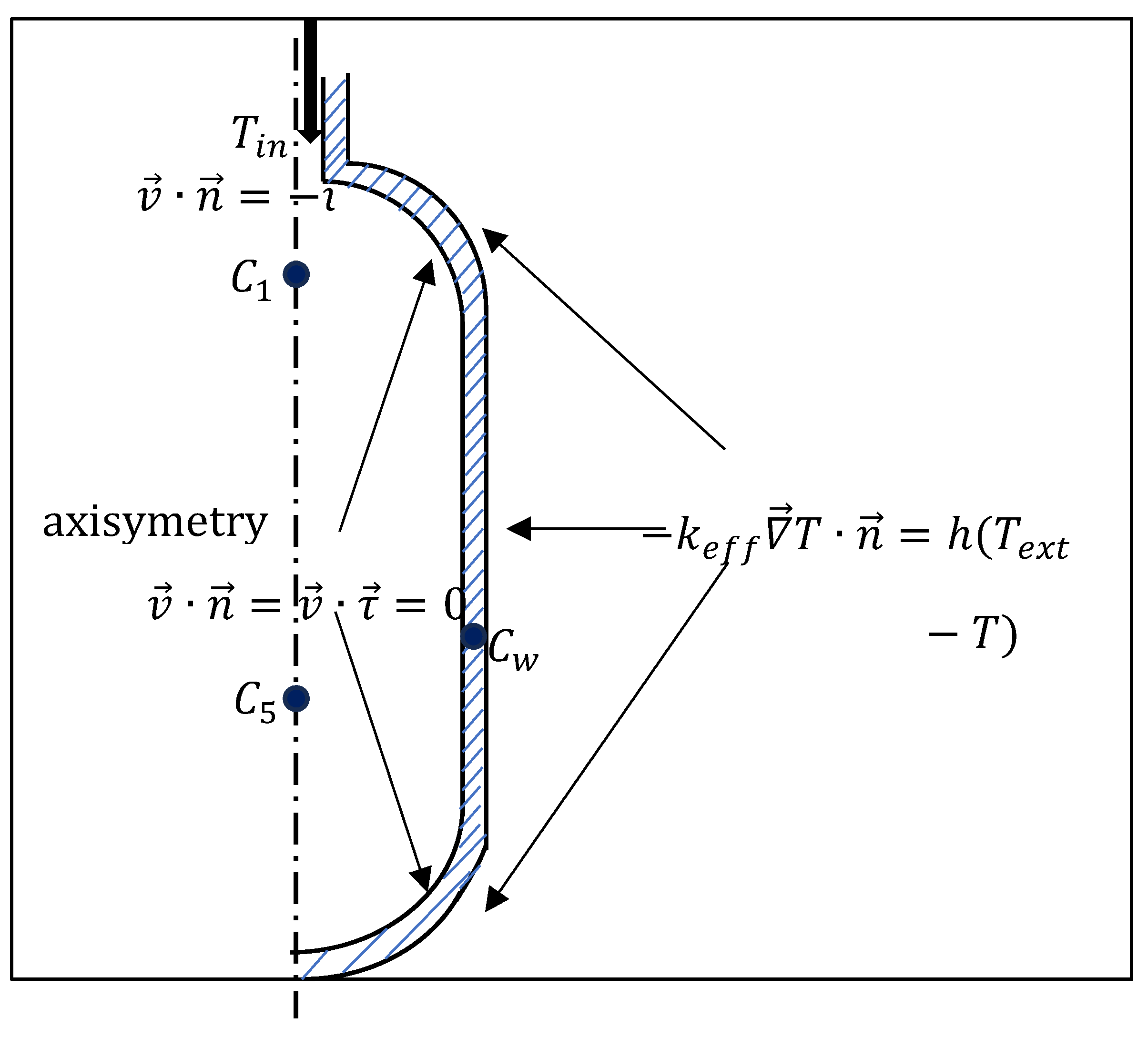
Figure 5.
H2 mass adsorbed for compact and powder MOF-5 and carbon.
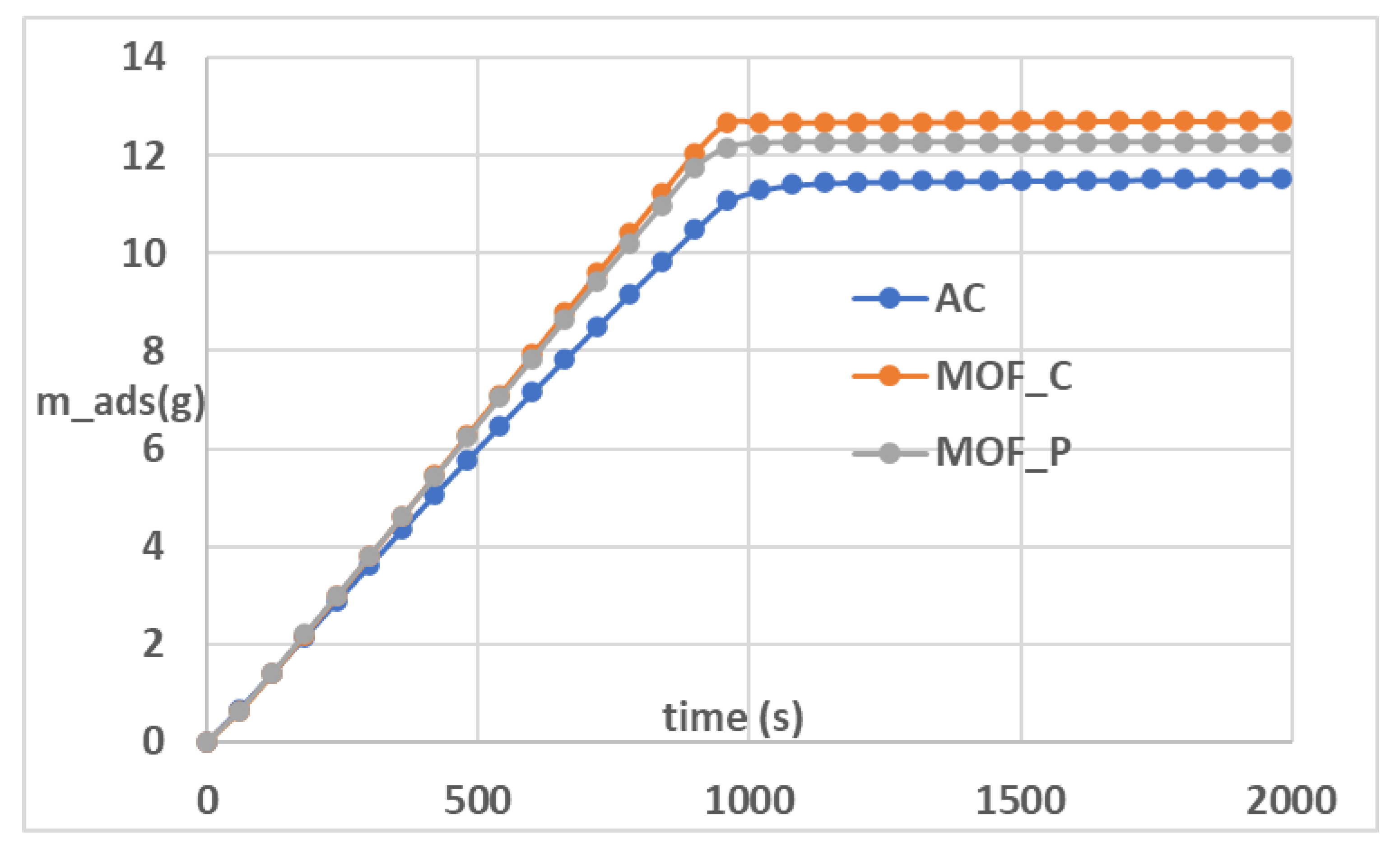
Figure 6.
Pressure profile comparison between compact and powder MOF-5 and acrbon.
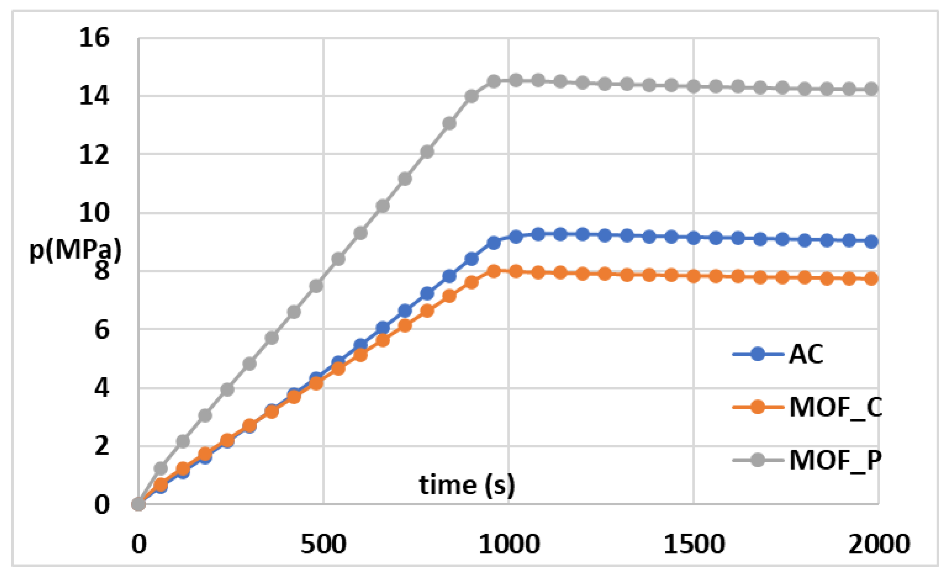

Table 1.
Dubinin-Astakov model parameters.
| Adsorbents | ||||
|---|---|---|---|---|
| Activated carbon (AC) | ||||
| Powder MOF-5 | ||||
| Compact MOF-5 |
Table 2.
Material properties of adsorbents.
| Properties | Activated carbon | Powder MOF-5 | Compact MOF-5 |
| Particle density | |||
| Specific heat | |||
| Conductivity | |||
| Bed porosity | |||
| Paricle diameter |
Table 3.
Experimental conditions of the process.
| Parameter | Value/Description |
| Initial temperature (T₀) | 302 K |
| Total mass of injection | 19.5 g |
| Ambient temperature Text | 302 K |
| Injection time | 953 s |
| Wall heat transfer coefficient | 36 W/m/K |
Table 4.
Quantitative comparison between experimental and simulated results.
| Parameter | RMSE2 | MAPE3 | Maximum relative error |
| 2.4 10⁻⁴ | 2.16% | 3.24% | |
| 1.3 10⁻⁴ | 2.25% | 7.58% | |
| 1.82 | 0.15% | 0.10% | |
| 0.19 | 2.34% | 4.42% | |
| 2.174 | 0.54% | 1.4% | |
| 8.83 | 2.09% | 4.63% | |
| 1.019 | 0.30% | 0.46% |
Table 5.
Mass adsorbed of hydrogen for different temperature and time injection.
| 273 | 200 | 0.012432268 |
| 273 | 400 | 0.012307034 |
| 273 | 600 | 0.012111843 |
| 273 | 800 | 0.012433435 |
| 273 | 1000 | 0.012316264 |
| 283 | 200 | 0.012410988 |
| 283 | 400 | 0.01228127 |
| 283 | 600 | 0.012130479 |
| 283 | 800 | 0.012249503 |
| 283 | 1000 | 0.012319771 |
| 293 | 200 | 0.012124952 |
| 293 | 400 | 0.012293844 |
| 293 | 600 | 0.012233828 |
| 293 | 800 | 0.012309072 |
| 293 | 1000 | 0.012339576 |
| 303 | 200 | 0.012392542 |
| 303 | 400 | 0.012196179 |
| 303 | 600 | 0.012094533 |
| 303 | 800 | 0.012031741 |
| 303 | 1000 | 0.012418507 |
| 313 | 200 | 0.012078094 |
| 313 | 400 | 0.012354711 |
| 313 | 600 | 0.012225714 |
| 313 | 800 | 0.012286743 |
| 313 | 1000 | 0.012346961 |
Disclaimer/Publisher’s Note: The statements, opinions and data contained in all publications are solely those of the individual author(s) and contributor(s) and not of MDPI and/or the editor(s). MDPI and/or the editor(s) disclaim responsibility for any injury to people or property resulting from any ideas, methods, instructions or products referred to in the content. |
© 2025 by the authors. Licensee MDPI, Basel, Switzerland. This article is an open access article distributed under the terms and conditions of the Creative Commons Attribution (CC BY) license (http://creativecommons.org/licenses/by/4.0/).
Copyright: This open access article is published under a Creative Commons CC BY 4.0 license, which permit the free download, distribution, and reuse, provided that the author and preprint are cited in any reuse.


