
Submitted:
09 April 2025
Posted:
10 April 2025
You are already at the latest version
Abstract
This research models a 20 MW PEM hydrogen plant. PEM units operate in the range of 60 to 80 ⁰C based on their locations and sizes. This study aims to recover the waste heat from modules to enhance the efficiency of the plant. In order to recover the heat, two systems are implemented: (a) recovering the waste heat from each PEM module and (b) recovering the heat from hot water for producing electricity using an organic refrigerant cycle (ORC). The model is made by ASPEN®, and the ORC is optimized using Python. The ORC module is optimized to maximize the produced electricity and enhance the cycle's efficiency. The system is a closed-loop cycle operating at 25 ⁰C and ambient pressure. The 20 MW PEM electrolyzer model produces 363 kg/hr of hydrogen and 2877 kg/hr of oxygen. Based on the higher heating value (HHV) of hydrogen, the plant produces 14302.2 kWh of hydrogen energy equivalent. The ORC is being maximized by increasing the electricity output from the turbine and reducing pump work while maintaining energy conservation and the mass balance. Solving equation 6 resulted in the electricity power output reaching 555.88 kW and the pump power reaching 23.47 kW.
Keywords:
Green hydrogen production
; PEM
; organic refrigerant cycle
; waste heat recovery
1. Introduction
Hydrogen is a fundamental atom in many chemical compounds and processes. It is an intermediate molecule for many processes and an energy carrier stand-alone. In the last two decades, producing reasonably priced hydrogen without emitting tons of emissions has attracted attention among scientists and industry.
There are two main pathways to reform feedstocks to hydrogen: (a) using thermal energy and heating processes, and (b) using electricity to reform the feedstock. Steam methane reforming is the most convenient technology for producing hydrogen, utilizing 800 ⁰C to crack natural gas. Results from research have shown that if electricity is used to reform the feedstock into hydrogen, there is a good opportunity to reduce emissions and be cost-competitive at scale production [1,2,3]. Figure 1 illustrates various hydrogen production pathways.
Finding the fittest to-purpose-cost beneficial with minimum environmental impact for producing hydrogen depends on the geographical location and resources. The proper system can be deployed based on the availability of resources such as water or natural gas. Technologies such as Plasma [3,4], electric heating [5], and electrolyzers [6] utilize electricity to reform the feedstock to hydrogen. This research is focused on proton exchange membrane (PEM) electrolyzers [7] to reform water into hydrogen, facilitating the organic refrigerant cycle (ORC) [8] to enhance the system’s efficiency.
In current systems, the heat generated by modules is released into the air. In fact, if a heat recovery system is utilized, the generated heat can be returned to the system to produce electricity. There is not much literature and studies on heat recovery from PEM for large-scale hydrogen production. Norbet and Assma have done thermo-economic studies of waste heat recovery in PEM using the Rankine cycle utilizing ethane and R1233zd(E) [9]. Els van and his collaborators looked at utilizing heat at a 2.5 MW PEM plant. They recommended expanding the model to a larger scale using industrial data, which this study tried to use [10].
1.1. Water Electrolyzer
There are various electrolyzer systems for producing hydrogen, including alkaline electrolyzers, polymer electrolyte membranes (PEM), solid oxide cells (SCOECs), aion exchange membrane (AEM), supercritical water electrolysis (SWE), high-pressure electrolysis (HPE), high-temperature electrolysis (HTE) [11]. Table 1 briefly compares these technologies.
1.2. Proton Exchange Membrane Electrolyzer
Proton exchange membrane electrolyzers are equipment that utilizes a solid polymer electrolyte to produce hydrogen through the electrolysis of water. The main advantages of using PEM electrolysis are its compact design, high efficiency, high hydrogen rate of production, rapid response to power fractionation, and high hydrogen purity. The main challenges associated with PEM are material costs, water purity sensitivity, and the durability of the membrane and catalysts. PEM electrolysis occurs in three key steps:
(a) Water splits at the anode:
2H2O → 4H++4e-+O2,
(b) proton migrates through the PEM toward the cathode.
(c) the protons (H+) recombine with electrons supplied from the external circuit to form molecular hydrogen gas:
4H++4e→2H2,
The overall reaction:
2H2O → 2H2+O2,
The schematic of PEM electrolysis process is shown in Figure 2
1.3. Organic Refrigerant Cycle
Organic refrigerant cycles (ORC) are thermodynamic processes that use organic working fluids to transfer heat. These cycles are particularly advantageous when dealing with low to moderate-temperature heat sources [14]. ORC operates similarly to the traditional Rankine cycles but uses organic fluids with lower boiling points, such as hydrocarbons or refrigerants, instead of water. ORC can be used in various applications such as waste heat recovery, geothermal power generation, and solar thermal power.
Choosing the appropriate working fluid depends on the application, thermodynamic properties, environmental impacts, safety, and economic concerns. Fluids like R123, R245fa, and R245ca are commonly selected based on their favorable characteristics.
The efficiency of a typical with no heat recovery modules, PEM hydrogen production is in the ranges from 60 to 70% when considering the lower heating value of hydrogen [15]. In this research, a 20 MW plant is modeled to evaluate efficiency after adopting ORC and waste-to-heat modules.
In this design, the extra wasted energy is recovered via ORC to enhance the efficiency of the system. As the efficacy of the PEM module increases, less attention has been focused on the desired heat from the modules. In typical PEM systems, the heat dissipates to the surroundings. In large-scale applications, the amount of wasted heat becomes more viable and cost-effective for recovery and use.
Figure 3 illustrates the organic refrigerant cycle module. The module includes a pump, an evaporator, a turbine, and a condenser. An organic working fluid is heated in a boiler until it is converted to vapor. Then the vapor goes to the turbine, where it is expanded and produces work. After the turbine, the gas is condensed fluid through the pump, which raises the fluid’s pressure, making it ready to enter the boiler again.
1.4. Aim and Novelty
As the PEM system is utilized to produce hydrogen, an excessive amount of heat will be released through the modules. This study aims to capture that heat via ORC and use it to enhance the system’s efficiency. The novelty of this study lies in modeling a 20 MW electrolysis system with ORC. The ORC module is capable of producing electricity from waste heat. Additionally, optimization enhances system efficiency and total efficiency of the ORC system by reducing pump power while increasing turbine power in the refrigerant unit.
2. Methods
The software Aspen Plus® is used to model and simulate 20 MW electrolysis processes with a cooling system for heat recovery modules, and the efficiency is compared with conventional systems. PENG-ROB library is hired as the property method.
The total system efficiency () is calculated by Eq. 4; defined by the total heat transfer from the system (), the total required electricity for hydrogen production (), heat loss from the electrolyzer stack for cooling the hydrogen and oxygen (), electricity requirements for the electrical pump ( and ), and electricity input to the total system (). The total efficiency of the ORC system can be calculated by the difference between the turbine work and pump work, divided by the transferred heat into the system, as shown in Eq 5.
2.1. Technical Analysis
The electrolyzer model is built to analyze 20 MW utilizing ORC heat recovery modules with conventional systems. Technical analyses aim to investigate the quality and quantity of recoverable waste heat available from the electrolysis process and compare it with previously built systems. In each scenario, the amount of heat waste and, therefore, the efficiency of the system are calculated.
2.2. Model Development
As shown in Figure 4, a 20 MW plant includes waste heat captures, and an ORC module is modeled. The system consists of ten 2 MW PEM modules. A 2 MW module is illustrated in Figure 5. As shown in each 2 MW module, each module includes a PEM module, three heat exchangers, and two separators. The PEM stack is fed with two streams: (a) 2 MW of electricity and (b) water at ambient temperature and pressure conditions (20 ⁰C and 1 bar). Based on experimental results, the operation temperature of PEM is 70 ⁰C at the pressure of 30 bar [16,17]. Inside the PEM stack, the model simulates the electrolysis process shown in equations 1-3, where the water splits into hydrogen and oxygen. The hydrogen and oxygen then separate via a separator. Manufacturers such as FEST GmbH, ITM Power, IMI VIVO, Nel Hydrogen, Simens, Hele Titanium, and many more offer 2 MW PEM electrolyzers.
Table 2 summarizes the operating parameters of the 2 MW PEM electrolyzer and the heating capture system. In this operation, all water runs at ambient pressure and temperature conditions to optimize the energy consumption of cooling systems.
The hydrogen production mass flow rate and output pressure are compared to evaluate the performance of the modeled 2 MW PEM electrolyzer and available PEM electrolyzer benchmarked technologies.
In order to further increase the operation efficiency, water captures heat from each stack and flows out of each module. Then, the total water enters the ORC. R245fa working fluid is utilized to recover heat, which is appropriate for recovering low-temperature heat [18,19]. Another advantage of R245fa is the coolant’s low viscosity, which reduces the pumping power required in the ORC system. The input parameters for ORC are summarized in Table 3.
Water steam of 76.48 ⁰C enters the ORC module from the heat recovery water system, enters the evaporator (EVA), and transfers its heat to the R245fa working fluid. This heat exchange raises the fluid’s temperature, causing its phase change into a vapor. A supercritical temperature of 5 ⁰C is assumed for working fluid after its evaporation. After the heat exchange, the water leaves the evaporator at 41.73 ⁰C. and goes through a turbine. At this stage, electricity will be produced from the turbine coupled with a generator. In the next step, the water will pass through a condenser. The cold water will be pumped back into the evaporator for the next cycle.
The total efficiency of the ORC system can be calculated by the difference between the turbine and pump works, divided by the transferred heat into the system, as shown in Eq.5. The operation condition for the 20 MW plant is summarized in Table 4.
2.3. Maximizing ORC Efficiency
In order to increase the efficiency of the process, the ORC module is optimized to maximize the produced electricity and enhance the cycle’s efficiency. Therefore, the objective function is defined as
where the quality penalty is defined as:
And
The represents the cycle’s work, calculates the turbine work and measures the pump’s work.
For limiting feasible solutions and meeting actual physical properties, the below constraints have been used to avoid any system failures during the process:
Superheat constraint:
Subcooling constraint
Pressure constraints
Net positive suction head (NPSH) constraint
The NPSH is calculated using the blow equations:
To make sure calculations are correct, the overall energy balance for ORC is formulated as below:
The evaporator heat transfer, condenser heat transfer, and recuperator heat transfer using the effectiveness-NTU method are calculated as follows:
The effectiveness-NTU is expressed as below:
LMTD represents the lean mean temperature difference (LMTD) method for heat exchangers:
In the end, the thermal efficiency of the cycle is calculated using equation 21:
3. Results
3.1. Hydrogen Production and Heat Recovery in 20 MW PEM Electrolyzer
The Aspen V14 is used to model a 20 MW hydrogen production plant that utilizes waste heat recovery and ORC to produce electricity. The system is a closed-loop cycle operating at 25 ⁰C and ambient pressure. The 20 MW PEM electrolyzer model produces 363 kg/hr of hydrogen and 2877 kg/hr of oxygen. Based on the higher heating value (HHV) of hydrogen, the plant produces 14302.2 kWh hydrogen energy equivalent. Table 5 represents the results for producing hydrogen and streams for each 2 MW stack.
As a result, each PEM stack rejects 546.36 kW of thermal energy. Therefore, the heat recovery captured from 10 2MW stacks is equal to 5463.65 kW. This means that from the electricity provided to separate hydrogen and oxygen, 5463.65 kW of heat is lost, which is 27.32% of the power input and is available for recovery. The cooling water runs through the plant so as to (a) capture rejected heat from PEM units, (b) cool down the produced hydrogen, and (c) cool down the produced oxygen. Table 6 represents the results for cooling water to each 2 MW PEM electrolyzer.
The cumulative amount of required electricity for producing hydrogen, recovered waste heat from stacks, and heat loss while producing oxygen and hydrogen are calculated. Table 7 provides the summary results.
Figure 6 presents the energy flow within the PEM stacks and demonstrates the energy flow for producing hydrogen. As it is clear, the majority of energy within the system is present in the form of hydrogen. The total electrical system conversion efficiency is 71.41%. By capturing waste heat, the thermal efficiency of the system will increase and therefore the system efficcieny will further enhance. An ORC module is added to the plant so to maintain the 25 ⁰C cooling water recirculating through the plant and producing some electricity from the recovered heat, which is 27.32% of total input energy. In the following sections, the electricity produced and optimizing ORC is explained.
3.2. Organic Refrigerant Cycle
After collecting the waste heat via water from PEM stacks, the temperature of ambient temperature water will reach 76.48 ⁰C, which is the operation temperature of the typical PEM fuel cells. The water enters the ORC module to return to ambient temperature, 25 ⁰C. The water passes through an evaporator to exchange heat with R245fa refrigerant. The refrigerant working fluid passes through the turbine and produces electricity, as Figure 3 shows. The water exits the evaporator and cools down to 25 ⁰C so as to recirculate through the plant. Table 8 presents the results for the ORC module.
As the ORC cools down the water to ambient temperature, the wasted heat is used to produce electricity from phase changes of the working fluid. The summary of results for ORD is presented in Table 9.
3.3. Maximizing ORC Efficiency
The ORC is being maximized by increasing the electricity output from the turbine and reducing pump work while maintaining energy conservation and the mass balance. Solving equation 6 resulted in the electricity power output reaching 555.88 kW and the pump power reaching 23.47 kW. Therefore, the electricity power output increased by 555.88 kW from 169.97 kW. In order to achieve maximum efficiency, the mass flow rate of working fluid, cooling water, and hot water are also optimized. Based on the optimized value, the working fluid and cooling water mass flow rates are 61,200 kg/hr and 1,033,092 kg/hr, respectively. Additionally, this optimization improves the total system efficiency (η), calculated using Eq. 4, from 72.95 to 74.80, and increases the ORC system’s total efficiency from 3.06 to 10.13 based on Eq. 5. Table 10 compares the results before and after optimizing the ORC.
Figure 7 illustrates the pressure enthalpy diagram for the ORC. In this optimization, the efficiency of the turbine and pump is assumed to be 70%, which is a conservative assumption.
4. Discussion
This study aimed to enhance the efficiency of the PEM hydrogen plant by incorporating heat recovery modules into the system. Heat is utilized in two ways throughout the system: (a) the heat recovered from each PEM module and (b) heat recovery from the refrigerant cycle for generating electricity and enhancing the system’s efficiency. Results prove that 5463.65 kW of energy is available to recover from ten 2 MW PEM modules. This heat is recovered through a flow of water. The heated water passes through the ORC module and a turbine unit to heat the working fluid, R245fa, which in turn produces electricity.
Results show that the work done by the turbine is sufficient to provide the energy needed for cooling hydrogen or oxygen water. Comparing results with previous works utilizing ORC [20] shows this system operates at ambient temperature, using cooling fluid water, which is a huge energy cost advantage. Moreover, less water mass flow rate is required to cool down the system.
The ORC module effectively utilizes waste heat from the PEM stacks, reducing water temperature from 76.47 °C to 25 °C, generating 169.97 kW of electricity in its initial configuration. Optimization efforts further enhanced performance, increasing ORC power output to 555.88 kW and improving total system efficiency to 74.80%. These improvements stem from optimizing mass flow rates of both the working fluid and cooling water while maintaining energy conservation principles.
The waste heat recovery system not only enhances efficiency but also supports sustainable energy utilization by reducing the cooling load and repurposing otherwise lost thermal energy. This integration is particularly beneficial for large-scale hydrogen production facilities, where efficiency gains translate to significant cost savings and lower environmental impact. Optimizing the ORC not only reduced the volume of required water for cooling but also increased the net efficiency of the refrigeration cycle.
Author Contributions
Shayan S. Niknezhad: Conceptualization (lead); methodology (equal); software (lead); validation (lead); formal analysis (lead); investigation (lead).; resources (lead); data curation (lead); writing –original draft preparation (lead); writing – review and editing (equal); visualization (equal); supervision (lead); project administration (lead); Forough Moghaddamali: Conceptualization (supporting); methodology (equal); software (supporting); validation (supporting); formal analysis (supporting); (writing –original draft preparation (supporting); writing – review and editing (equal); visualization (equal); Stratos Pistikopoulos: Review and editing.
Funding
This research received no external funding.
Acknowledgments
Thanks to Texas A&M Energy Institute for supporting this research.
Conflicts of Interest
Authors declare no conflicts of interest.
Abbreviations
The following abbreviations are used in this manuscript:
| AEM | Anion exchange membrane |
| HTE | High-temperature electrolysis |
| ORC | Organic refrigerant cycle |
| PEMI | Proton exchange membrane |
| SCOECs | Solid Oxide Electrolyzer Cells |
| SWE | Supercritical water electrolysis |
Symbols
The following symbols are used in this manuscript:
| HHV | Higher heating value |
| MW | Megawatt |
| kW | Kilowatt |
| kg/hr | Kilograms per hour |
| °C | Degrees Celsius |
| bar | Pressure unit |
| η | Efficiency |
| H₂ | Hydrogen |
| O₂ | Oxygen |
| e⁻ | Electron |
| H⁺ | Proton |
| R245fa | Organic refrigerant used in ORC |
| h | Enthalpy |
| Q | Heat transfer |
| W | Work output |
| T | Temperature |
| P | Pressure |
Appendix A
Appendix A.1

Table A1.
Model’s statistics.
| Statistic | |
|---|---|
| Number of variables | 6270 |
| Number of incident variables | 6263 |
| Number of fixed variables | 563 |
| Number of free variables | 5707 |
| Number of equations | 5707 |
| Number of excluded equations | 0 |
| Number of non-zeros | 20563 |
| Number of incidents non-zeros | 19457 |
| Number of incomplete connections | 0 |
References
- Nyangon J, Darekar A. Advancements in hydrogen energy systems: A review of levelized costs, financial incentives and technological innovations. Innovation and Green Development. 2024; 3:100149.
- Wolfram P, Kyle P, Fuhrman J, O’Rourke P, McJeon H. The hydrogen economy can reduce costs of climate change mitigation by up to 22%. One Earth. 2024;7:885-95.
- Niknezhad SS, Staack D, Pistikopoulos EN. Hydrogen Production Plant Via an Intensified Plasma-Based Technology. Available at SSRN 4889037.
- Mizeraczyk J, Jasiński M. Plasma processing methods for hydrogen production. The European Physical Journal Applied Physics. 2016; 75:24702.
- Yang H, Nuran Zaini I, Pan R, Jin Y, Wang Y, Li L, et al. Distributed electrified heating for efficient hydrogen production. Nature Communications. 2024; 15:3868.
- Wappler M, Unguder D, Lu X, Ohlmeyer H, Teschke H, Lueke W. Building the green hydrogen market–Current state and outlook on green hydrogen demand and electrolyzer manufacturing. International Journal of Hydrogen Energy. 2022; 47:33551-70.
- Wang Y, Diaz DFR, Chen KS, Wang Z, Adroher XC. Materials, technological status, and fundamentals of PEM fuel cells–a review. Materials today. 2020; 32:178-203.
- Iglesias Garcia S, Ferreiro Garcia R, Carbia Carril J, Iglesias Garcia D. A review of thermodynamic cycles used in low temperature recovery systems over the last two years. Renewable and Sustainable Energy Reviews. 2018; 81:760-7.
- Lümmen N, Karouach A, Tveitan S. Thermo-economic study of waste heat recovery from condensing steam for hydrogen production by PEM electrolysis. Energy Conversion and Management. 2019; 185:21-34.
- van der Roest E, Bol R, Fens T, van Wijk A. Utilisation of waste heat from PEM electrolysers – Unlocking local optimisation. International Journal of Hydrogen Energy. 2023; 48:27872-91.
- Yang B, Zhang R, Shao Z, Zhang C. The economic analysis for hydrogen production cost towards electrolyzer technologies: current and future competitiveness. International journal of hydrogen energy. 2023; 48:13767-79.
- Sood S, Prakash O, Boukerdja M, Dieulot J-Y, Ould-Bouamama B, Bressel M, et al. Generic Dynamical Model of PEM Electrolyser under Intermittent Sources. Energies. 2020; 13:6556.
- DOE. Fact of the Month August 2018: Global Electrolyzer Sales Reach 100 MW per Year. DOE; 2018.
- Tchanche BF, Lambrinos G, Frangoudakis A, Papadakis G. Low-grade heat conversion into power using organic Rankine cycles–A review of various applications. Renewable and Sustainable Energy Reviews. 2011; 15:3963-79.
- Younas M, Shafique S, Hafeez A, Javed F, Rehman F. An Overview of Hydrogen Production: Current Status, Potential, and Challenges. Fuel. 2022; 316:123317.
- Wang L, Husar A, Zhou T, Liu H. A parametric study of PEM fuel cell performances. International Journal of Hydrogen Energy. 2003; 28:1263-72.
- Nur Ozdemir S, Taymaz I, Okumuş E, Gül Boyacı San F, Akgün F. Experimental investigation on performance evaluation of PEM electrolysis cell by using a Taguchi method. Fuel. 2023; 344:128021.
- Yang J, Ye Z, Yu B, Ouyang H, Chen J. Simultaneous experimental comparison of low-GWP refrigerants as drop-in replacements to R245fa for Organic Rankine cycle application: R1234ze(Z), R1233zd(E), and R1336mzz(E). Energy. 2019; 173:721-31.
- Kajurek J, Rusowicz A, Grzebielec A, Bujalski W, Futyma K, Rudowicz Z. Selection of refrigerants for a modified organic Rankine cycle. Energy. 2019; 168:1-8.
- María Villarreal Vives A, Wang R, Roy S, Smallbone A. Techno-economic analysis of large-scale green hydrogen production and storage. Applied Energy. 2023; 346:121333.
Figure 1.
Hydrogen production pathways.
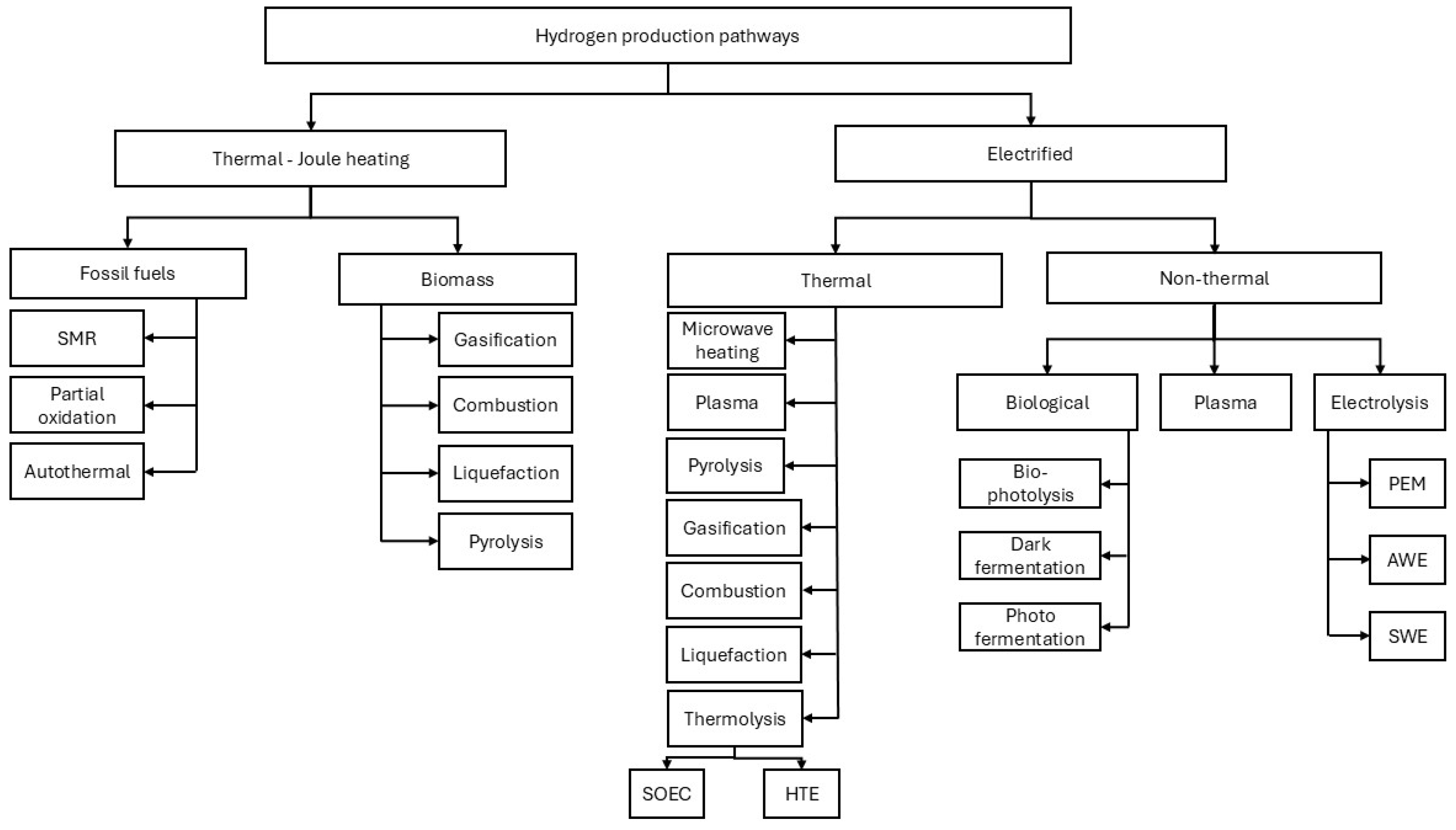
Figure 2.
PEM electrolysis process [13].
Figure 2.
PEM electrolysis process [13].
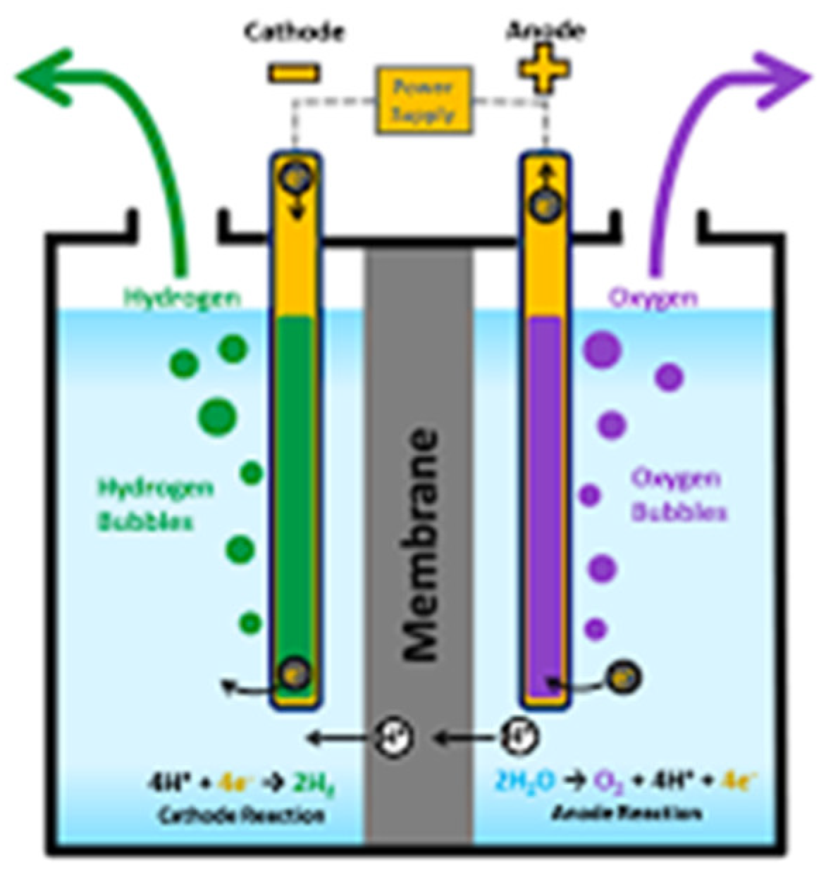
Figure 3.
Organic refrigerant cycle.
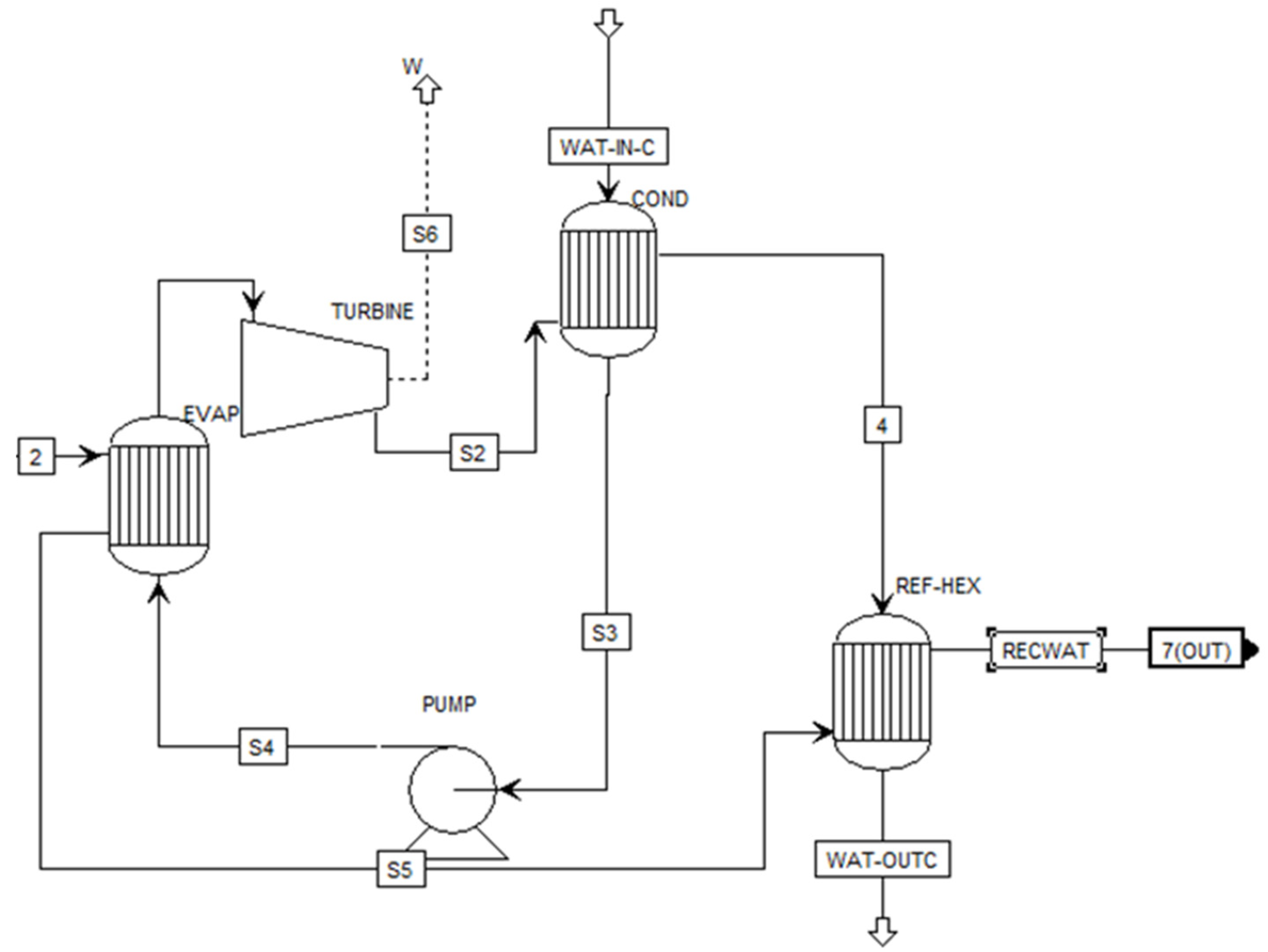
Figure 4.
20 MW PEM hydrogen production with heat recovery and ORC module.
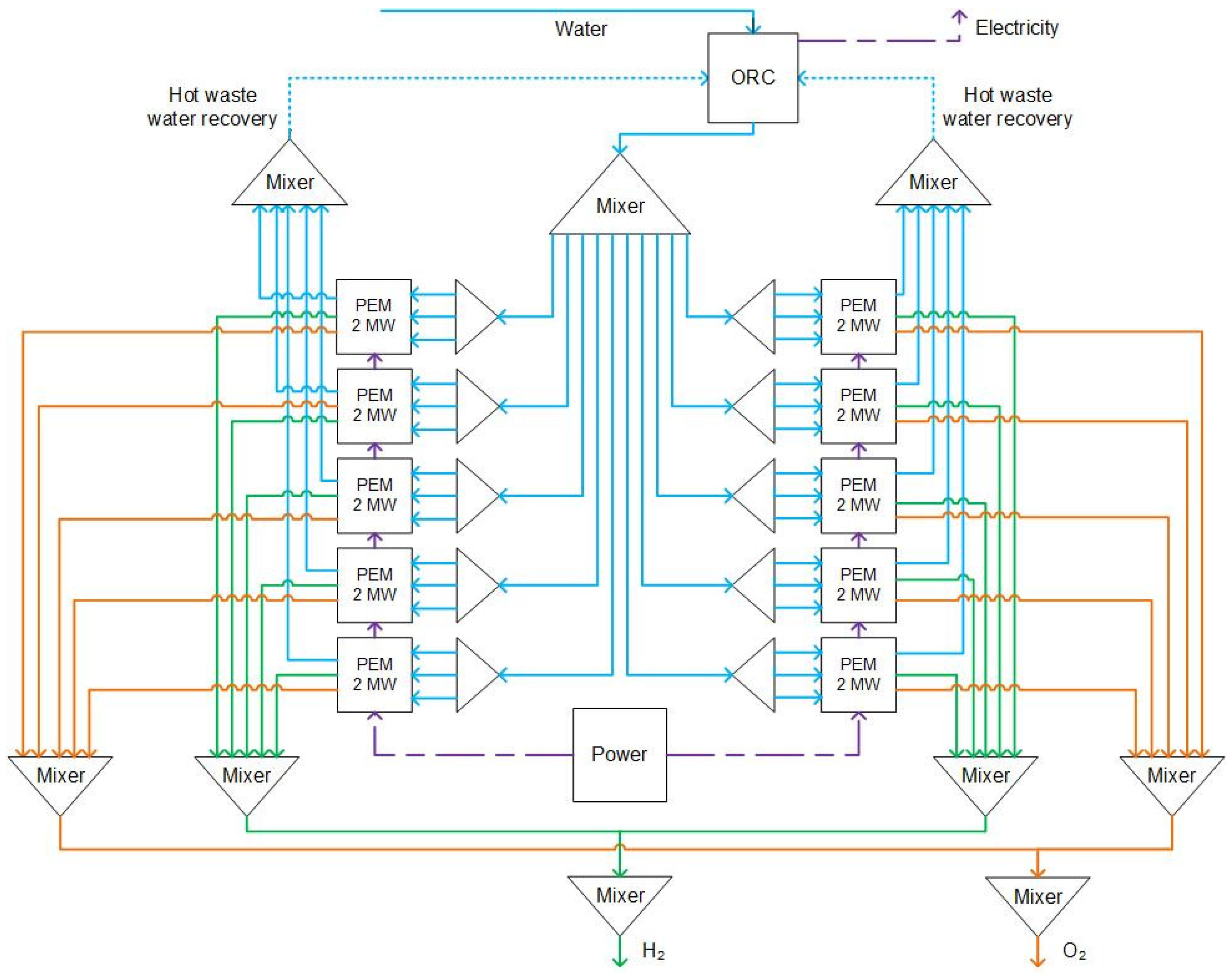
Figure 5.
2 MW PEM module.
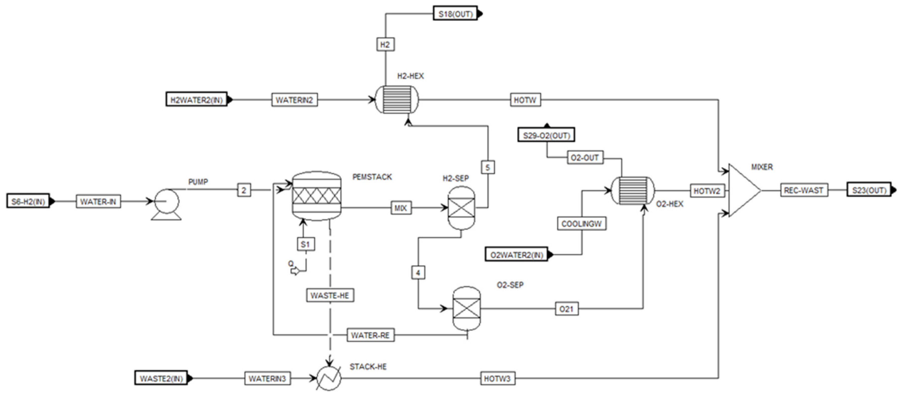
Figure 6.
Sankey diagram of energy flow within the PEM process.
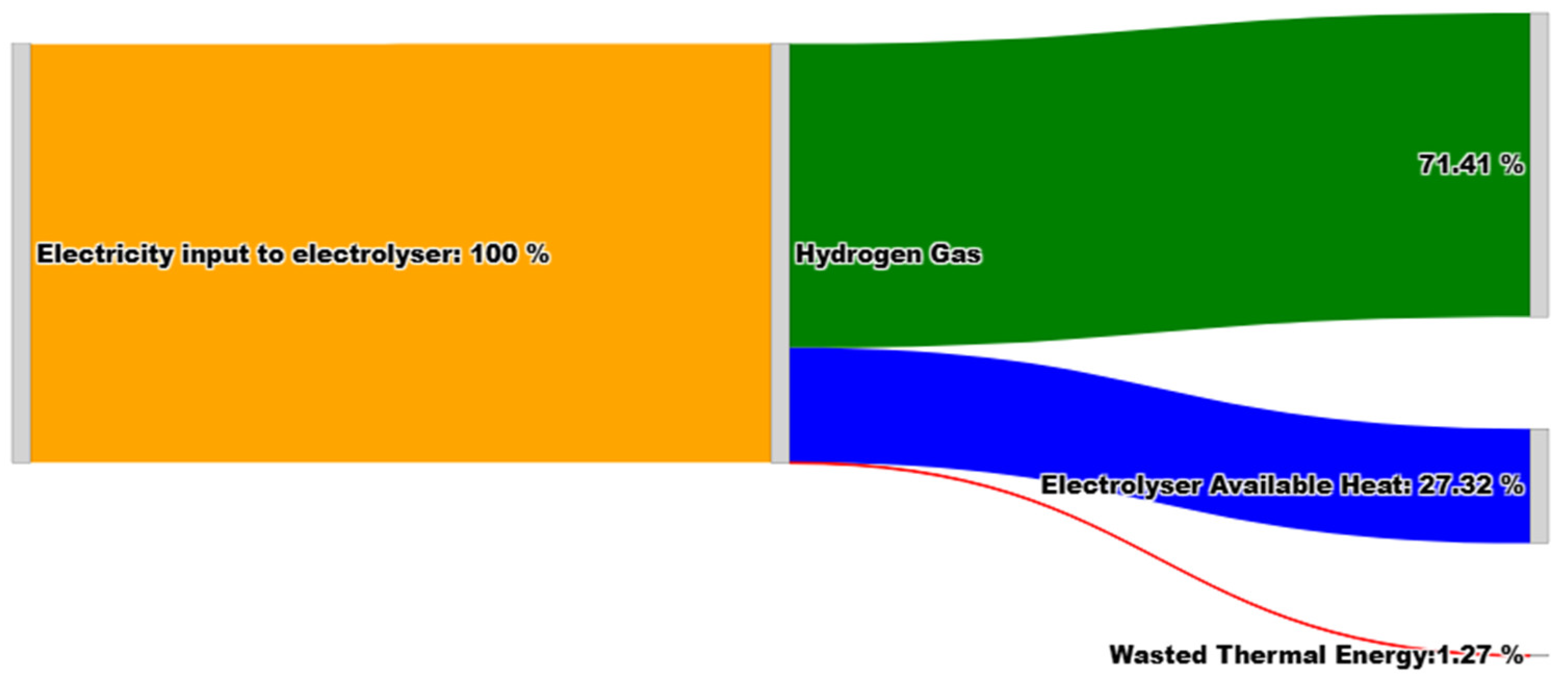
Figure 7.
Pressure-enthalpy diagram for the optimized Organic Rankine Cycle (ORC).
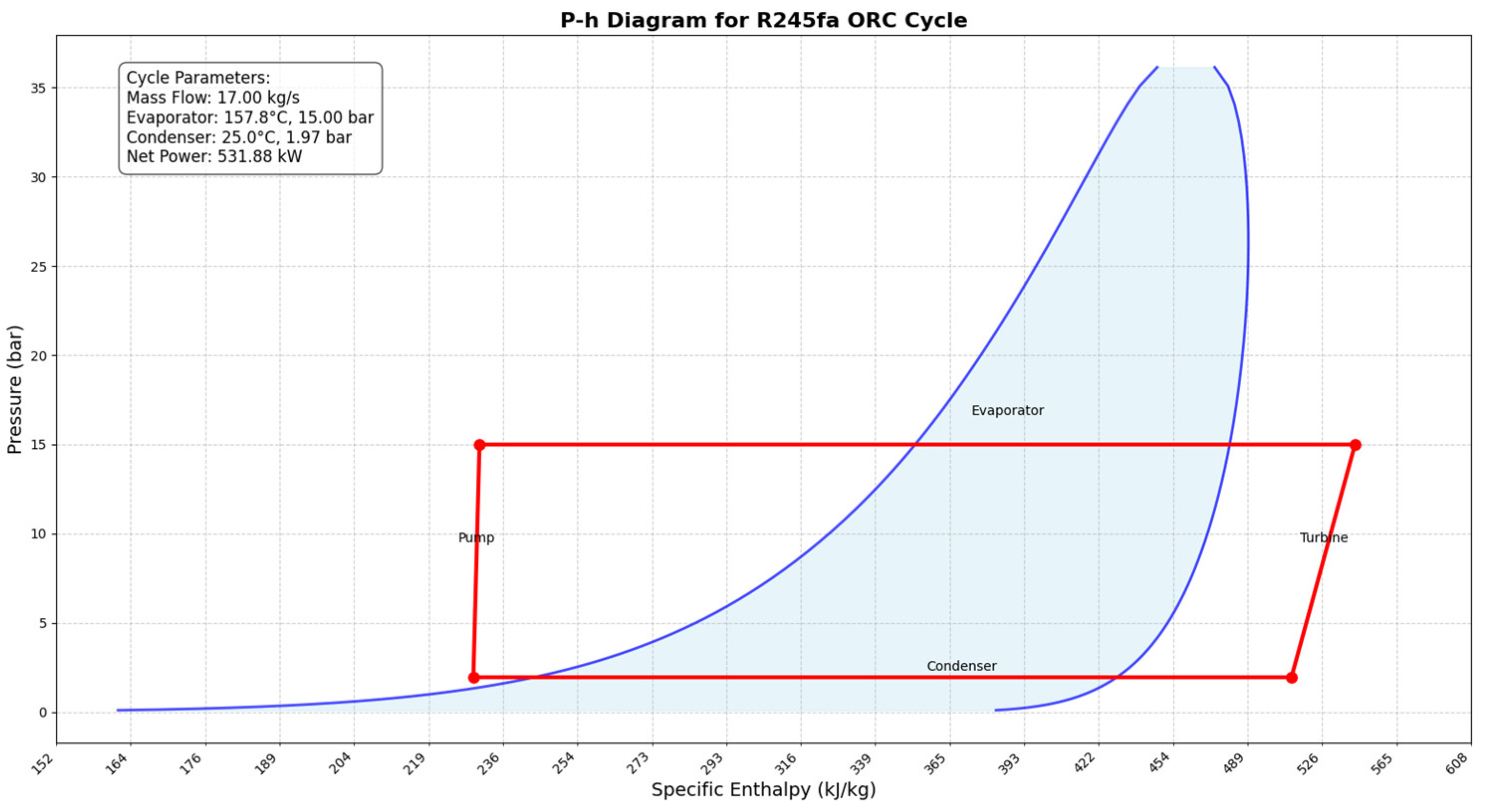
Table 1.
Electrolyzers for producing water technologies.
| Technology | Electrolyte Type | Operating Temperature | Efficiency | Advantages | Challenges |
|---|---|---|---|---|---|
| Alkaline Electrolyzer (AWE) | Liquid alkaline solution (KOH) | 60–90°C | 70–80% | Mature technology, lower capital costs, uses non-precious metal catalysts | Larger physical footprint, slower response to load changes, lower current density |
| Proton Exchange Membrane (PEM) Electrolyzer | Solid polymer membrane | 50–80°C | 60–70% | Compact design, rapid response to power fluctuations, higher current density | Higher capital costs due to the use of precious metal catalysts, sensitive to water impurities |
| Solid Oxide Electrolyzer Cells (SOECs) | Solid ceramic material | 700–1,000°C | Up to 100% (theoretical) | High efficiency due to elevated temperatures, potential for waste heat utilization | High operating temperatures lead to material degradation, currently in developmental stages |
| Anion Exchange Membrane (AEM) Electrolyzer | Anion-exchange membrane | <100°C | Emerging technology | Potential for lower costs using non-precious metal catalysts combines benefits of AWE and PEM | Still under research, durability, and performance need further validation |
| Supercritical Water Electrolysis (SWE) | Supercritical water | >374°C and >22.1 MPa | High | High reaction rates, direct production of high-pressure hydrogen | Require materials that can withstand extreme conditions, currently experimental |
| High-Pressure Electrolysis | Varies | Similar to AWE or PEM | Similar to base technology | Produces compressed hydrogen directly, reducing the need for external compression | Requires robust system design to ensure safety and durability under high-pressure |
| High-Temperature Electrolysis (HTE) | Steam (solid oxide cells) | 500–850°C | Higher than AWE and PEM | Improved efficiency by utilizing thermal energy, suitable for integration with heat sources | High operating temperatures necessitate durable materials, system complexity |
Table 2.
2 MW PEM electrolyzer operation parameters.
| Unit | Parameter | Value |
|---|---|---|
| PEM stack | Water flow | 324 kg/hr |
| Water temperature | 25 ⁰C | |
| Water Pressure | 1 bar | |
| Average energy | 18.015 MW | |
| Waste heat recovery | Water flow | 7482 kg/hr |
| Water temperature | 25 ⁰C | |
| Water Pressure | 1 bar | |
| H2 cooling system | Water flow | 688 kg/hr |
| Water temperature | 25 ⁰C | |
| Water Pressure | 1 bar | |
| O2 Cooling system | Water flow | 430 kg/hr |
| Water temperature | 25 ⁰C | |
| Water Pressure | 1 bar |
Table 3.
ORC operation condition.
| Unit | Parameter | Value |
|---|---|---|
| Evaporator | Water inflow | 86,000 kg/hr |
| Turbine | Discharge pressure | 1.3 bar |
| Efficiency | 70% | |
| Pump | Discharge pressure | 2.7 bar |
| Pump | 70% | |
| Condenser | Water inflow | 2e6 kg/hr |
| Water temperature | 20 ⁰C | |
| Pressure | 1 bar | |
| R245fa coolant | Flow rate | 65,000 kg/hr |
| Pressure | 1.3 bar |
Table 4.
20 MW operation parameters summary.
| Parameter | Value |
|---|---|
| Working fluid | 86,000 kg/hr |
| Water in temperature | 25 ⁰C |
| Water-in pressure | 1 bar |
| Total flow-in water | 324 kg/hr |
| Power input | 20,000 kW |
| Water-in through pumps | 8 kW |
Table 5.
Results for each 2 MW PEM electrolyzer.
| Streams | Water inflow to PEM stack | H2 stream | O2 stream |
|---|---|---|---|
| Temperature (⁰C) | 25 | 30.47 | 32.03 |
| Pressure (bar) | 1 | 29.97 | 29.98 |
| Mass density (kg/m3) | 993.96 | 2.36 | 38.69 |
| Average energy MW | 18.02 | 2.02 | 31.99 |
| Mass flows (kg/hr) | 324 | 36.25 | 287.75 |
| Enthalpy flow (W) | -1.43e6 | 879.98 | -147.58 |
Table 6.
Results for the cooling system of 2 MW electrolyzer.
| Stream | Water-in* | HOTW* | HOTW2* | HOTW3* | Rec-wast* |
|---|---|---|---|---|---|
| Temperature (⁰C) | 25 | 33.32 | 31.84 | 82.97 | 76.47 |
| Pressure (bar) | 1 | 0.98 | 0.99 | 1 | 0.98 |
| Mass density (kg/m3) | 939.96 | 985.88 | 987.32 | 963.11 | 942.80 |
| Average energy (MW) | 18.02 | 18.02 | 18.02 | 18.02 | 18.02 |
| Mass flow (kg/hr) | 8600 | 688 | 430 | 7482 | 8600 |
| Enthalpy flow (W) | -3.81e7 | -3.04 | -1.9e6 | -3.26e7 | -3.75e7 |
* Refer to Figure 5.
Table 7.
Energy portfolio of the units.
| Energy-for units | Value (kW) |
|---|---|
| Total required electricity for H2 production | 14536.44 |
| Potential recovered waste heat from stacks | 5463.65 |
| Heat loss for cooling O2 | 37.01 |
| Heat loss for cooling H2 | 72.01 |
Table 8.
ORC module streams results.
| Stream | Stream 2* | Rec water* | R245fd-IN* | R245fa-OUT* |
|---|---|---|---|---|
| Temperature (⁰C) | 76.47 | 24.8 | 21.44 | 30.97 |
| Pressure (bar) | 0.98 | 0.88 | 1.3 | 1.3 |
| Mass density (kg/m3) | 942.80 | 994.12 | 1350.42 | 7.17 |
| Average energy MW | 18.02 | 18.02 | 134.04 | 134.04 |
| Mass flows (kg/hr) | 86,000 | 86,000 | 65,000 | 65,000 |
| Enthalpy flow (W) | -3.75e8 | -3.81e8 | -1.62e8 | -1.58e8 |
* Refer to Figure 3.
Table 9.
ORC results for 86,000 kg/hr water at 76 ⁰C.
| Variable | Values |
|---|---|
| Electricity from ORC | 169.97 kW |
| Exit water temperature from condenser | 22 ⁰C |
| Total waste heat recovered | 27.32% |
| Required Electricity | 2.7 kW |
| Exit water for plant cooling | 25 ⁰C |
Table 10.
ORC variables before and after optimization.
| Variable | Before | After |
|---|---|---|
| Working fluid R245fa mass flow rate kg/hr | 65,000 | 61,200 |
| Cooling water flow rate kg/hr | 2,000,002 | 1,033,092 |
| Power output kW | 169.97 | 555.88 |
| Net power kW | 165.96 | 532.41 |
Disclaimer/Publisher’s Note: The statements, opinions and data contained in all publications are solely those of the individual author(s) and contributor(s) and not of MDPI and/or the editor(s). MDPI and/or the editor(s) disclaim responsibility for any injury to people or property resulting from any ideas, methods, instructions or products referred to in the content. |
© 2025 by the authors. Licensee MDPI, Basel, Switzerland. This article is an open access article distributed under the terms and conditions of the Creative Commons Attribution (CC BY) license (http://creativecommons.org/licenses/by/4.0/).
Copyright: This open access article is published under a Creative Commons CC BY 4.0 license, which permit the free download, distribution, and reuse, provided that the author and preprint are cited in any reuse.


