Submitted:
08 October 2025
Posted:
09 October 2025
You are already at the latest version
Abstract
Natural fibers are a sustainable substitute for synthetic materials because of many benefits, which include light weight, biodegradability, renewability, and affordability. An approach to sustainable blade design that shows promise is its use into wind turbine blades. The study focusses on jute/epoxy composite's tensile strength, impact strength, water absorption, void fraction and degradation with carbon fillers and apply in making small wind turbine blades. To fabricate the composites, two jute fiber proportions (30 wt.% and 40 wt.%) and five filler proportions (2 wt.%, 4 wt.%, 6 wt.%, 8 wt.% and 10 wt.%) were used. The experiments were conducted in compliance with ASTM guidelines. Carbon fillers improved tensile strength, impact strength, water absorption, void fraction and degradation. For the dry 30/70 composites, carbon fillers demonstrated a maximum increase of 20.1% in tensile and 53.58 % in impact strength while for the dry 40/60 composites, the increment was 17.75% in tensile and 43.14 % in impact strength. Additionally, the 30/70 composite’s water absorption was decreased by 61% and by 60% for 40/60 composites. The percentage of void fraction improved by 14.21% for 30/70 composites and by 25% for 40/60 composites when carbon fillers were added. The laminates without fillers had the highest percentage of deterioration whereas the composites with carbon fillers the 40/60 composites shown the greatest percentage of deterioration in tensile and impact strengths.
Keywords:
jute fiber
; carbon filler
; tensile strength
; impact strength
; water absorption
; void fraction
; degradation
Introduction
Wind energy is the fastest-growing energy technology in the world, and it has grown in popularity as a renewable energy source in recent years. According to estimates, wind power will expand tenfold by 2030 and twentyfold by 2050 compared to 2008 levels [1].
Natural fibers are biodegradable and have significant environmental advantages. Furthermore, compared to synthetic-fiber composites, they are typically easier to recycle, which aids in waste reduction and the advancement of a circular economy in the wind sector [2]. In terms of economics, natural fiber composites are typically less expensive to manufacture than synthetic fiber composites [3]. Plant fibers such as flax, hemp, coir, abaca, alpaca, bamboo, and jute have been promoted as potential alternatives to conventional composite reinforcements, because of their relative abundance, low cost of raw materials, low density, high specific properties and favourable environmental profile. For a fiber-reinforced composite, matrix is a crucial component which transfers load to the fibers, shields their surface from mechanical wear and acts as a barrier against unfavorable conditions. Due to the low processing temperature and low weight, polymeric matrices are currently the most often employed in natural fiber composites (NFCs). For matrices including natural fibers, thermoplastic and thermoset polymers typically polyesters, vinyl esters and epoxy are used as matrices in wind blade composites [4]. Holmes et al. demonstrated that bamboo-epoxy laminate has high strength and durability [5]. Epoxy-reinforced with natural fiber like flax, sisal, jute, hemp, bananas and coconuts have become a viable substitute for conventional synthetic fiber [6].
Wind turbine blades are their central component and in structural analysis, they are first simplified as a beam model [7]. Because of their field of use, small-scale wind turbines have unique characteristics that necessitate modifications in their design process which is difficult because of the numerous discrete variables involved in the design, as stated by Fedon et al. [8]. The most crucial component of a wind turbine is its blades which are subject to a variety of load circumstances, including gravitational, cyclic, and dynamic-wind forces [9,10]. The primary purpose of natural fibers is to lower the total weight of wind turbine blades, which is an important consideration during the manufacturing process [11]. When developing the blade’s structural design, efforts must be made to demonstrate a high strength-to-weight ratio of materials [12]. The light weight of natural fiber composites contributes to increased energy efficiency of wind turbine and utilized in the renewable energy industry for wind turbine blades because of their excellent strength-to-weight ratio and fatigue resistance [13]. However, a number of other parameters, like the kind of airfoils, turbine geometry, material type, etc., further influence the blade weight [14]. Therefore, to achieve stronger blade surface quality, careful material selection along with advanced production techniques is required [15]. The majority of wind turbine blades are produced from polymer composite materials reinforced with mainly glass fibres, carbon fibres and carbon fibres in hybrid combination with glass fibres [16]. The process's ultimate goal is to create a material with hybrid features or better desirable attributes than base materials
To improve the characteristics of fiber-reinforced composites and lower the final product's cost, fillers are one of the most efficient hybrid materials [17]. Numerous researchers have attempted to improve the performance of fiber-reinforced polymeric composite materials by utilizing a variety of natural and synthetic fillers, including graphene powders, wood dust flour, wood charcoal and carbon nanotube fillers [18]. Glass and carbon fillers are the most commonly used reinforcements because of their different qualities and adaptability. Due to the improved strength-to-weight ratio of these materials, bigger capacity blades that could withstand a wide range of wind conditions could be produced [19].
In the present study, carbon fillers were used to strengthen jute epoxy composite and provides an overview of the mechanical and physical properties of materials that may find use in the development of wind turbine blades.
Materials and methods: We bought 0.1 mm carbon fillers from A P Polymers in New Delhi. Jute, butanox hardener, un-saturated polyester resin and all other ingredients were purchased from a nearby producer of composite materials.
Treatment of fiber: Gum is an undesirable substance present on the surface of jute fibers which interfere with its performance and function. Chemical degumming is the method to remove impurities. The 10-inch samples were first cut, combed, oven-dried and utilized for subsequent procedures. In accordance with a procedure described previously by Sever et al the fibers were treated in three steps [20]. In step one samples were treated in one bath with 1% H2SO4, and in step two in another bath with hydrogen peroxide (H2O2), sodium silicate (Na2SiO3) and trisodium phosphate (Na3PO4). The two steps were performed with a 1:20 fiber-to-liquor ratio in a bath for 30 minutes at 50 °C. The breakdown of hydrogen bonds in the cellulose is caused by the alkaline treatment. Consequently, it makes the surface rougher, which helps the fibers and matrix interact more successfully. With the same liquid ratio as in the earlier steps, the fibers were treated with NaOH, Na2SiO3, Na2SO3 and MgSO4 for 90 minutes under 80°C in stage three. They were then washed three times with distilled water. Prior to the composite preparation, samples were oven dried at 70 °C for 3hrs.
Preparation of matrix: The matrix was made by combining epoxy resin with butanox M-60 hardener. Additionally, carbon fillers of 2, 4 ,6, 8,10 at weight percentages are added to create a modified matrix. Carbon fillers were produced up to 10 weight percent as the better results are observed at filler loadings below 10 percent [21]. A fixed amount of fillers and resins were mixed in a container using a mechanical stirrer that ran at 200 rpm for 15 minutes to evenly distribute the fillers in the modified matrix. After adding the proper amount of hardener, the matrix was agitated for two more minutes.
Preparation of Composite: An SK-160B twin roll mixer was used to mix the epoxy resin with jute fiber (JF). The roller spacing was between 0.2 and 0.5 mm, and resin was fed from the top of the roller at 140 °C [22]. Jute fibers were added for 8–10 minutes of mixing after the resin had been processed for 10minutes. When the material was formed into a film, it was scraped off, leaving a smooth surface. For hot pressing, a QLB plate vulcanizing press machine was employed. After mixing, the premixed film was poured into the mold. According to Lee et al., [23] the composites were made using 10 weight percent and 30 weight percent jute fibers increases the composites flexural strength by 4% and 8.6 % whereas Shah et al; and Charlet et al. reported that the higher fiber contents increase stiffness but fiber contents are limited up to 55–65 weight % [24,25]. When it had completely cooled, the mold was removed and demolded. Therefore, in order to compare the outcomes and use the best ones, the carbon is added to both 30 and 40 weight % fiber-loaded composites. The filler-free matrix with jute fibers were used to create two laminates (L1 and L2). The modified matrix and jute fibres were used to create eight (L3–L12) composites.
Water absorption: The specimens are made in compliance with ASTM D 570-98 (1998). The samples have the following measurements: 74.6 x 23.5 x 3 mm 3. The specimens were submerged in water at room temperature after being previously weighed. Every 24 hours, the samples were taken out of the water and weighed. Using fresh cotton, any traces of water were wiped off from the specimen's surface. After being submerged in the water for 20 days, the specimens were weighed and then re-submerged at prearranged intervals until saturation was achieved. With a precision of 0.01 g, the weight was measured using a digital balance. To evaluate the specimen's water absorption behaviour, the following formula is utilized.
Ma= The specimen's percentage of water absorption, Mw= weight of the wet specimen, Mo== dry specimen weight.
Test for tensile strengths: Experiments were performed in compliance with ASTM D3039 guidelines with 100 KN load cell of MTS universal testing machine, at 1 mm/min cross speed under room temperature (Model 810-Microcomputer Controlled Electro-hydraulic Servo Universal Testing Machine. Five specimens, each measuring 240 x 10 x 4 mm3, were cut from each composite. Specimens immersed in water for 20 days were used in the test to determine the effect of water absorption and hybridization on the deterioration of the composite’s tensile strength. Room temperature, 50 °C, and 70 °C were the three temperatures at which water was submerged.
Composites Void Fraction: The following formula was used to get the composites' void fraction (Vfr)
t = theoretical, exp =experimental densities of the composite.
Test for impact: ISO 179-1 (2010) guidelines was followed for conducting the charpy impact test. Five unnotched specimens, each measuring 85 x 15 x 6 mm3, were made for each test. Wet specimens were created by immersing in a water bath for 20 days in order to examine the impact of water absorption on the deterioration of the composite’s impact strength. Pendulum Impact Testing Machine, Model: DI-Impact 300 with impact energy 300J was used to perform the impact test. The specimens were pounded in both normal and flat direction. The experiments were conducted at room temperature.
Results and Discussion
Two laminates (L1 and L2) were made using the jute fibers with epoxy and filler-free matrix. Ten (L3–L12) laminates were made using the modified matrix (Epoxy resin with carbon fillers) and jute fibers (Table 1)
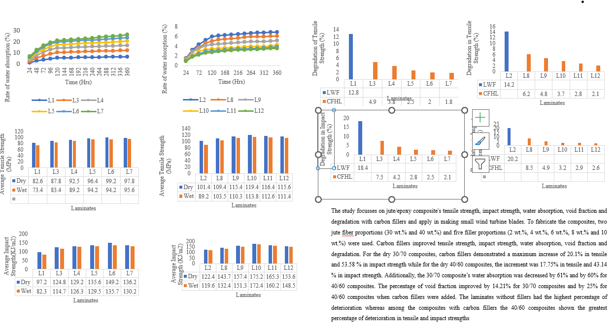
Water absorption: Table 2 depicts the water absorption of all composites. The water absorption reduced with the rise of carbon fillers content in the composite laminates due to the hydrophobic nature of the carbon fillers and their possibility to reduce the void content in the composite [26]. The 10 C 30/70 composite (L7) demonstrated the least amount of water absorption at 2.5%, reflecting a decrease of nearly 61% compared to L1. In comparison to 40/60 composites containing a similar quantity of carbon fillers, 30/70 composite with carbon fillers showed a reduced level of water absorption. The 10 C 40/60 composite (L12) has the second-lowest water absorption percentage (2.7%) with a reduction of 60% on comparison to L2. In comparison to laminate L7 of 30/70 composites, which showed the lowest percentage of water absorption, laminate L12 showed the lowest percentage of water absorption among the 40/60 carbon-filled composites with a reduction in water absorption of 8% (Figure 1 and Figure 2). In addition to decreasing moisture absorption, hybridization is expected to improve the mechanical and physical characteristics of the polymer composites [27].
Void fraction: Table 3 shows that, on comparing laminates L1 and L2 without carbon fillers, L2 void fraction is 13.65% smaller than L1. The percentage of void fraction improved by 14.21% for 30/70 composites and by 25% for 40/60 composites when carbon fillers were added. The 10 C 30/70 composite (L7) had the greatest void percentage of all the carbon-filled composites with 16.73% larger void fraction than the carbon-filled 10 C 40/60 composite (L12). As the fiber content increases, the void content decreases and overall efficiency and mechanical characteristics of composites are greatly impacted by the presence of voids [28]. Increased void count often indicates decreased fatigue resistance and increased susceptibility to corrosion and penetration from moisture exposure. All the filled composites have densities that are higher than those of unfilled composites; this includes the fact that adding fused silica, carbon, glass powder and mineral silica have raised the density of the composites as well as the void fraction [29].
Tensile Strength: The addition of carbon fillers enhanced the tensile strength of composite as shown in Figure 3 and Figure 4. The composite with 8 weight percent carbon fillers (L6) of 30/70 composites and 6 weight percent carbon fillers (L10) of 40/60 composite’s had the highest tensile strength. This is because the larger volume of epoxy enables to incorporate crabon fillers up to 8 weight percent in 30/70 composites and 6 weight percent in 40/60 composites before the tensile strength begins to decline as a result of weak bonding. The decrease in tensile strength with an increase in fillers is due to the agglomeration of fillers in the composite material and the weak bonding between the reinforcement and matrix [30]. The use of carbon fillers can increase tensile strength by a maximum of 17.75% for dry 40/60 composites and 20.1% for dry 30/70 composites. The dry 6C 40/60 composite (L10) had the highest tensile strength, which was 20.42% greater than the 30/70 composites maximum tensile strength (L6). The tensile strength of the dry samples was found to be superior to that of the corresponding wet samples. According to Tesfay et al., water absorption may cause quick debonding, delamination and loss of structural integrity, plasticizing the system and lowering its tensile strength [31].
Test for impact: Carbon fillers have improved the impact strength of 30/70 composites and 40/60 composites as seen in Figure 5 and Figure 6. The composite with 8 weight percent filler composition (L6) of 30/70 composites and the composite with 6 weight percent filler composition (L10) of 40/60 composites had the highest impact strength. According to Biswas et al. (2019), a further increase in fillers decreased the impact strength of the composites as filler agglomeration in the polyester results in poor fiber-matrix interaction and decreased resistance to debonding [32]. Laminates (L1 and L2) without carbon fillers are less impact-resistant than the matching composite. Addition of carbon fillers resulted in improvement of impact strength by 53.58% for the dry 30/70 composites and 43.14% for the dry 40/60 composites. The dry 6C 40/60 composite (L10) had the highest impact strength among the carbon filled composites with 17.42% more than the maximum value among the carbon filled 30/70 composites (L6). Wet composites show a similar trend in impact strength to their dry counterparts.
Composite's degradation: The composite’s tensile and impact strengths deteriorated as a result of water absorption (Figure 7, Figure 8, Figure 9 and Figure 10). The laminates without fillers (L1 and L2) had the highest percentage of deterioration. Among the composites with carbon fillers the 40/60 composites (L3, L8) shown the greatest percentage of deterioration in tensile and impact strengths by 26.5% and 13.3%, respectively. The more hydrophilic jute fibers in L2, increased the water absorption rate and made to deteriorate the tensile and impact strengths of composites more quickly than in laminates L1. Both the 30/70 and 40/60 composites showed a continuous decline in deterioration of tensile and impact strength until 10 weight percent carbon fillers were added. When compared to L1, L2 laminates, the 10-weight percent carbon filled 30/70 (L7) and (L12) composites show the least degradation in tensile strength (1.8%) and impact strength (2.1%), which is equivalent to a reduction of 86% and 59.24% respectively. Compared to the similar 40/60 hybrid composites, the 30/70 hybrid composites have demonstrated less deterioration.
Conclusion
Natural fiber-reinforced composites are a good substitute for the conventional material systems utilized in the wind industry. Wind turbine blades can be made using jute/epoxy composites that have been hybridized with carbon fillers at the proper mass fraction. These composites demonstrated enhanced mechanical and water absorption capabilities. The fillers moderately affected the tensile strength but significantly affected the void fraction, impact strength, water absorption and deteriorating properties. Fillers improve the 40/60 composites tensile and impact strengths, but the 30/70 composites perform better due to their reduced water absorption and degradation characteristics.
Author Contributions
Conceptualization, B.N.R.; methodology, B.N.R., and S.K.; validation, C.S.R., B.N.R., A.G.T., and S.K.; formal analysis, C.S.R., B.N.R., A.G.T., and S.K.; investigation, C.S.R., and B.N.R.; writing—original draft preparation, C.S.R.; writing—review and editing, B.N.R., S.K., and A.G.T.; visualization, C.S.R., B.N.R., and S.K.; supervision, B.N.R and S.K. All authors have read and agreed to the published version of the manuscript.
Funding
The research received no funding.
Data Availability Statement
Current study data are available from the corresponding author upon request.
Competing Interests
The authors have no competing interests.
References
- Oliver Summerfield-Ryan; Susan Park. The power of wind: The global wind energy industry's successes and failures. Ecological Economics. 2023, 210, 107841. [CrossRef]
- Xhao, X; Copenhaver, K; Wang, L; Korey, M; Gardner, D.J; Li, K; Lamm, M.E; Kishore, V; Bhagia, S; Tajvidi, M; Tekinalp, H; Oyedeji, O; Wasti, S; Webb, E; Ragauskas, A.J; Zhu, H; Peter, W.H; Ozcan, S. Recycling of natural fiber composites: Challenges and opportunities. Resour. Conserv. Recycl. 2022,177, 105962. [CrossRef]
- Sachin Ghalme; Mohammad Hayat; Mahesh Harne.A comprehensive review of natural fibers: Bio-based constituents for advancing sustainable materials technology. J.Ren.Mat. 2025,13(2),273-295. [CrossRef]
- Marion, P; Andréas, R; Marie, H.M. Study of wheat gluten plasticization with fatty ac-ids. Polym.2003, 44,115-122. [CrossRef]
- Holmes John W; Brøndsted, Povl; Sørensen Bent, F; Zehui, Jiang; Zhengjun, Sun; Chen, Xuhe. Development of a bamboo-based composite as a sustainable green material for wind turbine blades. Wind Eng. 2009, 33, 197-210. [CrossRef]
- Jeyapragash R, Srinivasan V, Sathiyamurthy SJMTP. Mechanical properties of natural fiber/particulate reinforced epoxy composites–a review of the literature. Mater Today Proc. 2020; 22: 1223-1227. [CrossRef]
- Saravia, M.C; Saravia, L.J; Cortínez, V.H. A one-dimensional discrete approach for the determination of the cross-sectional properties of composite rotor blades. Renew Ener.2015, 80,713-723. [CrossRef]
- Fedon, N; Weaver, P.M; Pirrera, A; Macquart, T. A method using beam search to design the lay-ups of composite laminates with many plies. Composites Part C, 2021, 4,100072. [CrossRef]
- Thomas, L; Ramachandra, M. Advanced materials for wind turbine blade-A Review, Mater. Today. Proc. 2018, 5 (1),2635–2640. [CrossRef]
- Gherissi, A. A study of wind turbine blade structure based on cellulose fibers composite material. Proc. Eng. Technol.2018,38, 80–85.
- Ganesh, R.K; Rajashekar, P; Narayan, N. Natural fiber reinforced polymer composite materials for wind turbine blade applications. Int. J. Sci. Develop. Res. 2016, 1(9), 28-37.
- Tarfaoui, M; Shah, O; Nachtane, M. Design and optimization of composite offshore wind turbine blades. J. Energy Resour. Technol. 2019, 141 (5), 51204. [CrossRef]
- Lahcen Amzil; Saloua Fertahi; Tarik Raffak; Taoufiq Mouhib.Towards sustainable blade design: A critical review of natural fiber-reinforced hybrid composites and structural analysis tutorials. Next Mat. 2025,8,100688.
- Paulsen, U.S; Madsen, H.A; Hattel, J.H; Baran, I; Nielsen,P.H. Design optimization of a 5 MW floating offshore vertical-axis wind turbine. Energy Proc.2013, 35, 22–32. [CrossRef]
- Su, H; Dou, B; Qu, T; Zeng, P; Lei, L. Experimental investigation of a novel vertical axis wind turbine with pitching and self-starting function. Energy Convers Manag. 2020,217,113012. [CrossRef]
- Rajak, D.K; Pagar, D.D; Menezes, P.L; Linul, E. Fiber-reinforced polymer composites: manufacturing, properties, and applications, Polymers.2019, 11 (10),1667. [CrossRef]
- Das, S.C; Sheikh, A.E.K; Sayeed, M. A; Suruzzaman Paul; Dhar, D; Grammatikos, S.A. On the use of wood charcoal filler to improve the properties of natural fiber reinforced polymer composites. Mater. Today. 2020, 44:926–929. [CrossRef]
- Dinesh, S; Kumaran, S. Mohanamurugan, R; Vijay, D. L; Singaravelu, A; Vinod, M; Sanjay, R; Siengchin, P.S; Bhat, K.S. Influence of wood dust fillers on the mechanical, thermal, water absorption and biodegradation characteristics of jute fiber epoxy composites. J. Poly. Res. 2020, 27,1–13. [CrossRef]
- Mishnaevsky, L; Branner, K; Petersen, H.N; Beauson, J; McGugan, M; Sørensen, B.F. Materials for wind turbine blades: An overview. Materials.2017,10,1285. [CrossRef]
- Sever, K; Sarikanat, M; Seki, Y; Erkan, G; Erdogan, U.H; Erden, S. Surface treatments of jute fabric: The influence of surface characteristics on jute fabrics and mechanical properties of jute/polyestercomposites.Ind.Crops.Prod.2012,35,22–30. [CrossRef]
- Saiteja, J; Jayakumar, V; Bharathiraja, G. Evaluation of mechanical properties of jute fiber/carbon nano tube filler reinforced hybrid polymer composite. Mater. Today. Proc. 2019, 22(3),756-758. [CrossRef]
- Rana, A. K; Mandal, A; Mitra, B. C; Jacobson, R; Rowell, R; Banerjee, A. N. Short jute fiber-reinforced polypropylene composites: Effect of compatibilizer. J. Appl. Polym. Sci. 1998, 69, 329−338. [CrossRef]
- Le, T. M; Pickering, K. L. The potential of harakeke fibre as reinforcement in polymer matrix composites including modelling of long harakeke fibre composite strength. Composites Part A: Appl. Sci. Manufac.2015,76, 44-53. [CrossRef]
- Shah, D. U; Porter, D; Vollrath, F. (2014). Can silk become an effective reinforcing fibre? A property comparison with flax and glass reinforced composites. Composites. Sci. Tech.101,173-183.
- Charlet, K; Baley, C; Morvan, C; Jernot, J. P; Gomina, M; Bréard, J. Characteristics of Hermès flax fibres as a function of their location in the stem and properties of the derived unidirectional composites. Composites Part A: Appl.Sci. Manufac. 2007, 38(8), 1912-1921. [CrossRef]
- Ganapathy, T; Sathiskumar, R; Sanjay, M.R; Senthamaraikannan, P; Saravanakumar, S.S; Parameswaranpillai, J; Siengchin, S. Effect of graphene powder on banyan aerial root fibers reinforced epoxy composites. J. Nat.Fibers.2021, 18 (7),1029–1036. [CrossRef]
- Mohd Hafiz Zamri; Md Akil Hazizan; Bakar Abu Azhar; Ahmad Arifin Zainal; Cheng Leong. Effect of water absorption on pultruded jute/glass fiber-reinforced unsaturated polyester hybrid composites. J.Compo.Mater. 2011, 46, 51-61. [CrossRef]
- Mishra, V; Biswas, S. Physical and mechanical properties of bi-directional jute fiber epoxy composites. Proc. Eng. 2013, 51:561–566. [CrossRef]
- Teh, P.L; Jaafar, M; Akil, H.M; Seetharamu, K.N; Wagiman, A.N.R; Beh K.S. Thermal and mechanical properties of particulate fillers filled epoxy composites for electronic packaging application. Poly. Adv.Technol.2008,19,308–315. [CrossRef]
- Reddy, P. V; Prasad, P.R; Krishnudu, D.M; Hussain, P. Influence of fillers on mechanical properties of Prosopis juliflora fiber reinforced hybrid composites. Mater. Today: Proc. 2019, 7, 618. [CrossRef]
- Tesfay, A. G; Kahsay, M.B; Senthil Kumar, P.S. Improvement of the degradation of tensile and impact strength of water-aged sisal fiber-reinforced polyester composites: A comparative study on the effects of hybridizations, hybrid layering sequences, and chemical treatments. J. Natu. Fibers. 2022,19 (15), 11597–11609. [CrossRef]
- Biswas, B; Hazra, B; Sarkar, A; Bandyopadhyay, N.R; Mitra, B.C; Sinha, A. Influence of ZrO2 incorporation on sisal fiber reinforced unsaturated polyester composites. Poly.Compos.2019, 40,2790–801. [CrossRef]
Figure 1.
Impact of carbon fillers on water absorption rate of 30/70 composites.
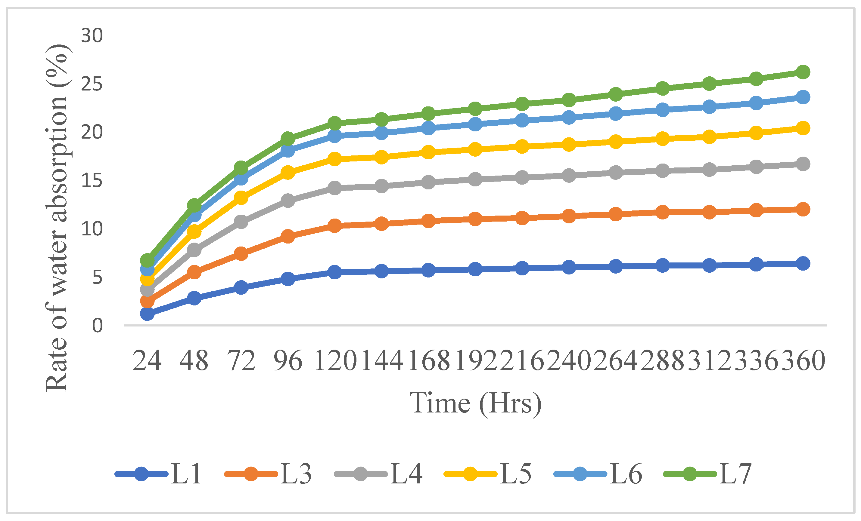
Figure 2.
Impact of carbon fillers on water absorption rate of 40/60 composites.
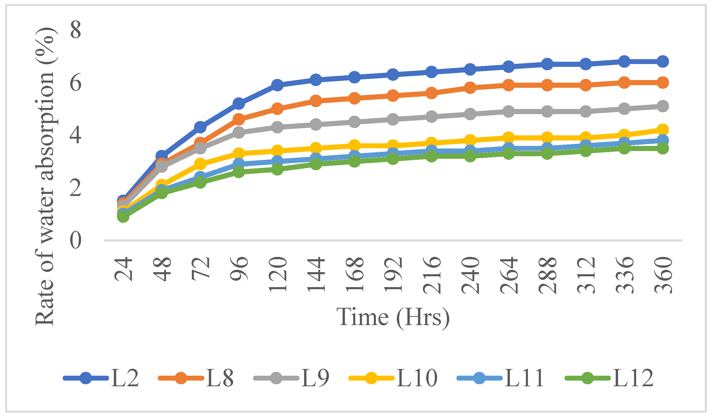
Figure 3.
Impact of carbon fillers on tensile strength of 30/70 composites.
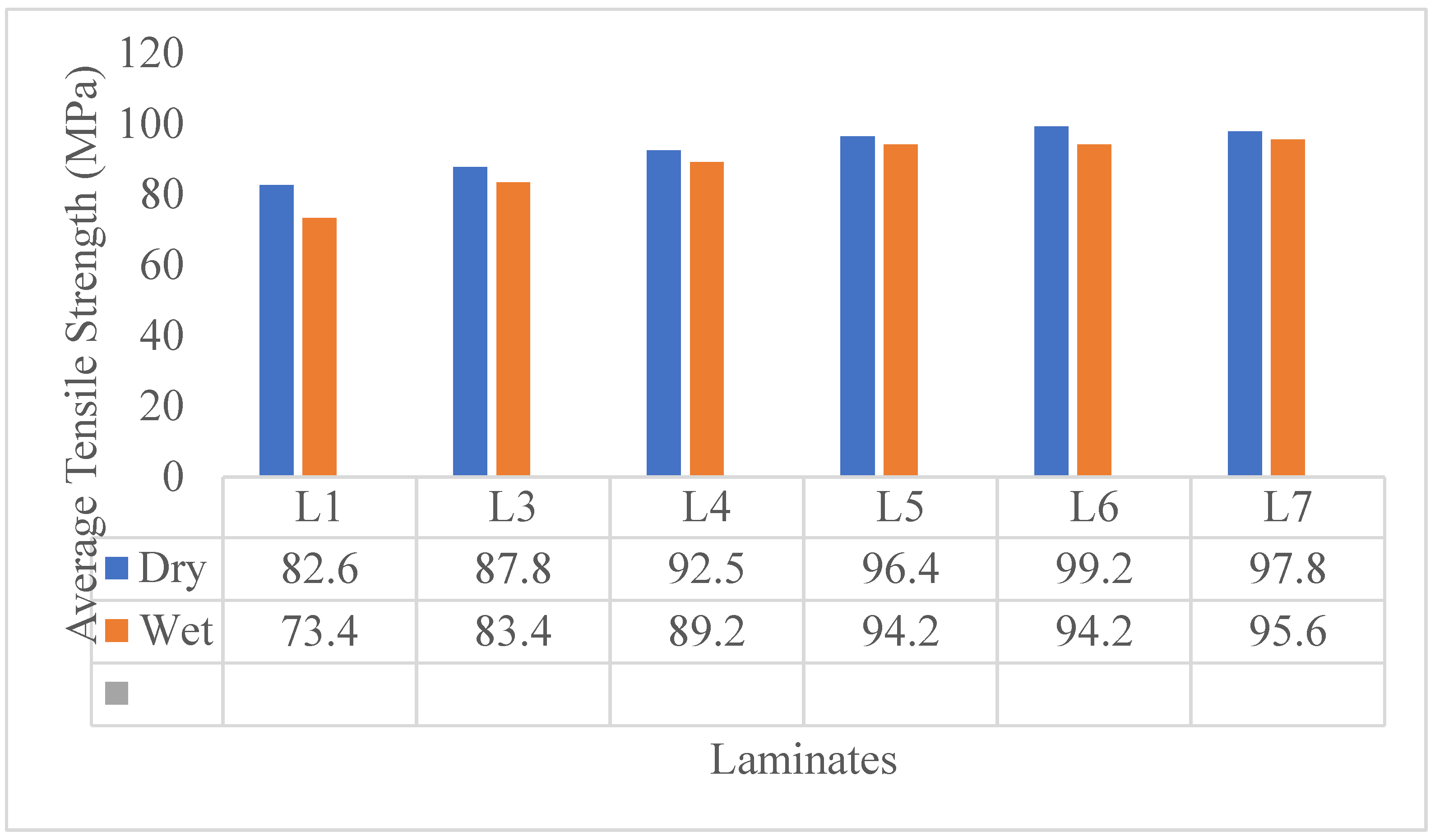
Figure 4.
Impact of carbon fillers on tensile strength of 40/60 composites.
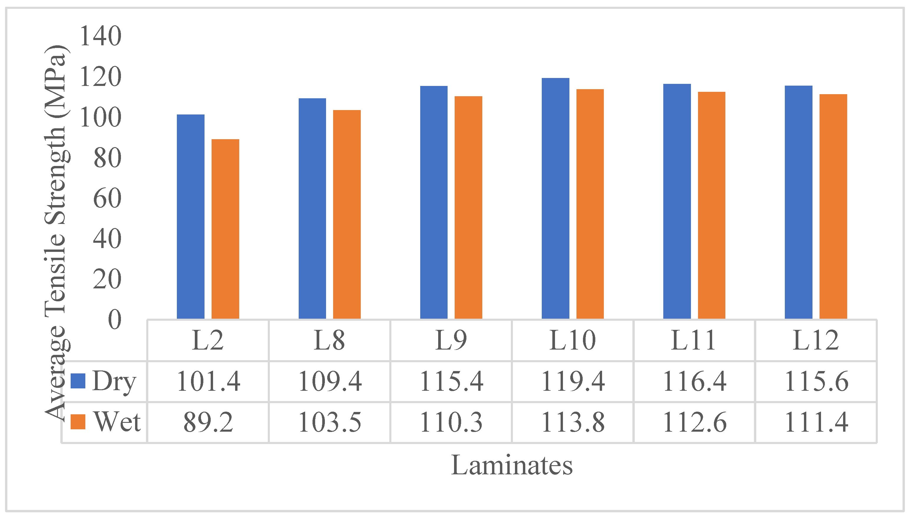
Figure 5.
Impact of carbon fillers on strength of impact of 30/70 composites.
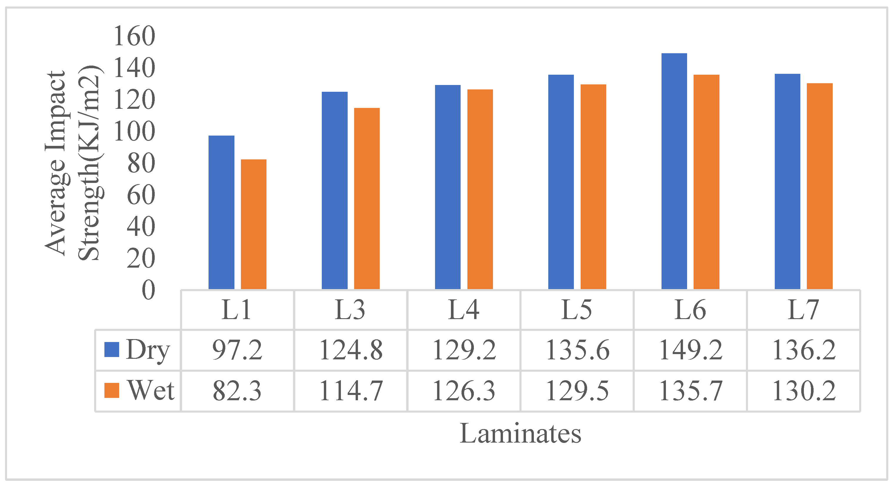
Figure 6.
Impact of carbon fillers on strength of impact of 40/60 composites.
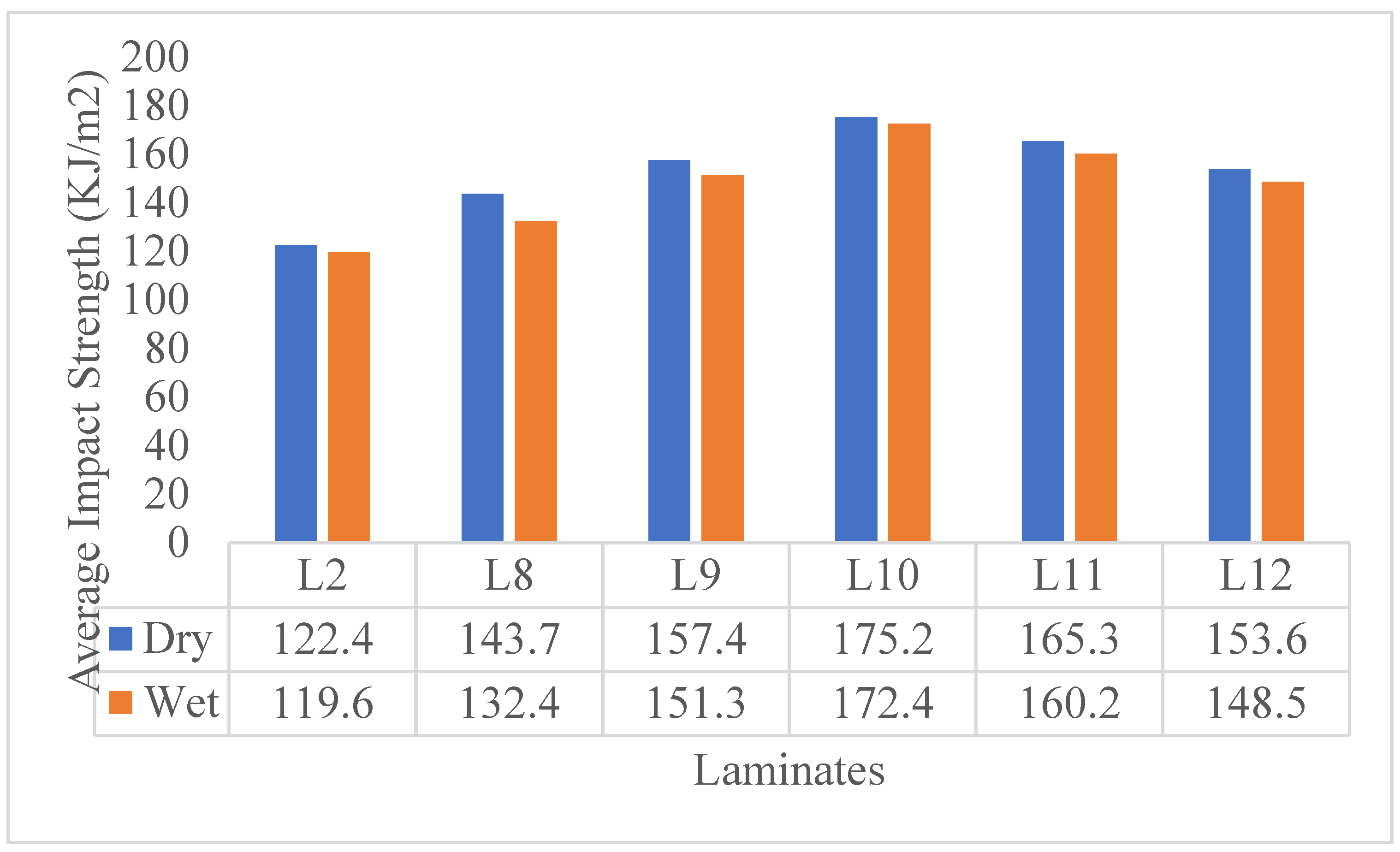
Figure 7.
Impact of carbon fillers on degradation of tensile strength of 30/70 composites.
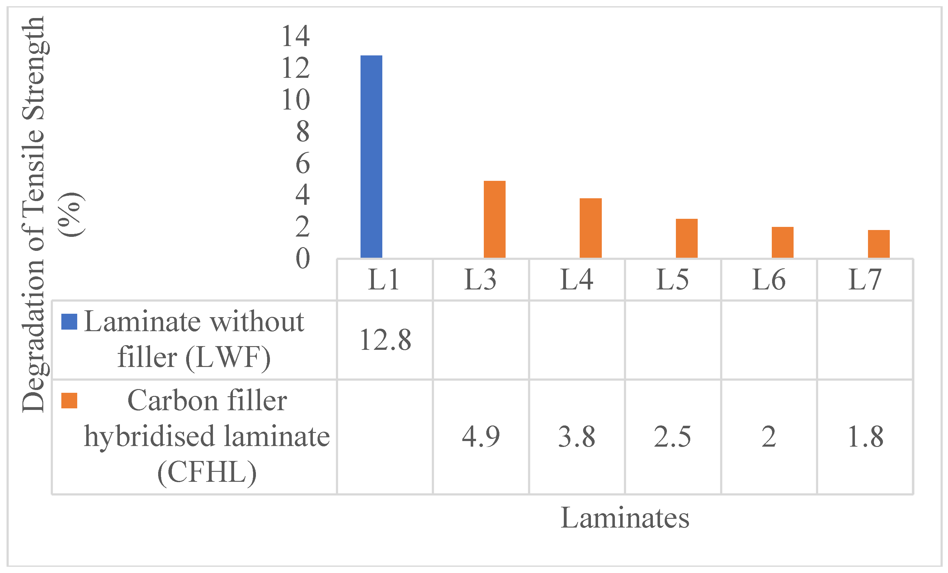
Figure 8.
Impact of carbon fillers on degradation of tensile strength of 40/60 composites.
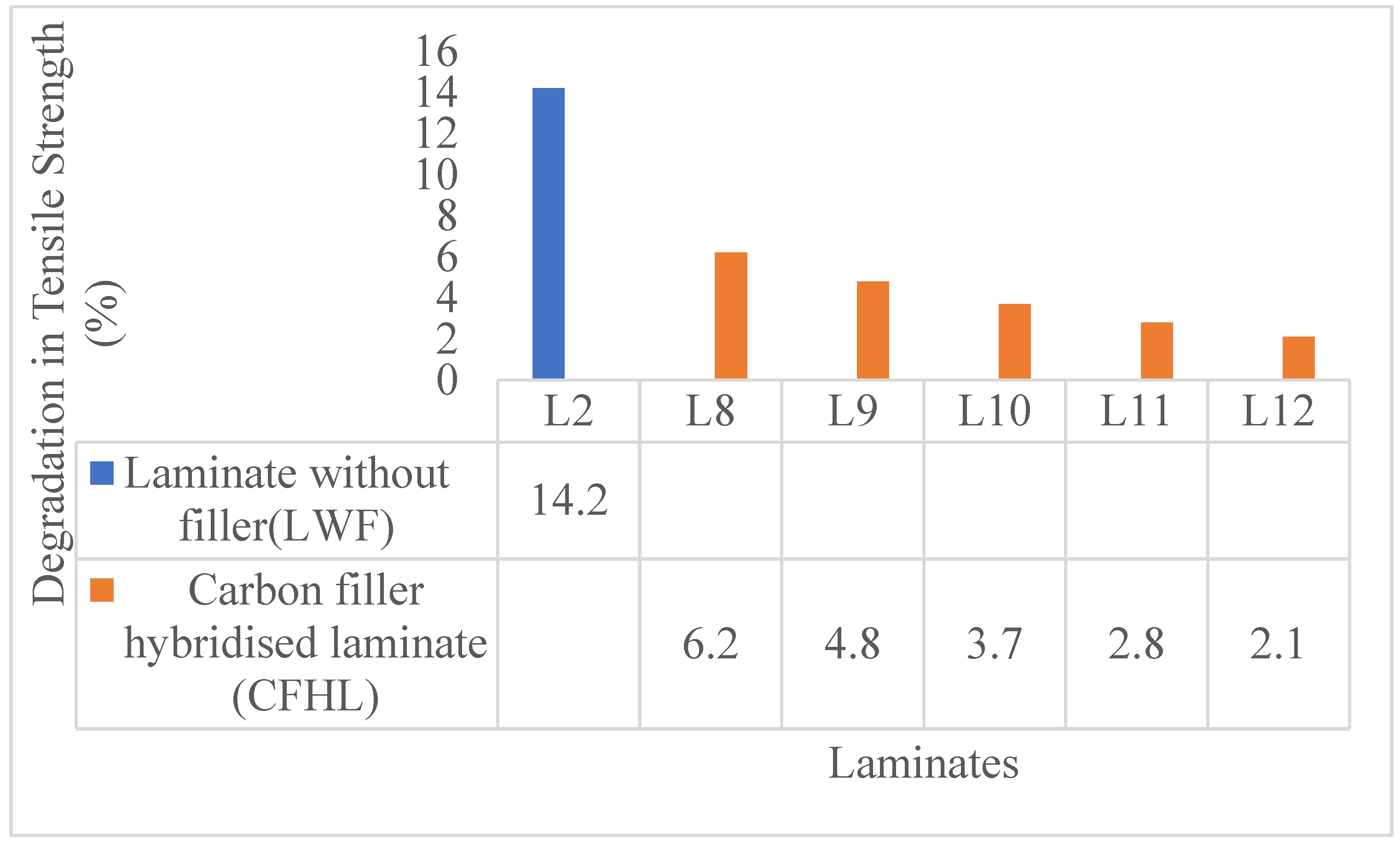
Figure 9.
Impact of carbon fillers on degradation of impact strength of 30/70 composites.
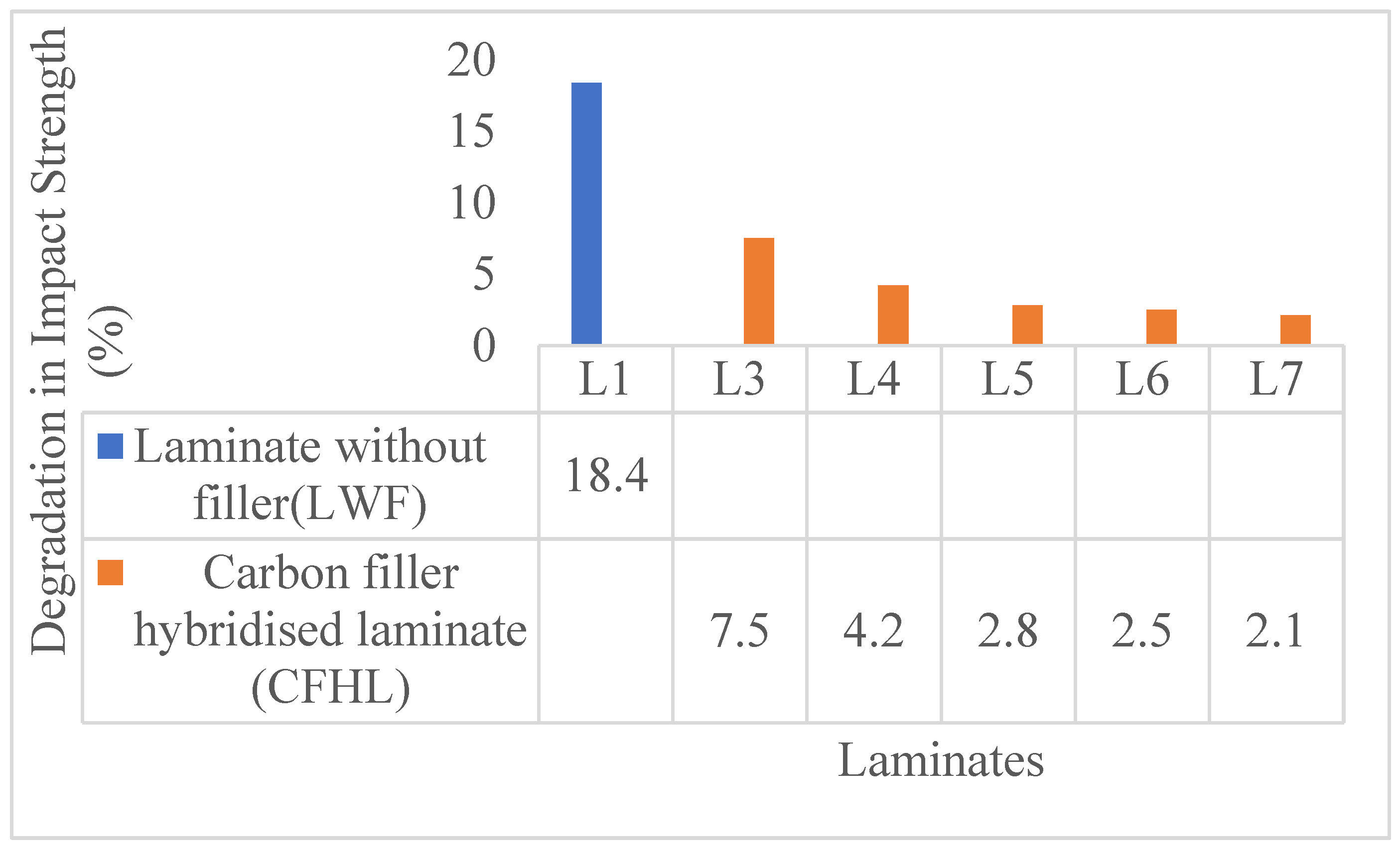
Figure 10.
Impact of carbon fillers on impact strength degradation of composites 40/60.
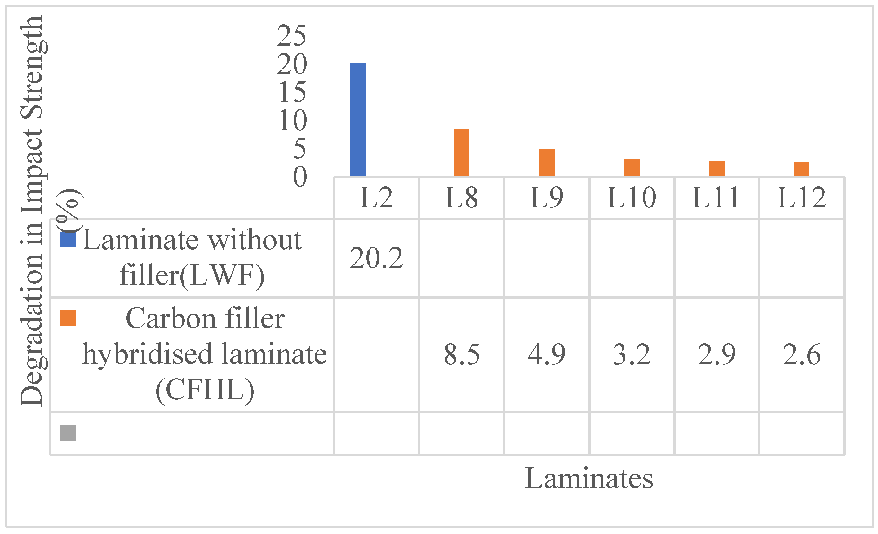

Table 1.
Content of composite and its classification.
| Laminate | Classification | Composition |
| L1 | Composite 30/70 | 30 wt% jute fiber + 70 wt% Epoxy |
| L2 | Composite 40/60 | 40 wt% jute fiber +60 wt% Epoxy |
| L3 | C2, Composite 30/70 | Carbon filler (2% of the 30/70 composite) + 30/70 composite |
| L4 | C4, Composite 30/70 | Carbon filler (4% of the 30/70 composite) + 30/70 composite |
| L5 | C6, Composite 30/70 | Carbon filler (6% of the 30/70 composite) + 30/70 composite |
| L6 | C8, Composite 30/ 70 | Carbon filler (8% of the 30/70 composite) + 30/70 composite |
| L7 | C10, Composite 30/ 70 | Carbon filler (10% of the 30/70 composite) + 30/70 composite |
| L8 | C2, Composite 40/60 | Carbon filler (2wt% of the 40/60 composite) + 40/60 composite |
| L9 | C4, Composite 40/60 | Carbon filler (4wt% of the 40/60 composite) + 40/60 composite |
| L10 | C6, Composite 40/60 | Carbon filler (6wt% of the 40/60 composite) + 40/60 composite |
| L11 | C8, Composite 40/60 | Carbon filler (8wt% of the 40/60 composite) + 40/60 composite |
| L12 | C10, Composite 40/60 | Carbon filler (10wt% of the 40/60 composite) + 40/60 composite |
Table 2.
Water absorption percentage at composite’s saturation.
| Laminate | % of water absorption (Average % ± SD) |
| L1 | 6.4 ± 0.16 |
| L2 | 6.8 ± 0.23 |
| L3 | 4.9 ± 0.12 |
| L4 | 4.0 ± 0.16 |
| L5 | 3.3 ± 0.18 |
| L6 | 2.8 ± 0.14 |
| L7 | 2.5± 0.12 |
| L8 | 5.0 ± 0.16 |
| L9 | 4.1 ± 0.12 |
| L10 | 3.8 ± 0.14 |
| L11 | 3.1 ± 0.13 |
| L12 | 2.7± 0.14 |
Table 3.
Different composites void fraction.
| Laminate | Composition |
Theoretical Density
(ρt g/cm3) |
Experimental Density
(ρ exp g/cm3) |
Void Fraction (%) |
| L1 | 30 wt% jute fiber + 70 wt% Epoxy | 1.164 ± 0.016 | 1.107±0.021 | 4.91±0.005 |
| L2 | 40 wt% jute fiber +60 wt% Epoxy | 1.153 ± 0.014 | 1.104±0.016 | 4.24±0.002 |
| L3 | 2% carbon filler of the composite 30/70 + composite 30/70 | 1.172 ± 0.025 | 1.110±0.032 | 5.29±0.007 |
| L4 | 4% carbon filler of the composite 30/70 + composite 30/70 | 1.175 ± 0.021 | 1.111±0.025 | 5.44±0.004 |
| L5 | 6% carbon filler of the composite 30/70 + composite 30/70 | 1.181±0.018 | 1.115±0.026 | 5.59±0.008 |
| L6 | 8% carbon filler of the 30/70 composite + composite 30/70 | 1.185±0.023 | 1.118±0.027 | 5.65±0.004 |
| L7 | 10% carbon filler of the 30/70 composite + composite 30/70 | 1.187± 0.024 | 1.120±0.029 | 5.73±0.005 |
| L8 | 2% carbon filler of the composite 40/60 + composite 40/60 | 1.168 ± 0.025 | 1.108±0.032 | 5.14±0.007 |
| L9 | 4% carbon filler of the composite 40/60 + composite 40/60 | 1.173 ± 0.021 | 1.110±0.025 | 5.37±0.005 |
| L10 | 6% carbon filler of the composite 40/60 + composite 40/60 | 1.177 ± 0.024 | 1.112±0.028 | 5.52±0.004 |
| L11 | 8% carbon filler of the composite 40/60 + composite 40/60 | 1.182 ± 0.025 | 1.116±0.035 | 5.58±0.002 |
| L12 | 10% carbon filler of the composite 40/60 + composite 40/60 | 1.185 ± 0.026 | 1.118±0.036 | 5.65±0.008 |
Disclaimer/Publisher’s Note: The statements, opinions and data contained in all publications are solely those of the individual author(s) and contributor(s) and not of MDPI and/or the editor(s). MDPI and/or the editor(s) disclaim responsibility for any injury to people or property resulting from any ideas, methods, instructions or products referred to in the content. |
© 2025 by the authors. Licensee MDPI, Basel, Switzerland. This article is an open access article distributed under the terms and conditions of the Creative Commons Attribution (CC BY) license (http://creativecommons.org/licenses/by/4.0/).
Copyright: This open access article is published under a Creative Commons CC BY 4.0 license, which permit the free download, distribution, and reuse, provided that the author and preprint are cited in any reuse.


