
Submitted:
30 October 2024
Posted:
31 October 2024
You are already at the latest version
Abstract
The poor impact resistance of carbon fiber reinforced composites limits their application in broader fields. In this study, a toughened epoxy resin (E2) modified with toughening agents and a micron-sized toughening particle (TP) were developed. Standard epoxy resin (E1), toughened epoxy resin (E2), and TP-toughened E2 resin (E3) were prepared into prepregs with SYT55-12K carbon fiber and ultimately fabricated into carbon fiber reinforced composites. The mechanical properties of the resins and the composites, particularly the compression properties, were characterized. The failure morphology of the composites and the distribution of toughening particles were observed using scanning electron microscopy (SEM), ultrasonic C-scan testing, and metallographic microscopy. It was found that the toughening agents improved the bending strength of the resin by approximately 12%, while the incorporation of TP enhanced the impact performance of the resin by 122%. Further characterization of the mechanical properties of the carbon fiber reinforced composites revealed that, with the addition of toughening agents, the resin increased the 0° bending strength of the composites by 29.9% and the 0° compressive strength by 34.3%. Additionally, significant enhancements were observed in interlaminar shear strength and open-hole compressive strength. After the addition of TP, the compressive strength of EC3 compared to EC2 increased by 74.3% after impact, while the mode I interlaminar fracture toughness increased by 34.8% and the mode II interlaminar fracture toughness improved by 67.9%. C-scan analysis indicated that the damage area of EC3 decreased by 60.7% compared to EC2, demonstrating that the particle toughening significantly enhanced the impact resistance of the composites. The compression failure of the TP-toughened EC3 exhibited typical characteristics of kink band failure, and the micron-sized particles were able to significantly balance and absorb loads. The findings of this study indicate that resin toughening can significantly improve the 0° compressive strength of carbon fiber reinforced composites, and that the use of micron-sized toughening particles can markedly enhance the post-impact compressive strength of the composites through interlaminar toughening. This research provides insights for improving the compressive and impact resistance performance of carbon fiber reinforced composites, with implications for industrial application and guidance for further industrialization trials.
Keywords:
matrix resin
; particle toughening
; carbon fiber composites
; compressive properties
1. Introduction
Carbon fiber composites are being increasingly applied in modern industrial systems, such as aerospace, hydrogen storage bottles, wind turbine blades, and new energy vehicles, due to their excellent mechanical properties and lightweight characteristics [1]. These materials improve application efficiency while reducing energy consumption and carbon emissions [2]. Carbon fiber composites are prepared by combining carbon fibers with matrix resins through specific processing techniques, with the matrix resin being one of the most important components of carbon fiber composites [3]. Under the condition that the interface performance satisfies the basic connection requirements between fibers and matrix resins, the matrix resin determines the fundamental mechanical properties of the fiber composites under the same fiber conditions. In China, efforts have been concentrated over the past few decades on solving the bottleneck technical challenges associated with carbon fibers [4]. Research on carbon fiber composites has primarily focused on fiber and interface studies, with insufficient understanding of how matrix resins influence the overall performance of composites. The compressive strength of carbon fiber composites is significantly lower than their tensile strength, and their poor impact resistance largely restricts their application expansion. Enhancing the compressive strength and impact resistance of carbon fiber composites has become a challenge faced by the industry and a hot research topic [5,6,7,8]. Currently, the addition of nanomaterials to matrix resins is considered an effective approach to improving the compressive strength and impact resistance of carbon fiber composites [9]. Researchers have made positive progress in enhancing the compressive strength, impact resistance, and fracture toughness of carbon fiber composites by incorporating various nanomaterials, including rubber particles or carbon black [10,11,12,13], carbon nanotubes [14,15,16,17,18], graphene or graphene oxide [19,20,21,22,23], nano-clays [24,25,26,27], nano-silica [25,26,27,28,29,30,31,32,33], thermoplastic particles [34,35], and other nanostructures [36,37,38,39]. However, the main limitation of these studies is that they are often conducted at the laboratory level, focusing on one or several properties of composites. These investigations are not sufficiently systematic and present challenges in material selection and process design, thereby failing to provide direct references for industrial applications.
This study prepares a toughening resin and a toughening particle, aiming to comprehensively analyze the effects of resin and particle toughening on the compressive performance of carbon fiber composites under industrial conditions. The core finding is that enhancing the compressive performance of carbon fiber composites is primarily linked to the matrix resin. Toughening the matrix resin can significantly improve the compressive performance of carbon fiber composites. Additionally, further toughening the resin with micron-sized particles can substantially enhance post-impact compressive performance and interlaminar fracture toughness. This approach is markedly different from the commonly conducted research on nanomaterial toughening systems and has direct implications for industrial applications.
2. Experimental Section
2.1. Experimental Materials
The carbon fiber used in this experiment was commercial dry-jet wet-spun SYT55-12K carbon fiber produced by Zhongfu Shenying Carbon Fiber Co., Ltd. The carbon fiber was prepared into prepreg on an industrial prepreg production line. A self-made toughening particle was designated as TP. The matrix resins used were the commercially available WP-5100 epoxy resin system from Wells Advanced Materials (Shanghai) Co., Ltd., a self-made high-toughness epoxy resin system, and a self-made high-toughness epoxy resin system with TP toughening, which were designated as E1, E2, and E3, respectively. The prepregs were prepared into composite materials, and the resulting samples were designated as EC1, EC2, and EC3.
2.2. Experimental Equipment
The equipment for the prepreg production line was provided by Flourish International Co., Ltd., model FHPM-02-1270. The prepreg cutting machine was supplied by Hangzhou Aike Technology Co., Ltd., model BK3C2513. The autoclave was manufactured by Shandong Zhonghang Taida Composite Materials Co., Ltd., model R2021-0011. The tensile testing machine was produced by Shimadzu Corporation, model AG-XPLUS. The precision engraving milling machine was supplied by QiaoKe CNC Machinery Equipment Co., Ltd., model QK6090-1. The hot air circulation drying oven was provided by Suzhou Deruipu Oven Manufacturing Co., Ltd., model DRP-8803. The vernier caliper was manufactured by SATA Tools (Shanghai) Co., Ltd., model SATA 91511. The toughening resin and toughening particles were prepared using self-developed pilot-scale equipment.
2.3. Experimental Content
Preparation of Toughening Particles:
The specific details regarding the preparation of toughening particles involve trade secrets and will not be disclosed. The detailed process is illustrated in the following figure:
Figure 1.
Process Flow Diagram for Toughening Particles (TP).
Preparation of Toughened Resin Systems and Particle-Toughened Resin Systems:
The specific preparation details of the toughened resin systems E2 and the particle-toughened resin systems E3 involving the aforementioned TP particles are considered proprietary and will not be disclosed. The preparation process is outlined as follows:
Figure 2.
Process Flow Diagram for Toughened Resin System (E2) and TP-Toughened E2 (E3) Resin Systems.
Figure 2.
Process Flow Diagram for Toughened Resin System (E2) and TP-Toughened E2 (E3) Resin Systems.
Preparation of Prepregs and Composite Materials:
The prepreg production line operates with 548 fibers, with a fiber areal density controlled at 194 g/m² and a width maintained at 1270 mm. The resin content is controlled at 34%, and the running line speed is set to 2 m/min.
Carbon fiber composite laminates are produced from the cut prepregs using an autoclave. The autoclave process is conducted as follows: the temperature is maintained at 70 °C for 70 minutes, followed by a heating rate of 1.5 °C/min to 130 °C, which is then held at 0.6 MPa for 130 minutes. The laminates are subsequently cut into the required dimensions for testing using a precision milling machine.
2.4. Characterization Methods
Characterization of the Resin:
(1) The mechanical properties of the resin are tested according to the GB/T 2567-2021 standard for performance testing of resin castings, including tensile strength, flexural strength, and impact strength. The melting conditions are set to 140 °C for 2 hours, and the curing conditions are set to 170 °C for 2 hours, with the preparation process assisted by a degassing machine.
(2) The glass transition temperature (Tg) is tested using Dynamic Mechanical Analysis (DMA). The TA Instruments DMA 850 is utilized, with conditions set between 40 °C and 280 °C, at a heating rate of 5 °C/min, and operated in the DMA multi-frequency strain mode at a frequency of 1.0 Hz, following the ASTM E1545-2011 standard test method for the glass transition temperature of polymers via thermomechanical analysis. The storage modulus (E') reflects the elastic characteristics of the sample and indicates its ability to fully recover from deformation. The loss modulus (E") represents the viscous characteristics of the sample, indicating the heat loss during deformation. The loss factor (tanδ), defined as the ratio of the loss modulus to the storage modulus, reflects the vibration absorption capability.
Characterization of Carbon Fibers:
The testing process is controlled at an ambient temperature of 25 °C ± 1 °C and relative humidity below 45%. The linear density, tensile strength, Young's modulus, and elongation at break of the carbon fibers are measured according to the GB/T 3362-2017 standard. The resin content of the fibers is determined using the Soxhlet extraction method specified in GB/T 29761-2022 Method A.
Characterization of Carbon Fiber Composites:
(1) The tensile strength and tensile modulus at 0° were determined according to ASTM D3039/D3039M-2014, which specifies standard testing methods for the tensile properties of polymer matrix composites.
(2) The flexural strength and flexural modulus at 0° were measured in accordance with ASTM D7264/D7264M-2015, which outlines the standard test methods for the flexural properties of polymer matrix composites.
(3) The compressive strength and compressive modulus at 0° were evaluated according to SACMA SRM 1R-94, which specifies the testing method for the compressive properties of oriented fiber-resin composites.
(4) The compressive strength after impact (CAI) was assessed in accordance with ASTM 7136/D7136M-20, which measures the damage resistance of fiber-reinforced polymer matrix composites to drop impact events, combined with ASTM D7137/D7137M-17, which details the standard testing method for the residual compressive strength characteristics of damaged polymer matrix composite plates. An impact head with a diameter of 16 mm was utilized, with the impact energy calibrated to 6.7 J/mm. The dimensions of the specimen were 150 mm × 100 mm × 4.5 mm, leading to an impact energy calculation of 4.5 mm × 6.7 J/mm = 30.15 J.
(5) The open-hole tensile strength (OHT) was determined according to ASTM D5766/D5766M-2011, which provides the standard test method for the open-hole tensile strength of polymer matrix composite laminates. The dimensions of the open-hole tensile specimen were 300 mm × 36 mm × 3 mm with a hole diameter of 6 mm.
(6) The open-hole compressive strength (OHC) was measured according to D6484/D6484M-2014, which outlines the standard test method for the open-hole compressive strength of polymer matrix composite laminates.
(7) The interlaminar shear strength (ILSS) was determined according to ASTM D2344/D2344M-2016, which provides the standard test method for the short-beam shear strength of polymer matrix composites and their laminates.
(8) The mode I interlaminar fracture toughness (GIC) was assessed in accordance with ASTM D 5528/D 5528M-2013, which specifies the standard test method for the mode I interlaminar fracture toughness of unidirectional fiber-reinforced polymer matrix composites.
(9) The mode II interlaminar fracture toughness (GIIC) was evaluated using the CTS5026 testing method, which measures the mode II interlaminar fracture toughness of unidirectional carbon fiber reinforced polymer matrix composites under mode II shear loading using edge-notched beam specimens.
(10) A C-scan was performed on the composite plates subjected to an impact energy of 30.15 J using the NBYSH-C011 ultrasonic flaw detector, following the method outlined in ASTM D7136/D7136M-20.
(11) The morphology of the compression fracture surfaces of the carbon fiber composites was observed under a Hitachi REGULUS series SU8100 field emission scanning electron microscope.
(12) The distribution of toughening particles within the prepreg was examined using a Leica DM2700M upright metallurgical microscope.
3. Results and Discussion
3.1. Characterization of Resin Properties
3.1.1. Mechanical Properties of the Resins
The mechanical properties of three resin systems are summarized in Table 1. The tensile strength of the three resin systems is approximately 80 MPa. The addition of toughening particles resulted in an approximately 9% increase in the tensile strength of E3, indicating that the toughening particles allow E3 to bear tensile loads more evenly and distribute them better, with the interpenetrating structure contributing to enhanced strength. The bending strengths of the toughened E2 and E3 resins increased by approximately 14% and 7%, respectively, compared to E1. Toughening resulted in a decrease in the modulus of the resin systems; the addition of toughening particles led to further reductions in the tensile and bending moduli of E1, E2, and E3, which exhibited a downward trend. The incorporation of toughening agents and particles led to a certain reduction in the stiffness of the resin systems, resulting in lowered modulus performance while the elongation at break increased. E3 showed an increase of 1.29 percentage points in elongation at break compared to E2. Toughening enhanced the impact strength of the resins, with the toughening particles significantly contributing to this improvement. The impact strength of E2 increased by 12% compared to E1, while E3 improved by 110% and 87% compared to E1 and E2, respectively.

Table 1.
Mechanical Properties of Three Resin Systems.
| E1 | E1-CV/% | E2 | E2-CV/% | E3 | E3-CV/% | |
| Tensile strength/MPa | 80.76 | 4.10 | 78.25 | 7.16 | 85.27 | 6.30 |
| Young’s modulus/GPa | 3.3 | 4.63 | 3.24 | 6.23 | 2.86 | 8.20 |
| Elongation at break/% | 3.15 | 12.28 | 3.29 | 11.74 | 4.58 | 14.38 |
| Bending strength/MPa | 136.38 | 5.29 | 156.12 | 4.06 | 145.42 | 1.00 |
| Bending modulus/GPa | 3.31 | 3.08 | 3.28 | 2.77 | 2.90 | 1.40 |
| Impact strength/kJ/m2 | 19.84 | 12.41 | 22.23 | 8.90 | 41.68 | 9.48 |
Figure 3.
Comparison of Mechanical Properties of Three Resin Systems.
3.1.2. Thermodynamic Properties of the Resins
From Figure 4, it can be seen that the storage modulus (E1) starts to decline at a relatively low temperature and at a rapid rate. The loss modulus curve exhibits a distinct single peak, as E1 is a medium-temperature resin system. The inherent properties of the resin determine its glass transition temperature (Tg) to be around 130°C; therefore, the storage modulus begins to decrease rapidly at approximately 110°C. Conversely, E2 and E3 are high-temperature systems; the storage modulus of the toughened E2 begins to drop rapidly around 180 °C and stabilizes thereafter. The storage modulus curve of E3 exhibits dual platforms due to the incorporation of toughening particles, with the low-temperature platform commencing a decline around 145 °C, indicative of the toughening particles, and the high-temperature platform beginning to drop around 180 °C, reflective of the resin. Both the loss modulus and loss factor curves display dual peaks, indicating poor compatibility between the toughening particles and resin, thus suggesting the existence of a biphasic structure. The DMA spectra indicate three methods for determining the glass transition temperature (Tg): the onset temperature of the storage modulus curve, and the peak temperatures of the loss modulus and loss factor curves, with these temperatures progressively increasing. According to ISO standards, it is recommended to use the peak temperature of the loss modulus as the Tg. The Tg values determined from the loss modulus (E") peak temperatures for E1, E2, and E3 were 131.1 °C, 204.7 °C, and 149.9 °C / 204.8 °C, respectively.
Figure 4.
DMA Plots of Three Resin Systems (a Storage Modulus, b Loss Modulus, c Loss Factor).
Table 2.
Tg Results of Three Resin Systems (DMA).
| The onset temperature of the E´ curve | The peak temperature of the E" curve | The peak temperature of the Tanδ curve | |
| E1 | 128.0 | 131.1 | 148.4 |
| E2 | 197.9 | 204.7 | 224.4 |
| E3 | 141.4 | 149.9 | 154.9 |
| 200.8 | 204.8 | 224.4 |
3.2. Effect of Toughened Matrix Resin on the Compressive Properties of Carbon Fiber Composites
3.2.1. Mechanical Properties of Carbon Fiber
The carbon fiber used in this batch of experiments was produced from the same batch on the production line. The mechanical property data of the carbon fiber is provided below:
Table 3.
Mechanical Properties Data of SYT55-12K Carbon Fiber.
| Linear density mg/m | Density g/cm3 |
Sizing agent content /% | Tensile strength/MPa | Young's modulus/GPa | |
| Test value | 453 | 1.7796 | 1.12 | 6089 | 297 |
| CV/% | 1.1 | 2.4 | 1.7 | 3.9 | 0.7 |
3.2.2. Mechanical Properties Analysis of Carbon Fiber Composites
The mechanical properties of each composite sample were tested following the aforementioned methods, with the data results presented in the table below.
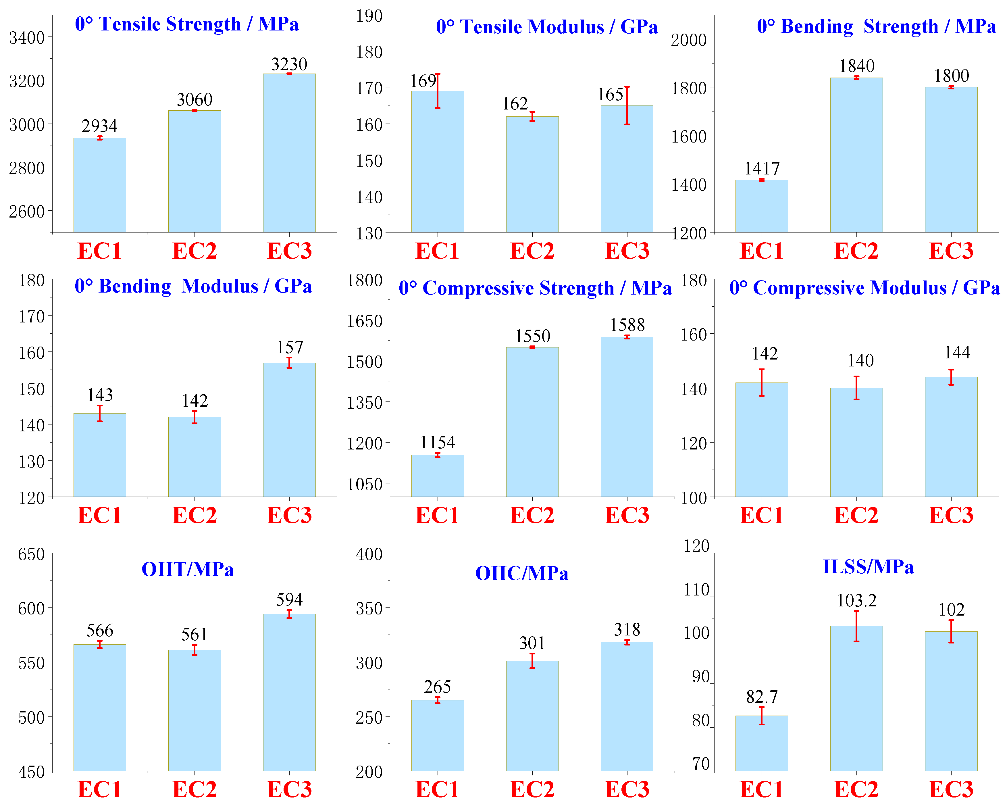
Table 4.
Mechanical Properties Data of Carbon Fiber Composites under Three Resin Systems.
| EC1 | EC2 | EC3 | EC1-CV/% | EC2-CV/% | EC3-CV/% | |
| 0° Tensile Strength / MPa | 2934 | 3060 | 3230 | 7.6 | 2.1 | 1.5 |
| 0° Tensile Modulus / GPa | 169 | 162 | 165 | 4.7 | 1.3 | 5.2 |
| 0° Flexural Strength / MPa | 1417 | 1840 | 1800 | 4.2 | 5.6 | 4.7 |
| 0° Flexural Modulus / GPa | 143 | 142 | 157 | 2.2 | 1.7 | 1.4 |
| ILSS-RTD/MPa | 82.7 | 103.2 | 102.0 | 2.0 | 3.5 | 2.6 |
| 0° Compressive Strength / MPa | 1154 | 1550 | 1588 | 7.8 | 3.3 | 6.0 |
| 0° Compressive Modulus / GPa | 142 | 140 | 144 | 4.9 | 4.2 | 2.8 |
| OHT / MPa | 566 | 561 | 594 | 3.4 | 4.7 | 3.7 |
| OHC / MPa | 265 | 301 | 318 | 2.7 | 6.7 | 2.1 |
| CAI / MPa | 163 | 167 | 291 | 6.8 | 5.0 | 4.4 |
| GⅠC /J/m2 | 348 | 400 | 539 | 2.5 | 2.9 | 6.9 |
| GⅡC/J/m2 | 968 | 1200 | 2015 | 10.1 | 8.3 | 9.5 |
By comparing EC2 and EC1, it was found that the toughening of the matrix resin had a minor effect on the tensile strength and modulus of the carbon fiber composites, as the 0° tensile strength, open hole tensile strength, 0° tensile modulus, 0° bending modulus, and 0° compressive modulus showed slight decreases, maintaining an overall similar level. This indicates that the toughening agents used to enhance the matrix resin do not significantly contribute to the tensile strength and modulus metrics of the carbon fiber composite system, as the carbon fiber or the carbon fiber composite system's properties predominantly govern these indicators. However, EC2 exhibited substantial improvements compared to EC1 in 0° bending strength, 0° compressive strength, open hole compressive strength, and interlaminar shear strength, with increases of 29.9%, 34.3%, 13.6%, and 24.8%, respectively. The trend of the 0° bending strength enhancement in EC2 is consistent with that of E2 compared to E1. The increased toughness of the resin matrix positively contributed to the bending and compressive strength improvements of the carbon fiber composites. The toughened E2 system incorporates high-functionality epoxy, enhancing the interaction between the resin matrix and the active functional groups on the carbon fiber surface, which significantly improves the interlaminar shear strength. Additionally, the toughening agent reduces the brittleness of the resin, improves impact resistance, and enhances the ability to inhibit crack initiation and propagation, significantly improving the compressive strength of the carbon fiber composites. Furthermore, a comparison of the interlaminar fracture toughness (Mode I and Mode II) showed that EC2 improved by 14.9% and 24.0%, respectively, indicating a significant enhancement in interlaminar fracture toughness due to the toughening of the matrix resin. The CAI values for EC1 and EC2 differed by only 4 MPa, indicating that the toughening of the matrix resin was insufficient to enhance the impact performance of the carbon fiber composites under the conditions of 6.7 J/mm.
Figure 5.
Mechanical Properties Test Results of Composite Materials.
EC3 was developed based on the toughened resin of EC2, with the addition of toughening particles. Comparisons indicate that EC3 exhibited slight improvements over EC2 in the 0° tensile strength, 0° flexural modulus, open-hole tensile strength, and open-hole compressive strength, with increases of 5.6%, 10.6%, 5.9%, and 5.6%, respectively. This suggests that the toughening particles played a significant role in inhibiting crack initiation and rapid propagation within the composite material system, particularly reflected in the tensile strength of carbon fiber composites, which is predominantly governed by the intrinsic properties of the carbon fiber itself. The parameters of 0° tensile modulus, 0° flexural strength, 0° compressive strength, 0° compressive modulus, and interlaminar shear strength remained at a consistent level, indicating that further toughening with particles did not contribute positively to these performance metrics.
Further comparisons of the interlaminar fracture toughness in Mode I and Mode II, as well as the Compression After Impact (CAI) index, revealed that EC3 demonstrated increases of 34.8%, 67.9%, and 74.3% respectively compared to EC2. The toughening particles exhibited exceptional performance in enhancing the impact resistance of carbon fiber composites. Under external forces, these particles effectively inhibited the generation and propagation of cracks, allowing the composite material to withstand greater external forces. This was particularly notable in the areas of post-impact compressive strength and interlaminar fracture toughness. When subjected to impact forces, cracks expanding through the interlaminar regions were obstructed by the fine particles, enabling elastic deformation to absorb impact energy, thereby reducing the driving force for further crack propagation and significantly improving the CAI.
Figure 6.
Results of GⅠC, GⅡC, and CAI for Carbon Fiber Composites.
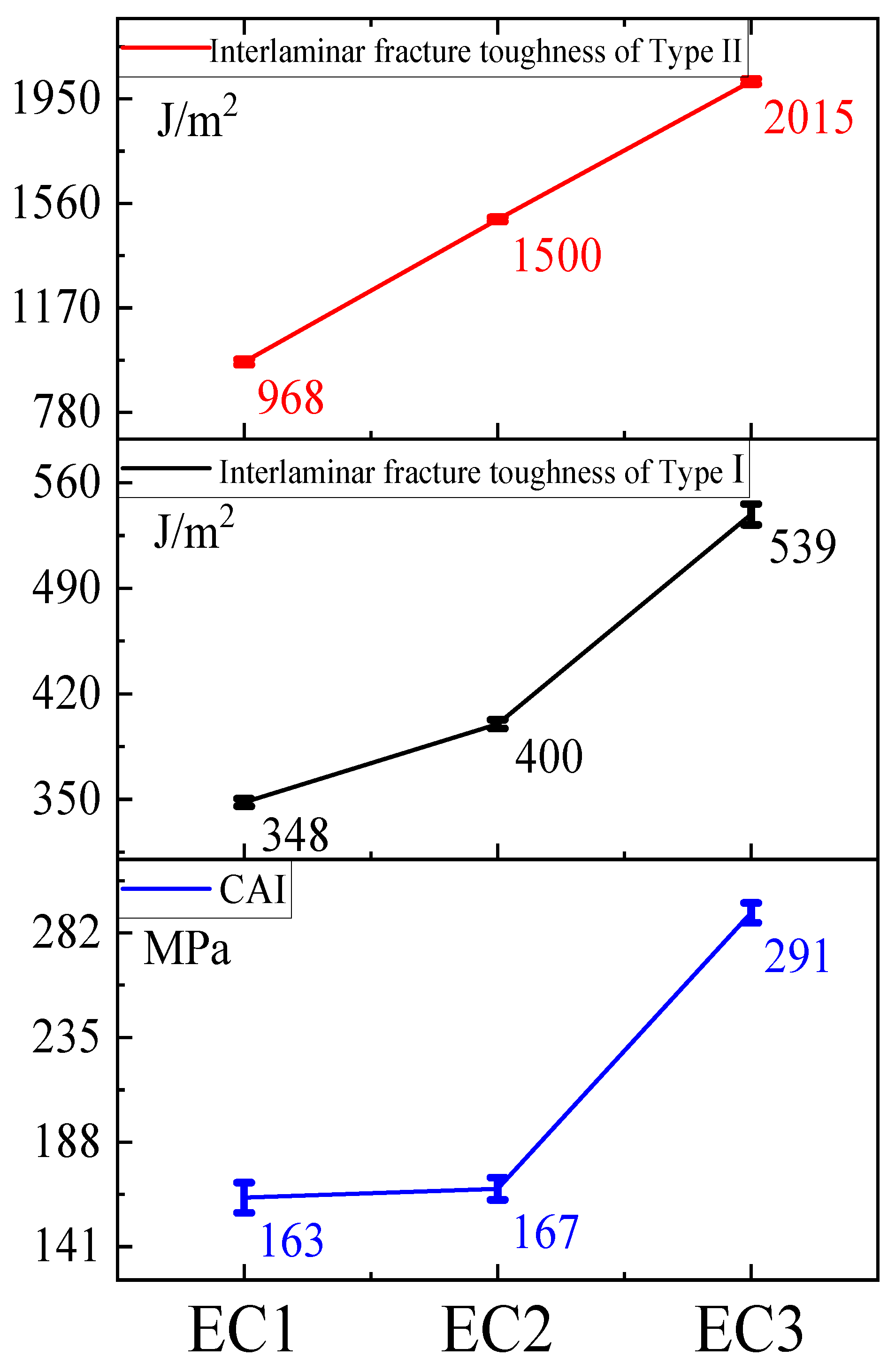
A comprehensive comparison among EC1, EC2, and EC3 indicated that the use of toughening agents in the matrix resin improved the 0° compressive strength of carbon fiber composites by 34.3%, although there was limited enhancement in post-impact compressive strength. On this basis, the further addition of toughening particles led to a 74.3% increase in post-impact compressive strength, while the further enhancement of 0° compressive strength was minimal. The toughening agents significantly improved the interlaminar fracture toughness in both GIC and GIIC modes, and further particle toughening resulted in substantial increases in both GIC and GIIC. It was concluded that the toughening of the matrix resin contributed significantly to the enhancement of compressive strength in carbon fiber composites, whereas the particle toughening made a notable contribution to improving the post-impact compressive performance of the composites.
3.2.3. Microstructural State of Particle Toughened Carbon Fiber Composites
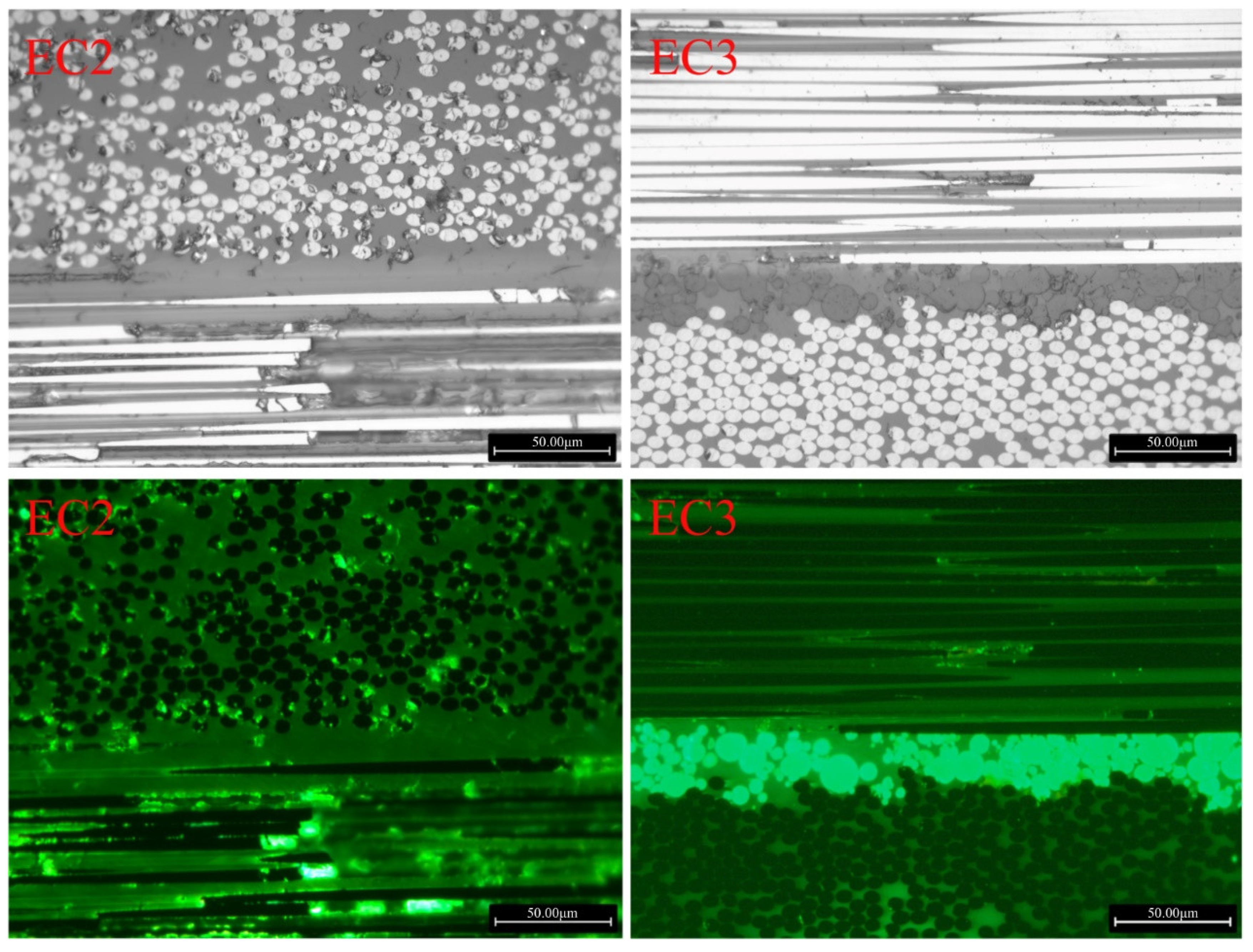
The E3 resin was dried, and the distribution state of the toughening particles in the EC3 samples was observed using a high-resolution electron microscope, as shown in Figure 7 (a) and (b). The size of the toughening particles was approximately 30 μm, significantly larger than the carbon fiber diameter (about 5 μm), exhibiting elliptical or nearly circular shapes, with good dispersion within the resin. Further observations of the EC2 and EC3 samples were conducted using metallographic microscopy under normal and fluorescent conditions, as shown in Figure 8. The images in the right column reveal a significant distribution of toughening particles in the resin layer between the prepreg layers of the carbon fiber composites, indicating a nearly continuous phase distribution that formed a continuous layer of toughening particles between the fiber layers.
Figure 7.
High-Resolution Electron Microscopy Images of Toughening Particles in E3 and EC3.
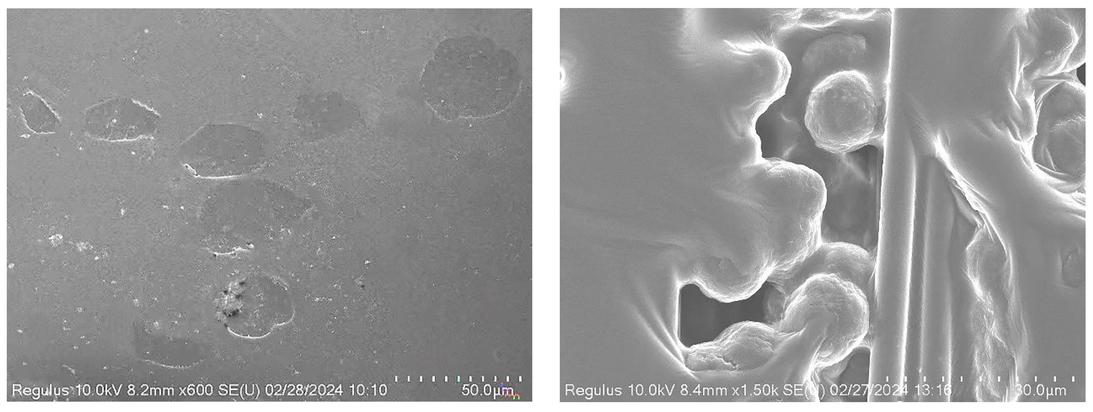
Figure 8.
Metallographic Comparison of EC2 and EC3 with and without Toughening Particles.
3.2.4. Mechanism of Particle Toughening and Compression Failure Morphology
(1) Post-Impact C-Scan Images of Carbon Fiber Composite Samples
Figure 9.
C-Scan Images of Carbon Fiber Composites After Impact and Processing Results.
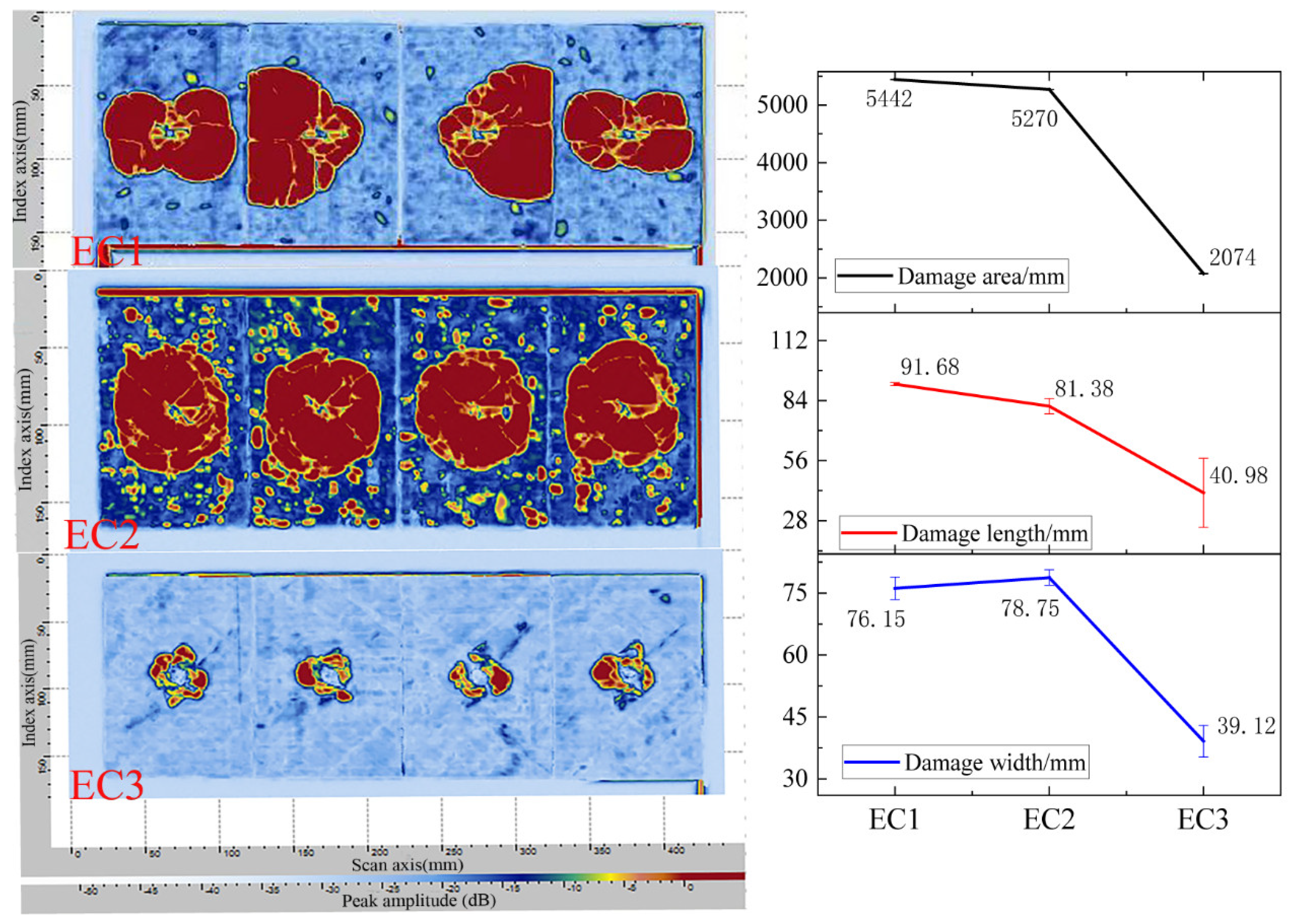
The composite material samples were prepared according to the post-impact compressive strength testing method and subjected to an impact energy of 30.15 J, followed by ultrasonic C-scan analysis, as presented in Figure 9 (a). The damage area, damage length, and damage width data are displayed in Figure 9 (b). As seen in Figure 9 (a), in the case of EC1, two of the four samples exhibited damage areas exceeding the boundary of the composite test panel following impact, indicating widespread crack propagation and substantial damage area, thus demonstrating poor impact resistance. Although the damage area for the toughened EC2 was also considerable, the impacted regions remained within the boundaries of the composite test panel, effectively restraining crack propagation. In contrast, the particle-toughened EC3 exhibited a significantly reduced damage area following impact, reflecting a marked improvement in impact performance. The data in Figure 9 (b) reveal that the damage area for EC1 was determined based on the average of the two samples exhibiting the worst damage states, while the damage area for EC3 decreased by 60.7% compared to EC2 and by 61.9% compared to EC1. The incorporation of micron-sized toughening particles significantly enhanced the impact resistance of carbon fiber composites, effectively dispersing loads and controlling crack propagation within the composite material system. This created a robust interlaminar toughening mechanism characterized by micron-sized particles.
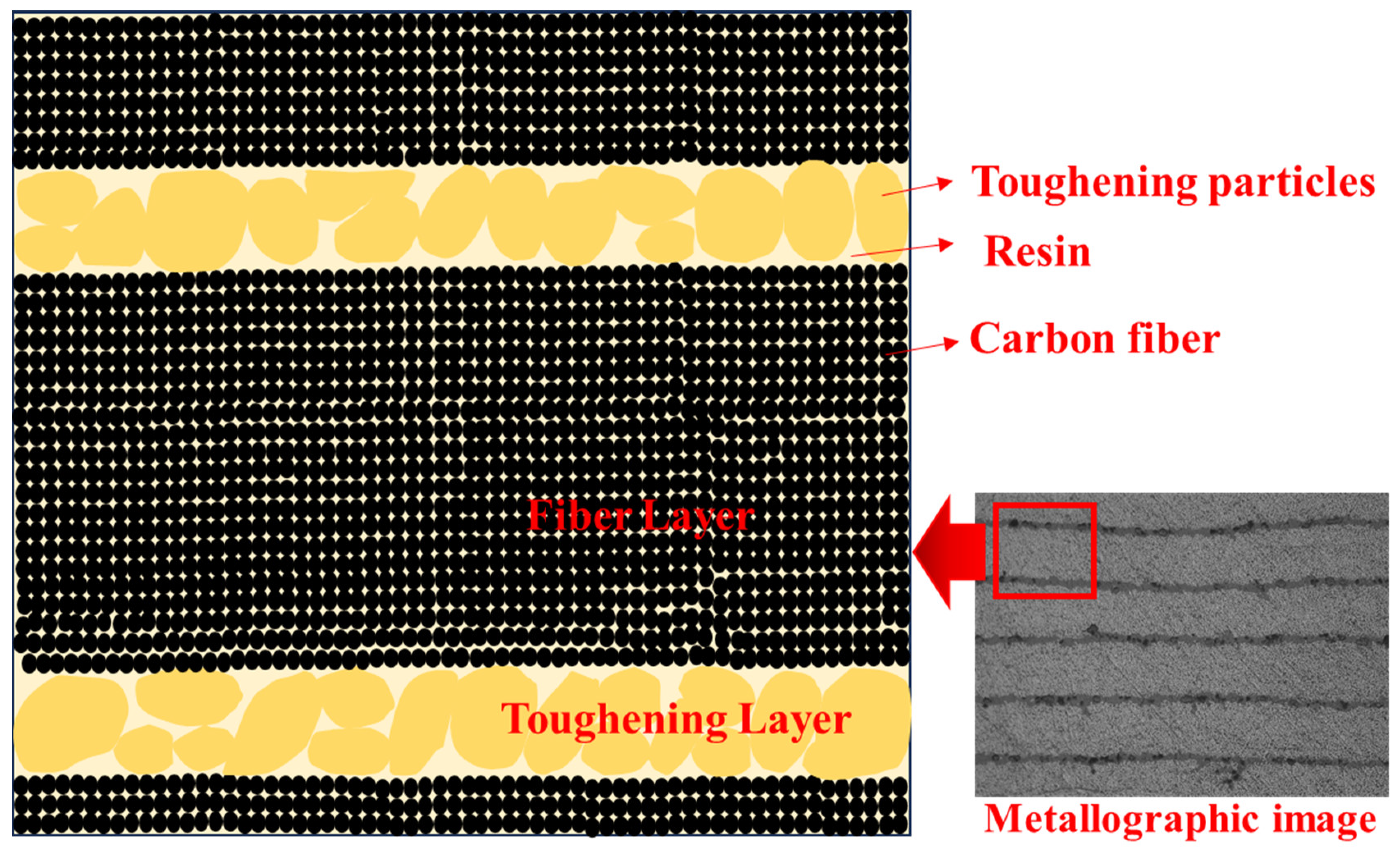
Based on the analytical results and metallographic images, a toughening model for the formation of interlaminar toughening by micron-sized particles is illustrated in Figure 10. The fiber layers and toughening layers are distinctly identified, with the resin serving as the continuous matrix phase. Both the fibers and toughening particles are distributed within the resin phase, with the toughening layers interspersed between the fiber layers. Upon application of external impact forces on the composite, the toughening layers are capable of absorbing impact energy and facilitating load transfer and dispersion, effectively inhibiting crack propagation.
Figure 10.
Model of Micron-Level Particle Interlaminar Toughened Carbon Fiber Composites.
(2) SEM Images of 0° Compression Failure
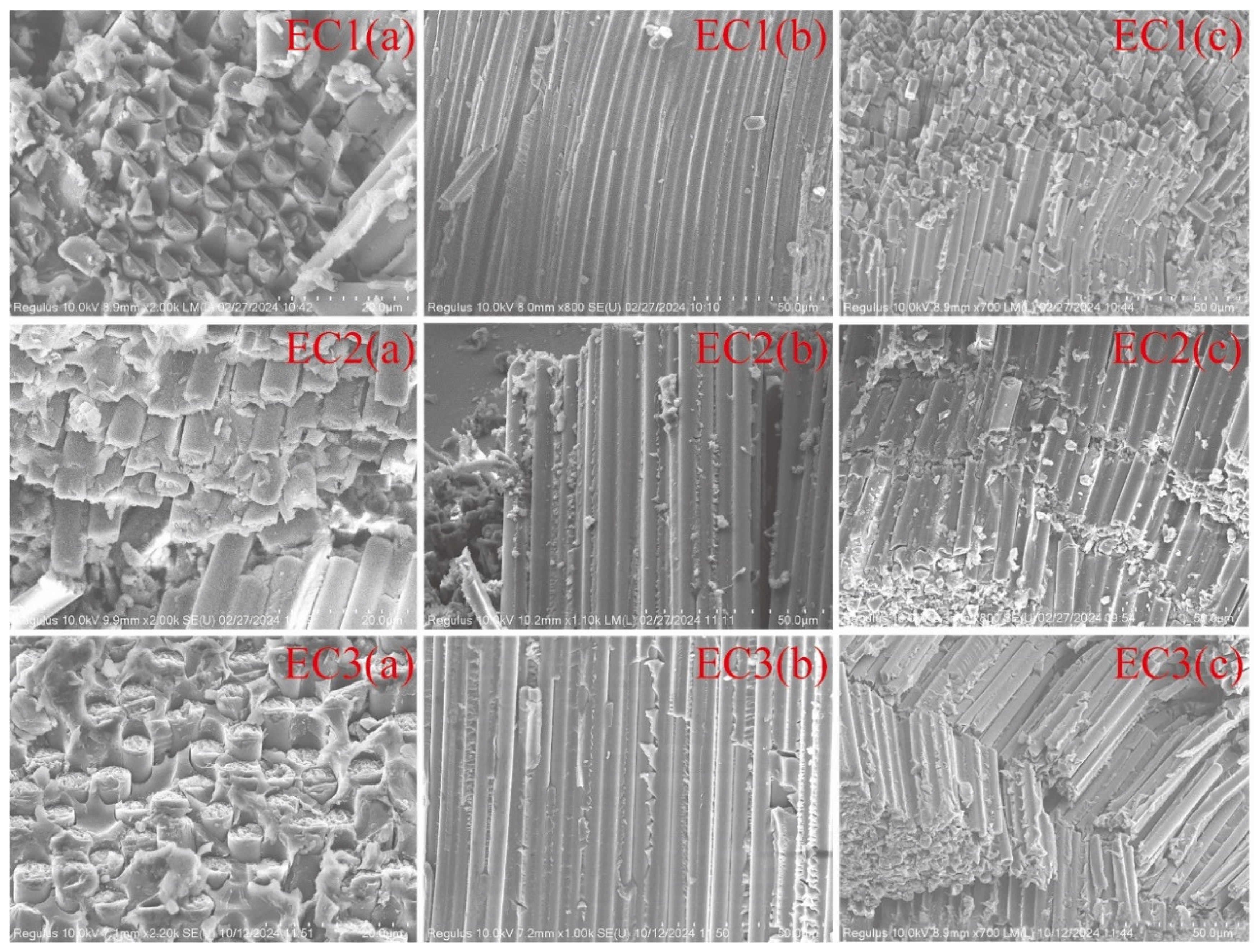
High-resolution scanning electron microscopy (SEM) analysis was conducted on the samples of carbon fiber composites that failed during the 0° compression strength test, as shown in Figure 11. Images (a), (b), and (c) represent the fracture end face, fracture cross-section, and fiber fracture morphology distribution, respectively. From Figures (a) and (b), it can be observed that the end face exhibits no significant cracks, voids, or other defects, indicating that the bonding between the fibers and the resin is satisfactory across all three sample groups. This suggests that the interfacial condition between the carbon fibers and the resin meets the fundamental requirements for carbon fiber composites, and interfacial delamination does not serve as a failure mechanism for compression fracture. Figure (c) displays characteristics of interlaminar failure, with indications of delamination present.
From the comparative analysis of the fiber distribution states after failure in carbon fiber composites, it was found that the fiber fracture state in EC1 (c) is characterized by fragmentation, with breakage occurring in small segments. This suggests that the matrix resin lacks the toughness to withstand compressive loads. Although the fibers in EC2 (c) did not exhibit fragmentation, the length of the fractured fibers increased significantly, displaying characteristics of twisting band models of fracture. This indicates that the matrix resin plays a role in load distribution under compressive loads, effectively resisting the compressive loads. In EC3 (c), features of breakage within the twisting band are evident, with fibers fracturing into longer segments, demonstrating that the toughness of the resin aids in resisting and absorbing compressive loads, leading to more distributed load-bearing by the fibers. The higher compressive strengths observed in EC2 and EC3 compared to EC1 confirm this behavior.
Figure 11.
SEM Morphology of Compression Failure in Carbon Fiber Composites.
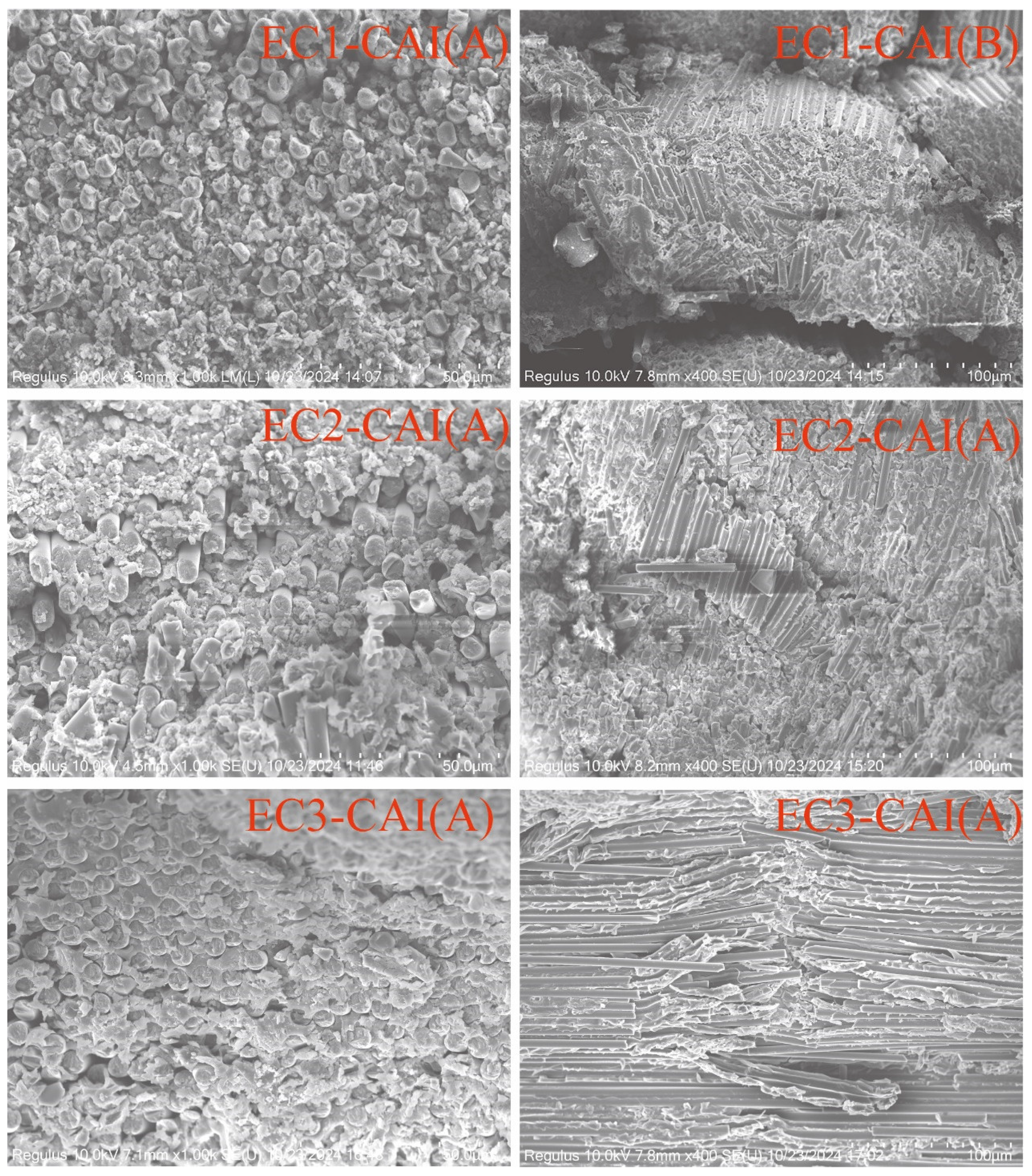
Further SEM observation of the failure morphology of samples subjected to impact and subsequent compression failure was performed. The comparison of Figure 12(A) reveals that the carbon fiber composites EC1 and EC2 exhibited significant matrix failure after being subjected to impact loads, indicating that the resin undergoes catastrophic failure under instantaneous loading conditions, resulting in concurrent fiber fracture with distinct pulverization failure characteristics. In Figure (B), it is evident that EC1 and EC2 have already experienced failure after impact loading, making them incapable of sustaining subsequent compressive loads, as evidenced by pronounced fiber breakage. However, after particle toughening, EC3 in Figure EC3-CAI(A) shows no pulverization characteristics observed in EC1 and EC2, indicating that the micron-level interlaminar toughening layer effectively absorbs and distributes the loads during impact, allowing the composite system to remain intact and continue to withstand compressive loads, characterized by twisting band failure. This further substantiates that micron-level interlaminar toughening significantly enhances the compressive after-impact performance of carbon fiber composites (CAI).
Figure 12.
CAI Failure SEM Morphology of Carbon Fiber Composites.
4. Conclusions
The introduction of a pure toughening agent into the matrix resin resulted in increases of 30% and 34% in the 0° bending strength and 0° compressive strength of carbon fiber composites, respectively. Significant enhancements were also observed in interlaminar shear strength and open-hole compressive strength, though improvements in CAI were minimal. With the incorporation of self-made micron-level toughening particles (TP), the carbon fiber composite EC3 exhibited increases of 34.8%, 67.9%, and 74.3% in interlaminar fracture toughness of Type I, interlaminar fracture toughness of Type II, and CAI, respectively, compared to EC2. It was discovered that the damage area of EC3 decreased by 60.7% relative to EC2, and the toughening effect of micron-level particles was confirmed through metallographic microscopy and SEM analysis. It was clarified that improving the compressive strength of carbon fiber composites requires addressing the performance of the resin, while enhancing the impact performance necessitates particle toughening, thereby demonstrating the reliable practical application of micron-level toughening particles in industrial settings.3.1. Subsection.
Author Contributions
For research articles with several authors, a short paragraph specifying their individual contributions must be provided. The following statements should be used “Conceptualization, KangMin Niu. and Xinfeng Ouyang; investigation, Xiao Wang.; resources, Qiufei Chen.and Yunpeng Liu; writing—original draft preparation, yangyang Zong and Shuo Duan.; supervision, Kang Lin; project administration,Guojie Ge and Dong Liu.All authors have read and agreed to the published version of the manuscript.”
Institutional Review Board Statement
This study does not involve humans or animals, therefore 'Not applicable'.
Acknowledgments
Thank Zhongfu Shenying Carbon Fiber Co., Ltd. for providing experimental raw materials and assistance with related testing. Thank you to the Jiangsu Industrial Technology Research Institute for your support in this research.
Conflicts of Interest
The authors declare no conflict of interest. The co-author from Zhongfu Shenying Carbon Fiber Co., Ltd. contributed to the article by providing experimental assistance, data analysis, paper revision, and other related contributions.
References
- He Fu. Carbon Fibers and Graphite Fibers. Beijing: Chemical Industry Press. 2010.
- LIU Liuxin, LU Xiaoying, WU Ying, LI Shuanhong, WU Jinyu, YUAN Wenjing, GAO Yuan. Progress in interface modification and application of carbon fiber reinforced resin matrix composites[J]. Journal of Materials Engineering, 2024, 52(9): 70-81 . [CrossRef]
- N. Domun , H. Hadavinia , T. Zhang, T. Sainsbury , G. H. Liaghat and S. Vahid .Improving the fracture toughness and the strength of epoxy using nanomaterials-a review of the current status[J]. (Review Article) Nanoscale, 2015,7, 10294-10329. [CrossRef]
- China National Building Materials Group: With the Ambition of Serving the Country's Great Interests, Boldly Shouldering the Country's Important Responsibilities, and Forging the Country's Premium Materials [J]. China Building Materials, 2024, (10): 32-36.
- Zheng Yaping. Research on High-Modulus Resin Matrix and High-Compressive Strength Composites [D]. Xi'an: Northwestern Polytechnical University, 2001.
- Liu Bangxiong. Research on the Damaged Mechanism in Low-velocity Impact and Compressive Residual Strength of Stitched Carbon Fiber Composite Laminates [D]. Nanchang University,2024. [CrossRef]
- Tian Jing. Studies on Low-velocity Impact Damage of Stitched Composite Laminates [D]. Studies on Low-velocity Impact Damage of Stitched Composite Laminates,2008.
- YAO Jiawei, FENG Ruixuan, NIU Yifan, et al. Research progress of the interleaved thermoset composites by carbon nanomaterials/thermoplastic resin[J]. Acta Materiae Compositae Sinica, 2022, 39(2): 528-543. [CrossRef]
- Latif Zeeshan,Ali Mumtaz,Lee Eui-JongZubair ZakariyaLee Kang HoonTornabene Francesco.Thermal and Mechanical Properties of Nano-Carbon-Reinforced Polymeric Nanocomposites: A Review[J].journal of composites science,2023,7(10).
- JIANG Cai, CHE Zhe, XING Fei, et al. Research progress on interlaminar property of carbon nanotube-continuous fiber reinforced resin matrix composites[J]. Acta Materiae Compositae Sinica, 2022, 39(3): 863-883.
- Hsieh T H , Kinloch A J , Masania K ,et al.The toughness of epoxy polymers and fibre composites modified with rubber microparticles and silica nanoparticles[J].Journal of Materials Science, 2010, 45(5):1193-1210. [CrossRef]
- Xiao Tian.The study of core-shell toughened multi-functional epoxy resin and its carbon fiber composite[D].Beijing University of Chemical Technology,2012. [CrossRef]
- Phong N T , Gabr M H , Anh L H ,et al.Improved fracture toughness and fatigue life of carbon fiber reinforced epoxy composite due to incorporation of rubber nanoparticles[J].Journal of Materials Science, 2013, 48(17):6039-6047. [CrossRef]
- A K L K , B G P S , A P A L ,et al.Improved fracture toughness of carbon fiber composite functionalized with multi walled carbon nanotubes[J].Carbon, 2008, 46( 15):2026-2033. [CrossRef]
- P,Karapappas,A,et al.Enhanced Fracture Properties of Carbon Reinforced Composites by the Addition of Multi-Wall Carbon Nanotubes[J].Journal of Composite Materials, 2009, 43(9). [CrossRef]
- Elisa B , Eslam S , Usama K ,et al.Interlaminar Fracture Toughness of CFRP Laminates Incorporating Multi-Walled Carbon Nanotubes[J].Polymers, 2015, 7(6):1020-1045. [CrossRef]
- ZHAO Hongchen, OU Yunfu, WU Longqiang, et al. Preparation and toughening mechanism of glass fiber/epoxy composites toughened by carbon nanotube sprayed layers[J]. Acta Materiae Compositae Sinica, 2024, 41(5): 2364-2373. [CrossRef]
- WU Longqiang, OU Yunfu, MAO Dongsheng, et al. Interlaminar properties and toughening mechanisms of aligned carbon nanotube fiber veil interleaved carbon fiber/epoxy composites[J]. Acta Materiae Compositae Sinica, 2023, 40(10): 5611-5620. [CrossRef]
- Yang Z X, Chai Z H, Jin Z H, et al. Analysis of impact resistance of graphite reinforced carbon fiber composites[J]. Plastics Science and Technology, 2023, 51(8): 48-53. [CrossRef]
- Hu Tao, Zhao Donglin, Cheng Xingwang, et al. Study on the Preparation and Mechanical Properties of Graphene Oxide Reinforced Epoxy Resin Composites [J]. Journal of Beijing University of Chemical Technology (Natural Science Edition), 2018, 45(06): 29-33. [CrossRef]
- Kim Seong-Hwang,Park Soo-Jin.Effect of graphene oxide/graphitic nanofiber nanohybrids on interfacial properties and fracture toughness of carbon fibers-reinforced epoxy matrix composites[J].Composites, Part B. Engineering,2021,227(15):109387.1-109387.9.
- DAI Shaowei, ZHOU Yujing, LI Weidong, et al. Interlaminar toughening of carbon fiber/epoxy composites with graphene oxide-carbon nanotube composite film[J]. Acta Materiae Compositae Sinica, 2023, 40(7): 3862-3873. [CrossRef]
- Rodriguez-Garcia V , Gomez J , Cristiano F ,et al.Industrial manufacturing and characterization of multiscale CFRP laminates made from prepregs containing graphene-related materials[J].Materials Research Express, 2020. [CrossRef]
- ] Zeng Qingyang. Study on the Interlaminar Toughening of Carbon Fiber Composites through Synergistic Effects of Micro- and Nano-particles [D]. Beijing University of Chemical Technology, 2018. DOI: CNKI:CDMD:2.1018.323795.
- Yibiao Wan, Jiamei Lai, Peixi He, et al. Effect of Modification with Inorganic Micro- and Nano-particles on the Mechanical Properties of Carbon Fiber Composites [J]. Polymer Materials Science and Engineering, 2021. [CrossRef]
- Zhao Junshuai. Preparation and Properties of Nano-clay/Carbon Modified Carbon Fiber/Epoxy Resin Composites [D]. Hefei University of Technology, 2018. DOI: CNKI:CDMD:2.1018.222616.
- Mingyan Zhang, Mingchuan Li, Chengzhi Zhou, et al. Effect of Montmorillonite and Carbon Nanotubes on the Mechanical and Thermal Properties of Epoxy Composites [J]. Polymer Materials Science and Engineering, 2015, 31(6): 116-121.
- Wang Zhenyu, Li Jianhua, Guo Huijun, et al. In-situ Synthesis of Nano-SiO2 Reinforced Anionic Polyester-based Sizing Agent and Its Effect on the Interlaminar Shear Strength of Carbon Fiber Composites [J]. Chemical Journal of Chinese Universities, 2019, 40(9): 7. [CrossRef]
- Jiang Zhenyu, Zhang Hui, Liu Sheng, et al. Improved Interfacial Bonding of Carbon Fiber/Epoxy Matrix Modified by Wel-l Dispersed Nano-SiO2 Particles, 2007, 22(3): 8. [CrossRef]
- Fang Yixin, Chen Wei, Jiang Zhenyu, et al. Compressive Performance of Multi-phase Reinforced Epoxy Composites with Carbon Fibers and Nano SiO₂ [J]. Acta Materialiae Compositae Sinica, 2019, 36(6): 1343-1352.
- Chen Yonglong. Study on Preparation and Properties of Nano-SiO2 and Short Carbon Fiber Reinforced Epoxy-Bismaleimide Composites [D]. Southwest University of Science and Technology, 2015.
- Zhang Yingchen, Zou Jing, Wu Hongyan, et al. Method for Surface Modification of Carbon Fibers Coated with Nano-Silicon Dioxide by Plasma Treatment [P]. Shanghai, China: CN200810202621.2, Published on August 31, 2011.
- Liu Baiyang. The Study of Preparation and Reinforcing Effect of Silica Nanoparticle-MWCNT Hybrid Reinforcement on CFRP [D]. Beijing University of Chemical Technology, 2013.
- Zheng Nan. A Study on Nano-Phase Interlaminar Toughening of Carbon Fiber/Epoxy Composites [D]. Harbin Institute of Technology, 2017.
- LIU Xin, CHEN Duo, HE Huiyong, et al. Synergistic toughening of thermoplastic particles-inorganic particles to carbon fiber reinforced epoxy resin composites[J]. Acta Materiae Compositae Sinica, 2020, 37(8): 1904-1910. [CrossRef]
- YAO Jiawei, LIU Mengyao, NIU Yifan. Mechanical properties of PEK-C interlayer toughened carbon fiber/epoxy composites[J]. Acta Materiae Compositae Sinica, 2019, 36(5): 1083-1091. [CrossRef]
- Ma, Y.; Zhao, W.; Xiong, J.; Zhang, W.; Dai, M.; Guo, Y.; Li, Y.; Long, L.; Zhou, Z. Hierarchical Interfacial Construction by Grafting Cellulose Nanocrystals onto Carbon Fiber for Improving the Mechanical Performance of Epoxy Composites. Nanomaterials 2024, 14, 1537. [CrossRef]
- Ning Na. Core/Shell Nanoparticles – Their Synthesis and Use for Epoxy Resin and Carbon Fiber Composite Toughening [D]. Donghua University, 2022.
- Liu Dawei. Study on the Mechanism of Micro/Nanoparticle Synergistic Reinforcement and Toughening in Carbon Fiber Composites [D]. Beijing University of Chemical Technology, 2016. [CrossRef]
Disclaimer/Publisher’s Note: The statements, opinions and data contained in all publications are solely those of the individual author(s) and contributor(s) and not of MDPI and/or the editor(s). MDPI and/or the editor(s) disclaim responsibility for any injury to people or property resulting from any ideas, methods, instructions or products referred to in the content. |
© 2024 by the authors. Licensee MDPI, Basel, Switzerland. This article is an open access article distributed under the terms and conditions of the Creative Commons Attribution (CC BY) license (http://creativecommons.org/licenses/by/4.0/).
Copyright: This open access article is published under a Creative Commons CC BY 4.0 license, which permit the free download, distribution, and reuse, provided that the author and preprint are cited in any reuse.


