Preprint
Article

This version is not peer-reviewed.

In-Situ Synthesis of Porous SnO2/SnS2@PC Anode Material with High-Capacity Using Calcium Carbonate as Template for Lithium-Ion Batteries

  † These authors contributed equally to this work.

A peer-reviewed article of this preprint also exists.

Submitted:

18 September 2025

Posted:

19 September 2025

You are already at the latest version

Abstract

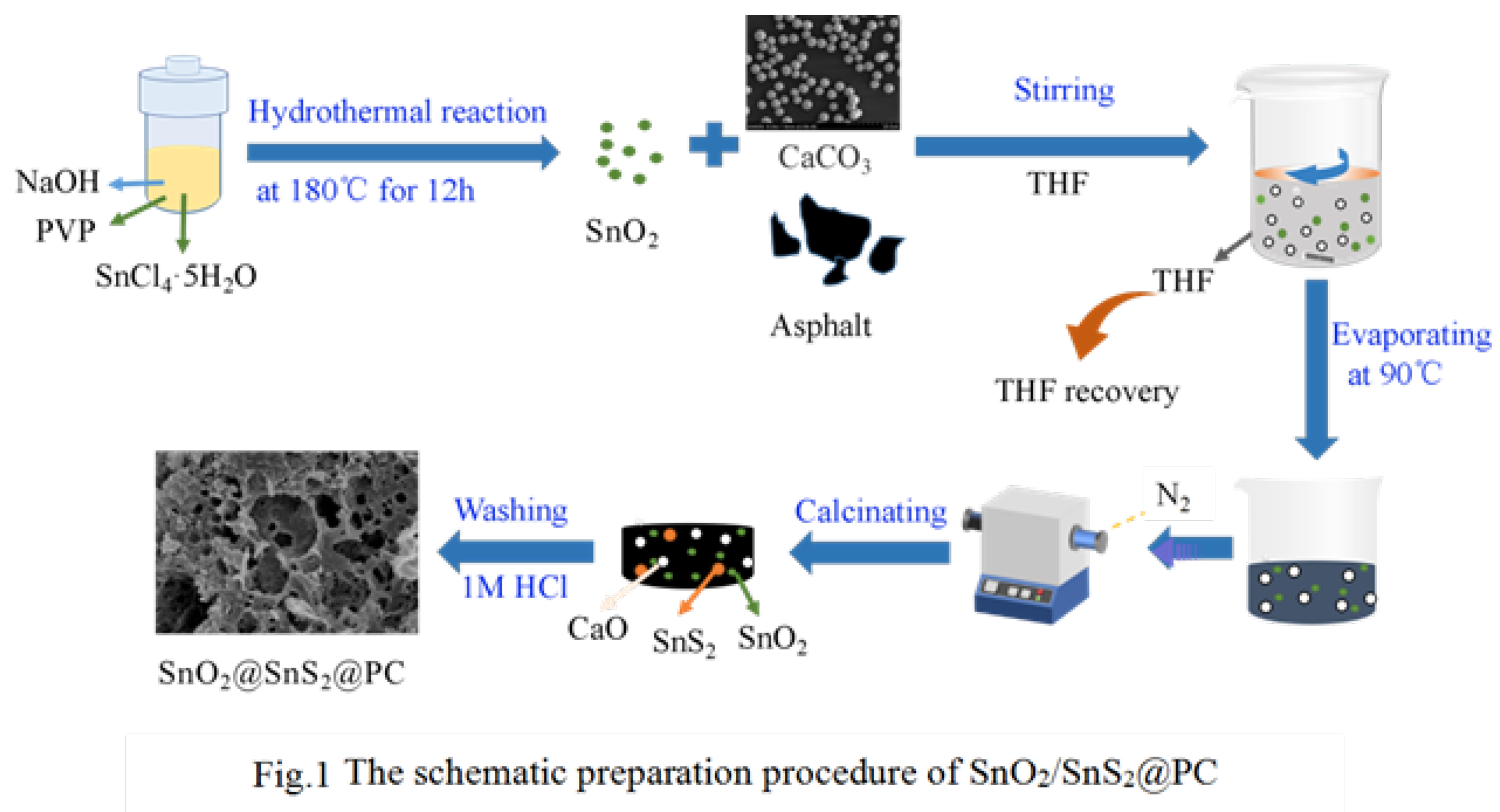
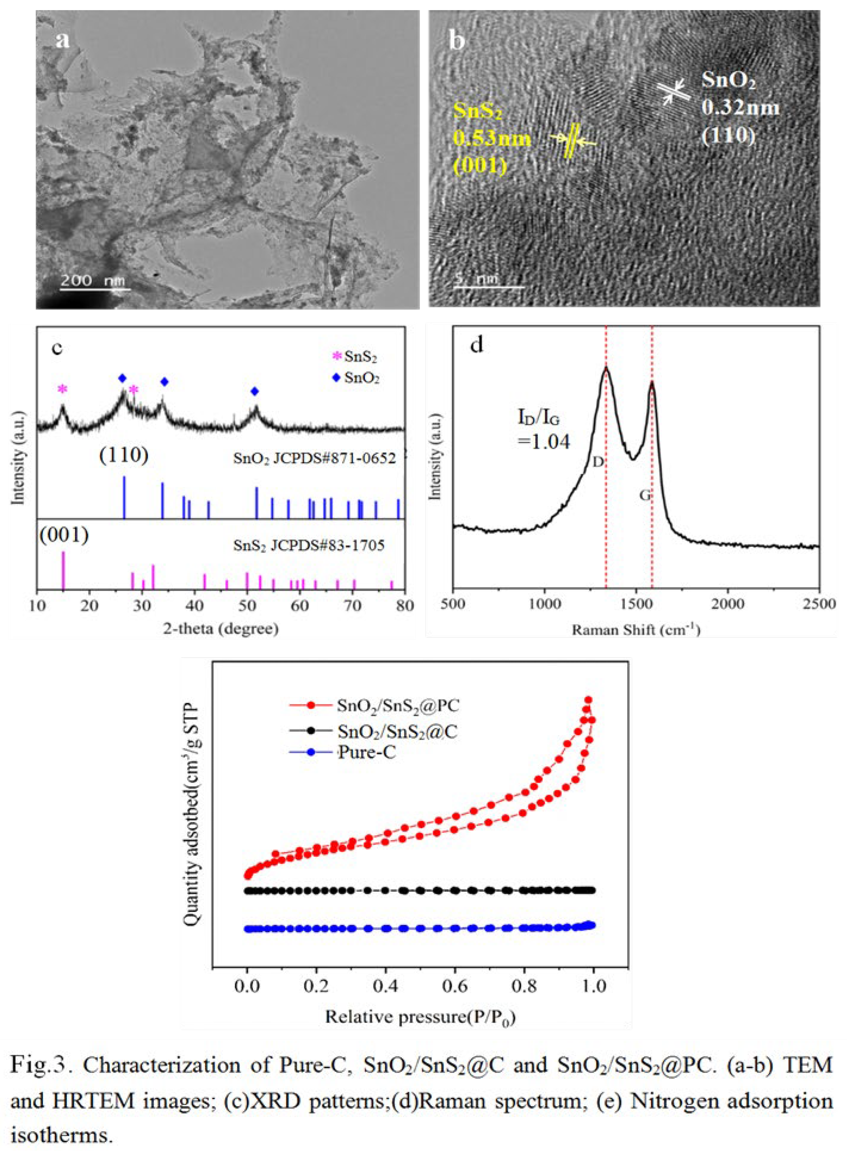
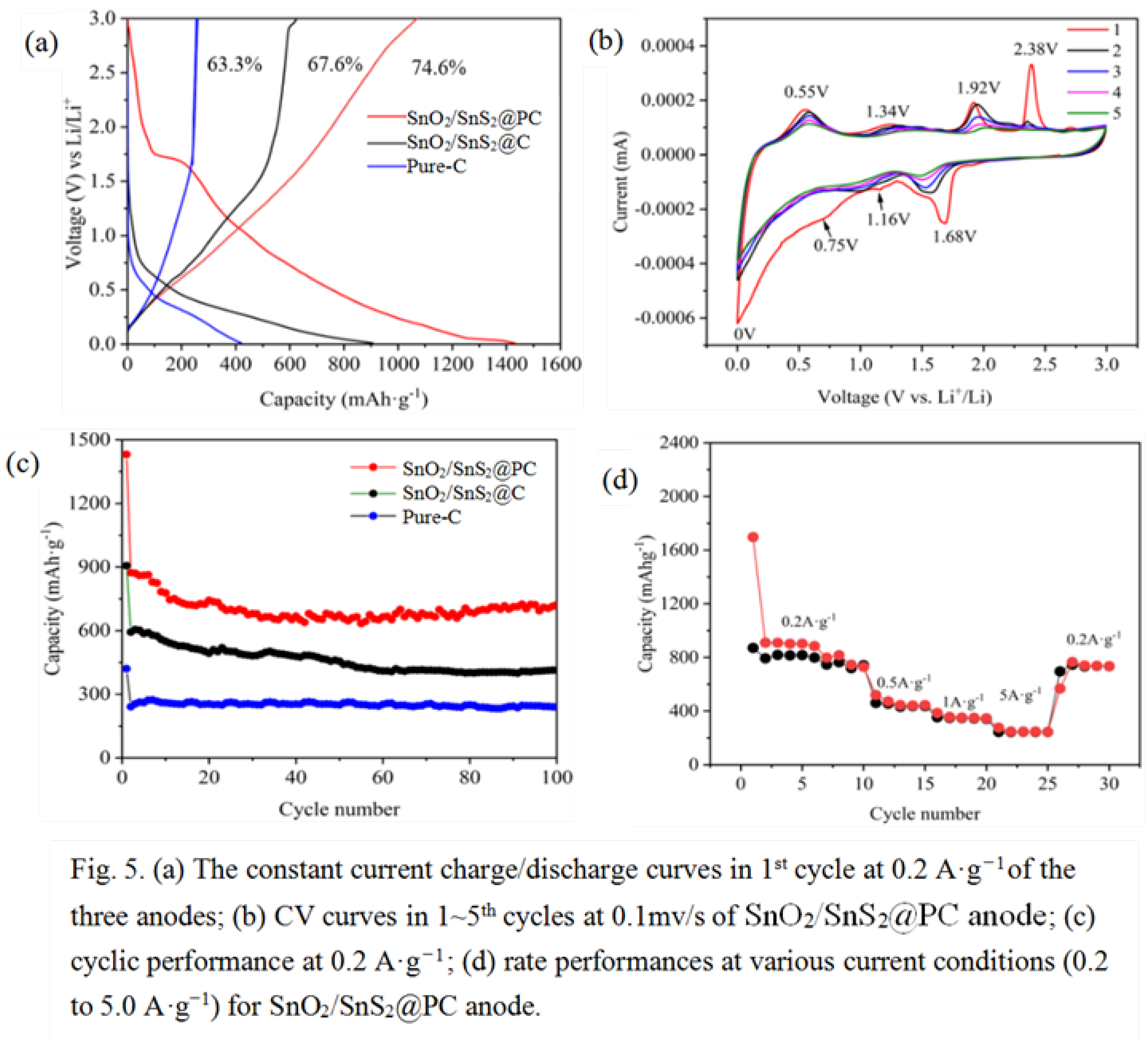
Tin-based materials have emerged as promising anode candidates for advanced lithium-ion batteries(LIBs) due to their high theoretical capacity (e.g. 994 mAh/g for Li₄.₄Sn), moderate operating potential, and natural abundance. However, Tin-based materials suffer from severe volumeexpansion (>300%) and rapid capacity during cycling. In this work, a composite composed of tin-based materials and porous carbon (PC), i.e. SnO2/SnS2@PC, was in-situ synthesized to mitigate these challenges. The composite was obtained by high-temperature calcination of a mixture containing SnO2, pe troleum asphalt and calcium carbonate, where petroleum asphalt acted as the carbon and sulfur resource, calcium carbonate acted as a pore-forming template. The prepared SnO2/SnS2@PC composite possed a specific surface area of 190.5 m2·g-1 with total pore volume 0.386 cm3·g-1, and delivered an initial specific capacity of 1431 mAh·g-1 and retained 722 mAh·g-1 at 100th cycle at 0.2 A·g−1, which is nearly three folds that of the actual capacity(~260 mAh/g) of commercial graphite and thus shows a promising application in next-generation LIBs.

Keywords: 
;  ;  ;  ;  

1. Introduction

Nowadays, Lithium-ion batteries(LIBs) are the preferred power source for electric- vehicles, grid storage and portable electronic device ascribed to their large voltage window, high energy density and conversion efficiencies, reasonable life spans, and safety [1,2]. For consumers, especially those who own electric vehicles, the duration of continuous use after a single charge is a matter of great concern. This directly depends on the capacity of a battery, which is determined by the specific capacity of the electrode materials used in the battery(includes cathode material and anode material). With regard to the anode material of LIBs, graphite remains the commercially dominant choice, owing to its excellent conductivity, stable layered structure, low cost, and mature industrializa- tion technology, but it cannot meet the criteria for emerging high-end applications in commercial markets attributing to its inferior theoretical specific capacity(372 mAh/g). Furthermore, the dendritic lithium deposition at low potential over graphite can decline the performance and affect safety issues [3,4].
To develop alternative anode materials with higher capacity, over the last decade or so, the graphite-alternative anode materials such as silicon-based materials [5], black phosphorus [6], transition metal oxides and sulfides [7,8,9,10,11,12,13,14,15], lithium titanite oxide(LTO)[16], have attracted widespread attention due to their higher specific capacity or superior rate performance. Among these candidate materials, Tin-based materials are deemed as the most potential alternatives owing to their advantages of low voltage, high theoretical specific capacity(e.g., 994 mAh/g for Li4.4Sn) and relatively rich abundance. However, there are several obstacles restricting their wholesale applications, such as the severe specific volume variation in conversion-reaction during charge/discharge process, which resulting in structural instability (pulverization) and rapid capacity decline at high-rate condition, and their poor electrical conductivity [17]. To solve these issues, the integration of Tin-base materials with carbon with specific structural carbon is an effective approach. The commonly applied carbonaceous materials are graphite, graphene, carbon nanotubes (CNTs), carbon nanofibers (CNF)[18,19]. The incorporated carbon materials has the able of improve the electrical conductivity, reduce the particle agglomeration and effectively restrain the volume expansion of the particles due to the layered or porous structure, which provides a buffer space for volume expansion, thereby improving the electrochemical performance of the hybrid materials. For example, Choi et.al synthesized a SnO2/nano-perforated graphene composite by conversion reaction of Sn and Li2O to SnO2, and displayed a initial capacity of 1446 mAh·g−1 at the current density of 100 mAh·g−1[8]. Li et.al fabricated a SnO2/SnS2@carbon/N-doped(SnO2-SnS2@C/NG) composite by using SnCl4, sodium alginate, reduced graphene and thioacetamide as start materials, this composite showed a high initial capacity of 1201.2 mAh·g−1 at the current density of 100 mA·g−1[9]. Syum et.al prepared a SnS2-CNT-CC anode material with a capacity of 645 mAh·g−1 after 100 cycles [10]. Cheng et.al reported an SnS2/CNTs composite, which showed a capacity of 660 mAh·g−1 after 100 cycles [11]. Jin et.al synthesized a SnS2/SnO2@C/rGO nanocomposite by using SnCl2, thiourea, L-ascorbic acid and graphene oxide(GO) as reactants, which exhibited a reversible capacity of 689 mAh·g−1 at a current density of 78.3 mA·g−1[12]. These Tin-based hybrids show an significantly improved in capacity compar ing with graphite, but these materials all utilized expensive graphene or CNTs.
Porous carbon has the advantages of high conductivity, stability, surface area and low cost, which can be prepared via in-situ templating synthesis [20]. The cheap carbon sources for preparing porous carbon mainly include bitumen (petroleum bitumen and coal tar pitch) and biomass [21,22,23]. Some thermally unstable chemical compounds such as citrates, oxalates, acetates, and basic carbonates, are the most widtely used templates [24]. The extremely cheap calcium carbonate(CaCO3) also can be used as a pore-forming template, it is decomposed to calcium oxide (CaO) and carbon dioxide (CO2) at over 700 ℃ [25]. Although the decomposition temperature is higher, it is conducive to the graphitization of carbon, which is essential for porous carbon as an anode material.
Petroleum asphalt is a very abundant and cheap carbon material for producing porous carbon, it is a black-brown mixture of polycyclic aromatic hydrocarbons of different molecular weights and their non-metallic derivatives [21]. In this study, we fabricated a porous SnO2/SnS2@PC anode material by using SnCl4 and petroleum asphalt as starting materials, CaCO3 as the pore-forming template. The petroleum asphalt contains a certain amount of S element, which can reacted with part of the SnO2 and converted to SnS2 in the pyrolysis process and finally in-situ formed porous SnO2/SnS2@PC composite, which delivered an initial specific capacity of 1431 mAh·g−1 at 0.2 A·g−1 and retained ~722 mAh·g−1 at100th cycle, showing a significant improvement in capacity comparing with graphite.

2. Materials and Methods

2.1. Chemicals

Petroleum asphalt was purchased from China Petroleum & Chemical Corporation. The CaCO3 with a spherical shape and ~3 μm in size was synthesized by our group through the reaction of Na2CO3(0.1 M) with CaCl2(0.1 M). All other reagents were analytical grade and used without further purification. Ultrapure water was obtained through reverse osmosis membranes(electrical resistivity is 18.2 MΩ.cm) and was used for making all aqua solutions.

2.2. Synthesis of SnO2/SnS2@PC Composite

(1)Synthesis of nano-SnO2. The nano-SnO2 was synthesized by hydrothermal method. In brief, 1.40 g SnCl4·5H2O, 0.1.20 g NaOH, and 0.3 g PVP were dissolved in a 30 mL ethanol-water (1:1) solution and continuously stirred magnetically until transparent. Next, Then the solution was transferred into a 100 mL Teflon-lined stainless autoclave and maintained temperature in a hot air oven at 180℃ for 12 h. After cooling to room temperature, the final product(nano-SnO2) was centrifuged and washed three times with water. After drying under vacuum at 80℃for 12 h, the obtained white powder was fully ground and stored for later use.
(2)Synthesis of SnO2/SnS2@PC composite. First, 50mL of tetrahydrofuran(THF) and 7.5 g of asphalt was added to a 100mL beaker and stir until completely dissolved. Then, added 0.5 g SnO2, and 2 g CaCO3 into the solution and continue to stir for 30 minutes. Next, the mixture was placed in a 90℃water bath for heating to recover THF. The resultant was transferred to a ceramic crucible and put in a tube furnace to calcine under 900℃ for 2 h in the nitrogen atmosphere. After natural cooling, the calcined residue was alternately washed with 1 M HCl solution and pure water three times to remove the CaO produced by the decomposi tion of CaCO3 and finally dried in a vacuum oven at 80 ℃, the obtained product was denoted as SnO2/SnS2@PC, where, the SnS2 was formed by the combination of sulfur elements in asphalt and Sn in SnO2, which can be confirmed by the analysis results of XRD and XPS. For comparison, the SnO2/SnS2@C and pure carbon samples were prepared in the absence of CaCO3 or SnO2 and CaCO3 under the same conditions, respectively. The schematic procedure preparation of SnO2/SnS2@PC is illustrated in Figure 1.

2.2. Characterization

The SEM and observations were performed by TESCAN MIRA LMS (Czech) and Tecnai G2 F30(FEI Tecnai F20, U.S.A) respectively. The Powder X-ray diffraction(XRD) analysis was carried out in a X-ray diffractometer (Bruke D8, Germany) with Cu Kα radiation (λ=0.1540 nm) at 2θ from 10 to 90°. The X-ray photoelectron spectroscopy(XPS) was conducted on a Thermo Scientific K-Alpha spectrometer (U.S.A) using C 1s (284.8eV) as a reference. Raman spectra were recorded on a Raman spectrometer (WIT ecalpha300R,Germany) with an excitation wa velength of 532 nm. Nitrogen adsorption/desorption isotherms were recorded on a Micromeritics instrument(ASAP 2460, U.S.A).

2.3. Electrochemical Measurements

All electrochemical tests were conducted using a CR2025 coin-type cell, in which, the working electrode and anode were the as-synthesized active material and lithium foil respectively, polypropylene microporous membrane (Celgand 2400) was used as aseparator, the electrolyte was 1M LiPF6 dissolved in EC/DMC/EMC (1:1:1, v/v/v). The preparation of the working electrode included the following steps: 0.8 g active material,0.1 g acetylene black, and 0.1 g polyvinylidene fluoride (PVDF) were mixed with 5 ml of 1-methyl pyrrolidone (NMP) and magnetically stirred for 6 hours to form a slurry. The slurry was then coated on Cu foil and dried in a vacuum oven at 80 °C for 8 h. After that, the copper foil was punched into discs with a diameter of 14.0 mm, on which the average active materials loading was about 1.1± 0.05 mg cm−2. The assembled CR2025 cells were assembled in an argon-filled glove box and tested after stand ing for 8 h. The galvanostatic charge/discharge tests were carried out in a battery measurement system(LAND CT2001A, Wuhan, China) in a 0.01−3.0 V voltage range vs. Li+/Li. Cyclic voltammetry (CV) and electrochemical impedance spectroscopy (EIS) tests were performed in an electrochemical working station(CHI660E, Shanghai, China). The CV curves were moni- tored at a scanning rate of 0.1 mV·s−1 within a voltage 100 kHz with an AC potential amplitude of 5 mV. All electrochemical measurements were conducted at 25 ±1 ℃

3. Results

Figure 2a-c show the SEM images of the prepared Pure-C, SnO2/SnS2@C, and SnO2/SnS2@PC composites. As displayed in Figure 2a and 2b, the particle morphology of Pure-C and SnO2/SnS2@C presented layered structure and no pores were observed, some nano particles(SnO2 and SnS2) were attached to the surface of carbon matrix. Different from these two composites, the SnO2/SnS2@PC composite possess a three-dimensional(3D) porous structure which constructed from carbon nanosheets with lots of open mesopores of 30~200 nm as depicted in Figure 2c, the large pores can be reasonably inferred to have been formed by the escape of CO2 gas and the small pores were formed by the dissolve of CaO existing within in the composite, both CO2 and CaO were the de composition products of CaCO3 at high temperature. Additionally, the elemental distribution and content of C, O, S, and Sn in SnO2/SnS2@PC was probed by energy-dispersive X-ray spectroscopy(EDS). The mapping images shown in Figure 2d-h reveal that the C, O, S, and Sn elements were evenly scattered all over the carbon matrix, and the molar ratio of SnO2 to SnS2 is estimated to be 7/3 according to the atom percentage of O, S, and Sn as shown in the inset table of Figure 2i.
The TEM image(Figure 3a) of SnO2/SnS2@PC shows that many extremely tiny SnO2 and SnS2 nano-spherical particles were incorporated with the porous sheet-like carbon skeleton matrix. The HR-TEM image(Figure 3b) indicates the lattice stripes of (110) crystal planes of SnO2 and (100) crystal planes of SnS2 are 0.32 nm and 0.53 nm respectively. The XRD pattern of the SnO2/SnS2@PC composite is illustrated in Figure 3c, the main characteristic peaks of SnO2 and SnS2 are simultaneously appeared, confirming that both SnO2 and SnS2 were presented in the composite, where the SnS2 was conversed by reaction of partial SnO2 with S element existing in asphalt during the high-temperature calcination process. The strongest peak at 26.6°(110) and two other major diffraction peaks at 33.9°(101), and 51.7° (211) can be clearly seen, corresponding to tetragonal phase of SnO2 (JCPDS 41-1445) with spatial group of P42/mnm. The strongest characteristic peaks at 15.1° aligns with the crysta llographic diffraction peak of SnS2 of the (001) , this is the primary basis for determining its existence, the peaks at 28.2°, 32.1° index to (100) and (101) crystal planes, matching the hexagonal phase of SnS2 (JCPDS 23-0677) with spatial group of P-3m1[8,9,10,11].
The Raman spectroscopy was conducted to characterize the structure of carbon material in SnO2/SnS2@PC composite. As shown in Figure 3d, both the D-band located at 1350 cm-1 and G-band located at 1580 cm-1 are clearly visible, the appearance of D-band derived from the carbon six-membered ring indicates that there were defects, disorders or boundaries in the graphite lattice, while the G band caused by the in-plane stretching vibration of the sp2 hybrid orbitals of carbon atoms reveals the existence of an ordered graphitized structure in the ample [26,27]. The degree of defects in the porous carbon can be evaluated by the intensity ratio (ID/IG), which is calculated to be approximately 1.04, suggesting that the degree of defects is slightly higher than that of the degree of graphiti- zation of the prepared porous carbon. The textural properties of the three samples were studied using nitrogen adsorption/desorption isotherm analyses as presented in Figure 3e. The isotherm of SnO2/SnS2@PC consists of an apparent hysteresis (H4) loop which was detected within the relative pressure(P/Po) region of ~0.3 to 1.0, vesting in type IV gas sorption characteristics according to the IUPAC classification, reflecting their mesoporous structure [23,28]. Moreover, the N2 adsorbed quantity increases sharply at relatively high pressure(P/P0 close to 1), which is caused by large pores [29,30], this in accordance with SEM observation shown in Figure 2a and 2b. For comparison, the nitrogen adsorption isoth- erms of pure C and SnO2/SnS2@C display very limited nitrogen adsorption capacity, confirming their nonporous structure. The specific sur face area(STotal) and total pore volume(VTotal) are calculated as 190.5 m2·g−1(Brunauer-Emmett-Teller, BET) and 0.386 cm3·g−1(Barrett-Joyner-Halenda, BJH), respectively. Both the specific surface area and pore volume are superior to those of Pure-C(2.3 m2·g−1, 0.001 cm3·g−1) and SnO2/SnS2@C(3.0 m2· g−1, 0.005 cm3·g−1 ) .The significant increases in specific surface area and total pore volume for SnO2/SnS2@PC are attribute to the results of CO2 escaping and CaO being dissolved by hydrochloric acid to form a porous structure, both of CO2 and CaO are products of the decomposition of CaCO3 at high temperatures. The specific surface area and pore struc- ture parameters are accordingly calculated and listed in Table 1. By comparing the specific surface areas of micropores(SMic), mesopores(SMec) and pore volumes of macro- pores (VMac), mesopores(VMec) , we can draw the conclusion that the presence of mesopores makes the predominant contribution to the total surface area and total pore volume
The chemical composition and electronic state of the composite surface were analyzed by XPS. Figure 4a displays the survey spectrum of SnO2/SnS2@PC composite, confirming the presence of four elements of C, O, S, and Sn. Figure 4(b-e) display the high-resolution XPS spectra of C 1s, O1s, S 2p and Sn 3d. The peaks located at a binding energy of 284.8, 285.2, and 286.1 eV in C 1s spectrum (Figure 4b) are attributed to C−C, C−S, and C−O respectively [31]. The peaks at the energy of 530.5 eV and 532 eV in the O 1s spectrum (Figure 4c) are as scribed to Sn−O−Sn and C−O−Sn bond respectively, and validates the valence state of O is -2[32,33]. Figure 4d represents the deconvoluted S 2p spectrum, the peak located at a binding energy of 162.1 eV(S 2P3/2) assigns to the S‒S bond, the peak at 163.3 eV(S 2P3/2) is specified metal-S bonding, and the peak located at 164.9 eV(S 2P1/2) belongs to S-C covalent bond [34,35]. The two peaks located at a binding energy of 487.2 eV and 495.6 eV (Figure 4e) belong to Sn 3 d5/2 and Sn 3 d3/2, respectively, the splitting energy between Sn 3d5/2 and Sn 3d3/2 is 8.4 eV, such a Sn 3d spectrum designates the Sn4+ state [36]. The results of XPS analysis demonstrate that both SnO2, SnS2 were present in the SnO2/SnS2@PC composite, which consistent with the XRD analysis results.

Electrochemical Properties of SnO2/SnS2@PC Composite

The Li-ion storage outcomes of Pure-C, SnO2/SnS2@C and SnO2/SnS2@PC as LIB anodes were evaluated using the CR-2025 coin cell assembly vs. Li metal. Figure 5a presents the galvanostatic charge/discharge (GCD) profiles for the first cycle captured at a current density of 0.2 A·g−1. As is shown, the initial charge/discharge specific capacity were determined to be 1068/1431 mAh·g-1 (SnO2/SnS2@PC), 613/906 mAh·g-1(SnO2/SnS2@C), and 266/421 mAh·g-1(Pure-C), with the initial Coulomb efficiency(CE) of 74.6%, 67.7%, and 63.2%, respectively. The porous SnO2/SnS2@PC anode exhibited the highest specific capacity for the 1st cycle, which is about 4 times than that of Pure-C, the non-porous SnO2/SnS2@C anode also showed a significant improvement over carbon, being more than twice as good as Pure-C. This outcomes stem from the reaction between Li+ ions and SnO2, SnS2 as well as Sn during charge/discharge process as described by following equation (1-3) [37,38].
SnO2 + 4Li+ + 4e- → Sn + 2Li2O
SnS2 + 4Li+ + 4e- → Sn + 2Li2S
Sn + xLi+ + xe- → LixSn (0 <x<4.4)
Notably, it is clearly that the capacity of non-porous SnO2/SnS2@C is lower than that of porous SnO2/SnS2@PC, this can be attributed to the fact that the SnO2 and SnS2 nanoparti cles in the latter. were able to be more exposed and participated in the redox reactions during the charg ing/discharging process. Figure 5b shows the cyclic voltammetry (CV) curves of SnO2/SnS2@PC electrode for the first five cycles monitored at a scan rate of 0.1 mV s-1 within a fixed potential domain (0.01–3.0 V). In the first cathodic scan, one prominent peak (~1.68 V) and two weak peaks (~0.75 and 1.16 V) were observed. The peak at ~0.75 V indicates the formation of the solid electrolyte interface (SEI) film on the electrode surface, which is ascribed to the decomposition of the electrolyte during ini tial Li-ions intercala tion [17], this peak disappeared in the subsequent cycles due to the irreversibil ity of the SEI layer. The two reduction peaks at ~1.16 V and 1.68 V are attributed to the conversion reactions of SnO2 to Sn (Eq (1)) and SnS2 to Sn (Eq (2)), respectively [37,38]. The sharp reduc tion peak at around 0 V is attributed to the reversible insertion of Li-ions into the layers of carbons and formation of LixSn alloy (Eq (3)). Accordingly, during the first anodic scan, four oxidation peaks located at ~2.38 V, 1.92 V, 1.34 V and 0.55 V appeared clearly, the strong peak at 2.38 V is associatd with the de-intercalation of Li+ ions from the SnS2 layers and the decomposition and oxidization of the previously formed SEI [8,39], the peaks at ~1.92 V and1.34 V are attributed to the partially reversible conversion reactions of Sn to SnS2 and Sn to SnO2, respectively [40], the peak at0.55 V corresponds to de-intercalation of Li+ from LixSn alloys and carbon layers [17]. In the subsequent cycles, the reduction peaks at ~1.16 V and 1.68 V shift to the positions at about 1.0 V and 1.5 V, meaning the transformation of SnO2 or SnS2 to metallic Sn is more likely to happen. Meanwhile, the oxidation peak at 2.38 V is diminished obviously, implying the SEI film becomes stable and hardly decomposed. Other than that, the shapes of the other peaks are nearly identical, indicating the electrochemical reaction is highly reversible.
Notably, the initial discharge curve of SnO2/SnS2@PC appeared a distinct platform at ~ 1.75 V(Figure 5a), which roughly coincides with the average value of reduction peak potential(1.68 V) and oxidation peak potential(1.92 V)(Figure 5b). In contrast, both the charge and discharge curves of Pure-C electrode were oblique and no platform are observed, implying its energy storage mechan ism is physical adsorption, without any REDOX reactions. For the SnO2/SnS2@C electrode, a slop ing plateau ranging from ~1 to 1.5 V appeared in the charging curve, whereas, in the discharge curve, the sloping plateau occurs approximately between ~0.5 and 0.7 V. The possible reason is that the carbon in SnO2/SnS2@C is non-porous, and some SnO2 and SnS2 nanoparticles were encapsulated by non-porous carbon and thus could ontt participate in the electrochemical reaction. The cyclability performances of the three samples at a current density of 0.2 A·g−1 are displayed in Figure 5c. As shown, with regarded to SnO2/SnS2@PC, the discharge capacity dropped from 1431 mAh·g-1 in the first circle to 889 mAh·g-1 in the second circle, then gradually decreased to ~715 mAh·g-1 at 20th cycle, and then showed a slight increase, and keep a steady of 722 mAh·g-1 in the 100th cycle. For the SnO2/SnS2@C, the cycle discharge curve showed a similar trend as SnO2/SnS2@PC, but it only delivered an initial capacity of 905 mAh·g-1, then dropped to 598 mAh·g-1 in the second circle and remained at 448 mAh·g-1 in the 100th circle. In contrast, for Pure-C, the discharge capacity fall from 441 mAh·g−1 in the first circle to 240 mAh·g-1 in the 2nd circle and then remained stable until 100th cycle, exhibiting the best cycle stability among the three samples, this remarkable stability is attributed to its energy storage mechanism of double-layer capacitor. Different from this type of energy storage mechanism, the SnO2/SnS2@PC exhibited a hybrid energy storage manner of pseudo-capacitance and double-layer capacitor capacitance, which significantly enhances its capacity. Moreover, the largest surface area and highest pore volume of SnO2/SnS2@PC was conducive to uphold the structural strain during repeated lithiation/de-lithiation, that is, the porous carbon can effectively provide a buffer space for the volume expansion of SnO2 and SnS2 particles, enabling them to maintain good structural stability during the cyclic charging/discharging process, thereby exhibiting excellent durability and electrochemical activity than other two materials. Figure 5d shows the rate performance of SnO2/SnS2@PC anode at different current rates ranging from 0.2 to 5 A·g−1. The average specific capacities were obtained to be 818, 443, 346, and 245 mAh·g-1 at various current densities of 0.2, 0.5, 1.0, and 5.0 A·g−1, respectively. When the current density again returned to 0.2 A·g−1, the capacity restored to 795 mAh·g-1, showing decent reversibility and stability
To analyze and quantify the complex electrochemical processes occurring at the electrode/electrolyte interface and evaluate the intrinsic properties of electrode materials, the Nyquist plots of Pure-C, SnO2/SnS2@C and SnO2/SnS2@PC anodes were measured and the results are shown in Figure 6a. Their solution resistance (Rs) had a slight variation in values which lie within the scope of 1.5, 2.1 and 6.3 Ω for SnO2/SnS2@PC, SnO2/SnS2@C and Pure-C, respectively. Furthermore, the charge transfer resistance (Rct) values acquired from the semicircle in the high-frequency region were 121.7 Ω, 134.6 Ω and 222.8 Ω for SnO2/SnS2@PC, SnO2/SnS2@C and Pure-C, respectively. Therefore, the lowest Rct value of SnO2/SnS2@PC signifies its improved. In the low frequency range there were three straight lines with different slopes, the straight line of SnO2/ SnS2@PC was nearly vertical, and it had the highest slope among the three, indicating that it showed excellent double- layer capacitor characteristics, the electrode process was more characterized by capacitor control behavior, resulting in enhanced charge-storage performance. The slope of the straight line for Pure-C was the smallest, but greater than 45°, which indicates that it is not an ideal one-dimensional planar diffusion, and the electrode process was controlled by diffusion behavior to a greater extent than the other two materials The rate of Li+ diffusion/electron permeation during the electrochemical reactions was further explored though the expression of the lithium-ion diffusion coefficients (DLi+) , which can be derived from the following Equation (4) [12,41].
DLi+ = R2T2/2A2n4F4C2σ2
where, R is the gas constant, T is the absolute temperature, A is the surface area of the electrode, n is the number of electrons per molecule, F is the Faraday constant, C is the concentration of Li+ ions, and σ is the Warburg coefficient. The δ is obtained according to Equation (5).
Z’ = Rs + Rct + σω1/2
where ω is the angular frequency in the lower frequency region, σ is the slope of the inverse square root plot of Z’ versus the lower angular frequency (ω1/2). The linear fit of Z’ versus ω1/2 is shown in Figure 6b. According to the straight slope σ values, the DLi+ valves are calculated as 1.27 × 10⁻¹¹, 9.74 × 10⁻¹³, 3.66 × 10⁻¹⁴ for SnO2/SnS2@PC, SnO2/SnS2@C and Pure-C, respectively. Obviously, the SnO2/SnS2@PC possess the largest DLi+, indicating that it achieves the fastest charge transfer and thus improved greatly the lithium storage performance.
The electrochemical reaction kinetic was further investigated through record the CV curves of SnO2/SnS2@PC anode at different scan rates of 0.2, 0.6 and 1.0 mV/s. As shown in Figure 6c, the intensity of the redox peak current increases with the increasing of scan rate. In general, the relationship between the intensity of the peak current (i) and the scan rate(v) can be expressed as Equation (6) and Equation (7)[40,41].
i=b
log(i)=blog(ν)+log(a)
where, a and b are empirical parameters. The magnitude of the b value directly reflects the control steps for charge storage, which usually includes battery type(diffusion control) behavior and capacitive behaviour(surface control). While b=0.5, the electrode process is controlled by diffusion, the reaction rate is mainly determined by the diffusion speed of ions in the bulk phase of the electrode material, manifesting as typical battery-type behavior. While b=1.0, the electrode process is a typical capacitive behavior by surface-controlled, means that the reaction rate depends on the rapid process occurring at the electrode/electrolyte interface, and ion diffusion is unrestricted [24]. As seen in Figure 6b, the b values for reduction reaction and oxidation reaction are 0.57 and 0.61 respectively, both are intermediate between 0.5 and 1, which implying a mixed charge storage process, which is controlled by both capacitive (surface-based) and diffusion-based processes. Furthermore, the contributions of the above two processes can be quantified. According to Dunn’s method, the overall accumulated charge at the SnO2/SnS2@ PC electrode can be split into two parts as following Eq (8)[14,21].
i = k1 + k2ν1/2
where k1 and k2ν1/2 are denoted as the contributions of capacitance and the diffusion-controlled reaction processes, respectively. Figure 6e-f show the capacitance contribution percent age in CV profile at scan rate of 0.6 and 1.0 mv·s-1, the capacitance contribution were found to be 51.53% and 80.07%, respectively, indicating that the capacitive-controlled process has a higher proportion than the diffusion-based process, and the higher the scan rate is, the greater the capacitance contribution fraction will be, which is conducive to for the Li ion storage kinetics and deliver excellent rate performance of the material [42]. This fine properties are attributed to the two facts, one is the high specific surface area of the porous material provides more surface redox active sites, and the other is the open pore structure facilitates the rapid transport ion.

4. Conclusions

In summary, we have successfully synthesized a porous SnO2/SnS2@PC anode material for LIBs by calcination of a mixture of SnO2 nanoparticles, petroleum asphalt and spherical CaCO3 at high-temperature under nitrogen atmosphere. By the decompose tion of CaCO3 at high temperature, the porous carbon with three-dimensional structure was obtained, meantime, a portion of SnO2 reacted with the sulfur in the asphalt to create SnS2, thereby ultimately resulting in the formation of the SnO2/SnS2@PC composite. The as-prepared composite has a specific surface area of 190.5 m2·g-1 with total pore volume 0.386 cm3·g-1, which is nearly 82 times higher than that of Pure-C and SnO2/SnS2@C without void structures. As a potential substitute for graphite, an anode material of LIBs, the SnO2/SnS2@PC anode delivers an initial capacity of 1431 mAh·g-1 with a Coulomb efficiency of 74.6% at current density of 0.2 A·g-1 and remains at a steady value of ~720 mAh·g-1 over 20th to 100th cycles, showing good charge/discharge cycle stability. The remarkable improvement in capacity compared with Pure-C is attributable to the combined contributions of pseudo-capacitance and double-layer capacitance with the pseudo-capacitance contribution being predominant. Because the porous carbon provides sufficient buffer space for the expansion of SnO2 and SnS2 particles, the SnO2/SnS2@ PC composite exhibits good structural stability during charging/discharging process. This work provides a low-cost and simple method for production of Sn-base/carbon anode materials with high capacity and stability, and hence has a potential application prospect.

Author Contributions

Conceptualization, methodology, investigation, writing—original draft preparation, Wen Chen and Chunling.Li.; resources, funding acquisition,Wen Chen, Fuzhong Gong; data curation, visualization, Mengyang Zheng; validation, Yanlin Li; writing—review and editing, supervision, Fuzhong Gong. All authors have read and agreed to the pub- lished version of the manuscript.

Acknowledgments

This research was funded by Guangxi Key Laboratory of Special Non-wood Forest Cultivation & Utilization grant number JA-23-04-01.

Conflicts of Interest

The authors declare no conflicts of interests.

References

  1. Liu, J.; Bao, Z.; Cui, Y.; Dufek, E.J.; Goodenough, J.B.; Khalifah, P.; Li, Q.; Liaw, B.Y.; Liu, P.; Manthiram, A.; et al. Pathways for practical high-energy long-cycling lithium metal batteries. Nat. Energy 2019, 4, 180–186. [Google Scholar] [CrossRef]
  2. Dunn, B.; Kamath, H.; Tarascon, J.-M. Electrical Energy Storage for the Grid: A Battery of Choices. Science 2011, 334, 928–935. [Google Scholar] [CrossRef]
  3. Zhang, H.; Yang, Y.; Ren, D.; Wang, L.; He, X. Graphite as anode materials: Fundamental mechanism, recent progress and advances. Energy Storage Mater. 2021, 36, 147–170. [Google Scholar] [CrossRef]
  4. Abdelrahman, N.S.; Lalwani, S.; Hong, S.; Choi, D.S.; Kim, J.-K.; AlMarzooqi, F. Nanocarbon materials for lithium-ion battery anodes: Review. J. Energy Storage 2025, 130. [Google Scholar] [CrossRef]
  5. Li, P.; Kim, H.; Myung, S.-T.; Sun, Y.-K. Diverting Exploration of Silicon Anode into Practical Way: A Review Focused on Silicon-Graphite Composite for Lithium Ion Batteries. Energy Storage Mater. 2021, 35, 550–576. [Google Scholar] [CrossRef]
  6. Sui, Y.L. , Zhou J. , Li YG., Recent advances in black-phosphorus-based materials for electrochemical energy storage. Mater. Today, 2021, 42, 117–136. [Google Scholar]
  7. Wang, S.; Qu, C.; Wen, J.; Wang, C.; Ma, X.; Yang, Y.; Huang, G.; Sun, H.; Xu, S. Progress of transition metal sulfides used as lithium-ion battery anodes. Mater. Chem. Front. 2023, 7, 2779–2808. [Google Scholar] [CrossRef]
  8. Choi, Y. , Kim, J. , H, Y. et al. Synergistic effect of graphene nano perforation on the reversibility of the conversion reaction of a SnO2/nano perforated graphene composite. Chem. Eng. J, 2021, 417, 128542. [Google Scholar]
  9. Li, H.; Zhang, B.; Wang, X.; Zhang, J.; An, T.; Ding, Z.; Yu, W.; Tong, H. Heterostructured SnO2-SnS2@C Embedded in Nitrogen-Doped Graphene as a Robust Anode Material for Lithium-Ion Batteries. Front. Chem. 2019, 7, 339. [Google Scholar] [CrossRef]
  10. Syum, Z.; Venugopal, B.; Sabbah, A.; Billo, T.; Chou, T.-C.; Wu, H.-L.; Chen, L.-C.; Chen, K.-H. Superior lithium-ion storage performance of hierarchical tin disulfide and carbon nanotube-carbon cloth composites. J. Power Sources 2021, 482. [Google Scholar] [CrossRef]
  11. Cheng, Y.; Xie, H.; Zhou, L.; Shi, B.; Guo, L.; Huang, J. In-situ liquid-phase transformation of SnS2/CNTs composite from SnO2/CNTs for high performance lithium-ion battery anode. Appl. Surf. Sci. 2021, 566. [Google Scholar] [CrossRef]
  12. Jin SL, Xu X, Zhang C, et al. The elaborate interface design of SnS2/SnO2@C/rGO nanocomposite as a high-performance anode for lithium-ion batteries. Electrochimica Acta, 2020, 349, 136369.
  13. Hassan A S, Moyer K, Ramachandran B R, et al. Comparison of storage mechanisms in RuO2, SnO2, and SnS2 for lithium-ion battery anode materials. J.Phys. Chem., 2016, 120, 2036–2046.
  14. Li, R.; Miao, C.; Yu, L.; Zhang, M.; Xiao, W. Novel self-assembled SnO2@SnS2 hybrid microspheres as potential anode materials for lithium-ion batteries. Mater. Lett. 2020, 272. [Google Scholar] [CrossRef]
  15. Wang, C.; Zhang, Y.; Li, Y.; Zhang, Y.; Dong, Y.; Li, D.; Zhang, J. Construction of uniform SnS2/ZnS heterostructure nanosheets embedded in graphene for advanced lithium-ion batteries. J. Alloy. Compd. 2020, 820. [Google Scholar] [CrossRef]
  16. Julien, C.M. and Mauger, A. Fabrication of Li4Ti5O12(LTO) as anode material for Li-ion batteries. Micromachines, 2024, 15, 310. [Google Scholar]
  17. Parthasarathi, B. , Thillai G. , Senthamaraikannan, et.al.. Hierarchically nanofibers embedded with NiMnS nanocrystals as anode for high-performance lithium-ion batteries: Experimental and theoretical studies. Chem.Eng. J., 2024, 481, 148578. [Google Scholar]
  18. Mahmud, S.T. , Mia R. , Mahmud S. S. S., et al. Recent developments of Tin (II) sulfide/carbon composites for achieving high-performance lithium-ion batteries: A Critical Review. Nanomater., 2022, 12, 1246. [Google Scholar]
  19. Geng, P.; Zheng, S.; Tang, H.; Zhu, R.; Zhang, L.; Cao, S.; Xue, H.; Pang, H. Transition Metal Sulfides Based on Graphene for Electrochemical Energy Storage. Adv. Energy Mater. 2018, 8. [Google Scholar] [CrossRef]
  20. Wang L B, Hu X L. Recent advances in porous carbons for electrochemical energy storage. Chemistry-an Asian J., 2018, 13, 1518–1529. [Google Scholar] [CrossRef]
  21. LiY, Yang W, Tu Z. Q, et al. In-situ bonding with sulfur in petroleum pitch to synthesize transition metal (Mn, Mo, Fe, or Co)-based/carbon composites for superior lithium storage. Carbon, 2021, 182, 700–710.
  22. Xing, B.; Zeng, H.; Huang, G.; Jia, J.; Yuan, R.; Zhang, C.; Sun, Q.; Cao, Y.; Chen, Z.; Liu, B. Magnesium citrate induced growth of noodle-like porous graphitic carbons from coal tar pitch for high-performance lithium-ion batteries. Electrochimica Acta 2021, 376. [Google Scholar] [CrossRef]
  23. Vadivazhagan, M.; K. , S.N.; Nallathamby, K. Demonstration of Biocarbon-Added NiS Porous Nanospheres as a Potential Anode for Lithium-Ion Batteries. Energy Fuels 2021, 35, 8991–9000. [Google Scholar] [CrossRef]
  24. Guan, L.; Hu, H.; Teng, X.-L.; Zhu, Y.-F.; Zhang, Y.-L.; Chao, H.-X.; Yang, H.; Wang, X.-S.; Wu, M.-B. Templating synthesis of porous carbons for energy-related applications: A review. New Carbon Mater. 2022, 37, 25–45. [Google Scholar] [CrossRef]
  25. Xing, B.; Zhang, C.; Liu, Q.; Zhang, C.; Huang, G.; Guo, H.; Cao, J.; Cao, Y.; Yu, J.; Chen, Z. Green synthesis of porous graphitic carbons from coal tar pitch templated by nano-CaCO3 for high-performance lithium-ion batteries. J. Alloy. Compd. 2019, 795, 91–102. [Google Scholar] [CrossRef]
  26. Liang, C.; Yang, H.; Yu, K.; Jin, W. Sunflower seed husk-derived submicron carbon spheres and SnO2 nanoparticles composite used as an anode for high-performance lithium-ion batteries. Diam. Relat. Mater. 2021, 116. [Google Scholar] [CrossRef]
  27. Huang, J.; Chen, J.; Ma, L.; Liu, Q.; Wang, M.; Liao, L.; Rujiralai, T.; Xu, L. In-situ coupling SnS with nitrogen-doped porous carbon for boosting Li-storage in lithium-ion battery and capacitor. Electrochimica Acta 2021, 365. [Google Scholar] [CrossRef]
  28. Huang, J.; Dai, Q.; Wu, Q.; Ren, H.; Lu, X.; Gu, C.; Zhang, Y.; Joo, S.W. Preparation of hollow SnO2@N-C nanospheres for high performance lithium-ion battery. J. Electroanal. Chem. 2022, 922. [Google Scholar] [CrossRef]
  29. Gao X L, Tang Z H, Meng M, et al. Synthesis of crumpled SnO2/rGO nanocomposites with 2D-in-3D structure and high performance. Materials Chemistry and Physics, 2020, 253, 123298.
  30. Zhang, R.; Fang, T.; Ni, L.; Zhu, Y.; Shen, Y.; Xie, A.; Lao, L. SnO2/Bi2O3/NF heterojunction with ordered macro/meso-pore structure as an advanced binder-free anode for lithium ion batteries. J. Electroanal. Chem. 2022, 907. [Google Scholar] [CrossRef]
  31. Yan, S.; Li, K.; Lin, Z.; Song, H.; Jiang, T.; Wu, J.; Shi, Y. Fabrication of a reversible SnS2/RGO nanocomposite for high performance lithium storage. RSC Adv. 2016, 6, 32414–32421. [Google Scholar] [CrossRef]
  32. Wu, Y.-Q.; Zhao, Y.-S.; Meng, W.-J.; Xie, Y.; Zhang, J.; He, C.-J.; Zhao, D.-L. Nanoplates-assembled SnS2 nanoflowers with carbon coating anchored on reduced graphene oxide for high performance Li-ion batteries. Appl. Surf. Sci. 2021, 539. [Google Scholar] [CrossRef]
  33. Chen, X.; Lu, H.; Lei, Y.; Zhang, J.; Xiao, F.; Wang, R.; Xie, P.; Xu, J. Expanded graphite confined SnO2 as anode for lithium ion batteries with low average working potential and enhanced rate capability. J. Mater. Sci. Technol. 2022, 107, 165–171. [Google Scholar] [CrossRef]
  34. Divya, M.L.; Praneetha, S.; Lee, Y.-S.; Aravindan, V. Next-generation Li-ion capacitor with high energy and high power by limiting alloying-intercalation process using SnO2@Graphite composite as battery type electrode. Compos. Part B: Eng. 2022, 230. [Google Scholar] [CrossRef]
  35. Ji, J.W. , Kun F. , Zou Z., et al. Enhanced Li storage through highly hybridized networks of self-assembled SnS2/rGO aerogels. J.Alloys Comp., 2020, 828, 154192. [Google Scholar]
  36. Li, Y. , Lin K. , Qin X., et.al. A nanoscale interlayer void design enabling high-performance SnO2-carbon anodes. Carbon, 2021, 183, 486–494. [Google Scholar]
  37. Wang, W. , Guo S. , Zhang P., et al. Polypyrrole-wrapped SnS2 vertical nanosheet arrays grown on three-dimensional nitrogen-doped porous graphene for high-performance lithium and sodium storage. ACS Applied Energy Mater., 2021, 4, 11101–11111. [Google Scholar]
  38. Huang, S.F. , Wang M. , Jia P., et,al. N-graphene motivated SnO2@SnS2 heterostructure quantum dots for high-performance lithium/sodium storage. Energy Storage Mater., 2019, 20, 225–233. [Google Scholar]
  39. Hui, Y. , Wei Z. , Qing Y., et al. The fabrication of hierarchical porous nano-SnO2@carbon@humic acid ternary composite for enhanced capacity and stability as anode material for lithium-ion battery. Colloids and Surfaces A: Physicochemical and Engineering Aspects, 2022, 650, 129560. [Google Scholar]
  40. Xu, W. , Xie Z. , Cui X, et al. Hierarchical graphene-encapsulated hollow SnO2@SnS2 nanostructures with enhanced lithium storage capability. ACS Appl Mater Interface., 2015, 7, 33–41. [Google Scholar]
  41. Zheng, M.; Pan, Q.; Gong, F.; Li, C. The facile mechanical stripping of black phosphorus and hybriding with graphite to improve the performance of graphite–based anode material for lithium ion battery. Diam. Relat. Mater. 2023, 136. [Google Scholar] [CrossRef]
  42. Chen, F. , Shi D. , Yang M., et.al. Novel designed MnS-MoS2 heterostructure for fast and stable Li/Na storage: insights into the advanced mechanism attributed to phase engineering, Adv. Funct. Mater. 2021, 31, 2007132. [Google Scholar]
Preprints 177332 g001
Preprints 177332 g002
Preprints 177332 g003
Preprints 177332 g004
Preprints 177332 g005
Preprints 177332 g006
Table 1. BET and BJH data of Pure-C, SnO2@SnS2@C and SnO2@SnS2@PC.
Scheme 2. STotal
(m2·g-1)
SMic
(m2·g-1)
SMec
(m2·g-1)
VMac
(cm3·g-1)
VMec
(cm3·g-1)
VTotal
(cm3·g-1)
Pure-C 2.3 0.1 2.2 0 0.001 0.001
SnO2/SnS2@C 3.0 0.4 2.6 0 0.005 0.005
SnO2/SnS2@PC 190.5 17.3 173.2 0.006 0.380 0.386
Disclaimer/Publisher’s Note: The statements, opinions and data contained in all publications are solely those of the individual author(s) and contributor(s) and not of MDPI and/or the editor(s). MDPI and/or the editor(s) disclaim responsibility for any injury to people or property resulting from any ideas, methods, instructions or products referred to in the content.
Copyright: This open access article is published under a Creative Commons CC BY 4.0 license, which permit the free download, distribution, and reuse, provided that the author and preprint are cited in any reuse.
Prerpints.org logo

Preprints.org is a free preprint server supported by MDPI in Basel, Switzerland.

Subscribe

Disclaimer

Terms of Use

Privacy Policy

Privacy Settings

© 2025 MDPI (Basel, Switzerland) unless otherwise stated