
Submitted:
23 August 2025
Posted:
25 August 2025
You are already at the latest version
Abstract
Aiming at the problems of traditional calibrated visual servo systems relying on precise model calibration and the high training cost and low efficiency of online reinforcement learning, this paper proposes a Multi-Network Mean Delayed Deep Deterministic Policy Gradient Algorithm with Behavior Cloning (MN-MD3+BC) for uncalibrated visual adaptive control of robotic arms. The algorithm improves upon the Twin Delayed Deep Deterministic Policy Gradient (TD3) network framework by adopting an architecture with one actor network and three critic networks, along with corresponding target networks. By constructing a multi-critic network integration mechanism, the mean output of the networks is used as the final Q-value estimate, effectively reducing the estimation bias of a single critic network. Meanwhile, a behavior cloning regularization term is introduced to address the common distribution shift problem in offline reinforcement learning. Furthermore, to obtain a high-quality dataset, an innovative data recombination-driven dataset creation method is proposed, which reduces training costs and avoids the risks of real-world exploration. The trained policy network is embedded into the actual system as an adaptive controller, driving the robotic arm to gradually approach the target position through closed-loop control. The algorithm is applied to uncalibrated multi-degree-of-freedom robotic arm visual servo tasks, providing an adaptive and low-dependency solution for dynamic and complex scenarios. MATLAB simulations and experiments on the WPR1 platform demonstrate that, compared to traditional Jacobian matrix-based model-free methods, the proposed approach exhibits advantages in tracking accuracy, error convergence speed, and system stability.
Keywords:
Robotic arm
; Uncalibrated visual servoing
; Adaptive control
; Offline reinforcement learning
1. Introduction
With the continuous advancement of science and technology, robotics is developing at an astonishing rate and is widely used in numerous fields, undertaking critical missions. Robots can replace highly repetitive and complex production tasks previously performed by humans, significantly improving production efficiency while ensuring consistent product quality. Moreover, robots can be deployed in hazardous environments, effectively enhancing operational safety [1]. Due to their outstanding advantages in production, robots are now extensively applied in agriculture [2], healthcare [3], nuclear industry [4], aerospace [5], and many other fields.
Traditional calibrated systems refer to those where the system parameters (e.g., camera intrinsic and extrinsic parameters, distortion coefficients) are precisely calibrated using specific methods before processing image or sensor data. For visual systems, it is also necessary to calibrate the camera parameters and the hand-eye coordinate transformation. The accuracy of these parameters directly affects overall performance, imposing significant limitations in practical applications [6]. To overcome the limitations of calibrated visual servoing, researchers have proposed uncalibrated visual servoing systems [7,8,9,10]. Uncalibrated visual servoing systems do not require parameter calibration but can accurately control robots by analyzing real-time image features, combining the robot’s current state information, and using advanced control algorithms to compute the system’s control inputs for the next time step. Compared to traditional calibrated systems, uncalibrated systems eliminate the need for precise geometric or kinematic model calibration, reducing system complexity and improving adaptability in practical applications.
With the deepening of research on uncalibrated visual servoing, Model-Free Adaptive Control (MFAC) has gradually gained attention due to its independence from system models. Model-Free Adaptive Control, as an advanced control methodology that does not rely on precise mathematical models of controlled objects, is fundamentally characterized by dynamically adjusting control strategies through online acquisition of system input-output data, rather than depending on a priori mechanistic models for control law design. Based on methodological differences, existing MFAC approaches can be primarily classified into two implementation paradigms. The first category encompasses dynamic linearization-based methods, which construct time-varying linear approximation models through online estimation techniques of pseudo-gradient or pseudo-Jacobian matrices. While these methods retain the structural assumption of local system linearization, they completely eliminate dependence on global model information. The second category comprises fully data-driven model-free methods. These approaches directly establish nonlinear mapping relationships based on input-output data or employ intelligent algorithms (such as neural networks, fuzzy logic systems, etc.) to generate control laws, thereby fundamentally circumventing the modeling process inherent in traditional control methodologies. For the quintessential nonlinear control problem of robotic motion control, scholars in the control field have proposed various specialized model-free adaptive control methods.
In [11], a hybrid adaptive disturbance rejection control (HADRC) algorithm was proposed, which integrates dynamic linearization, disturbance observers, and fuzzy logic control to significantly improve the control performance of inflatable robotic arms. Dynamic linearization is suitable for multiple scenarios, disturbance observers enhance anti-disturbance capabilities, and fuzzy logic control effectively handles highly nonlinear and uncertain systems. In [12], a neural network-based model-free control method was proposed, which uses neural network approximation techniques and position measurements to estimate uncertain Jacobian matrices, significantly improving the adaptability and accuracy of continuum robots in complex environments. Additionally, for the dynamic uncertainty and saturation constraints of rehabilitation exoskeleton robots, [13] proposed a data-driven model-free adaptive containment control (MFACC) strategy, which linearizes the dynamic system into an equivalent data model and designs an improved model-free controller to enhance control performance in complex environments. For the nonlinear dynamics of NAO robots in robust walking, [14] proposed a model-free method based on time-delay estimation (TDE) and fixed-time sliding mode control, which uses TDE to estimate system dynamics in real-time and combines a fixed-time observer with an improved exponential reaching law (MERL) to enhance the stability and trajectory tracking accuracy of the control system.
Although model-free control methods do not rely on precise system models and have shown significant advantages in handling complex dynamic systems, their overall performance still has limitations. First, these methods have limited adaptability to environmental changes, especially in highly nonlinear, uncertain, or strongly disturbed scenarios, where control accuracy and stability may be affected. Second, the design of model-free control often relies on empirical criteria and the selection of algorithm parameters, which poses certain limitations for complex control tasks in high-dimensional spaces. Additionally, traditional model-free control methods struggle to fully utilize large amounts of online data, limiting their potential for dynamic optimization and long-term performance improvement.
Reinforcement Learning (RL), with its core mechanism of autonomously learning optimal policies through interaction with the environment, provides a novel approach to overcoming traditional challenges in robotic arm visual servoing [15,16,17,18,19]. Its key advantages lie in eliminating the need for precise robot kinematics/dynamics models or cumbersome camera calibration, significantly reducing system complexity, as well as its exceptional capability in high-dimensional policy generation—enabling direct learning of complex control strategies from high-dimensional visual inputs (e.g., camera images). These strengths have led to the widespread application of RL in robotic arm visual servoing tasks, such as target localization, grasping, trajectory tracking, and obstacle avoidance [20,21,22,23,24].
To address diverse task requirements, the RL algorithm framework has continued to evolve. Early value-based methods (e.g., DQN [25]) successfully tackled simple tasks with discrete action spaces, such as image-based target localization, but struggled to handle the continuous action spaces required for robotic arm control, often resulting in non-smooth motions.To overcome these limitations, policy gradient-based Actor-Critic methods (e.g., DDPG [26,27], SAC [28]) have emerged as the dominant approach. These methods directly output continuous actions and demonstrate superior performance in complex dynamic environments, including high-DoF precise positioning, smooth trajectory tracking, and multi-task learning. However, such methods heavily rely on online environment interaction for extensive trial-and-error learning, posing significant safety risks and high training costs when deployed on real robotic arms. Additionally, the sim-to-real transfer challenge further limits their practical efficiency.
To overcome the limitations imposed by online interaction requirements, offline reinforcement learning (Offline RL) has emerged as an effective alternative. The TD3+BC algorithm [29] represents a significant advancement in this field, incorporating a behavior cloning (BC) regularization term into the TD3 framework to enable training using pre-collected experience datasets, thereby eliminating the risks and costs associated with online interaction. However, this approach presents notable constraints in practical applications. Although TD3+BC’s dual-critic architecture addresses the overestimation bias of single-critic methods by selecting the minimum Q-value estimate between its two networks, this approach introduces excessive conservatism in value estimation that significantly reduces convergence speed. Consequently, although TD3+BC establishes an important methodological foundation for training robotic arms safely and efficiently, its fundamental limitations in addressing distributional shift and policy conservatism significantly impair its robustness, generalization capability, and ultimate performance in complex, high-precision visual servoing tasks. These identified shortcomings highlight the critical need for next-generation offline RL algorithms. Such algorithms must demonstrate enhanced robustness and efficiency while overcoming dataset constraints. This challenge forms the core research motivation and starting point of our study.
This paper proposes an uncalibrated visual servo control method for robotic arms based on improved offline reinforcement learning, with its core innovation being the novel Multi-Network Mean Delayed Deep Deterministic Policy Gradient Algorithm with Behavior Cloning (MN-MD3+BC). The method establishes a multi-critic network integration mechanism that employs the mean output of networks as the final Q-value estimate, effectively reducing estimation bias inherent in single-critic approaches. The algorithm innovatively incorporates a behavior cloning regularization term into policy gradient updates, creating a dual-driven mechanism that combines traditional Q-value maximization objectives. This approach constrains policy deviations from dataset distributions while balancing the conservatism of BC through Q-optimization objectives, thereby enhancing policy optimization potential without compromising safety. At the system implementation level, the method designs an end-to-end direct mapping strategy from visual features to joint control commands, eliminating the complex calibration processes required in conventional methods. Through the proposed data-recombination-driven offline pretraining framework, the method leverages pre-constructed high-quality datasets and enhances experience reuse efficiency via data recombination technology, maximizing the utility of limited datasets while improving training efficiency. Compared with existing approaches, this solution maintains control precision while significantly reducing system dependence on precise calibration and environmental prior knowledge, offering a novel approach for robotic arm visual servo control in complex scenarios.
The remainder of this paper is organized as follows: Section 2 describes the experimental platform and outlines theoretical foundations. Section 3 details the proposed offline reinforcement learning adaptive controller and the MN-MD3+BC algorithm architecture. Section 4 presents validation results through both MATLAB simulations and WPR1 robotic arm experiments. Finally, Section 5 provides concluding remarks on the research findings.
2. Related Work
This section introduces the PUMA560 simulation platform and the WPR1 robotic arm experimental platform, and briefly outlines the theoretical foundations of robotic arm control.
2.1. Experimental Platforms
2.1.1. PUMA560 Simulation Platform
The PUMA560 (Programmable Universal Machine for Assembly) is a classic six-degree-of-freedom industrial robotic arm introduced by Unimation in the 1970s. Known for its flexibility, high precision, and modular design, the PUMA560 has been widely used in both industrial and research fields. It supports complex trajectory planning and manipulation tasks, offering a large workspace and excellent load capacity. In academic research, the PUMA560 is often used to validate robotic control algorithms, such as inverse kinematics, trajectory planning, and visual servoing, due to its standardized kinematic and dynamic models. Its model is integrated into tools such as the MATLAB Robotics Toolbox and ROS, making it a classic platform for robotic control and simulation research.
In this paper, the built-in PUMA560 model from the Robotics Toolbox is used. The first three joints of the PUMA560 control the end-effector position, while the last three joints control the end-effector spatial attitude. Since this study focuses on target position tracking, the end-effector spatial attitude is ignored, reducing the problem to a three-degree-of-freedom control task.
2.1.2. WPR1 Robotic Arm Experimental Platform
The WPR1 is a robotic arm platform designed for service-oriented applications, developed by Beijing Liubu Workshop Technology Co., Ltd. Its main components include an onboard computer, a display, a high-precision six-degree-of-freedom robotic arm, and a wide-angle Kinect v2 depth camera. The robot features a safety-redundant design, ensuring high reliability while maintaining functional diversity. The WPR1 experimental platform is shown in Figure 1.
The Kinect v2 depth camera is mounted at the top of the WPR1’s main body, providing a fixed-position setup. The six-degree-of-freedom robotic arm is installed in the middle of the main body, enabling an eye-to-hand visual servoing system. Additionally, the WPR1 is equipped with an onboard computer at the base and a micro-display at the top, allowing it to operate independently when powered on. The joint limits of the WPR1 robotic arm are listed in Table 1.
2.2. D-H Parameter Method
The Denavit-Hartenberg (D-H) parameter method is a universal approach for modeling robotic arms. A robotic arm consists of a series of consecutive joints and links, and the D-H method standardizes the establishment of joint coordinate systems by assigning a coordinate system to each joint to describe its motion. The motion of the robotic arm in the workspace can be described using four parameters related to the x and z axes. This method simplifies the description of the transformation relationship between links using the following four parameters:
- a)
- Joint Angle (): The angle of rotation about the z-axis, which aligns the and axes.
- b)
- Link Offset (d): The displacement along the z-axis, which describes the distance between the origins of the and i coordinate systems.
- c)
- Link Length (a): The distance along the x-axis, which describes the spacing between the and axes.
- d)
- Link Twist (): The angle of rotation about the x-axis, which aligns the and axes.
For prismatic joints, the link offset (d) is the variable, while for revolute joints, the joint angle () is the variable. The D-H parameters for the PUMA560 model are listed in Table 2.
2.3. Kinematic Analysis
Based on the D-H parameter method described in the previous section, the relationship between two consecutive joints can be described using four parameters, which define the transformation matrix between joint and joint i. The transformation process can be summarized as follows:
- a)
- Rotate about the z-axis by the joint angle .
- b)
- Translate along the z-axis by the link offset .
- c)
- Translate along the x-axis by the link length .
- d)
- Rotate about the x-axis by the link twist .
Following this procedure, the transformation matrix between two consecutive joint frames, and i, can be established through a series of rotations and translations. The transformation matrix is given by Equation (1):
From Equation (1), the transformation matrix between two consecutive joints can be accurately described. For a robotic arm with M consecutive links, the end-effector pose relative to the base frame can be obtained by multiplying the transformation matrices of all joints:
The transformation matrix in Equation (2) contains M joint variables. The actual values of these variables are obtained from joint sensors, and the transformation matrix for each link is calculated using Equation (1). By multiplying these matrices, the pose of the end-effector frame relative to the base frame can be expressed as:
In Equation (3), R is the rotation matrix describing the orientation of the end-effector, and P is the translation vector describing the position of the end-effector in space.
Based on the above conclusions, the homogeneous transformation matrix for the base frame of the PUMA560 model described in Section 2.1 is given by:
2.4. Robotic Arm Visual Servoing Task
Robotic arm servoing tasks involve controlling the motion of the robotic arm to achieve precise manipulation of target objects, with applications in manufacturing, healthcare, and service industries. Kinematic modeling is a critical aspect of servoing tasks, as it describes the mapping between joint space and task space to achieve accurate end-effector positioning and spatial attitude control.
Using the D-H parameter method, the forward kinematics model can be established to compute the end-effector’s position and spatial attitude in task space based on joint angles. Conversely, inverse kinematics solves for the joint angles required to achieve a specific task, often requiring numerical methods due to the complexity of the robotic arm’s geometry.
In robotic arm servoing control, two main approaches are used: position-based servoing and vision-based servoing. Position-based servoing relies on precise geometric modeling and system calibration, using inverse kinematics to compute target joint angles and controllers to achieve desired trajectories. However, traditional methods are sensitive to model accuracy and calibration errors, limiting their performance in dynamic environments.
To address these limitations, vision-based servoing methods have been developed. Vision-based servoing uses real-time images from cameras to extract visual features and compare them with target features, adjusting the robotic arm’s motion based on the computed error. The integration of robot kinematics and vision-based servoing provides theoretical and technical support for complex tasks. However, in dynamic environments, traditional servoing methods may be affected by calibration errors, task complexity, and modeling limitations. As a result, data-driven methods such as reinforcement learning have gained attention, enabling robotic arms to learn control strategies directly from visual input, further improving the precision and adaptability of servoing tasks.
3. Methodology
For robotic arm visual servoing tasks, this paper proposes a visual servo control system framework based on the Multi-Network Mean Delayed Deep Deterministic Policy Gradient Algorithm with Behavior Cloning (MN-MD3+BC), designed to achieve efficient and precise control of complex tasks. The system fully leverages the advantages of offline reinforcement learning by employing offline policy optimization to reduce the risks and costs associated with direct training in real-world environments, while effectively addressing control challenges arising from the system’s nonlinear characteristics and environmental disturbances in robotic arm manipulation. This section will comprehensively present the algorithmic architecture of MN-MD3+BC and its implementation in robotic arm visual servoing tasks. Detailed explanations will focus on the core modules of the MN-MD3+BC algorithm, including: (1) the neural network architecture design, (2) definitions of state space and action space, and (3) construction of the reward function.
3.1. MN-MD3+BC Algorithm Architecture Framework
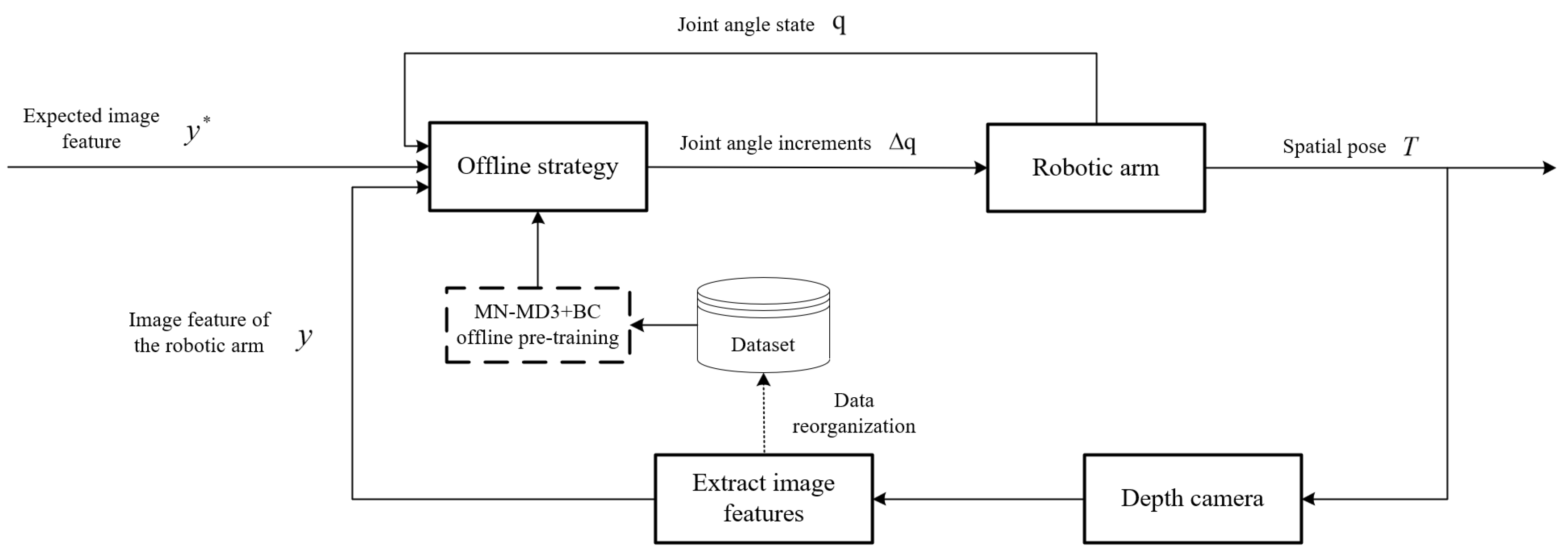
The MN-MD3+BC algorithm is an enhanced approach developed from the TD3 framework, specifically designed to address policy optimization challenges in uncalibrated robotic arm visual servoing tasks. The algorithm’s core innovation lies in its establishment of a coordinated learning system featuring “one actor network plus three critic networks” (as illustrated in Figure 2). This architecture employs three independent critic networks to evaluate policies from multiple perspectives, utilizing mean value computation for target Q-value estimation, which effectively mitigates potential estimation biases inherent in single-critic approaches. The algorithm implements a dual-objective optimization mechanism that dynamically weights behavior cloning loss against Q-value maximization objectives. This design ensures policy constraints remain within dataset-supported boundaries while preserving exploration capabilities in high-performance regions. In practical control processes, this balance manifests as the decision network’s dual capability: it reliably tracks effective actions from demonstration data while autonomously optimizing more precise motion trajectories.
In the robotic arm visual servoing control process, the system first extracts image features from camera-captured images. These extracted image features, combined with desired image features and current joint angles, form the state information that is fed into the policy network. The policy network then computes the joint angle variations based on the trained offline policy. These computed joint angle variations are subsequently executed by the robotic arm to perform the required movement. Following the arm’s motion, the system captures new image features again and repeats the aforementioned steps. This cyclic process continues iteratively until the visual servoing control task is successfully completed.
Figure 3.
Structure of the robotic arm visual servoing system based on MN-MD3+BC.
3.2. Network Structure Design
The network architecture of the Twin Delayed Deep Deterministic Policy Gradient (TD3) algorithm [30] consists of one policy network (Actor), two independent value networks (Critic), and their corresponding target networks. The policy network takes the current environmental state as input and outputs optimal continuous actions for environmental interaction. The Critic networks receive both state and action as inputs to independently estimate the Q-value of actions.
In conventional Actor-Critic frameworks, the Actor and Critic networks typically employ relatively consistent architectures, where the Critic network serves as an approximation of the state-action value function to evaluate actions generated by the Actor policy network. However, to address the overestimation bias inherent in traditional methods, TD3 adopts the Double Q-learning approach by utilizing two separate Critic networks to independently estimate Q-values and using their minimum for target updates.Although this design effectively mitigates overestimation bias, it may result in persistently low value estimation of actions output by the Actor network, thereby affecting the algorithm’s convergence speed and the conservativeness of the policy.
To address this limitation, we extend the TD3 framework by introducing M Critic networks with corresponding target networks. Instead of taking the minimum Q-value, we compute the mean across all Critic networks:
where M denotes the number of Critic networks, r denotes the reward value corresponding to the current action, denotes the discount factor, and denotes next state after taking the action.
Furthermore, for target policy regularization, noise is incorporated into the target policy:
where represents target policy regularization noise.
The Critic network parameters are updated by minimizing the following loss function:
where denotes a mini-batch of size N sampled from the experience replay buffer.
Although the TD3 algorithm has demonstrated excellent performance in online reinforcement learning, its core design relies on continuous interaction with the environment, which makes it unsuitable for direct application in offline reinforcement learning. In offline scenarios, the TD3 algorithm requires generating new actions during policy updates. However, these generated actions may deviate from the distribution of the offline dataset, leading to the distributional shift problem. Specifically, this shift can cause the value function to erroneously overestimate the policy’s performance, resulting in performance degradation or even policy collapse. To address the distributional shift issue in offline reinforcement learning, we have introduced Behavioral Cloning (BC) into the policy update process. The BC loss constrains the learned policy to remain close to the behavioral policy that generated the dataset:
The combined policy loss becomes a multi-objective optimization problem:
where controls the trade-off between Q-value maximization and behavior cloning.
The target networks are updated via soft updates:
where is the learning rate for target network updates.
3.3. State Space Definition
The state space of a robotic arm refers to the observed state information during its operation, encompassing both environmental states and the robotic arm’s own states. In the context of robotic arm control problems, the state space may include the robotic arm’s joint angles, the position of the end-effector, the position of the target point, and so forth. These elements serve as input variables that enable the robotic arm to acquire state information, based on which, along with the current policy, it selects appropriate actions to execute and subsequently obtains corresponding reward values.
For the calibration-free visual servoing task investigated in this study, environmental state perception primarily relies on visual sensor information. Specifically, the system employs a depth camera as the visual sensor, with acquired image features including the pixel’s horizontal coordinate u, the pixel’s vertical coordinate v, and the pixel’s depth value . These features collectively constitute the state space representation of the system. The robotic arm’s own state refers to the changing state of its structure, specifically the angle values of each joint. Due to the issue of degrees of freedom in robotic arms, a high degree of freedom robotic arm can have multiple inverse solutions for the same end-effector position. Therefore, the current joint angle values are necessary to seek the optimal policy that enables reaching the next position with minimal movement.
Since this paper focuses on the problem of tracking the target position of the robotic arm’s end-effector, the issue of the end-effector’s orientation is temporarily disregarded. The tracking of the robotic arm’s target position is a stochastic and continuous process, and the sole introduction of the current target position is not applicable to all tracking tasks. Consequently, this paper introduces the expected image feature of the target at the next moment into the state space. This feature value can be calculated through pre-set parameters or an independent target prediction algorithm, satisfying the requirements of positioning and tracking tasks. The state space is defined as:
where:
denotes the current image features with pixel coordinates and depth from the depth camera;
represents the expected target image features;
is the joint angle vector with n degrees of freedom.
3.4. Action Space Definition
To accomplish the robotic arm target tracking task, it is necessary to ensure that the end-effector of the robotic arm follows the movement of the target. The required state information, including environmental data and the joint angles of the robotic arm, has already been acquired. The action space should aim to minimize the distance between the end-effector position and the target position by providing the required joint angle changes for the next time step. These changes are then accumulated to the current joint angles, enabling the robotic arm to continuously adjust its angles and, consequently, the position of the end-effector. The action space defines the joint angle increments for trajectory tracking:
where each is bounded by the mechanical constraints .
3.5. Reward Function Design
The key to robotic arm target tracking lies in the acquisition of reward values, which represent the objective of the task and drive the learning strategy of the robotic arm. Without proper rewards, the arm would engage in endless, aimless movements. Therefore, designing an appropriate reward function is one of the critical elements in solving reinforcement learning problems.
In this section, with the task background of uncalibrated visual target tracking by a robotic arm, the reward function design must be based on the relative distance between the end-effector features and target features in the visual sensor’s frame, while also considering the magnitude of actions. Consequently, the proposed reward function consists of two components: distance reward and action reward, as expressed in the following equation:
with feature distance computed as:
where:
are weighting coefficients prioritizing tracking precision;
is the joint angle change vector.
3.6. Algorithm Training Process
In order to more clearly understand the implementation process, we propose the following pseudo code (Algorithm 1) for the training process of the MN-MD3+BC algorithm.
| Algorithm 1 MN-MD3+BC Training Procedure |
|
4. Experiments
To evaluate the performance of the MN-MD3+BC uncalibrated robotic arm visual adaptive control algorithm, this study conducted comprehensive testing and verification on both the Matlab simulation platform and the WPR1 experimental platform. The evaluation process focused on analyzing the algorithm’s accuracy in executing visual servoing tasks, thereby validating its adaptability across different platforms and task completion effectiveness.
4.1. Dataset Construction for Offline Pretraining
To enable effective pretraining of the MN-MD3+BC offline reinforcement learning algorithm proposed in Section 3, a tailored pretraining dataset must be constructed. The quality of this dataset critically influences the convergence of algorithm training and the performance of the learned policy, which subsequently impacts the effectiveness of the uncalibrated visual servoing control task. This section details a data-splicing-based dataset construction methodology aligned with visual servoing objectives.
4.1.1. Data Collection Phase
A robotic arm visual servoing system serves as the data source. The joint angles of the robotic arm are randomly initialized within their permissible limits. The arm executes random motions with varying joint velocity rates, where the action magnitude is constrained to the range . Joint angle limits are enforced throughout the motion. During motion execution, joint angle states and corresponding end-effector image features are recorded at each timestep. Data collection terminates if the end-effector image features are lost or when the maximum timestep threshold (2,000 steps) is reached. Repeat the data collection phase until 16 episodes are attained.
After discarding episodes prematurely terminated due to feature loss, approximately 30,000 valid data entries are collected.
4.1.2. Data Reorganization Phase
The raw dataset requires restructuring to align with reinforcement learning frameworks, where each experience replay buffer entry contains (state, action, reward, next-state) components:
- a)
- State Representation:where denotes current image features, is derived by offsetting subsequent features from the raw dataset, and represents joint angles.
- b)
- Action Derivation:
- c)
-
Reward Calculation:The reward function is set as Equation (14).
As illustrated in Figure 4, this reorganization generates complete training instances by associating . Cyclic processing of the raw dataset produces the final pretraining dataset for the experience replay buffer, ensuring compatibility with the state/action spaces and reward function defined in previous section.
4.2. Matlab Simulation Platform Experiments
The simulation environment is built using Robotics Toolbox and Machine Vision Toolbox in MATLAB. We compare MN-MD3+BC with TD3+BC and Model-Free Adaptive Control (MFAC).
In the simulated PUMA560 visual servoing system, the visual measurements consist of the pixel coordinates of target points and their depth values . Considering that the first three joints of the PUMA560 control the end-effector’s positional degrees of freedom (DOFs) in Cartesian space while the last three joints govern spatial attitude, this study focuses solely on end-effector position tracking. By neglecting spatial attitude control, the problem is simplified to a 3-DOF robotic arm control task. The control inputs are defined as the first three joint angles (in radians):
To evaluate the performance of different algorithms across various trajectories, a comparative experiment is conducted between the final policy networks obtained from the MN-MD3+BC and TD3+BC algorithms (trained for steps) and the MFAC algorithm. The hyperparameter settings for the experiments are listed in the Table 3.
Experiment 1: Spiral Trajectory Tracking
The target spiral trajectory is defined as:
The trajectory tracking performance of the three algorithms is illustrated in Figure 5.
The experimental results from Figure 5 clearly demonstrate that compared with the MFAC algorithm, the MN-MD3+BC algorithm and the TD3+BC algorithm perform better in terms of error convergence, and can converge the error to zero more quickly. This indicates that the robotic arm visual servo control method combined with reinforcement learning outperforms the traditional model-free control method based on the Jacobian matrix in terms of response speed, and the convergence speed of the MN-MD3+BC algorithm is slightly faster than that of the TD3+BC algorithm. During the subsequent tracking process, all three algorithms exhibit error fluctuations to varying degrees. Among them, the error fluctuations of the TD3+BC algorithm and the MFAC algorithm are relatively obvious, with large fluctuations occurring in the middle and late stages of the tracking task, respectively. In contrast, the error curve of the MN-MD3+BC algorithm is relatively stable, with a smaller fluctuation range, demonstrating better tracking stability and precision.
Experiment 2: Circular Trajectory Tracking
The target circular trajectory is defined as:
The trajectory tracking performance of the three algorithms is illustrated in Figure 6.
As shown in the Figure 6, during the process of approaching the target trajectory, the MN-MD3+BC algorithm and the TD3+BC algorithm exhibit almost the same trajectory, with only a slight separation of the trajectories occurring at the moment of approaching the target trajectory. In contrast, the MFAC algorithm approaches the target trajectory gradually along a more tortuous path. During the tracking period, there is a noticeable gap between the motion trajectories of the TD3+BC algorithm and the MFAC algorithm and the target trajectory, indicating a certain deviation. However, the tracking trajectory of the MN-MD3+BC algorithm basically coincides with the target trajectory, demonstrating higher tracking accuracy. The MN-MD3+BC algorithm still has a faster convergence speed, being able to converge the error to zero more quickly, and the error fluctuation range during the tracking process is also relatively small, indicating that the MN-MD3+BC algorithm has higher stability.
To further compare the performance of the three algorithms, we calculated both the mean and variance of image feature tracking errors for Experiment 1 and Experiment 2. The mean feature error reflects the algorithm’s accuracy, while the variance of feature error indicates the fluctuation degree of errors. The detailed data are presented in Table 4.
As evidenced by the Table 4, in Experiment 1, the MN-MD3+BC algorithm achieved the lowest mean feature error along with significantly smaller error variance compared to the other two algorithms, demonstrating its superior tracking performance. This advantage remained consistent in Experiment 2, where MN-MD3+BC maintained both lower mean feature error and reduced error variance, confirming its overall outstanding performance across different test conditions.
In conclusion, compared with the traditional model-free method based on the Jacobian matrix, the robotic arm visual servo control method combined with reinforcement learning has a faster response and smaller errors. In addition, the MN-MD3+BC algorithm proposed in this paper shows excellent tracking performance in the experiments, demonstrating further advantages over the TD3+BC algorithm.
4.3. WPR1 Experimental Platform Validation
To further verify the effectiveness of the proposed algorithm, based on the analysis of the hardware and software environmental parameters of the WPR1 robotic arm experimental platform presented in Section 2, a depth camera-based WPR1 robotic arm visual servoing system was constructed on this experimental platform. The proposed MN-MD3+BC algorithm was compared with the Model-Free Adaptive Control algorithm (MFAC algorithm) and the TD3+BC algorithm in real visual servoing tasks. In this section, the visual servoing measurements include the pixel coordinates and depth values of the target points in the image. Different from Section 4.2, the control outputs in this section are the radian values of the six joint angles.
4.3.1. Static Target Positioning Experiment
The initial image features of the robotic arm are denoted as (440, 254, 870). The target object is placed at 10 different locations, and positioning experiments are conducted for each location. The positioning results of the two algorithms are derived based on the motion of the robotic arm. Due to inherent errors in the visual servoing system of the robotic arm, the positioning phase may be continuously affected by disturbances, causing slight movements without reaching a complete static. As a result, it is challenging to obtain a definitive final positioning result.
To compare the positioning errors of the algorithms, the observed feature values at the 50th timestep during the motion are selected as the positioning results for the end-effector image features. The experimental results are summarized in Table 5.
As shown in Table 5, in all 10 experimental trials, none of the three algorithms experienced image feature loss, and the WPR1 robotic arm successfully positioned itself near the target point in each case. The three algorithms demonstrated similar average feature errors, with no significant differences observed in positioning accuracy.
To further analyze the positioning performance of these algorithms, we selected one set of data from these 10 experiments for detailed examination. This section focuses specifically on the data from Experiment 2 to conduct a more in-depth comparison and evaluation of their positioning effectiveness. The comparative results are illustrated in the Figure 7.
As shown in the Figure 7, although all three algorithms can position near the target point, compared with the other two algorithms, the MN-MD3+BC algorithm can more directly position near the target point, demonstrating superior convergence performance by achieving faster convergence to steady state while maintaining errors at a smaller level. In contrast, the MFAC algorithm shows significantly slower convergence speed than MN-MD3+BC, and its positioning error remains consistently larger than that of MN-MD3+BC throughout the entire process. While the TD3+BC algorithm’s convergence speed is only slightly slower than MN-MD3+BC, its error fluctuations are noticeably greater than those of the MN-MD3+BC algorithm.
In summary, for visual servoing tasks involving static target positioning, the MN-MD3+BC algorithm proposed in this paper demonstrates significantly better overall performance compared to both the traditional Jacobian matrix-based Model-Free Adaptive Control algorithm and the TD3+BC algorithm, exhibiting faster response speed and smaller positioning errors.
4.3.2. Dynamic Target Tracking Experiments
This section conducts target tracking experiments on the object using the previously proposed MFAC algorithm, TD3+BC algorithm, and MN-MD3+BC algorithm respectively, to further compare the performance of the three algorithms.
To ensure the fairness of the comparative experiments, it is necessary to guarantee that the dynamic targets tracked by the three algorithms follow identical motion processes. Therefore, the target motion in this section is pre-recorded by having the experimenter manually move a red ball along a predetermined trajectory. All three algorithms receive the target image features at the same frequency and control the WPR1 robotic arm accordingly. Since the target ball’s velocity is manually controlled by the experimenter, precise speed regulation is impossible, but an approximate velocity of 0.05 m/s is maintained as consistently as possible.
Multiple types of target motion trajectories were collected in this section, from which two representative trajectories were selected for algorithm analysis. By comparing the tracking trajectories and tracking errors of the three algorithms, their relative strengths and weaknesses can be evaluated. The comparative results are illustrated in Figure 8 and Figure 9.
The evaluation of trajectory tracking performance revealed distinct differences among the three control algorithms (as shown in the Figure 8). Experimental results indicate that the MFAC algorithm exhibited noticeable trajectory jitter when approaching the target path, while both the TD3+BC and MN-MD3+BC algorithms demonstrated smoother tracking trajectories. It is worth noting that in the later stages of the tracking task, all three algorithms achieved good alignment with the target trajectory, confirming their fundamental capability to complete the tracking task.
Through in-depth analysis of error characteristics, it was found that the MFAC algorithm showed significant tracking errors during the initial tracking phase, revealing deficiencies in its control computation process. To further compare the control performance of different algorithms, this study conducted a magnified analysis of tracking errors during the system’s stable phase. The results demonstrate that compared to the MN-MD3+BC algorithm, the TD3+BC algorithm exhibited more pronounced error fluctuations, with this difference being particularly evident in the vertical (v) direction error metrics.
Overall, the MN-MD3+BC algorithm demonstrated optimal robustness with the smallest error fluctuation amplitude, indicating that it possesses more stable control performance and higher tracking accuracy in trajectory tracking tasks.
The experimental results show that the three control algorithms exhibit significant differences in complex trajectory tracking tasks (as shown in the Figure 9). The test trajectory contains various motion characteristics including curves, straight lines and sharp turns, providing comprehensive verification for algorithm performance evaluation. Although the three algorithms show similar temporal characteristics when approaching the target trajectory, there are obvious differences in trajectory accuracy and stability.
Specifically, the MN-MD3+BC algorithm demonstrates the best comprehensive performance, with its generated tracking trajectories not only showing optimal smoothness but also maintaining high consistency with the reference trajectory. In comparison, the MFAC algorithm exhibits obvious trajectory deviation during turning segments, indicating inherent limitations of traditional Jacobian matrix-based model-free methods in complex motion tracking. While the TD3+BC algorithm shows improvement over MFAC, it still displays relatively large trajectory fluctuations, especially at sharp “V”-shaped turns.
The error comparison plots reveal deeper performance differences. The MFAC algorithm performs worst, showing the largest tracking errors in the initial phase that are significantly greater than the other two algorithms. Although the converged tracking error of TD3+BC is only slightly worse than MN-MD3+BC, the enlarged plots clearly show that TD3+BC has greater fluctuations.
In terms of control components, all three algorithms maintain similarly low steady-state errors in the u and depth directions. However, in the v component, the MFAC algorithm shows significant fluctuations in the initial phase, while the TD3+BC algorithm still exhibits additional fluctuations compared to MN-MD3+BC. These differences are particularly evident in trajectory segments containing sharp turns. These experimental results further confirm that the MN-MD3+BC algorithm has advantages in both control stability and precision.
The comprehensive experimental results demonstrate that in complex visual servoing tasks, the MN-MD3+BC algorithm not only significantly outperforms traditional model-free methods but also shows performance improvements over the TD3+BC algorithm, verifying its advantages in control accuracy, stability and robustness.
4.3.3. Comprehensive Performance Comparison
To ensure the reliability and generalization of the experimental conclusions, this study conducted systematic evaluation of algorithm performance through multiple repeated experiments (including ten static target positioning experiments and fifteen dynamic target tracking experiments). Table 6 and Table 7 respectively present the key performance metrics of the three algorithms in point-to-point positioning experiments and trajectory tracking experiments: mean feature error, average convergence steps, and feature error variance. Here, the mean feature error quantifies positioning accuracy (smaller values indicate higher precision), average convergence steps reflect dynamic convergence speed (fewer steps indicate faster convergence), and feature error variance characterizes steady-state stability (smaller variance indicates better stability).
The comprehensive performance comparison demonstrates that the MN-MD3+BC algorithm significantly outperforms the MFAC algorithm in terms of positioning accuracy, convergence speed, and stability. The MN-MD3+BC algorithm achieves lower mean absolute error and requires fewer average convergence steps than the MFAC algorithm, indicating faster convergence speed. Furthermore, in dynamic trajectory tracking experiments, the MN-MD3+BC algorithm exhibits lower feature error variance compared to the other two algorithms, further verifying its superior stability.
These quantitative results fully validate the comprehensive advantages of the MN-MD3+BC algorithm in visual servoing control tasks. Particularly in application scenarios requiring high-precision positioning and fast response, the algorithm’s excellent performance demonstrates significant practical value. The consistency of experimental data indicates that the proposed improved algorithm not only possesses theoretical innovation but also shows reliable performance enhancement in practical applications.
5. Conclusions
Different from the existing methods for designing robotic arm vision controllers based on online reinforcement learning, this paper proposed a deterministic policy gradient offline reinforcement learning algorithm based on multi-evaluation network averaging (MN-MD3+BC algorithm) from the perspective of real-world applications, in response to the problems of training inefficiency and underutilized data faced by online reinforcement learning in a high-dimensional state space. The algorithm made targeted improvements on the basis of the TD3+BC offline reinforcement learning algorithm, especially achieved breakthroughs in performance optimization in the uncalibrated visual servoing task. The MN-MD3+BC algorithm improves the accuracy of the value evaluation by means of multi-evaluating network averaging, and at the same time enhances the robustness of the strategy, effectively avoiding the traditional reinforcement learning algorithm in the process of strategy convergence common overestimation bias problem of traditional reinforcement learning algorithms in the process of strategy convergence. Compared with online reinforcement learning, the algorithm substantially reduces the dependence on real-time environment interaction during the training process by pre-training the policy network offline, which enhances the practicality in real robotic arm control tasks.
In order to verify the performance of the proposed algorithm, comparative experiments were conducted in Matlab custom simulation environment and the actual WPR1 robotic arm experimental platform. The experimental results show that the MN-MD3+BC algorithm exhibits significant advantages in terms of tracking accuracy, error convergence speed and system stability compared with the traditional model-free control method. Especially when dealing with visual servo tasks such as complex trajectories and sharp turns, the MN-MD3+BC algorithm is able to converge to the target trajectory more quickly and with smaller error fluctuations, showing better robustness and control performance.
In summary, the MN-MD3+BC algorithm proposed in this paper not only overcomes the limitations of traditional calibrated methods, but also effectively addresses the challenges faced by online reinforcement learning in real-time control tasks, providing an efficient and practical offline reinforcement learning solution. Verified by simulation and physical experiments, the research results in this paper provide new ideas and references for future research in the field of visual servo control of robotic arms, and have important theoretical significance and application prospects. However, the method still has some limitations. First, although offline reinforcement learning can reduce the dependence on environment interaction, its performance is highly dependent on the diversity and coverage of training data, and it may suffer from insufficient generalization ability when dealing with unseen working conditions. In addition, as the behavioral cloning strategy may lead to over-reliance on historical data for policy updates, it may affect the exploration ability of the policy in unknown environments. Therefore, future research will focus on how to further improve the algorithm’s generalization ability as well as the exploration-exploitation balance to achieve a more efficient and robust visual servo control system.
Author Contributions
Conceptualization, J.W.; Data curation, C.Z.; Formal analysis, J.W.; Funding acquisition, X.Z.; Investigation, C.Z.; Methodology, X.Z.; Project administration, X.Z.; Resources, X.Z.; Software, C.Z.; Supervision, X.Z.; Validation, J.W.; Visualization, J.W.; Writing—original draft, J.W.; Writing—review and editing, X.Z. All authors have read and agreed to the published version of the manuscript.
Funding
This work was supported by the project from the National Natural Science Foundation of China under Grant 62073210.
Institutional Review Board Statement
Not applicable.
Informed Consent Statement
Not applicable.
Data Availability Statement
The original contributions presented in the study are included in the article, further inquiries can be directed to the corresponding author. Dataset available on request from the authors. The raw data supporting the conclusions of this article will be made available by the authors on request.
Conflicts of Interest
The authors declare that the research was conducted in the absence of any commercial or financial relationships that could be construed as a potential conflict of interest.
References
- Dobra, Z.; Dhir, K. S. Technology Jump in the Industry: Human-Robot Cooperation in Production. Ind. Robot 2020, 47 (5), 757–775. [CrossRef]
- Beisekenov, N.; Hasegawa, H. Advanced Preprocessing Technique for Tomato Imagery in Gravimetric Analysis Applied to Robotic Harvesting. Appl. Sci. 2024, 14 (2), 511. [CrossRef]
- Cristina, G.; Goldie, N. Human-Robot Interactions with an Autonomous Health Screening Robot in Long-Term Care Settings. Adv. Robot. 2023, 37 (24), 1576–1590.
- Ivan, V.; Ildar, F.; Brice, D.; et al. A Suite of Robotic Solutions for Nuclear Waste Decommissioning. Robotics 2021, 10 (4), 112.
- Michael, P.; Aaron, P.; Harsimran, S.; et al. Exploring Planet Geology through Force-Feedback Telemanipulation from Orbit. Sci. Robot. 2022.
- Li, M. Research on Key Technologies of Uncalibrated Visual Servoing for Robots. Ph.D. Thesis, Harbin Institute of Technology, 2010.
- Li, B.; Fang, Y.; Zhang, X. Visual Servo Regulation of Wheeled Mobile Robots with an Uncalibrated Onboard Camera. IEEE/ASME Trans. Mechatron. 2015, 21 (5), 2330–2342. [CrossRef]
- Cai, C.; Somani, N.; Knoll, A. Orthogonal Image Features for Visual Servoing of a 6-DOF Manipulator with Uncalibrated Stereo Cameras. IEEE Trans. Robot. 2016, 32 (2), 452–461.
- Qiu, Y.; Li, B.; Shi, W.; et al. Visual Servo Tracking of Wheeled Mobile Robots with Unknown Extrinsic Parameters. IEEE Trans. Ind. Electron. 2019, 66 (11), 8600–8609.
- Qiu, Z.; Hu, S.; Liang, X. Disturbance Observer Based Adaptive Model Predictive Control for Uncalibrated Visual Servoing in Constrained Environments. ISA Trans. 2020, 106, 40–50. [CrossRef]
- Li, X. A.; Sun, K.; Guo, C.; et al. Hybrid Adaptive Disturbance Rejection Control for Inflatable Robotic Arms. ISA Trans. 2022, 126, 617–628.
- Yilmaz, C. T.; Watson, C.; Morimoto, T. K.; et al. Adaptive Model-Free Disturbance Rejection for Continuum Robots. Automatica 2025, 171, 111949. [CrossRef]
- Pei, X.; Fang, X.; Wen, L.; et al. Data-Driven Model-Free Adaptive Containment Control for Uncertain Rehabilitation Exoskeleton Robots with Input Constraints. Actuators 2024, 13, 382.
- Mahmoud, F.; Maarouf, S.; Roberto, E. L.; et al. New Fixed-Time Observer-Based Model-Free Fixed-Time Sliding Mode of Joint Angle Commanded NAO Humanoid Robot. IEEE Trans. Control Syst. Technol. 2024, 3469051.
- Gu, S.; Holly, E.; Lillicrap, T.; et al. Deep Reinforcement Learning for Robotic Manipulation with Asynchronous Off-Policy Updates. In Proceedings of the 2017 IEEE International Conference on Robotics and Automation (ICRA), Singapore, May 29–June 3, 2017; pp 3389–3396. [CrossRef]
- Liu, Q.; Liu, Z.; Xiong, B.; et al. Deep Reinforcement Learning-Based Safe Interaction for Industrial Human-Robot Collaboration Using Intrinsic Reward Function. Adv. Eng. Inf. 2021, 49, 101360. [CrossRef]
- Lin, G.; Zhu, L.; Li, J.; et al. Collision-Free Path Planning for a Guava-Harvesting Robot Based on Recurrent Deep Reinforcement Learning. Comput. Electron. Agric. 2021, 188, 106350.
- Jiang, D.; Wang, H.; Lu, Y. Mastering the Complex Assembly Task with a Dual-Arm Robot Based on Deep Reinforcement Learning. IEEE Robot. Autom. Mag. 2023, 30 (1), 78–89.
- Qi, G.; Li, Y. Reinforcement Learning Control for Robot Arm Grasping Based on Improved DDPG. In Proceedings of the 2021 40th Chinese Control Conference (CCC), Shanghai, China, July 26–28, 2021; pp 4132–4137.
- Zhao, M.; Zuo, G.; Yu, S.; et al. Position-Aware Pushing and Grasping Synergy with Deep Reinforcement Learning in Clutter. CAAI Trans. Intell. Technol. 2023, 8 (2), 345–358.
- Sun, S.; Zhao, X.; Li, Q.; et al. Inverse Reinforcement Learning-Based Time-Dependent A* Planner for Human-Aware Robot Navigation with Local Vision. Adv. Robot. 2020, 34 (13), 888–901.
- Singh, B.; Kumar, R.; Singh, V. P. Reinforcement Learning in Robotic Applications: A Comprehensive Survey. Artif. Intell. Rev. 2022, 55 (2), 945–990. [CrossRef]
- Iriondo, A.; Lazkano, E.; Susperregi, L.; et al. Pick and Place Operations in Logistics Using a Mobile Manipulator Controlled with Deep Reinforcement Learning. Appl. Sci. 2019, 9 (2), 348.
- Minija, T.; Tamim, A.; Florentin, W. Learning to Reach by Reinforcement Learning Using a Receptive Field Based Function Approximation Approach with Continuous Actions. Biol. Cybern. 2009, 100 (3), 249–260.
- Zhang, F.; Leitner, J.; Milford, M.; et al. Towards Vision-Based Deep Reinforcement Learning for Robotic Motion Control. In Proceedings of the 2015 International Conference on Robotics and Automation, Seattle, WA, USA, May 26–30, 2015; pp 573–579.
- Wu, Y. H.; Yu, Z. C.; Li, C. Y.; et al. Reinforcement Learning in Dual-Arm Trajectory Planning for a Free-Floating Space Robot. Aerosp. Sci. Technol. 2020, 98, 105657. [CrossRef]
- Wong, C. C.; Chien, S. Y.; Feng, H. M.; et al. Motion Planning for Dual-Arm Robot Based on Soft Actor-Critic. IEEE Access 2021, 9, 26871–26885. [CrossRef]
- Yang, S. H.; Xie, X. B.; Bing, Z. K.; et al. Path Planning for Walnut Harvesting Manipulator Based on HER-TD3 Algorithm. Trans. Chin. Soc. Agric. Mach. 2023, 54 (6), 123–138.
- Fujimoto, S.; Gu, S. S. A Minimalist Approach to Offline Reinforcement Learning. Adv. Neural Inf. Process. Syst. 2021, 34, 20132–20145.
- Fujimoto, S.; van Hoof, H.; Meger, D. Addressing Function Approximation Error in Actor-Critic Methods. In Proceedings of the 35th International Conference on Machine Learning, Stockholm, Sweden, July 10–15, 2018; pp 1587–1596.
Figure 1.
WPR1 Experimental Platform.
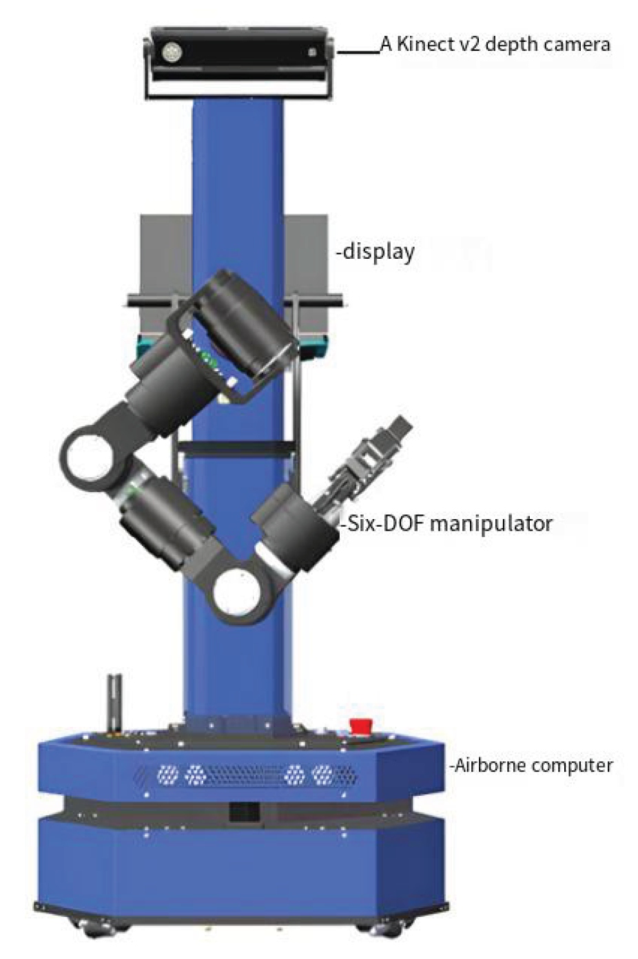
Figure 2.
Overall framework of the MN-MD3+BC algorithm.
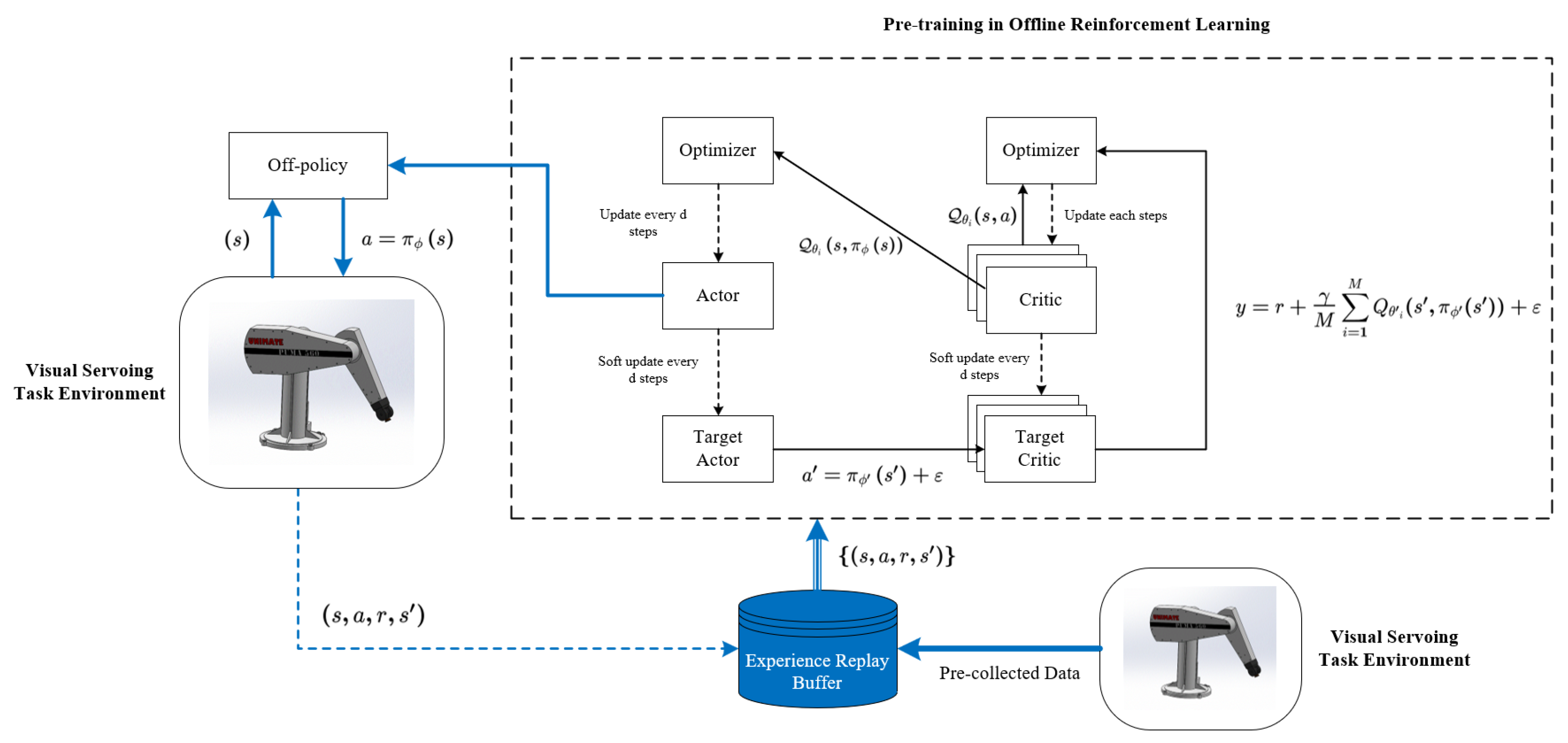
Figure 4.
The Process of Data Reorganization.
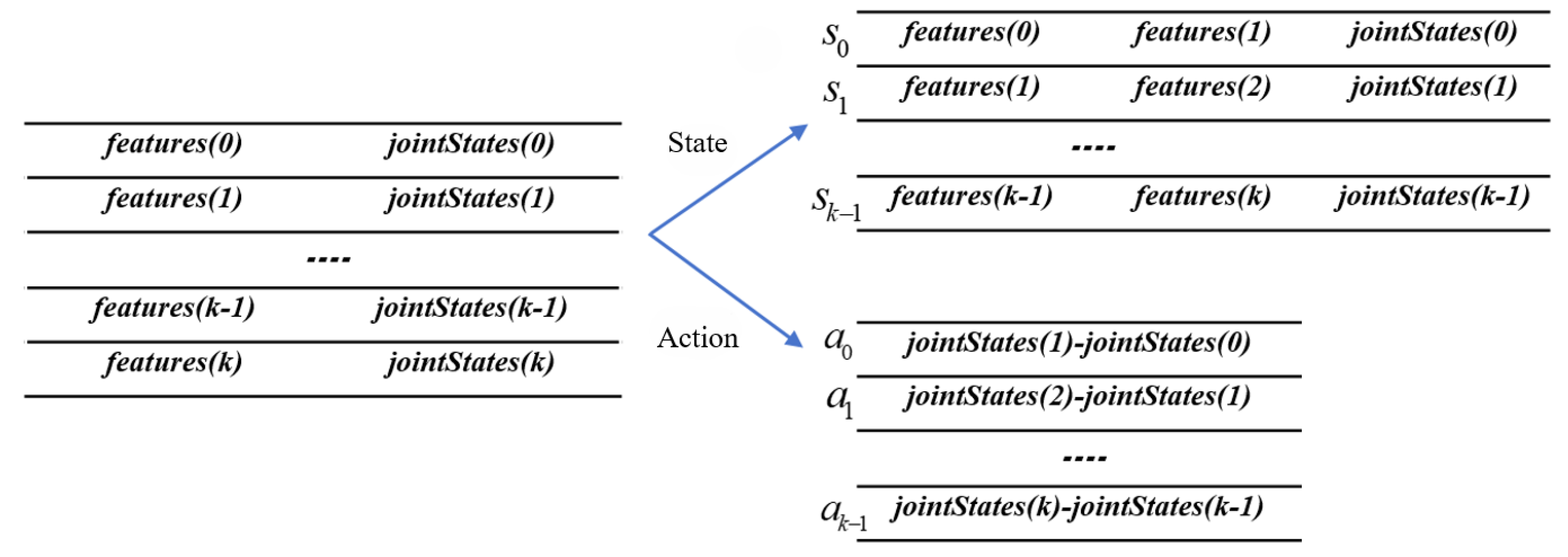
Figure 5.
Experimental results for spiral trajectory tracking.
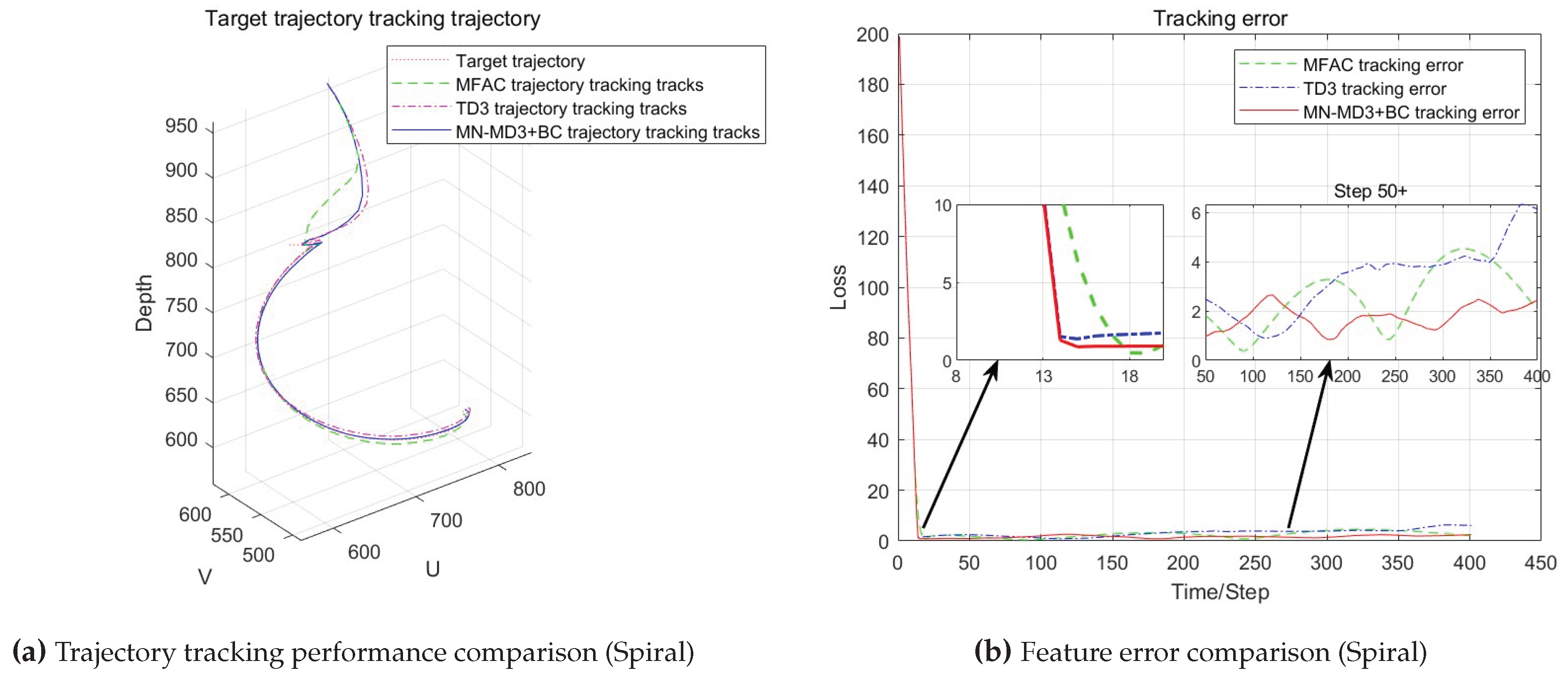
Figure 6.
Experimental results for circle trajectory tracking.
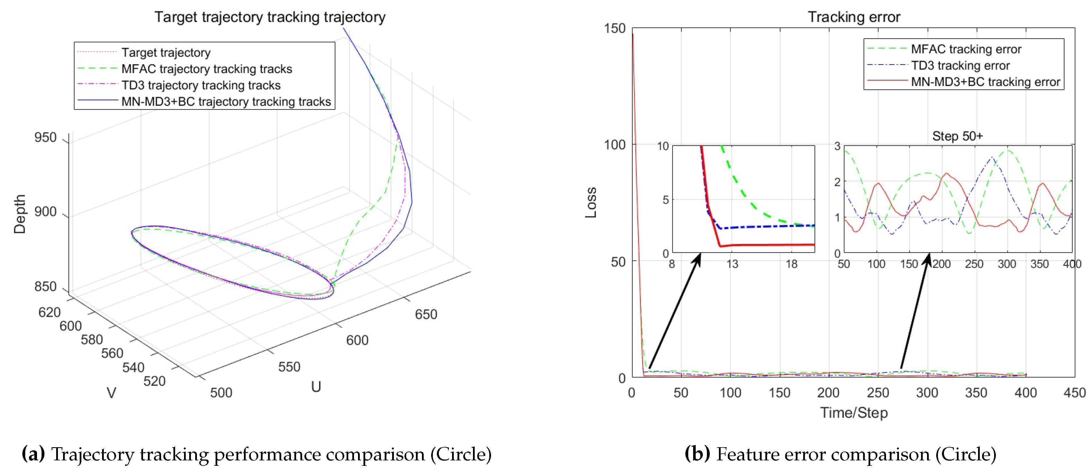
Figure 7.
Experimental results for Experiment 2.
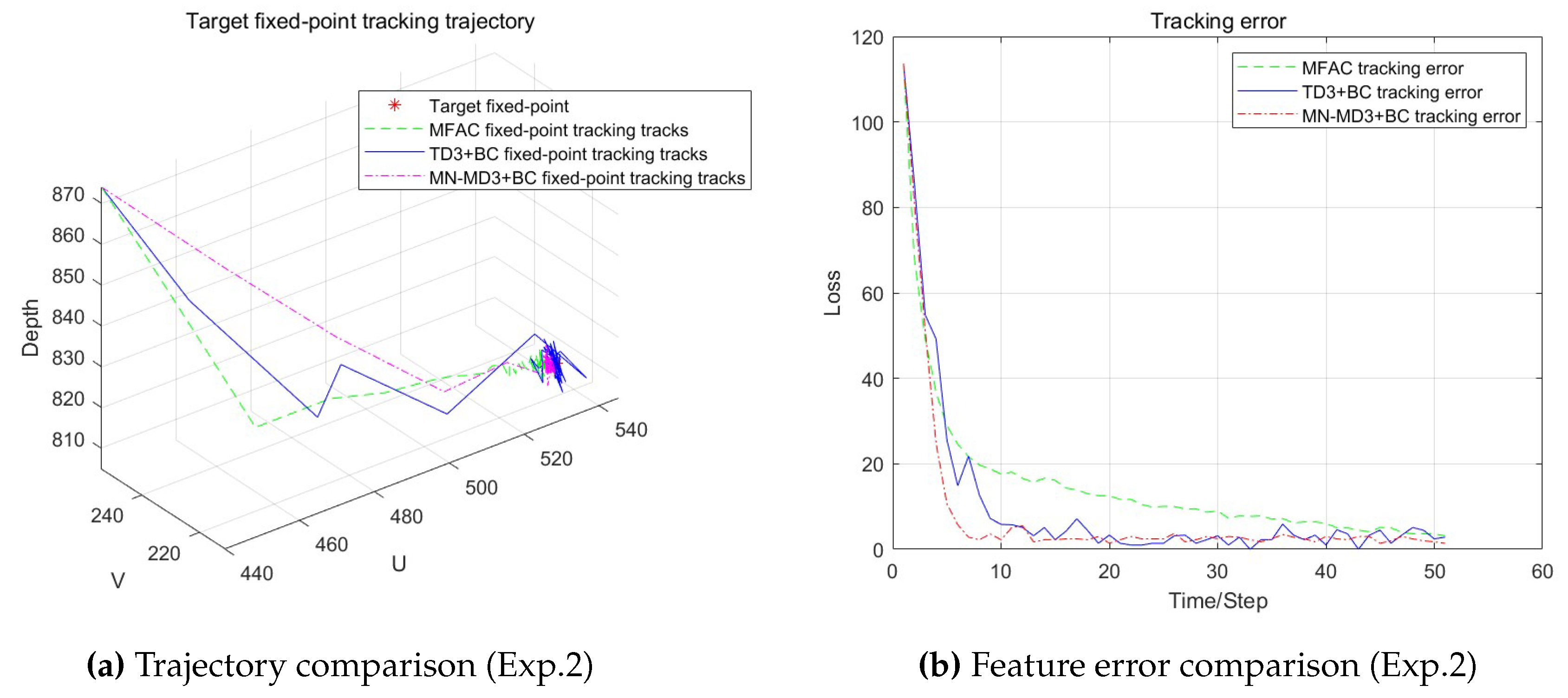
Figure 8.
Comparative trajectory tracking performance.
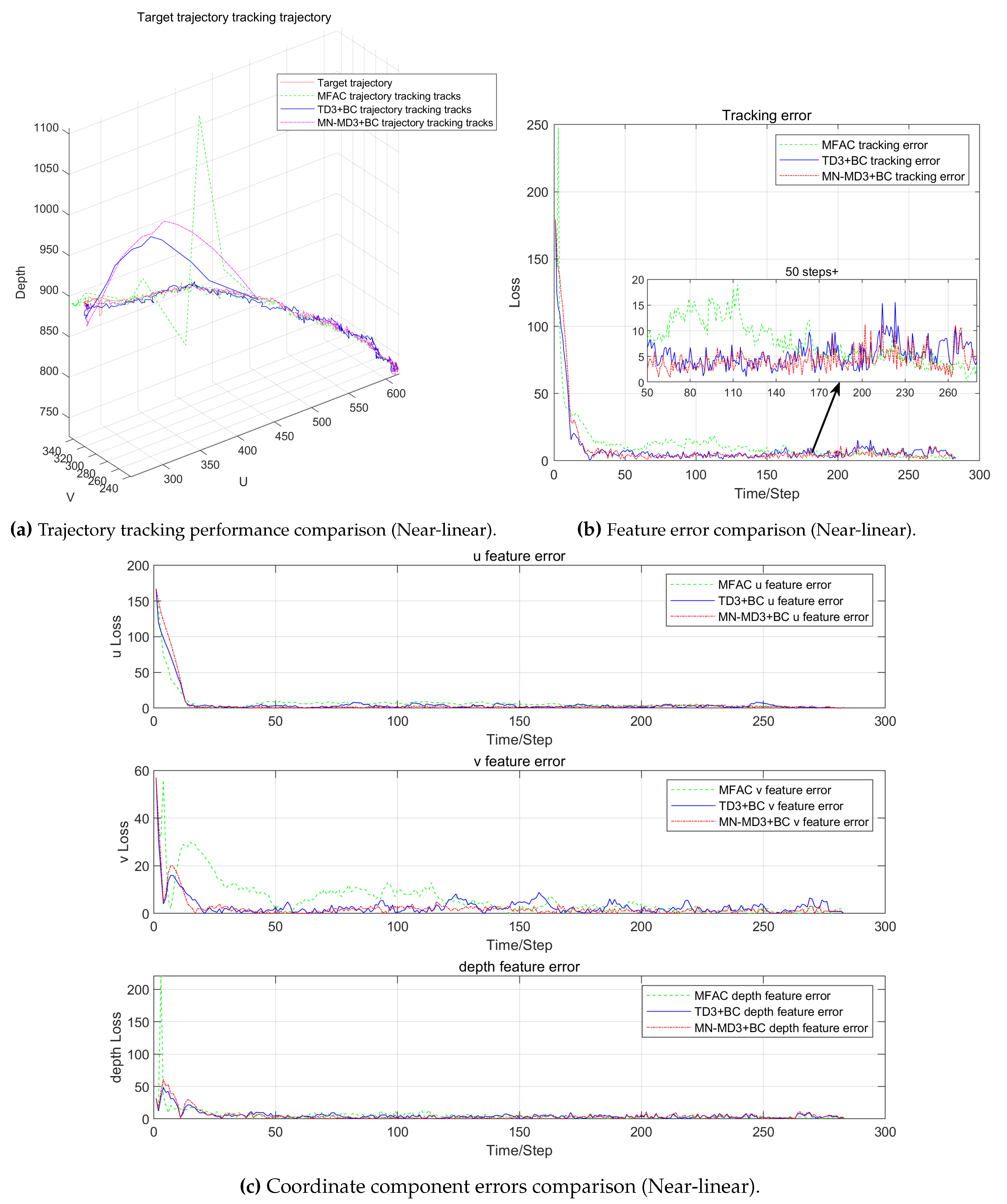
Figure 9.
Comparative trajectory tracking performance.
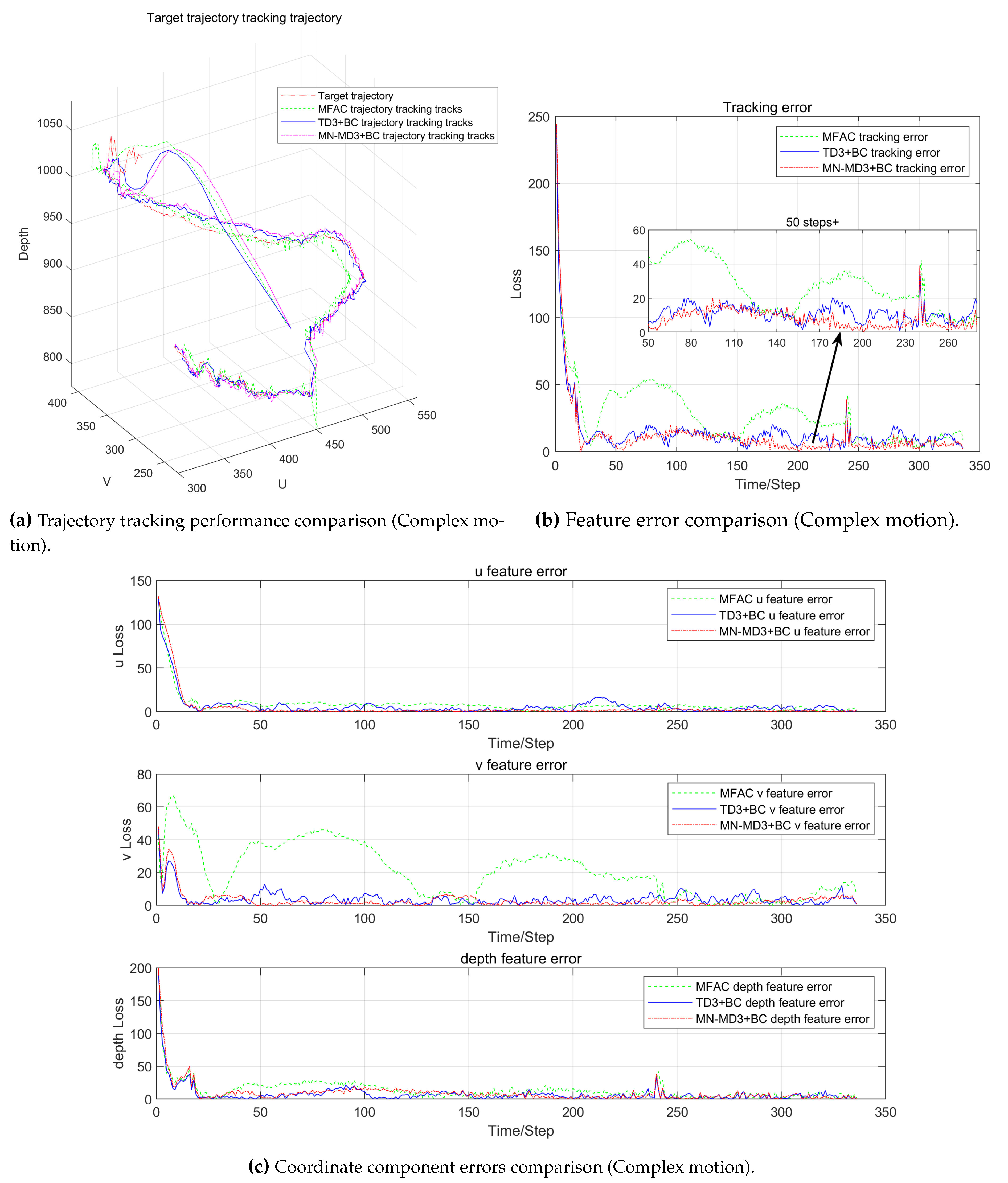

Table 1.
Joint Limits of the WPR1 Robotic Arm.
| Joint Number | Range of Motion |
| 1 | to |
| 2 | to |
| 3 | to |
| 4 | to |
| 5 | to |
| 6 | to |
Table 2.
D-H Parameters of the PUMA560 Model.
| Link | d | a | θ | α | Limits |
| 1 | 0 | 0 | to | ||
| 2 | 0 | 0 | to | ||
| 3 | to | ||||
| 4 | 0 | to | |||
| 5 | 0 | 0 | to | ||
| 6 | 0 | 0 | 0 | to |
Table 3.
Hyperparameter Configuration.
| Parameter | Reinforcement Learning | MFAC | |
| MN-MD3+BC | TD3+BC | ||
| Max timesteps | 1e5 | 1e5 | - |
| Batch size | 8 | 8 | - |
| Discount factor () | 0.99 | 0.99 | - |
| Target update rate () | 0.005 | 0.005 | - |
| Policy noise | 0.2 | 0.2 | - |
| Noise clip | 0.5 | 0.5 | - |
| Critic networks | 3 | 2 | - |
| - | - | 0.05 | |
| - | - | 1.096 | |
| - | - | 0.92 | |
| - | - | 1.56 | |
Table 4.
Error Analysis.
| Exp. No. | Algorithm | Mean Error | Variance |
| MFAC | 10.443 | 1.348 | |
| 1 | TD3+BC | 6.353 | 1.157 |
| MN-MD3+BC | 4.871 | 0.315 | |
| MFAC | 8.447 | 0.882 | |
| 2 | TD3+BC | 3.203 | 0.276 |
| MN-MD3+BC | 3.107 | 0.247 |
Table 5.
Positioning Results on WPR1 Platform (Feature Coordinates).
| Exp. No. | Target Feature | MFAC | TD3+BC | MN-MD3+BC |
|---|---|---|---|---|
| 1 | (410,235,840) | (410,236,839) | (410,235,838) | (410,235,837) |
| 2 | (530,213,818) | (530,215,820) | (529,215,819) | (529,214,818) |
| 3 | (450,250,850) | (451,250,852) | (450,249,851) | (450,248,851) |
| 4 | (510,220,890) | (511,222,887) | (510,220,888) | (510,218,890) |
| 5 | (500,200,900) | (500,204,902) | (501,201,900) | (502,198,899) |
| 6 | (515,232,795) | (515,230,795) | (515,230,796) | (515,230,797) |
| 7 | (520,180,780) | (520,182,778) | (520,180,776) | (518,179,780) |
| 8 | (480,270,820) | (479,269,823) | (479,271,824) | (480,272,823) |
| 9 | (390,300,800) | (390,300,802) | (390,300,800) | (391,299,799) |
| 10 | (460,300,790) | (460,299,789) | (459,299,789) | (457,298,790) |
| MAE | 2.625 | 2.597 | 2.566 | |
Note: Feature coordinates represent (u, v, depth) in pixel-space.
Table 6.
Comparative Analysis of Comprehensive Positioning Performance in Fixed-point Experiments.
| Metric | MFAC | TD3+BC | MN-MD3+BC |
|---|---|---|---|
| Mean Feature Error | 12.622 | 8.967 | 6.473 |
| Mean Convergence Steps (step) | 30.56 | 12.84 | 9.23 |
Table 7.
Comparative Analysis of Comprehensive Performance in Trajectory Tracking Experiments.
| Metric | MFAC | TD3+BC | MN-MD3+BC |
|---|---|---|---|
| Mean Feature Error | 29.425 | 10.175 | 9.475 |
| Mean Convergence Steps (step) | 27.32 | 21.92 | 20.18 |
| Feature Error Variance | 218.63 | 34.551 | 22.82 |
Disclaimer/Publisher’s Note: The statements, opinions and data contained in all publications are solely those of the individual author(s) and contributor(s) and not of MDPI and/or the editor(s). MDPI and/or the editor(s) disclaim responsibility for any injury to people or property resulting from any ideas, methods, instructions or products referred to in the content. |
© 2025 by the authors. Licensee MDPI, Basel, Switzerland. This article is an open access article distributed under the terms and conditions of the Creative Commons Attribution (CC BY) license (http://creativecommons.org/licenses/by/4.0/).
Copyright: This open access article is published under a Creative Commons CC BY 4.0 license, which permit the free download, distribution, and reuse, provided that the author and preprint are cited in any reuse.


