
Submitted:
21 August 2025
Posted:
22 August 2025
You are already at the latest version
Abstract
The (AlFeCoNi)C high-entropy alloy carbide films (HECFs) with tunable carbon contents were fabricated by magnetron sputtering to investigate the carbon-driven structural evolution and its coupling effects on mechanical and chemical properties. With increasing carbon incorporation (0-47.6 at.%), the HECFs formed a composite structure of amorphous phase and BCC nanocrystalline phase, as evidenced by XRD and TEM. Atom probe tomography (APT) reveals Al segregation in the film. Remarkably, the wear rate decreases exponentially from 5.3×10⁻⁵ to 1.3×10⁻5 mm³/N·m, attributed to the amorphous carbon phase acting as solid lubricant. Simultaneously, the corrosion current density reduces by two orders of magnitude (7.2×10⁻⁸ A/cm² in 3.5% NaCl), benefiting from the amorphous network inhibiting ion diffusion pathways. This work establishes a carbon-content-property correlation paradigm for designing multifunctional HEA films in extreme environments.
Keywords:
high-entropy alloy films
; carbon doping
; structural transition
; tribological properties
; corrosion resistance
1. Introduction
High-entropy alloy films (HEAFs) have emerged as promising candidates[1,2,3] for extreme-environment applications, such as aerospace components, marine engineering systems, and nuclear reactors, where materials are subjected to simultaneous mechanical wear and corrosive degradation. While conventional HEAFAs exhibit exceptional strength and thermal stability, their performance in tribological and chemically aggressive environments remains constrained by intrinsic limitations: single-phase structures often lack adaptive lubrication mechanisms, while grain boundaries and defects in crystalline phases provide pathways for corrosive ion penetration. Addressing this dual challenge requires innovative strategies to decouple structural design from property trade-offs.
AlFeCoNi-based high-entropy thin films[4,5] exhibit outstanding comprehensive mechanical properties, combining high hardness with high toughness. However, they still face significant challenges in corrosion resistance and wear resistance. Currently, researchers primarily enhance their performance through alloying. Goodelman et al.[6] investigated the influence of Ti and Al atomic content on the properties of thin films in the AlCoCrFeNiTi system. They found that Al and Ti, as "large atomic radius elements" (>140 pm), competitively drive phase formation. Ti content exceeding 7 at.% induces amorphization, while below this threshold, Al promotes an ordered BCC structure (with high Al content leading to enhanced crystallinity). Wu et al.[7] studied FeCoNiAlCux high-entropy alloy coatings, and found that the introduction of Cu atoms enhances both the wear resistance and corrosion resistance of the coatings. Due to the friction-reducing effect of copper-rich oxides, the lowest friction coefficient of the coating was 0.381, and the smallest wear volume reached 0.095 mm³. Owing to the formation of a copper-rich passive film, the lowest corrosion current density was 1.08×10⁻⁴ A/cm². Although the introduction of alloying elements such as copper (Cu) and titanium (Ti) can improve the mechanical properties and corrosion resistance of the coating to a certain extent, it still falls short of meeting the requirements for extreme working conditions.
Numerous literature studies[8,9,10,11] demonstrate that doping with non-metallic atoms can also effectively enhance the mechanical properties of the films while simultaneously improving their corrosion resistance. Herein, we propose a carbon-driven structural engineering approach to tailor the multifunctionality of (AlFeCoNi)Cx High-entropy carbide films (HECFs). (AlFeCoNi)Cx HECFs are prepared via reactive magnetron sputtering using the AlFeCoNi spliced metal target at various C2H2 flow rates (Fc). The effects of carbon atom incorporation on the phase structure, mechanical properties, and corrosion resistance of (AlFeCoNi)Cx HECFs are systematically investigated. The objective of this study is to offer insights into the structure, mechanical properties, and corrosion resistance of HECFs..
2. Materials and Methods
(AlFeCoNi)Cx HECFs were deposited on single-crystal Si(100) and 304 stainless steel substrates via high power pulsed magnetron sputtering (HPPMS) using a four-cathode unbalanced magnetron system[12]. As shown in Figure 1, the sputtering target consisted of high-purity (≥99.9%) Al, Fe, Co and Ni rods spliced into a 168 mm × 135 mm × 3 mm composite assembly. The substrates were cleaned ultrasonically for 20 minutes in acetone and ethanol, followed by mounting in the chamber. After achieving a base pressure of 1×10⁻³ Pa, 40 sccm Ar was introduced into the chamber, and the target and substrate pre-cleaning was performed by plasma sputtering for 10 min and 20 min, respectively. During film growth, Ar flow was maintained at 40 sccm while C2H2 flow rates were varied at 0, 3 and 5 sccm. The target was powered by an HPPMS supply (HPP12S1, China) operating at 800 V, 150 μs pulse width, and 200 Hz frequency, with a concurrent -50 V substrate bias. The detailed deposition parameters are listed in Table 1.
The composition and morphologies of the (AlFeCoNi)Cx HECFs were obtained by a field emission scanning electron microscope (FESEM, ZEISS Sigma 360, German) equipped with Energy dispersive spectroscopy (EDS, Oxford Xplore 30, UK). Crystalline structure was analyzed by X-ray diffraction (XRD, Rigaku Ultima IV, Japan) and transmission electron microscopy (TEM, FEI Talos F200S, America). The structural information of carbon in the film was characterized using a Raman spectrometer (Raman, LabRAMHR Evolution, France) with an excitation wavelength of 532 nm. Near-atomic-scale elemental distribution was investigated via atom probe tomography (APT, LEAP™ 5000XR, CAMECA, France). The tribological properties of the HECFs were tested by a tribometer (CSEM, Neuchatel, ˆ Switzerland) with Al2O3 balls of diameter 6 mm as friction pairs at a load of 2 N in air. The wear is reciprocating, with a stroke of 6 mm and a set wear cycle of 1000r (wear distance = 1000 × 2 × 6 mm). The morphologies of the wear tracks were observed by a field emission scanning electron microscope (FE-SEM, ZEISS Sigma 360, German). The corrosion behavior of the HECFs was evaluated in 3.5 wt.% NaCl solution through potentiodynamic polarization and electrochemical impedance spectroscopy (EIS, CorrTest CS350H workstation, China) using a three-electrode cell: saturated calomel reference electrode (SCE), platinum counter electrode, and specimen working electrode. Potentiodynamic polarization scans employed a ±0.5 V potential window relative to open-circuit potential at 1 mV/s. Electrochemical impedance spectroscopy (EIS) measurements were performed over a frequency range of 100 kHz to 10 mHz with an AC amplitude of 10 mV. All electrochemical measurements were conducted under ambient temperature conditions (25 ± 1°C). The acquired EIS data were subsequently analyzed by the equivalent circuit modeling software Zview to extract quantitative electrochemical parameters.
3. Results
3.1. Composition of the (AlFeCoNi)Cx HECFs
Figure 2 depicts the composition of (AlFeCoNi)Cx HECFs synthesized at varying Fc. As the Fc increases from 0 to 5 sccm, the carbon content rises progressively from 0 at.% to 23.0 at.% and 47.6 at.%, respectively, indicating successful incorporation of graded carbon concentrations. Concurrently, corresponding reductions occur in metallic constituents: Al decreases from 14.1 at.% to 12.1 at.%, Fe from 14.7 at.% to 4.7 at.%, Co from 43.6 at.% to 10.8 at.%, and Ni from 27.9 at.% to 8.1 at.%. These trends collectively demonstrate precise carbon stoichiometry control in (AlFeCoNi)Cx HECFs through C2H2 flow regulation, establishing a foundation for probing carbon-dependent microstructure-property relationships.
3.2. Microstructure of the (AlFeCoNi)Cx HECFs
Figure 3 presents the XRD patterns of the (AlFeCoNi)Cx HECFs. All samples exhibit characteristic peaks corresponding to the amorphous phase (approximately 21.7°) and the body-centered cubic (BCC) phase (approximately 44.3°). The curves for 3 sccm and 5 sccm show an additional sharp diffraction peak around 28°, which corresponds to the silicon (Si) substrate. As the Fc increases, the intensity of the amorphous peak at 21.7° gradually enhances, while the peak at 44.3° (the (110) plane of the BCC phase) gradually weakens. This indicates that carbon incorporation induces a structural evolution in the film, leading to an increase in the content of the amorphous phase and a decrease in the content of the BCC phase. The above results demonstrate that variations in carbon content significantly affect the phase structure of the (AlFeCoNi)Cx HECFs. Similar results have also been found in the (CrHfMoTaW)C system[13]. These structural differences, arising from different levels of carbon incorporation, are clearly observable through XRD analysis.
Figure 4a displays the Raman spectra of (AlFeCoNi)C HECFs synthesized with varying Fc. The spectrum of the film deposited at 0 sccm exhibits no discernible D or G peaks, indicating the absence of an amorphous carbon (a-C) phase. With the introduction of carbon, characteristic vibrational modes emerge at approximately 1370 cm⁻¹ (D-peak) and 1560 cm⁻¹ (G-peak), unambiguously confirming a-C phase formation within the HECFs. Detailed peak fitting analysis (Figure 4b and Figure 4c) reveals the following specific peak positions: D-peaks at 1367 cm⁻¹ (3 sccm) and 1366 cm⁻¹ (5 sccm), paired with G-peaks at 1570 cm⁻¹ (3 sccm) and 1558 cm⁻¹ (5 sccm), respectively. The full width at half maximum (FWHM) values for D-peaks measure 339 cm⁻¹ (3 sccm) and 328 cm⁻¹ (5 sccm), while G-peaks exhibit narrower FWHM of 106 cm⁻¹ (3 sccm) and 117 cm⁻¹ (5 sccm) under corresponding conditions. Notably, the spectral features remain stable across different Fc, with minimal peak shifting. The ID/IG ratio, a well-established indicator of sp²-carbon clustering[14], systematically decreases from 4.49 to 3.21 with increasing Fc, demonstrating a reduction in sp² bonding and an increase in sp³ bonding at higher carbon concentrations. This trend may be related to the significant number of C-H bonds present in the carbon source (C₂H₂)[15].
Figure 5 presents the surface and cross-sectional morphologies of (AlFeCoNi)Cx HECFs with varying Fc. The surface morphology exhibits a distinct smoothing effect with increasing carbon content. The film deposited at Fc =0 sccm(Figure 5a) displays numerous granular bulges and a coarse topography. With Fc increases to 3 sccm(Figure 5b), the surface roughness is notably reduced, as evidenced by the decreased density and size of granular features. At the Fc =5 sccm(Figure 5c), the film exhibits a smooth and nearly featureless surface, indicating a transition to a more homogeneous microstructure. More significantly, carbon incorporation induces substantial alterations in the cross-sectional microstructure. The film deposited at Fc =0 sccm exhibits a well-defined columnar structure. This columnar growth mode becomes increasingly suppressed at Fc =3 sccm. At Fc =5 sccm, the cross-section of the film develops a markedly roughened morphology. Simultaneously, film thickness was observed to decrease gradually with increasing carbon content. This phenomenon is primarily attributed to the “target poisoning” effect[16,17], where adsorption of acetylene gas on the target surface hinders atomic sputtering[18], ultimately reducing the sputtering yield.
Figure 6 presents the individual and mixed atom maps of Al, Fe, Co, Ni, and C. While Fe, Co, Ni and C exhibit homogeneous distributions without detectable segregation, Al displays pronounced segregation behavior. This phenomenon can be attributed to the strong aggregation tendency of aluminum atoms, which is commonly observed in multicomponent systems[19,20,21] due to its relatively low mixing enthalpy with transition metal elements.
Figure 7 presents the transmission electron microscopy (TEM) analysis results of the (AlFeCoNi)Cx HECFs prepared with Fc=3 sccm. Figure 7a is the macrostructure of the HECFs; showing obvious light and dark contrast. Figure 7b is a magnified view of the red-dashed-box region in Figure 7a; revealing a large number of black spherical areas surrounded by white areas. Figure 7c shows the selected area electron diffraction (SAED) pattern of the HECFs. Distinct diffraction rings are visible. The inner diffuse halo region corresponds to an amorphous phase; while the outer diffraction rings correspond to crystal planes of a BCC structure; specifically BCC(200); BCC(211); and BCC(220); which is consistent with the XRD results. This indicates the coexistence of both amorphous and nanocrystalline phases within the HECFs. Figure 7d and Figure 7e provide a higher magnification view of the microstructure. White regions correspond to the amorphous structure, while black regions represent the nanocrystalline phase. This result is similar to the microstructure of (FeCoCrNi)NCx films[22]. These results demonstrate that the (AlFeCoNi)Cx HECFs possess a composite structure consisting of an amorphous matrix and spherical BCC nanocrystals approximately 10 nm in diameter.
The formation of this amorphous + nanocrystalline composite structure is closely related to the introduction of C atoms. According to reference[23], the mixing enthalpies of C with Al, Fe, Co, and Ni are -36, -50, -42, and -39 kJ/mol, respectively, which are significantly higher than the mixing enthalpies of refractory metal elements with C (such as Ti-C: -109 kJ/mol, Nb-C:-102 kJ/mol). Generally, the more negative the mixing enthalpy, the higher the atomic bonding energy, and conversely, the weaker the bonding[24,25]. Therefore, the binding energy between C and Al, Fe, Co, Ni is weak and cannot form covalent bonds. Therefore, it can be inferred that the introduced C atoms initially dissolve in the gaps of the BCC structure, and after the gaps become saturated with solid solution, form an amorphous carbon phase on the outside, ultimately forming a composite structure of amorphous (including amorphous carbon phase and amorphous metal phase)+BCC nanocrystals.
3.3. Tribological Properties of the (AlFeCoNi)Cx HECFs
Figure 8a presents the friction coefficient curves of (AlFeCoNi)Cx HECFs deposited at different Fc. The HECFs-0 sccm sample exhibits significant fluctuations in friction coefficient, indicating film failure during sliding. With increasing carbon content, the friction coefficients stabilize at lower values of ~0.3 (HECFs-3 sccm) and ~0.2 (HECFs-5 sccm), demonstrating improved tribological performance. This reduction is primarily attributed to the formation of lubricious amorphous carbon phases within the films. As shown in Figure 8b, the wear resistance of (AlFeCoNi)Cx films shows a strong dependence on carbon content. The wear rate decreases remarkably from 4.8×10⁻⁵ mm³/N·m (HECFs-0 sccm) to 1.3×10⁻5 mm³/N·m (HECFs-3 sccm) and then to 6.7×10⁻6 mm³/N·m (HECFs-5 sccm). This enhancement in friction stems from two synergistic effects: (1) the lubricating properties of amorphous carbon phases and (2) the strengthening effect of the nanocomposite structure. These results demonstrate that carbon incorporation effectively transforms the AlFeCoNi system into a high-performance tribological film.
Figure 9 presents the wear track profiles and morphologies of (AlFeCoNi)Cx HECFs fabricated under varying Fc. As illustrated in Figure 9a, the (AlFeCoNi)Cx HECFs without carbon incorporation exhibits shows a very rough morphology and extensive spalling. And the profile of the abrasion shows that the deepest point is close to 3 μm, exceeding the thickness of the film (1.1 μm), indicating that the film has failed. With the Fc increase to 3 sccm, the wear tracks demonstrate a characteristic sliding grooves, suggesting that the wear mechanism is abrasive wear. the (AlFeCoNi)Cx HECFs deposited at Fc = 5 sccm show the shallowest wear profile, but there is obvious spalling in some areas, indicating that the brittleness of the film increases with further increase in carbon content. This phenomenon indicates a carbon-dependent embrittlement mechanism[22], where progressive carbon enrichment significantly increases brittleness, thereby drastically amplifying the risk of film structural failure.
3.4. Corrosion Resistance of the (AlFeCoNi)Cx HECFs
Figure 10 presents the potentiodynamic polarization curves of the deposited (AlFeCoNi)Cx HECFs, along with the bare substrate as a reference. The corrosion potential (Ecorr) and corrosion current density (Icorr) were derived from Tafel extrapolation, with the results summarized in Table 2. Since Icorr is directly proportional to the corrosion rate[26], a lower value signifies enhanced corrosion resistance. A clear trend is observed where the corrosion resistance of the HECFs improves progressively with increasing Fc. Remarkably, the HECFs deposited at 5 sccm exhibits the lowest anodic current density (7.16 E-08 A/cm2), indicating superior corrosion resistance compared to other samples. This enhancement is primarily attributed to the formation of an amorphous-dominated structure at higher carbon content, as amorphous materials inherently possess fewer defect sites[27] (e.g., grain boundaries and dislocations) that typically act as initiation points for corrosion[28].
Figure 11a presents the Nyquist plots of the deposited films along with 304 stainless steel (304 SS) for comparison. All samples exhibit semicircular arcs. As the carbon flow rate increases, the semicircle diameters systematically increase, reaching its maximum at 5 sccm. The fitted parameters, including the goodness of fit (χ², where lower values indicate better agreement), are summarized in Table 3. The equivalent circuit model shown in Figure 11b consists of Rs (solution resistance), Rp (film resistance), and Rct (charge transfer resistance). Due to surface inhomogeneity, constant phase elements (CPEs) were employed instead of ideal capacitors: CPEp represents the film response, while CPEct corresponds to the substrate interface. The semicircle diameters in the Nyquist plots quantitatively represent Rct, with larger diameters indicating higher charge transfer resistance and thus improved corrosion resistance. Notably, the film deposited at Fc = 5 sccm flow rate exhibits the highest Rct value, slightly exceeding that of the 304 SS. This confirms its superior corrosion resistance, consistent with the microstructural evolution observed in Figure 4. The 5 sccm condition produces a more homogeneous, predominantly amorphous phase with fewer defects. The trend in corrosion resistance follows the order: 5 sccm≥ 304 SS > 3 sccm > 0 sccm , directly linking a electrochemical performance to deposition parameters.
4. Discussion
The incorporation of carbon fundamentally reconstructs the microstructure of AlFeCoNi-based films. At Fc = 0, the film exhibits a coarse columnar BCC structure (Figure 5a), consistent with conventional high-entropy alloy films[29,30]. With increasing carbon flux (up to 47.6 at.%), XRD (Figure 3) and TEM (Figure 7) conclusively demonstrate a transition to an amorphous matrix embedded with BCC nanocrystals (~10 nm). This dual-phase evolution arises from two synergistic effects: (1) Solid Solution Saturation: Weak mixing enthalpies between C and metallic elements (Al: -36 kJ/mol; Fe: -50 kJ/mol; Co: -42 kJ/mol; Ni: -39 kJ/mol) initially permit carbon dissolution into BCC interstices. (2) Amorphous Phase Separation: Upon exceeding solubility limits, excess carbon segregates to form an amorphous carbon (a-C) phase (Raman-confirmed D/G peaks in Figure 4), simultaneously disrupting long-range metallic ordering and promoting amorphous metal phase formation.
APT analysis (Figure 6) further reveals Al segregation, attributed to its low mixing enthalpy with transition metals. This nanoscale heterogeneity likely enhances interfacial strengthening but may locally compromise corrosion resistance—a trade-off requiring future optimization.
The exponential reduction in wear rate (from 4.8×10⁻⁵ to 3.9×10⁻⁶ mm³/N·m, Figure 8b) stems from three carbon-activated mechanisms: (1) Solid Lubrication: a-C phases (sp²/sp³ ratio decreasing with Fc, Figure 4b-c) form shear-adaptive transfer films at sliding interfaces, reducing friction coefficients from 0.5 to 0.2 (Figure 8a). (2) Nanocomposite Strengthening: BCC nanocrystals (Figure 7d-e) impede dislocation motion and crack propagation, enhancing load-bearing capacity. Surface Smoothing: Carbon suppresses columnar growth (Figure 5), reducing asperity contact and abrasive grooving (Figure 9c vs. 9a). Notably, at Fc = 5 sccm (47.6 at.% C), brittle spalling emerges (Figure 9c), indicating a critical carbon threshold beyond which embrittlement outweighs lubrication benefits. This suggests an optimal carbon window (e.g., ~23–40 at.%) for balanced toughness and wear resistance.
The corrosion current density (Icorr) plunges by two orders of magnitude (to 7.16×10⁻⁸ A/cm², Table 2) at high carbon content, outperforming 304 SS. EIS analysis (Figure 11, Table 3) confirms this via charge transfer resistance (Rct) maximization (1,834,200 Ω·cm² at Fc = 5 sccm). This result is mainly attributed to the defect elimination and passive film stability. Amorphous networks eliminate grain boundaries and dislocation pathways (Figure 5c cross-section), blocking Cl⁻ ion diffusion[31,32,33,34]. The dense, carbon-rich surface (Figure 5c) impedes anodic dissolution, shifting Ecorr nobly (-0.004 VSCE at Fc = 5 sccm vs. -0.222 VSCE at Fc = 0 sccm).
5. Conclusions
Based on the experimental results and analysis presented in this work, the following conclusions can be drawn:
1. Carbon-Driven Structural Transformation: Incorporation of carbon (0 - 47.6 at.%) fundamentally alters the microstructure of (AlFeCoNi)Cₓ HECFs. The films evolve from a primarily columnar BCC structure (at 0 sccm C₂H₂) to a nanocomposite structure consisting of an amorphous matrix embedded with BCC nanocrystals (~10 nm diameter), as unambiguously confirmed by XRD and TEM analysis. Raman spectroscopy further identifies the amorphous phase as including a significant amorphous carbon (a-C) component. This transition is attributed to the limited solubility of carbon in the BCC lattice and subsequent amorphous phase formation.
2. Synergistic Enhancement of Wear Resistance: Carbon incorporation dramatically improves tribological performance. The wear rate decreases exponentially by an order of magnitude (from 4.8×10⁻⁵ mm³/N·m to 3.9×10⁻⁶ mm³/N·m) and the friction coefficient stabilizes at lower values (~0.2 at 5 sccm). This significant enhancement is primarily attributed to the lubricating effect of the amorphous carbon phase acting as a solid lubricant, coupled with the strengthening effect of the BCC nanocrystals within the amorphous matrix.
3. Superior Corrosion Resistance via Amorphous Network: Increasing carbon content significantly enhances corrosion resistance in 3.5% NaCl solution. The corrosion current density (Icorr) decreases by two orders of magnitude, reaching a minimum of 7.16×10⁻⁸ A/cm² for the film deposited at 5 sccm C₂H₂, outperforming bare 304 stainless steel. Electrochemical impedance spectroscopy (EIS) confirms this, showing the highest charge transfer resistance (Rct = 1,834,200 Ω·cm²). This exceptional resistance stems from the dense, defect-poor amorphous network dominating the high-carbon film, which effectively blocks diffusion pathways for corrosive ions like Cl⁻.
In summary, this study demonstrates that precise control of carbon content via HPPMS enables the engineering of (AlFeCoNi)Cₓ HECFs with a unique amorphous + nanocrystalline BCC composite structure. This structure unlocks a synergistic combination of outstanding wear resistance, driven by lubricating amorphous carbon and nanocomposite strengthening, and superior corrosion resistance, provided by the dense amorphous network inhibiting ionic diffusion.
Author Contributions
Conceptualization, Yantao Li and Xin Jiang; methodology, Duoli Chen, Deming Huang; validation, Duoli Chen, Yefeng Zhou and Xianting Yang; formal analysis, Duoli Chen; investigation, Duoli Chen, Mengyuan Guo, Jun Liang, Yu Ni and Yurong Zhou; resources, Xin Jiang, Jun Liang and Yu Ni; data curation, Duoli Chen, Yantao Li and Xin Jiang; writing—original draft preparation, Duoli Chen and Yefeng Zhou; writing—review and editing, Duoli Chen; visualization, Duoli Chen; supervision, Yantao Li; project administration, Yantao Li; funding acquisition, Xin Jiang, Jun Liang, Deming Huang, Yantao Li and Yu Ni. All authors have read and agreed to the published version of the manuscript.
Funding
This work was supported by the National Natural Science Foundation of China (Grant Nos. 51975564 and 52375206), the Sichuan Science and Technology Project (Grant No. 2024YFHZ0181), Doctoral Research Stat-up Fund from Mianyang Teachers’ College (No. QD2023A21 and No. QD2018A004), the Sichuan Science and Technology Program (No.2023YFG0246), and Wind Turbine Coupling Research and Innovation Team Platform (CXTD2023LX02).
Institutional Review Board Statement
Not applicable.
Informed Consent Statement
Not applicable.
Data Availability Statement
The original contributions presented in this study are included in the article. Further inquiries can be directed to the corresponding author.
Conflicts of Interest
The authors declare no conflicts of interest.
Abbreviations
The following abbreviations are used in this manuscript:
| HECFs | High-entropy alloy carbide films |
| HEAFs | High-entropy alloy films |
| HPPMS | High power pulsed magnetron sputtering |
| EDS | Energy dispersive spectroscopy |
| XRD | X-ray diffraction |
| TEM | Transmission electron microscopy |
| FE-SEM | Field emission scanning electron microscope |
| EIS | Electrochemical impedance spectroscopy |
| APT | Atom probe tomography |
References
- Y. T. Li, X.M. Chen, X.K. Zeng, M. Liu, X. Jiang, Y.X. Leng, Hard yet tough and self-lubricating (CuNiTiNbCr)Cx high-entropy nanocomposite films: Effects of carbon content on structure and properties. J. Mater. Sci. Technol. 2024, 173, 20–30. [Google Scholar] [CrossRef]
- Y. T. Li, X. Jiang, X.T. Wang, Y.X. Leng, Integration of hardness and toughness in (CuNiTiNbCr)Nx high entropy films through nitrogen-induced nanocomposite structure. Scripta Mater. 2024, 238, 115763. [Google Scholar] [CrossRef]
- Y. T. Li, D.L. Ma, J. Liang, D.M. Huang, L.B. Wang, D.Q. Ren, X. Jiang, Y.X. Leng, Plasma Bombardment-Induced Amorphization of (TiNbZrCr)Nx High-Entropy Alloy Nitride Films. Coatings 2024, 14, 505. [CrossRef]
- M. Tokarewicz, M. Grądzka-Dahlke, Review of Recent Research on AlCoCrFeNi High-Entropy Alloy. Metals 2021, 11, 1302. [CrossRef]
- J. Xu, L. Kan, H. Li, X. Gao, W. Zhang, W. Wei, X. Liu, W. Yang, W. Sun, X. An, Annealing Treatment of Al2CoCrFeNi High-Entropy Alloys: Synergistic Effect of Microstructure Modulation on Mechanical and Thermoelectric Properties. Coatings 2025, 15, 731. [CrossRef]
- D. C. Goodelman, D.E. White, A.M. Hodge, Phase transition zones in compositionally complex alloy films influenced by varying Al and Ti content. Surf. Coat. Technol. 2021, 424, 127651. [CrossRef]
- J. Wu, F. Wang, Y. Guo, X. Shang, J. Zhang, Q. Liu, Cu assisted improvement of wear and corrosion resistance in FeCoNiAl high-entropy intermetallic coating by laser cladding. J. Mater. Res. Technol. 2023, 23, 1105–1119. [CrossRef]
- U. Jansson, E. Lewin, Carbon-containing multi-component thin films. Thin Solid Films 2019, 688, 137411. [CrossRef]
- X. Yan, B. Zhu, Y. Zhang, S. Guo, H. Qiu, Phase formation and unusual interstitial solid-solution strengthening behavior of (CoCrFeMnNi)Nx high-entropy ceramic films. Surf. Coat. Technol. 2024, 477, 130392. [CrossRef]
- K. S. Chung, J.H. Luan, C.H. Shek, Strengthening and deformation mechanism of interstitially N and C doped FeCrCoNi high entropy alloy. J. Alloys Compd. 2022, 904, 164118. [CrossRef]
- X. Jiang, P. Zhao, Y. Li, X. Wang, P. Jing, Y. Leng, Effect of carbon content on structure and properties of (CuNiTiNbCr)CxNy high-entropy alloy films. Ceram. Int. 2024, 50, 4073–4082. [CrossRef]
- B. H. Wu, Y. Wang, Y. Yu, F. Jiang, H. Sun, F.J. Jing, S. Zhu, Y. Wu, Y.X. Leng, N. Huang, Modulate the deposition rate through changing the combination of frequency and pulse width at constant duty cycle. Surf. Coat. Technol. 2015, 281, 27–34. [CrossRef]
- T. Stasiak, S. Debnárová, S. Lin, N. Koutná, Z. Czigány, K. Balázsi, V. Buršíková, P. Vašina, P. Souček, Synthesis and characterization of ceramic high entropy carbide thin films from the Cr-Hf-Mo-Ta-W refractory metal system. Surf. Coat. Technol. 2024, 485, 130839. [CrossRef]
- P. P. Jing, D.L. Ma, Y.L. Gong, X.Y. Luo, Y. Zhang, Y.J. Weng, Y.X. Leng, Influence of Ag doping on the microstructure, mechanical properties, and adhesion stability of diamond-like carbon films. Surf. Coat. Technol. 2021, 405, 126542. [CrossRef]
- Q. Y. Deng, C.M. Wang, T.F. Zhang, W. Yang, X. Li, N. Huang, Y.X. Leng, Regulating the uniformity of DLC films in ECR plasma with negative substrate biasing. Surf. Coat. Technol. 2019, 365, 15–23. [CrossRef]
- M. Arif, C. Eisenmenger-Sittner, In situ assessment of target poisoning evolution in magnetron sputtering. Surf. Coat. Technol. 2017, 324, 345–352. [CrossRef]
- D. Güttler, B. Abendroth, R. Grötzschel, W. Möller, D. Depla, Mechanisms of target poisoning during magnetron sputtering as investigated by real-time in situ analysis and collisional computer simulation. Appl. Phys. Lett. 2004, 85, 6134–6136. [CrossRef]
- Y. Ma, J. Yang, X. Tian, C. Gong, W. Zheng, Y. He, Z. Gao, L. Wei, P.K. Chu, K. Zhang, Influence of Acetylene on Ti Target Poisoning During Pulse-Enhanced Vacuum Arc Evaporation. IEEE T. Plasma Sci. 2020, 48, 2799–2809. [CrossRef]
- D. L. Ma, Q.Y. Deng, H.Y. Liu, Y.T. Li, Y.X. Leng, Microstructure and properties of Ti2AlN thin film synthesized by vacuum annealing of high power pulsed magnetron sputtering deposited Ti/AlN multilayers. Surf. Coat. Technol. 2021, 425, 127749. [CrossRef]
- X. Wang, Z. An, J. Cai, C. Jiang, H. Su, X. Luo, Z. Li, S. Wu, L. Yang, H. Long, J. Zhang, S. Mao, Z. Zhang, X. Han, Design of novel AlCoFeNiV high-entropy alloys with high-strength and high-ductility. Mater. Charact. 2023, 203, 113059. [CrossRef]
- J. Qi, X. Fan, D.I. Hoyos, M. Widom, P.K. Liaw, J. Poon, Integrated design of aluminum-enriched high-entropy refractory B2 alloys with synergy of high strength and ductility. Sci. Adv. 2024, 10, eadq0083. [CrossRef]
- X. Jiang, W. Liu, J. Huang, Y. Leng, Achieving superior wear and corrosion resistance in FeCoNiCrNC films via nitrogen and carbon dual anions incorporation. Appl. Surf. Sci. 2025, 682, 161722. [CrossRef]
- Takeuchi, A. Inoue, Classification of Bulk Metallic Glasses by Atomic Size Difference, Heat of Mixing and Period of Constituent Elements and Its Application to Characterization of the Main Alloying Element. Mater. Trans. 2005, 46, 2817–2829. [Google Scholar] [CrossRef]
- S. Chen, Z.H. Aitken, S. Pattamatta, Z. Wu, Z.G. Yu, R. Banerjee, D.J. Srolovitz, P.K. Liaw, Y.-W. Zhang, Chemical-Affinity Disparity and Exclusivity Drive Atomic Segregation, Short-Range Ordering, and Cluster Formation in High-Entropy Alloys. Acta Mater. 2021, 206, 116638. [CrossRef]
- Y. T. Li, Z.Y. Luo, H. Lan, J. Liang, D.M. Huang, Y. Ni, D.L. Ma, X. Jiang, Study on the structure evolution of (FeCoNiCu)Nx high-entropy thin film. Vacuum 2025, 231, 113815. [CrossRef]
- B. -S. Lou, Y.-C. Lin, J.-W. Lee, Mechanical properties and corrosion resistance of AlCrNbSiTiN high entropy alloy nitride coatings. Coatings 2023, 13, 1724. [CrossRef]
- S. Zheng, Z. Cai, J. Pu, C. Zeng, S. Chen, R. Chen, L. Wang, A feasible method for the fabrication of VAlTiCrSi amorphous high entropy alloy film with outstanding anti-corrosion property, Appl. Surf. Sci. 2019, 483, 870–874. [CrossRef]
- S. Zheng, Z. Cai, J. Pu, C. Zeng, L. Wang, Passivation behavior of VAlTiCrSi amorphous high-entropy alloy film with a high corrosion-resistance in artificial sea water. Appl. Surf. Sci. 2021, 542, 148520. [CrossRef]
- X. B. Feng, W. Fu, J.Y. Zhang, J.T. Zhao, J. Li, K. Wu, G. Liu, J. Sun, Effects of nanotwins on the mechanical properties of AlxCoCrFeNi high entropy alloy thin films. Scripta Mater. 2017, 139, 71–76. [CrossRef]
- H. -E. Peng, C.-Y. Lee, H.-Y. Chang, J.-W. Yeh, Effect of Substrate Bias on the Microstructure and Properties of Non-Equimolar (AlCrSiTiZr)N Films with Different Cr/Zr Ratios Deposited Using Reactive Direct Current Magnetron Sputtering. Coatings 2023, 13, 1985. [CrossRef]
- Y. Liu, D. Xiang, K. Wang, T. Yu, Corrosion of Laser Cladding High-Entropy Alloy Coatings: A Review. Coatings. 2022, 12, 1669. [CrossRef]
- M. Liu, X.M. Chen, Y.T. Li, X.K. Zeng, X. Jiang, Y.X. Leng, HiPIMS deposition of CuNiTiNbCr high - entropy alloy films: Influence of the pulse width on structure and properties. Vacuum 2023, 217, 112546. [CrossRef]
- W. J. Nowak, T. Kubaszek, A. Gradzik, M. Grądzka-Dahlke, D. Perkowski, M. Tokarewicz, M. Walczak, M. Szala, Effect of Ti Doping of Al0.7CoCrFeNi-Based High Entropy Alloys on Their Erosion Resistance by Solid Particles. Materials 2025, 18, 3328. [CrossRef]
- X. Shi, H. Liang, Y. Li, Effect of Si Content on Phase Structure, Microstructure, and Corrosion Resistance of FeCrNiAl0.7Cu0.3Six High-Entropy Alloys in 3.5% NaCl Solution. Coatings 2025, 15, 342. [CrossRef]
Figure 1.
The Schematic diagram of metal splicing target.
Figure 2.
The composition of the (AlFeCoNi)Cx HECFs deposited at different Fc.
Figure 3.
XRD spectra of the (AlFeCoNi)Cx HECFs deposited at different Fc.
Figure 4.
Raman spectra of the (AlFeCoNi)Cx HECFs with different Fc.
Figure 5.
Surface and cross-sectional morphologies of (AlFeCoNi)Cx HECFs with different Fc: (a) 0sccm, (b) 3sccm, (c) 5sccm.
Figure 5.
Surface and cross-sectional morphologies of (AlFeCoNi)Cx HECFs with different Fc: (a) 0sccm, (b) 3sccm, (c) 5sccm.
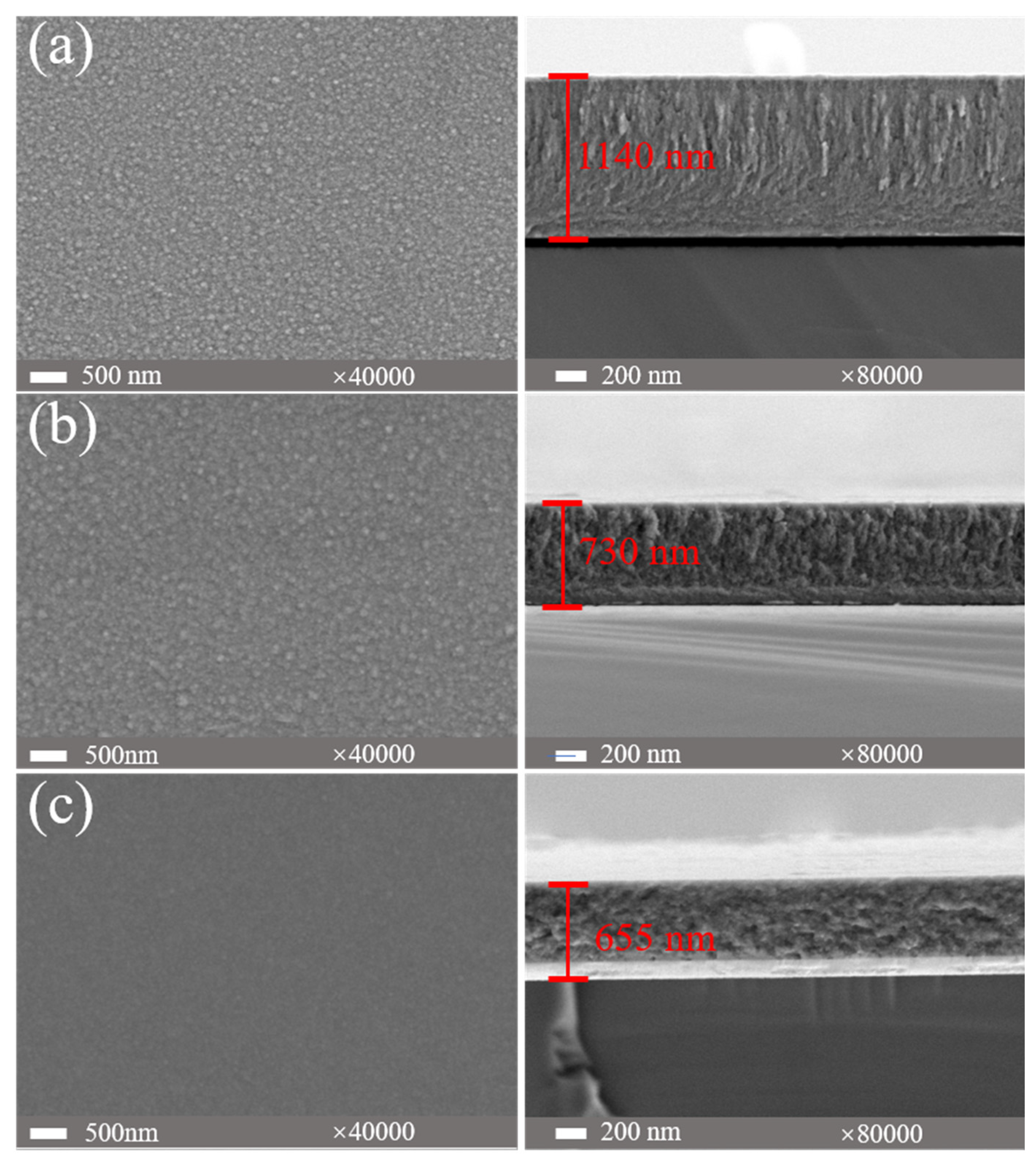
Figure 6.
Elemental distribution of (AlFeCoNi)Cx HECFs deposited at Fc=3 sccm. 3D reconstruction of an APT dataset, and atom maps of mixed, Al, Fe, Co, Ni and C.
Figure 6.
Elemental distribution of (AlFeCoNi)Cx HECFs deposited at Fc=3 sccm. 3D reconstruction of an APT dataset, and atom maps of mixed, Al, Fe, Co, Ni and C.
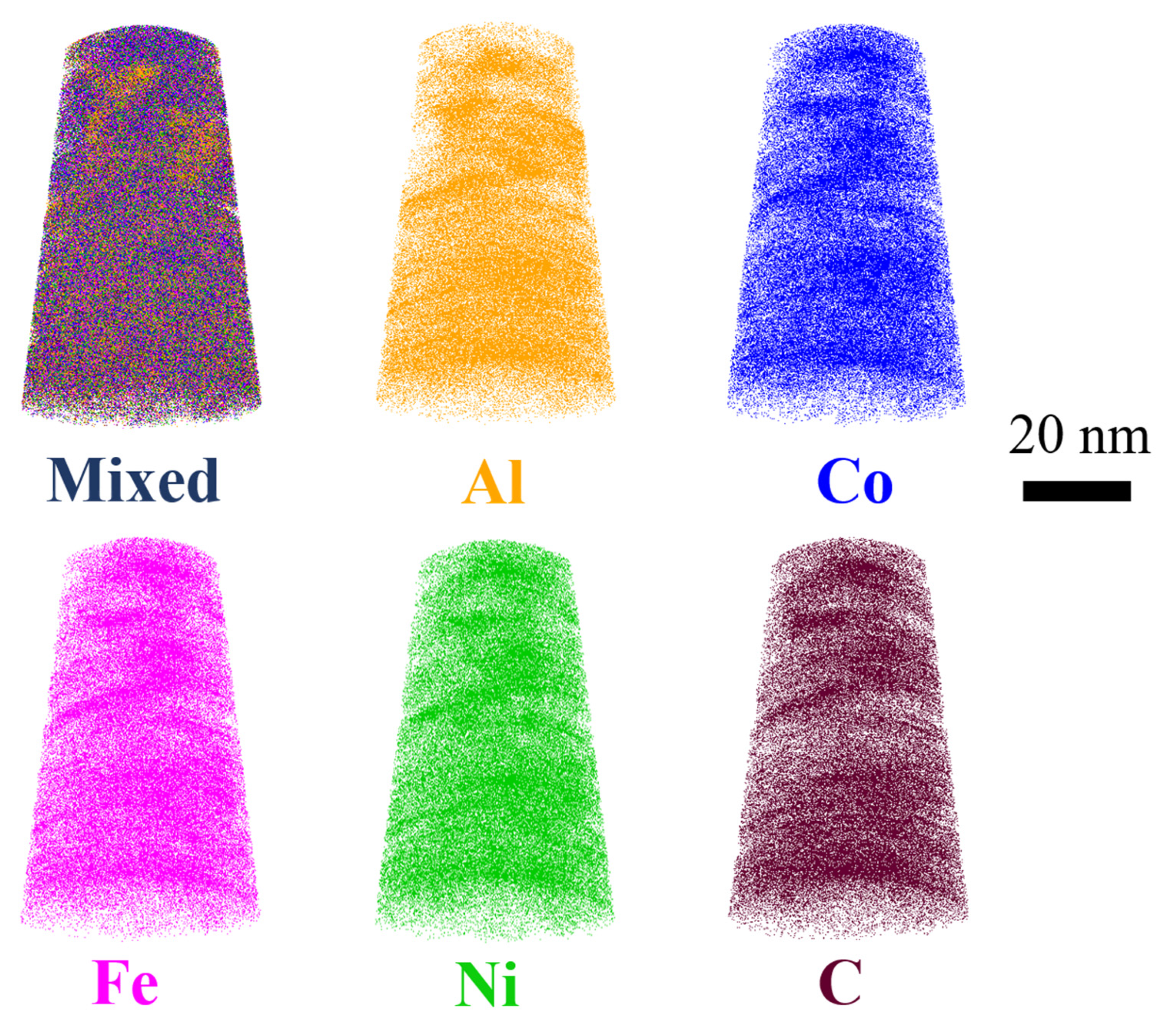
Figure 7.
TEM images of (AlFeCoNi)Cx HECFs deposited at Fc=3 sccm, (a) low magnified images, (b), (d) and (e) are high resolution images, (c) selected area electron diffraction pattern.
Figure 7.
TEM images of (AlFeCoNi)Cx HECFs deposited at Fc=3 sccm, (a) low magnified images, (b), (d) and (e) are high resolution images, (c) selected area electron diffraction pattern.
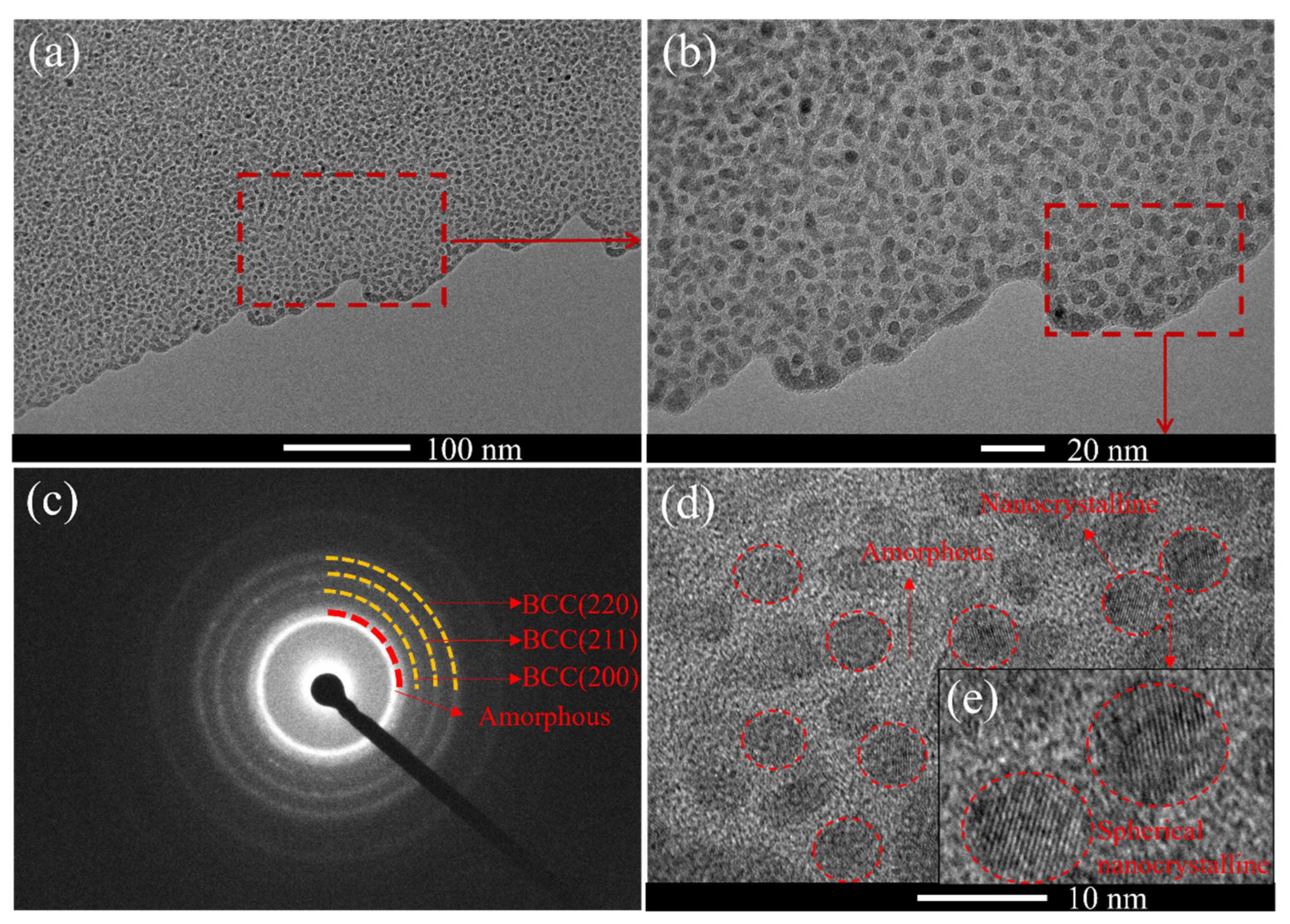
Figure 8.
(a) Friction coefficient curves, (b) wear rates of (AlFeCoNi)Cx HECFs deposited at different carbon flow rates.
Figure 8.
(a) Friction coefficient curves, (b) wear rates of (AlFeCoNi)Cx HECFs deposited at different carbon flow rates.
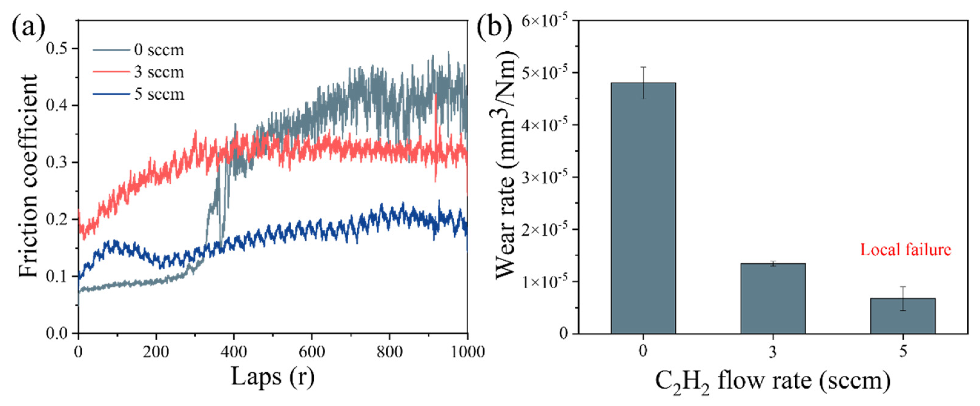
Figure 9.
Wear track profiles and morphologies of (AlFeCoNi)Cx HECFs deposited at Fc = (a) 0 sccm, (b) 3 sccm, and (c) 5 sccm.
Figure 9.
Wear track profiles and morphologies of (AlFeCoNi)Cx HECFs deposited at Fc = (a) 0 sccm, (b) 3 sccm, and (c) 5 sccm.
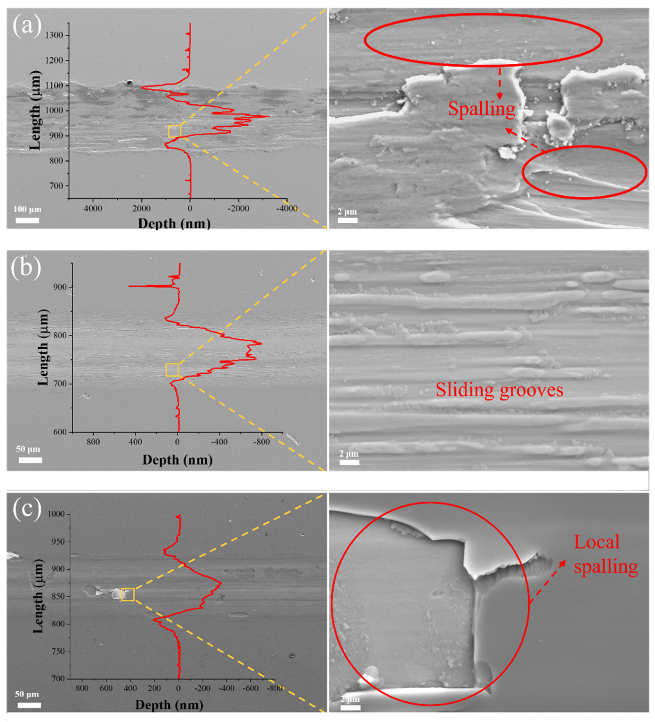
Figure 10.
Potentiodynamic polarization curves of bare 304 SS and the (AlFeCoNi)Cx HECFs in 3.5 wt% NaCl.
Figure 10.
Potentiodynamic polarization curves of bare 304 SS and the (AlFeCoNi)Cx HECFs in 3.5 wt% NaCl.
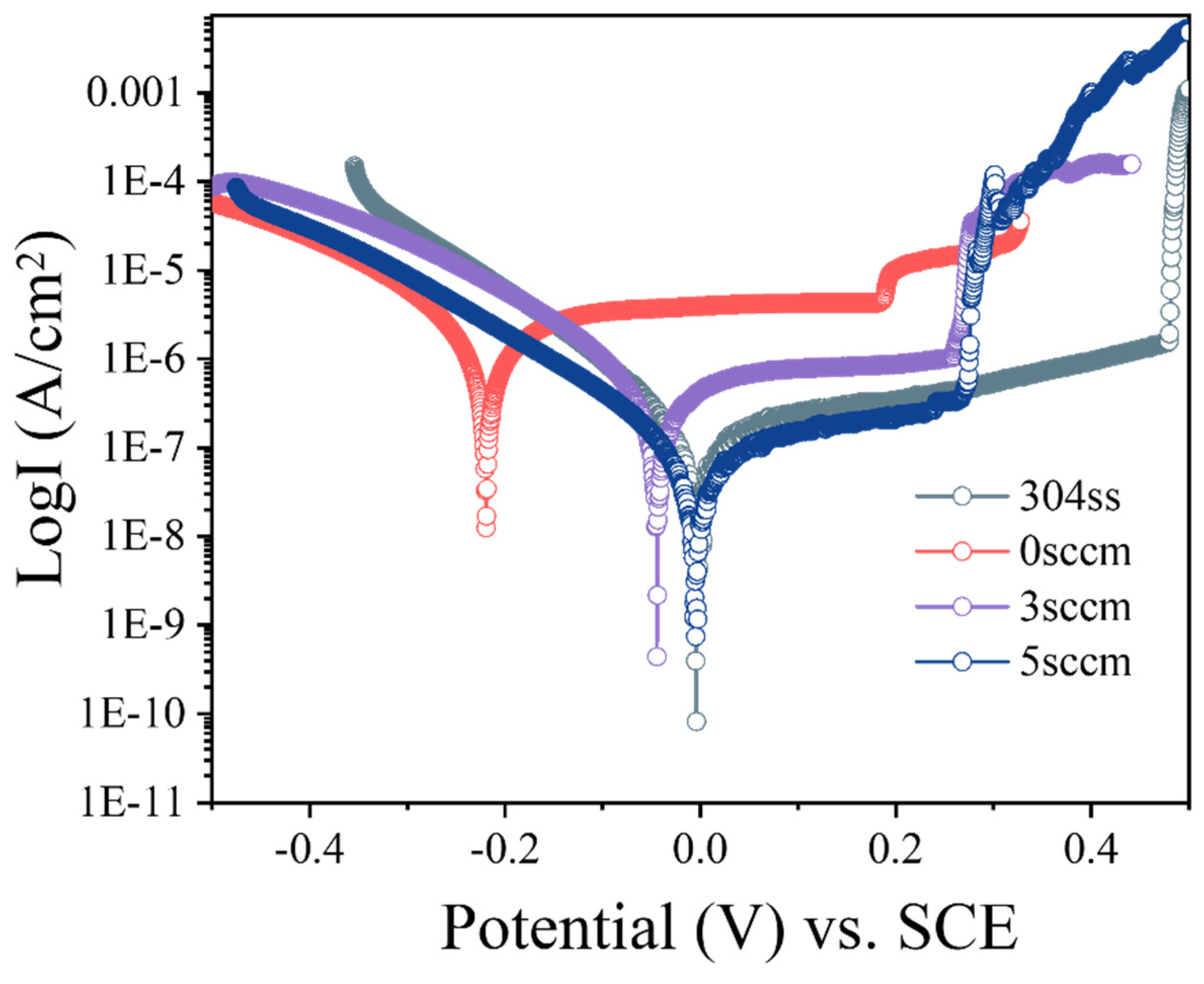
Figure 11.
(a) Nyquist plots from EIS data of 304 SS and the (AlFeCoNi)Cx HECFs. (b) Equivalent circuit model of the substrate and HECFs coated substrate.
Figure 11.
(a) Nyquist plots from EIS data of 304 SS and the (AlFeCoNi)Cx HECFs. (b) Equivalent circuit model of the substrate and HECFs coated substrate.
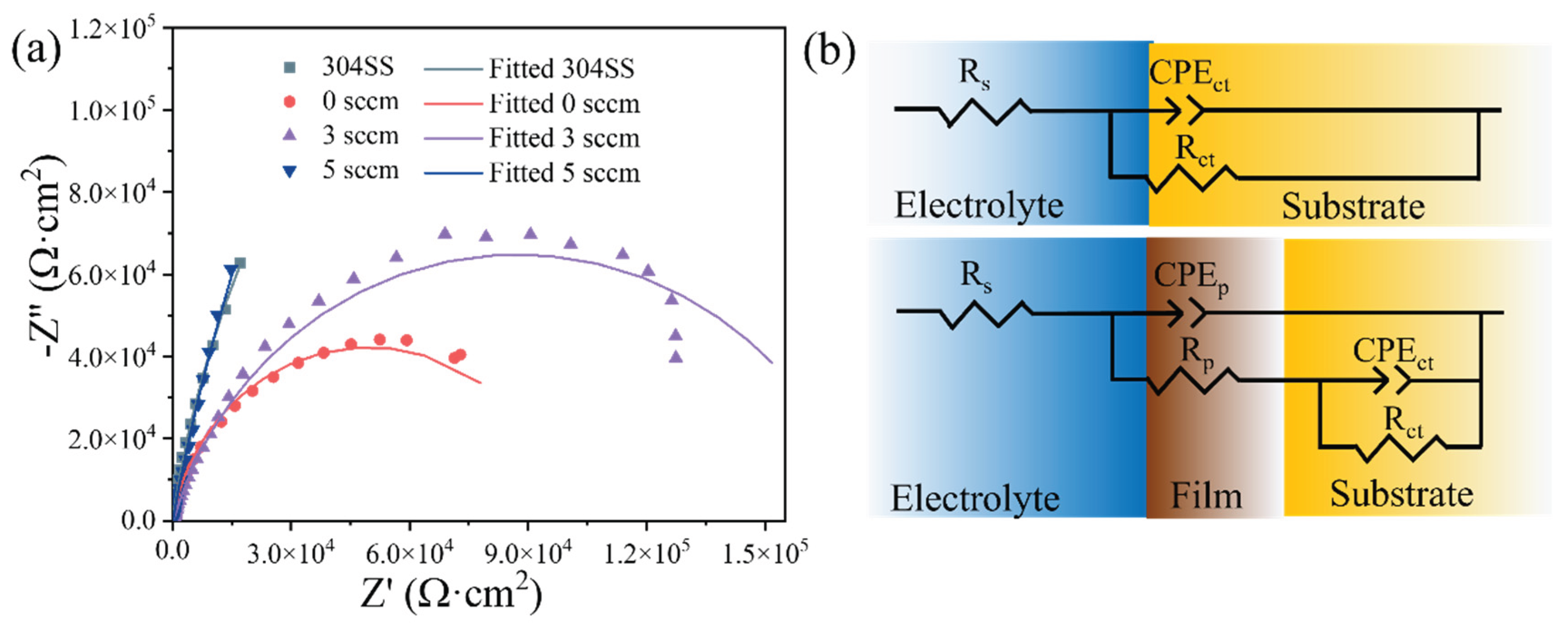

Table 1.
Deposition parameters of the (AlFeCoNi)Cx HECFs.
| Process parameter | Values |
| Base pressure (Pa) | 1×10⁻³ |
| Working pressure (Pa) | 0.9 |
| HPPMS power (V-μs-Hz) | 800-150-200 |
| Argon flow (sccm) | 40 |
| Acetylene flow (sccm) | 0, 3, 5 |
| Deposition time (min) | 30 |
| Deposition temperature | Room temperature |
| Substrate bias voltage (V) | -50 |
| Substrate-target distance (mm) | 80 |
Table 2.
The corrosion potential (Ecorr) and corrosion current density (Icorr) for the HECFs-coated and uncoated 304 SS.
Table 2.
The corrosion potential (Ecorr) and corrosion current density (Icorr) for the HECFs-coated and uncoated 304 SS.
| Samples | 304 SS | 0 sccm | 3 sccm | 5 sccm |
| Ecorr (VSCE) | -0.004 | -0.222 | -0.045 | -0.004 |
| Icorr (A/cm2) | 1.23 E-07 | 1.62 E-06 | 4.03 E-07 | 7.16 E-08 |
Table 3.
Electrochemical impedance parameters obtained by fitting EIS data of the (AlFeCoNi)Cx HECFs and 304 SS substrate.
Table 3.
Electrochemical impedance parameters obtained by fitting EIS data of the (AlFeCoNi)Cx HECFs and 304 SS substrate.
|
Samples/ Parameter |
Rs (Ω·cm2) |
Rp (Ω·cm2) |
CPEp (sn·Ω-1·cm-2) |
Rct (Ω·cm2) |
CPEct (sn·Ω-1·cm-2) |
χ2 | ||
| 0 sccm | 5.3 | 1110 | 2.0×10⁻⁵ | 98399 | 1.01×10⁻⁵ | 0.0030 | ||
| 3 sccm | 5.4 | 1154 | 5.2×10⁻⁶ | 174170 | 1.1×10⁻⁵ | 0.0026 | ||
| 5 sccm | 4.9 | 1890 | 8.0×10⁻⁶ | 1834200 | 3.1×10⁻⁶ | 0.0589 | ||
| 304SS | 4.8 | - | - | 534500 | 1.1×10⁻⁴ | 0.0045 | ||
Disclaimer/Publisher’s Note: The statements, opinions and data contained in all publications are solely those of the individual author(s) and contributor(s) and not of MDPI and/or the editor(s). MDPI and/or the editor(s) disclaim responsibility for any injury to people or property resulting from any ideas, methods, instructions or products referred to in the content. |
© 2025 by the authors. Licensee MDPI, Basel, Switzerland. This article is an open access article distributed under the terms and conditions of the Creative Commons Attribution (CC BY) license (http://creativecommons.org/licenses/by/4.0/).
Copyright: This open access article is published under a Creative Commons CC BY 4.0 license, which permit the free download, distribution, and reuse, provided that the author and preprint are cited in any reuse.


