
Submitted:
11 August 2025
Posted:
13 August 2025
You are already at the latest version
Abstract
A physical unclonable function (PUF) leverages the unclonable random variations in device behavior due to defects incurred during manufacturing to produce a unique “biometric” that can be used for authentication. Here, we show that the threshold current for the switching of a magnetic tunnel junction via spin transfer torque is sensitive to the nature of structural defects introduced during manufacturing and hence can be the basis of a PUF. We use micromagnetic simulations to study the threshold currents for six different defect morphologies at two different temperatures to establish the viability of a PUF. We also derive the challenge-response set at the two different temperatures to calculate the inter- and intra-Hamming distances for a given challenge.
Keywords:
physically unclonable functions
; spin transfer torque
; variability of threshold currents
; structural defects
; magnetic tunnel junctions
1. Introduction
Mobile and embedded devices are increasingly called upon to authenticate or be authenticated by another party for trust. These devices include cell phones that are used routinely for bank transactions, and medically implanted devices that form an integral part of acute care and patient monitoring. The usual approach to providing protection against unauthorized use, data interception, etc. is to place a secret key in a nonvolatile electrically erasable programmable read-only memory (EEPROM) or battery-backed static random access memory (SRAM) and use hardware cryptographic operations such as digital signatures or encryption for authentication [1]. This approach is expensive both in terms of design area and power consumption [1]. Furthermore, non-volatile memory is often vulnerable to invasive attacks that can be thwarted only using active tamper detection/prevention circuitry which are continually powered [1] and hence inappropriate for edge devices or Internet of Things where energy is a premium and continual powering is prohibitive. Physical unclonable functions (PUFs), on the other hand, are a promising alternative that enables authentication and secret key storage via the physical characteristics of a device which are unpredictable and impossible to anticipate, duplicate or hack.
2. PUFs Based on Magnetic Tunnel Junctions
A popular implementation of PUFs involves magnetic tunnel junctions (MTJs) [2,3,4,5,6,7,8] which are essentially binary switches with two resistance states – “high” and “low.” An MTJ is a three-layered structure with the two outer layers ferromagnetic and the middle layer a non-magnetic insulator through which spin-dependent tunneling of electrons takes place between the two ferromagnetic layers. Each layer is shaped like an elliptical disk and the magnetization of each will align along the so-called “easy axis” which is along the major axis of the ellipse – either pointing to the left or to the right [see Figure 1] (this makes the magnetization “bistable”). One layer is permanently magnetized in one of the two directions along the major axis and is called the hard layer while the other is the soft layer whose magnetization can be switched from right to left, or vice versa, by passing a spin-polarized current pulse of the correct polarity between the two layers. The MTJ resistance is high when the magnetizations of the two ferromagnetic layers are antiparallel and low when they are parallel. Thus, flipping the magnetization of the soft layer results in switching the resistance of the MTJ from high to low, or vice versa.
2.1. Threshold Current Based PUF
The minimum (spin-polarized) charge current (threshold current) needed for switching depends on the current pulse width, degree of spin polarization, and various MTJ soft layer parameters such as size, ellipticity, material composition, etc. Even if we keep all these parameters fixed, the threshold current will vary because of unintentional defects introduced in the soft layer during fabrication. Since these defects are unclonable and unpredictable, the threshold current is also unclonable and unpredictable. Thus, if we pass a current of fixed amplitude and duration through a number of nominally identical MTJs that have different (random) defect morphologies, as shown in Figure 2, some will switch and some will not, and which ones will switch is unpredictable and unclonable. This can be the basis of a PUF. Such a PUF is usually superior to many other types of PUFs, such as memristor-based PUFs [9], because the defects are extremely stable.
Let us say that we have 8 MTJs which are all initialized to the low resistance state with a global magnetic field. We then pass a current of amplitude (of the correct polarity) for a duration through all of them as shown in Figure 2. Let us say that because of the defects in the soft layers of the MTJs, devices 3, 5, and 8 switch to the high resistance state because their threshold currents (which depend on the defect morphology) are below . We will denote the resistance of the MTJ by a single bit – 0 for low resistance and 1 for high resistance. In this specific case, the output string representing the resistance states of the 8 MTJs will be 00101001 where the n-th bit represents the resistance state of the n-th MTJ after current injection.
Let us now say that we increase the current pulse amplitude to 1.2. This time MTJs 1, 2, 3, 5, and 8 switch because their threshold currents are below 1.2. The corresponding output bit stream representing the final resistance states will be 11101001. Thus, each current value produces a different output bit stream. This forms a set of “challenge” (current pulse amplitude) and the corresponding “response” (output bit streams). This set is specific to this particular unit and is a fingerprint or biometric of that unit, which is unpredictable and unclonable. A different unit with different unpredictable manufacturing defects will produce a different challenge-response set. It is impossible to predict what the response to a specific challenge will be for a given unit and it is impossible to intentionally fabricate two units with the exact same challenge-response set since the defects are uncontrollable. This is the basis of a PUF.
Instead of changing the current pulse amplitude, one can change the current pulse width or duration, while keeping the amplitude fixed. This will also have a similar effect and could be the basis of a PUF. Here, we will study the amplitude challenge rather than the pulse width challenge.
To proceed further, we will have to evaluate the threshold currents in nominally identical soft layers which are all made of cobalt and all shaped like elliptical disks of major axis 100 nm, minor axis 90 nm and average thickness 3 nm. However, they have different defect morphologies associated with voids, random thickness variations, etc. We will consider one pristine (defect-free) soft layer and five defective soft layers, each having a different type of defect. These are shown in Figure 3.
To calculate the threshold current at room temperature, we have to calculate the probability of the magnetization flipping as a function of the injected current amplitude, when the current pulse width is fixed at 3 ns. For this purpose, the magnetization of the soft layer is initially aligned along one direction, say the –y-direction as shown in Figure 3, with an external magnetic field. Next, spin polarized current with a majority of the spins polarized along the +y-direction, is injected perpendicular to the surface. Flipping takes place when the magnetization aligns close to the +y-direction and the normalized y-component of the magnetization exceeds 0.9, regardless of what the x- and z-components are. We simulate the time evolution of the magnetization which is governed by the Landau-Lifshitz-Gilbert equation and track the temporal evolution of the magnetization for a duration of 3 ns (current pulse width) in the presence of thermal noise. This is accomplished with the micromagnetic simulator MuMax3 [10]. The ambient temperature is assumed to be 300 K. The thermal noise makes the switching trajectories random. Hence we generate 100 trajectories and the probability of switching is defined as the fraction of the trajectories that at the end of the 3 ns show a y-component of normalized magnetization greater than or equal to 0.9. We calculate these probabilities for different current pulse amplitude and for a fixed pulse width of 3 ns. They are calculated for the six different defect morphologies shown in Figure 3 and the resulting plots are shown in Figure 4. These morphologies are very similar to the ones studied in ref. [11] and are frequently found in fabricated nanomagnets.
Figure 4 shows that the probabilities do not change abruptly from near-zero to near-100% as we increase the current amplitude. That makes it difficult to define a “threshold current”. Absent any better definition, we define the threshold current as the current that results in a 80% or more likelihood of flipping. Clearly, the threshold current depends on the defect morphology.
3. Materials and Methods
For the purpose of simulation, we map the different defect morphologies on to the MuMax3 software package using a uniform mesh size of 2.8 nm × 3.1 nm × 1 nm. There are 32 × 32 × 4 cells giving a total area of 90 nm × 100 nm × 4 nm, and use a time step of 0.09 ps. An effective magnetic field due to noise is introduced as [12]
where is the Gilbert damping constant, is the universal gyromagnetic factor, () are three uncorrelated Gaussians of zero mean and unit standard deviation, is the nanomagnet volume, k is the Boltzmann constant, T is the absolute temperature, and is the time step of the simulation (0.09 ps). The magnet material is assumed to be cobalt and we use its material parameters. The current is spin polarized and we assume the spin polarization percentage to be 30%.
We track the magnetization components (normalized to the saturation magnetization of cobalt) , and as a function of time, starting with the initial condition = 0 and = -1. The simulation is continued for 3 ns and the final state of is noted. If it is greater than or equal to 0.9, we conclude that switching has taken place.
We repeat the simulation 100 times to generate 100 switching trajectories. Because of the presence of thermal noise, the final state of and hence the switching outcome is different for different trajectories. The probability of switching is the fraction of trajectories that result in successful switching after 3 ns of current injection, i.e., the final . Since we have 100 trajectories, the accuracy in calculating the switching probability is 1%. This is adequate since, as we will see later, the difference between the switching probabilities at the threshold current for any given defect morphology is more than 1%.
We calculate the switching probability as a function of current amplitude for all six morphologies shown in Figure 3 and plot them in Figure 4. This allows us to determine the threshold currents which are tabulated in Table 1. Note that the plots in Figure 4 are not monotonic because of the presence of thermal noise.
As already mentioned, we define the threshold current as that which ensures that switching occurs with 80% probability. If we increase this to a higher percentage, we will just have a higher threshold current in all cases. What we are looking for, however, is not so much the exact value of the threshold current but whether the threshold is different for different defect morphologies since that enables a PUF.
4. Results and Discussion
4.1. PUF Behavior
Let us consider a unit consisting of just three MTJs instead of the eight shown in Figure 2. We assume that MTJ1 is defect-free (threshold current = 2.75 mA), MTJ2 has a defect of type (threshold current = 2.78 mA) and MTJ3 has a defect of type (threshold current = 3.26 mA), all introduced during fabrication. Let us say that we pass a current of 2.9 mA which exceeds the threshold of MTJ 1 and 2 significantly to the point that their switching probabilities are ∼90%, but it falls short of the threshold current of MTJ3 whose switching probability at that current is only ∼55%. This current input can be considered the “challenge” and the “response” bit stream in this case will be 110, indicating that the first two MTJs switch with high probability while the last fails to switch almost half of the time.
Let us take another unit where the defect morphologies of MTJ2 and MTJ3 are switched. In that case, for the same current injection, the response bit stream will be 101.
We can generate the response bit streams for all possible combinations of defect morphologies in a 3-MTJ unit (each MTJ has a different defect ), following the convention that the first bit in the response bit stream corresponds to the response of the first MTJ, the second to the second MTJ, and the third to the third MTJ. Using this convention, we can generate the response bit streams for six different 3-MTJ units each having a different defect distribution. This is shown in Table 2.
It is easy to see that if the challenge current had been 2.76 mA, then the response bit stream would have been [100], [100], [010], [001], [001], [010]. Thus, by using different challenges and the corresponding responses, we can generate a challenge-response table which will depend on the defect morphologies and hence will be a fingerprint of the specific unit under consideration. Since the defect morphologies are unpredictable, unknown and unclonable, the challenge-response table is also unpredictable, unknown and unclonable. One will have to measure the response to each challenge and establish the unique challenge-response characteristic of any unit which then becomes a biometric of that unit and enables a PUF.
4.2. Inter-Hamming Distance
The inter-Hamming distance (IHD) is defined as the number of positions where the bits in the response bit stream are different for two different units divided by the number of bits, averaged over all possible pairs. We can see from Table 2, that the Hamming distance between units 1 and 2 is 2/3, between units 1 and 3 is 0, between units 1 and 4 is 2/3, between units 1 and 5 is 2/3, and between 1 and 6 is also 2/3.
Similarly, between units 2 and 3, it is 2/3, between 2 and 4 it is 0, between 2 and 5 it is 2/3 and between 2 and 6 it is 2/3.
We can go on with the other combinations and then average over all combinations to find that the IHD is 8/15 or 0.533. This is only true for the challenge current of 2.9 mA and will change for a different challenge. The ideal IHD for a PUF is 0.5 [2].
In this example, we arbitrarily assumed that no two MTJs in a unit have the same defect morphology. In reality, this restriction should not exist and the defect morphology can be repeated in two or even all three MTJs. In that case, we will have 33 = 27 possible combinations (27 different units) and then the IHD will have to be computed by comparing the response bit streams of [n = 26], i.e. 351 pairs. This process leads to an IHD = 0.479 for the challenge current of 2.9 mA. A different challenge current will, of course, produce a different IHD.
4.3. Sensitivity to Temperature and Intra-Hamming Distance
We recalculated the switching probability as a function of current at an increased temperature of 330 K to examine if temperature has an effect on the challenge-response behavior. A strong effect will be undesirable since then the challenge-response set will no longer be a unique fingerprint of the defect morphology. The measure of uniqueness is the intra-Hamming distance which is the number of positions where the response bits to the same challenge are different for the same unit under two different conditions, such as different temperatures, divided by the number of bits in the response stream. Ideally, the intra-Hamming-distance should be zero, indicating that the challenge-response behavior of the PUF is invariant and therefore it can act as a true fingerprint or biometric.
The switching probability versus current plot at 330 K is shown in Figure 5. The threshold currents do change somewhat for a 30 Kelvin increase in temperature. We tabulate the threshold currents at 330 K temperature in Table 3. Note that the increase in temperature can either increase or decrease the threshold current depending on the defect morphology.
If we now use the same 3-MTJ unit as before and use the same challenge current of 2.9 mA, then the response bit streams would be exactly the same as in Table 2. This is because the sensitivity of the threshold current (of any defect morphology) to reasonable temperature variations, albeit non-zero, is too weak to change the challenge-response set for the 2.9 mA challenge. Hence, the intra-Hamming-distance in this case is zero, attesting to the uniqueness of the challenge-response set for a 2.9 mA current challenge. This may not hold for a different challenge current.
5. Conclusion
We have shown that the threshold current for switching the magnetization of the soft layer of a magnetic tunnel junction via spin transfer torque depends sensitively on the nature of defect(s) introduced during manufacturing. This feature can be exploited to implement a physical unclonable function (PUF). We have also calculated the inter- and intra-Hamming distances for a given challenge.
If the soft layer of the MTJ is made magnetostrictive, then its magnetization can be flipped with electrically generated strain [13]. This is more energy-efficient than switching with spin transfer torque which is the method discussed here. More importantly, the threshold strain for strain-mediated switching is even more sensitive to defect morphologies [11] and hence may enable an even stronger PUF. This is left for future study.
Acknowledgments
Huber was supported by a Research Experience for Undergraduates (REU) grant [REU Site in Magnetics] from the US National Science Foundation (grant number DMR-2349694). High Performance Computing resources provided by the High Performance Research Computing (HPRC) core facility at Virginia Commonwealth University (https://hprc.vcu.edu) were used for conducting the research reported in this work.
References
- Herder, C.; Yu, M-D.; Farinaz, K. and Devadas, S. Physical Unclonable Functions and Applications: A Tutorial. Proc. IEEE 2014, 102, 1126. [CrossRef]
- Chen, H.; Song, M.; Guo, Z.; Li, R.; Zou, Q.; Luo, S.; Zhang, S.; Luo, Q.; Hong, J. and You, L. Highly Secure Physically Unclonable Cryptographic Primitives Based on Interfacial Magnetic Anisotropy. Nano Lett. 2018, 18, 7211. [CrossRef] [PubMed]
- Cao, Z. et al. Reconfigurable Physical Unclonable Function Based on Spin-Orbit Torque Induced Chiral Domain Wall Motion. IEEE Elec. Dev. Lett. 2021, 42, 597. [CrossRef]
- Kumar, A.; Sahay, S. and Suri, M. Switching-Time Dependent PUF Using STT-MRAM. 2018, 31th International Conference on VLSI Design and 2018 17th International Conference on Embedded Systems (IEEE).
- Das, J.; Kevin, S., Srinath, R.; Drew, B. and Bhanja, S. MRAM PUF: A novel geometry based magnetic PUF with integrated CMOS. IEEE Trans. Nanotechnol. 2015, 14, 436–443. [CrossRef]
- Zhang, L.; Fong, X.; Chang, C. H.; Kong, Z. H. and Roy, K. Feasibility study of emerging non-volatile memory based physical unclonable functions. IEEE 6th International Memory Workshop, 2014, pp. 1-4.
- Marukame, M.; Tanamoto, T. and Mitani, Y. Extracting physically unclonable function from spin transfer switching characteristics in magnetic tunnel junctions. IEEE Trans. Magn. 2014, 50, 1–4. [CrossRef]
- Vatajelu, E.I.; Natale, G.D.; Barbareschi, M.; Torres, L.; Indaco, M. and Prinetto, P. STT-MRAM-based PUF architecture exploiting magnetic tunnel junction fabrication-induced variability. ACM Journal on Emerging Technologies in Computing Systems (JETC) 2016, 13, 5. [CrossRef]
- Rose, G. S.; McDonald, N.; Yan, L-K. and Wysocki, B. A write-time based memristive puf for hardware security applications. Proc. IEEE/ACM Int. Conf. Comput.-Aided Design, 2013, pp. 830–833.
- https://www.ugent.be/we/solidstatesciences/dynamat/en/mumax.
- Winters, D.; Abeed, M. A.; Sahoo, S.; Barman, A. and Bandyopadhyay, S. Reliability of magnetoelastic switching of nonideal nanomagnets with defects: A case study for the viability of straintronic logic and memory. Phys. Rev. Appl. 2019, 12, 034010. [CrossRef]
- Brown Jr. W. F. Thermal Fluctuations of a Single-Domain Particle. Phys. Rev. 1963, 130, 1677. [CrossRef]
- Bandyopadhyay, S. Magnetic Straintronics An Energy-Efficient Hardware Paradigm for Digital and Analog Information Processing, Synthesis Lectures on Engineering, Science and Technology, Springer Nature, New York, 2022.
Figure 1.
The structure of a magnetic tunnel junction and the magnetization orientations in the two resistance states.
Figure 1.
The structure of a magnetic tunnel junction and the magnetization orientations in the two resistance states.
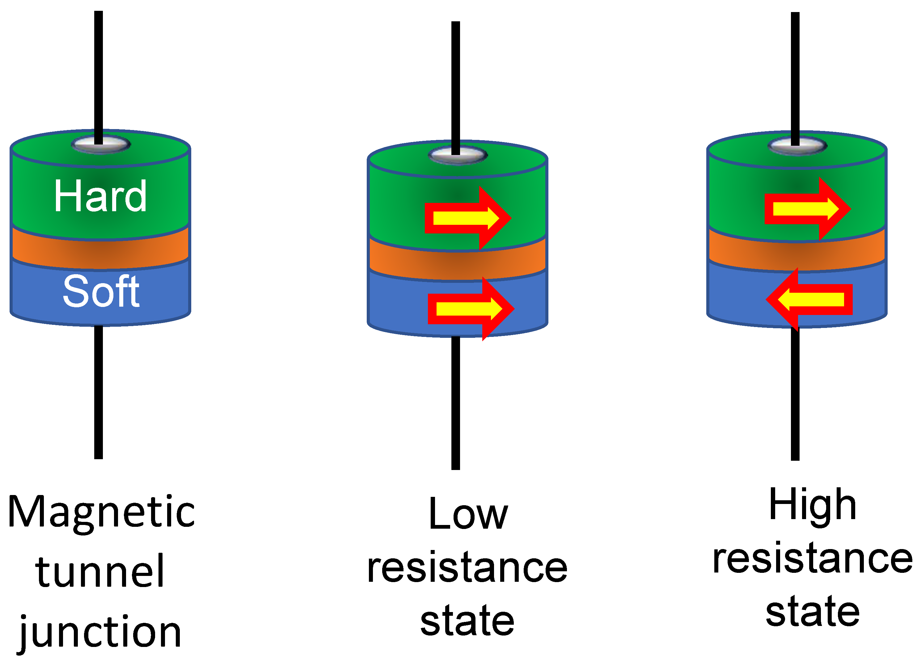
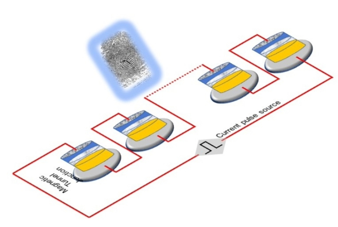
Figure 2.
A physical unclonable function (PUF) built with nominally identical MTJs with different random and unclonable defect morphologies connected in series and injected with the same spin-polarized current.
Figure 2.
A physical unclonable function (PUF) built with nominally identical MTJs with different random and unclonable defect morphologies connected in series and injected with the same spin-polarized current.
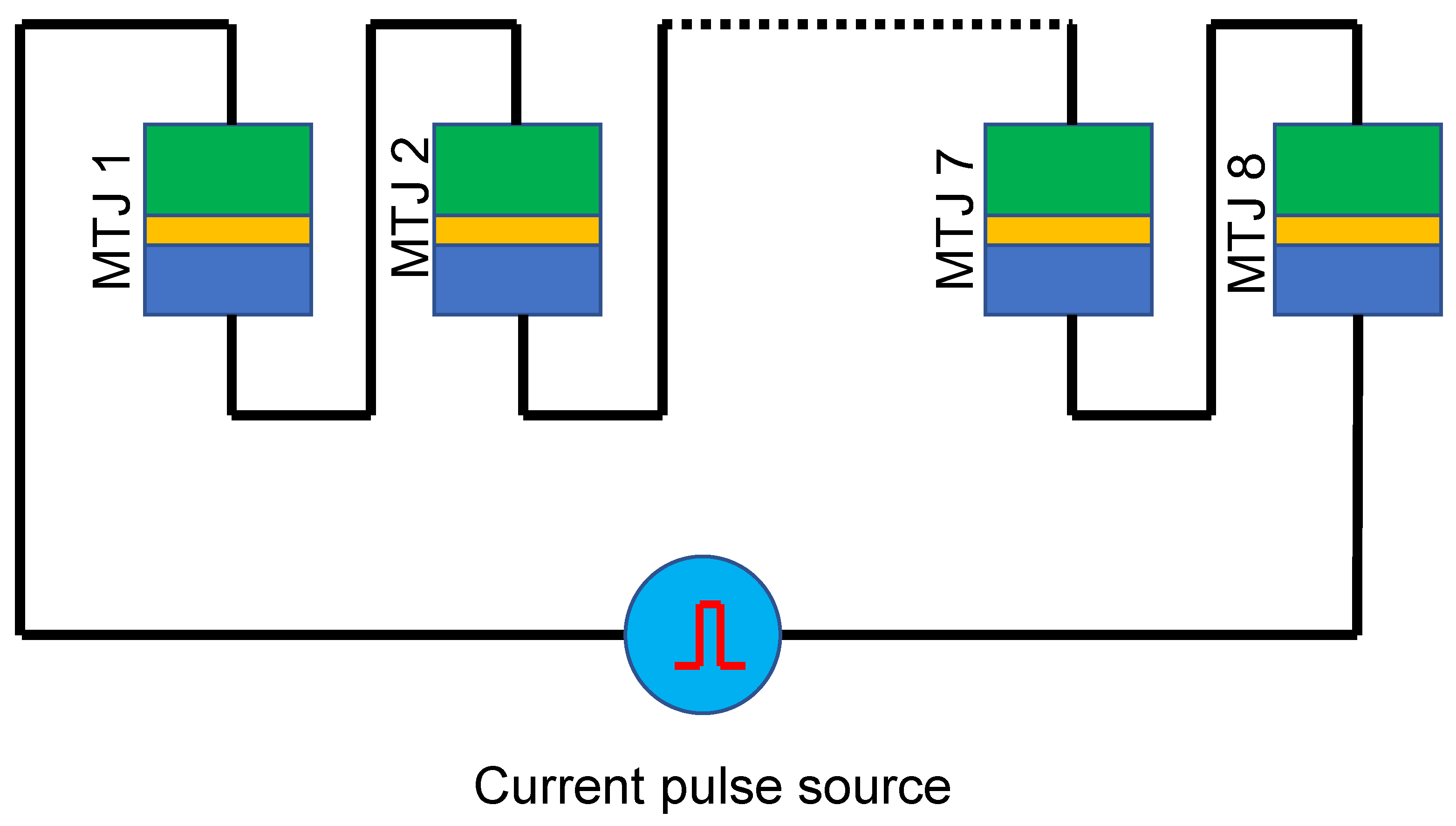
Figure 3.
Different types of defects in an elliptical cobalt soft layer of major axis 100 nm, minor axis 90 nm and average thickness 3 nm. is a defect-free pristine elliptical soft layer; has a 5-nm diameter hole in the center that is 2 nm deep; has one-half thicker than the other, with the thicker half 4 nm and the thinner half 2 nm, which makes the step size 2 nm; has a 10-nm wide rim that rises 1 nm above the surface; has a 5-nm diameter rivet that rises 1 nm above the surface, while has through-hole with a diameter of 5 nm.

Figure 4.
Switching probability as a function of current pulse amplitude (pulse width = 3 ns) at room temperature (300 K) for different defect morphologies. The threshold current is defined as that where the switching probability becomes 80%. We also assume that switching occurs if the magnetization component along the major axis of the elliptical nanomagnet reaches 0.9. The vertical dashed lines indicate the values of the threshold currents for different defect morphologies.
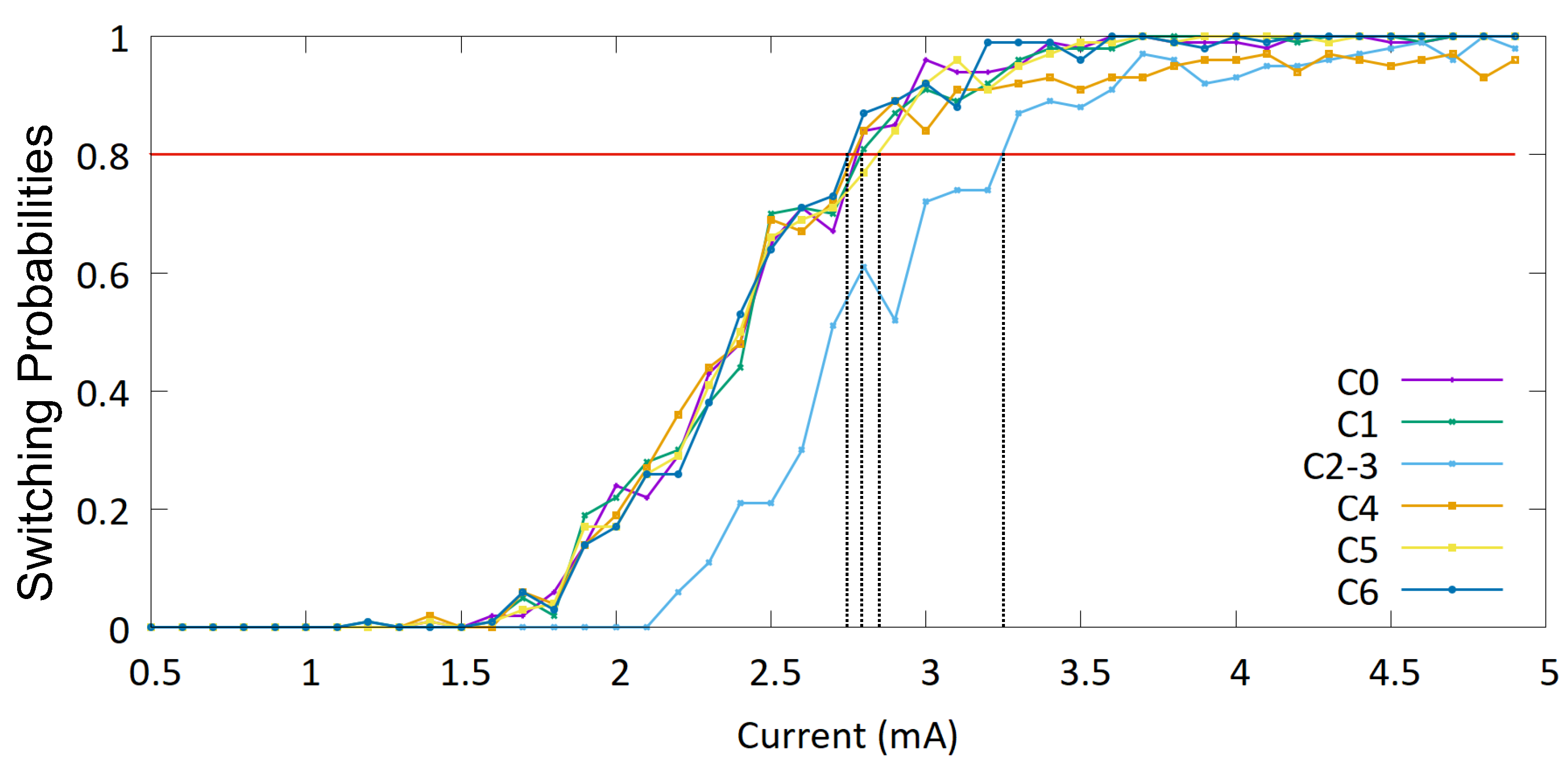
Figure 5.
Switching probability as a function of current pulse amplitude (pulse width = 3 ns) at an increased temperature (330 K) for different defect morphologies. The threshold current is defined as that where the switching probability becomes 80%. We also assume that switching occurs if the magnetization component along the major axis of the elliptical nanomagnet reaches 0.9. The vertical dashed lines indicate the values of the threshold currents for different defect morphologies.
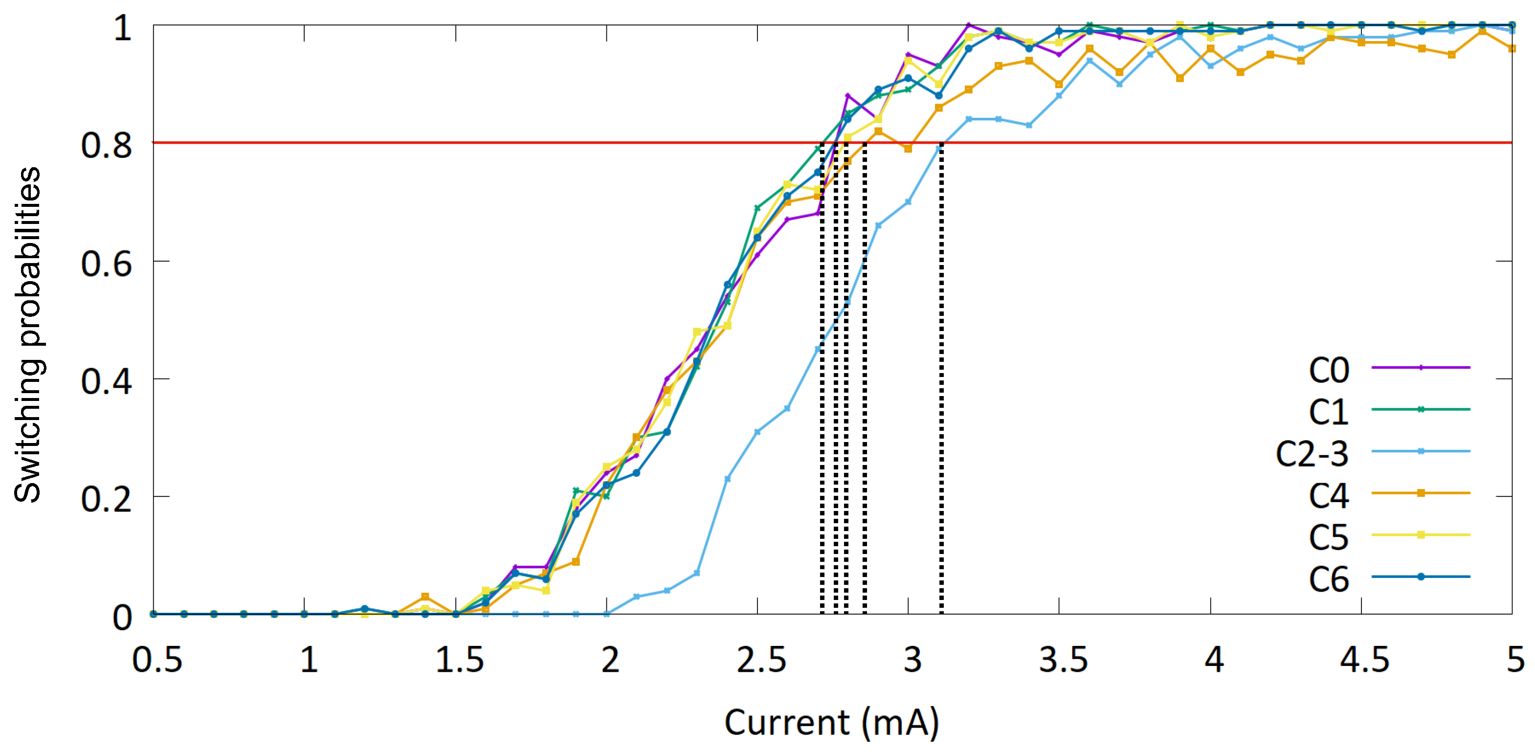

Table 1.
Threshold currents for different defect morphologies at 300 K temperature.
| Defect | Threshold current (mA) | Threshold current density (A/m2) |
|---|---|---|
| 2.75 | 3.89×10¹¹ | |
| 2.78 | 3.93×10¹¹ | |
| 3.26 | 4.61×10¹¹ | |
| 2.78 | 3.93×10¹¹ | |
| 2.82 | 3.98×10¹¹ | |
| 2.78 | 3.93×10¹¹ |
Table 2.
Response bit streams under a current injection challenge of 2.9 mA for six different 3-MTJ units with different distribution of the defect morphologies at 300 K temperature.
Table 2.
Response bit streams under a current injection challenge of 2.9 mA for six different 3-MTJ units with different distribution of the defect morphologies at 300 K temperature.
| Defect distribution | Response bit stream |
|---|---|
| Unit 1: | 110 |
| Unit 2: | 101 |
| Unit 3: | 110 |
| Unit 4: | 101 |
| Unit 5: | 011 |
| Unit 6: | 011 |
Table 3.
Threshold currents for different defect morphologies at 330 K temperature.
| Defect | Threshold current (mA) | Threshold current density (A/m2) |
|---|---|---|
| 2.75 | 3.89×10¹¹ | |
| 2.72 | 3.84×10¹¹ | |
| 3.12 | 4.41×10¹¹ | |
| 2.82 | 3.99×10¹¹ | |
| 2.80 | 3.95×10¹¹ | |
| 2.75 | 3.88×10¹¹ |
Disclaimer/Publisher’s Note: The statements, opinions and data contained in all publications are solely those of the individual author(s) and contributor(s) and not of MDPI and/or the editor(s). MDPI and/or the editor(s) disclaim responsibility for any injury to people or property resulting from any ideas, methods, instructions or products referred to in the content. |
© 2025 by the authors. Licensee MDPI, Basel, Switzerland. This article is an open access article distributed under the terms and conditions of the Creative Commons Attribution (CC BY) license (http://creativecommons.org/licenses/by/4.0/).
Copyright: This open access article is published under a Creative Commons CC BY 4.0 license, which permit the free download, distribution, and reuse, provided that the author and preprint are cited in any reuse.


