
Submitted:
17 July 2025
Posted:
18 July 2025
You are already at the latest version
Abstract
This paper introduces a speed sensorless Dual Field-Oriented Control (DFOC) strategy for induction motors (IM). DFO combines the advantages or rotor-and stator-field orienta-tion to significantly reduce the parameter sensitivity of the control regarding the generation of the converter control variable. A simplified structure is also proposed, using only two regulators for the flux and speed control, eliminating the two current regulators. Related to sensorless control, the classical adaptation mechanism within the MRAS (Model Reference Adaptive System) observer has been replaced with artificial intelligence (AI)-based approaches. Specifically, artificial neural networks (ANN) and recurrent neural networks (RNN) are employed for rotor speed estimation. The effectiveness of the proposed sensor-less control scheme is validated through both simulation and real-time implementation. The results demonstrate that ANN- and RNN-based observers, as deep learning models, provide reliable and accurate rotor speed estimation under various operating conditions.
Keywords:
artificial intelligence
; deep learning
; induction machine
; field-oriented control
; sensorless control
1. Introduction
In adjustable AC drive applications, vector control is mainly used due to its exceptional dynamic performance in terms of response to rapid speed and torque variations. This is achieved by the independent control of the motor flux and torque, based on the analogy with the DC machine, where the magnetization is controlled by the excitation current, while the motor torque is determined by the armature current. For the AC machines, the stator current is decoupled in flux producing (reactive) and torque producing (active) components, based on the Field-Orientation Principle [1,2]. This leads to optimal performance regarding speed control in a wide range also for variable load conditions. Best performance can be obtained by using Rotor Flux Control (RFC) and Rotor-field Orientation (RFO). At constant rotor flux the characteristics of the induction motor become linear and there is a perpendicularity between the rotor current and rotor flux space phasors. The simplest vector control structure for IM is obtained when it's powered through a current-controlled voltage-source inverter (VSI), that leads to a simple control structure, that won’t depend on the motor parameters to generate the converter control variable, i.e. the stator current, because it is provided by the flux and speed controllers [3,4]. However, most applications use Pulse-Width Modulated (PWM) VSI with proper voltage control (sinusoidal PWM or Space-Vector PWM), that require two current controllers and a voltage computation block which depends on the motor parameters, if it’s performed in RFO-ed coordinates.
There are several known issues of the FOC that may affect the overall performance. One is related to the parameter sensitivity that require an accurate identification of the motor parameters, that are affected by temperature changes (especially the rotor resistance in a wide range, affecting also the rotor electrical time constant), magnetic saturation or the natural aging process [3,4,5,6]. Another issue refers to the rotor flux identification both for Indirect Field Orientation (IFO) regarding the initial position of the rotor flux that is not known [7] and for the DFO-based procedures where inaccuracies may appear due to the parameter dependency, or back-emf-related problems at low speed [8].
In this paper the first objective consists in the reduction of parameter dependency related to generation of the voltage control variable for the VSI. For this purpose, the reference stator voltage will be computed in Stator-Field-Oriented (SFO) coordinates, in which the equations are much simpler than for the RFO and as for the motor parameters, only the knowledge of the stator resistance is required. This leads to Dual-Field-Orientation, where the RFC is maintained, and the current control variables are generated using RFO, then, for the reference stator voltage computation SFO is used [9]. Further simplification consists in renouncing on the two current controllers, that will lead to a novel approach regarding the reference voltage computation.
In sensorless speed applications, the main issue is the rotor speed estimation. Eliminating physical sensors like encoders or tachometers, automatically decreases hardware costs and simplifies the control strategies of the induction motor. There are different techniques for estimating the IM speed and its rotor flux [10]. Each sensorless speed estimation technique has specific characteristics, merits and drawbacks. In [11] there is a comparison between each technique with the possibility to select the best sensorless speed estimation technique for IM drive to be implemented based on a specific application. The comparison criteria for different speed estimation techniques were the steady state error, dynamic behavior, low speed operation, parameter sensitivity, noise sensitivity, complexity and computation time. In [12] is another summary of the properties for some techniques leveraged by the weaknesses, main contributions, and strengths. These techniques can be classified as:
- Signal injection methods. These techniques are used particularly at low or zero speeds [21];.
2. Dual-Field Oriented Control of the Induction Machine
The proposed speed-sensorless vector control structure for a PWM-VSI-fed IM based on DFO is shown in Figure 1.
Most variable frequency drives currently available on the market support only voltage-controlled VSI structures, such as sinusoidal SV-PWM or Sinusoidal PWM, and do not accommodate current-controlled implementations. In RFO-based structures with voltage-controlled VSI, the calculation of voltage command variables is very complex and dependent on motor parameters, meaning that the control system performance will be affected by stator and rotor resistances, rotor time constant, stator and rotor leakage coefficients [27]. This problem is solved through SFO, which leads to a much simpler structure in terms of calculating command quantities. In this case, the command quantities depend only on the stator resistance. For these reasons, a newer control strategy based on dual field orientation was developed [9]. The idea of dual orientation of IM resulted from studying control structures based on rotor flux and stator flux orientation, obtaining a control structure that eliminates the mentioned disadvantages while maintaining the advantages of both types of orientations, resulting in the principle of dual field orientation of IM [9]. It uses RFC and RFO to generate the current space-phasor components (the flux and the torque producing ones), and SFO to calculate the reference voltage, performed by the voltage computation block UsC.
As is shown in Figure 1, the flux and speed controllers generate the reference stator-current space phasor components and in RFO-ed coordinates , followed by the transition from RFO to SFO by means of the Coordinate Transformation block (CooT) that uses the phase shift between the rotor flux space phasor and stator flux space phasor , as follows:
where the sin and cos functions of the phase shift are computed in the ϑ(λs-λr) block, where ϑ denotes the trigonometric operator.
The stator-flux is computed based on the open-loop voltage model in stationary reference frame (d-q), by integrating the back e.m.f. Then, the rotor flux components are computed by considering the stator and rotor leakage fluxes in block Ψs ΨrCo. The vector analyzer VA is used to compute the magnitude of the flux space phasor and its position related to the stator-fixed reference axis.
Classically, if the VSI is controlled by feed-forward voltage PWM, a vector control structure contains four regulators: flux and speed regulators (which generate the stator current space-phasor components), and current regulators in both control loops that will generate the voltage command signals. The voltages generated by the current regulators don’t contain the emf components and that represent the electro-magnetic cross-effect in the machine, where ω is the rotor electrical angular speed. The voltage computation block adds these terms to generate reference voltage components. Also, by doing this, the two decoupled control loops are recoupled, by which the natural phenomena occurring in the machine are considered.
In this paper a different approach is adopted to compute the reference voltage components and by renouncing on the two current controllers, obtaining a simplified control structure.
The UsC block performs the reference voltage computation in SFO-ed coordinates based on the following relations:
where the back e.m.f. components and results from the e.m.f. identification block esId by applying a coordinate transformation with angle on the components and (computed in stator-fixed in stationary reference frame). This approach provides a simpler method for calculating the reference voltage for PWM-VSI control compared to traditional rotor-field-oriented control structures, with reduced parameter sensitivity since only the stator resistance is required.
3. Sensorless Control
The flowchart of the speed sensorless control procedure presented in Figure 2 is applicable for all investigated speed sensorless techniques during this research. The procedure is initiated and will be concluded when the objective is met. The objective was to accurately estimate the speed of the induction motor. If this is not achieved, fine-tuning methods are applied to readjust the structure, and the procedure resumes.
Simulations were performed for the following cases:
- Sensorless vector control structure of IM with DFO containing MRAS estimator in the loop;
- Sensorless vector control structure of IM with DFO, where the speed was estimated based on ANN;
- Sensorless vector control structure of IM with DFO, where the speed was estimated based on RNN.
3.1. MRAS-Based Procedure
Accurate control and high efficiency in sensorless speed estimation for induction motor drives depend on the selection of an optimal estimation method. Based on the comparison in [11], estimation methods utilizing adaptation mechanisms provide a well-established classification related to steady-state accuracy and algorithmic complexity. These use a reference model (the mathematical model of the system) and an adjustable model, a procedure known as the MRAS. The second element of originality consists in the development of a vector control structure incorporating a rotor speed estimation method for dual field-oriented IM.
The rotor speed is estimated using only the stator voltage and current. There are many recent research studies on this topic [28,29], and [30]. Based on that, the study and simulation of the sensorless vector control structure of IM was performed DFO containing a MRAS estimator in the loop.
In the rotor flux-based MRAS, the rotor flux corresponding to the Reference model is identified using only the measured stator currents and voltages. First, stator flux is identified based on the open loop voltage model, by integrating the back-e.m.f. components induced in the stator windings, in stationary reference frame (d-q):
Then, the air-gap flux is obtained by extracting the stator leakage flux:
where is the stator leakage inductance and = represent the stator leakage flux d and q components. Finally, the rotor flux components in stationary coordinates are given by
where is the rotor leakage coefficient and the rotor leakage inductance.
The estimated rotor flux results at the output of the Adjustable model block, based on the following expression [3]:
The rotor speed error is a difference between the estimated rotor flux and the rotor flux from the Reference model. The estimated rotor speed is expressed as [3]:
The estimated rotor speed results at the output of the Adaptation mechanism block. Based on the preceding discussion, Figure 3 depicts the structure of the MRAS architecture employed for rotor speed estimation, that is also illustrated in Figure 1.
Classically, the Adaptation mechanism block contains a PI controller. In this context, fine-tuning methods focus on the accurate adjustment of the proportional and integral parameters of the controller used for speed estimation. For this controller configuration, the proportional gain (P) was set to 70, while the integral gain (I) was assigned a value of 40. During the simulation a speed profile was applied with the following set values:
- [80, 150, 297, -80, -150, -297] rad/s, with a changing rate of 600 rad/s2.
As for the load torque, a linear speed-dependent profile is adopted, between no-load torque of 1.05 Nm at zero speed and nominal torque of 15.8 Nm at 297 rad/s corresponding to the nominal rotor electrical angular speed. The induction motor model parameters used are given in Table I.

Table 1.
Induction motor parameters.
| Parameter | Value |
|---|---|
| Rated Power | 2.2 kW |
| Pole pairs (Zp) | 2 |
| Inertia (J) | 0.0200 kg.m2 |
| Stator Inductances (Ls) | 0.266 H |
| Rotor Inductances (Lr) | 0.260 H |
| Magnetizing Inductances (Lm) | 0.249 H |
| Stator Leakage Inductances(Lσs) | 0.017 H |
| Rotor Leakage Inductances (Lσr) | 0.011 H |
| Stator Resistance (Rs) | 2.918 Ω |
| Rotor Resistance (Rr) | 2.7 Ω |
Based on the control structure from Figure 1, simulations were performed in Matlab/Simulink environment. The simulation results with MRAS are shown in Figure 4.
The obtained simulation results are analyzed both from point of view of the speed estimation procedure and of the response of the speed and flux control loops. Figure 4 (a) and (b) representing the flux magnitude and the corresponding space-phasor trajectory shows that the rotor flux control loop has a good response, having a settling time of 0.03s with practically no steady-state error and it is also robust to the speed variations.
Regarding the rotor speed (c, d, e, f), the estimated value matches with the one provided by the motor model for steady state operation and also during transients. The reference speed tracking also shows good performance overall, with a slight delay around the nominal value (e). Note that the speed-dependent load torque profile affects the process dynamic. The PI speed controller was tuned to perform relatively well in a speed-range from 0 to 300 rad/s in both directions, including speed reversal under load conditions.
The configuration parameters used in the simulation of the classical MRAS method, including the speed and flux controllers, as well as the PI controller within the speed estimator, serve as the baseline for training the ANN and RNN-based models.
3.2. ANN-Based Procedure
In recent decades, AI techniques have gained significant attention in control systems due to their effectiveness in handling nonlinear and complex processes. Unlike traditional methods, AI approaches do not require explicit mathematical models of input-output relationships and are less sensitive to integration-related issues that could compromise system stability.
Another contribution is creating a vector control structure with rotor speed estimation through an ANN. In the literature, it is some recent research related to ANN-based speed estimation methods [31,32]. The novel structure estimates the speed using both the speed error and its integral, rather than relying solely on the speed error. The advantages of AI-trained controllers stand from their superior performance in nonlinear systems compared to traditional PI controllers. In structures with classical PI controllers, maintaining optimal performance in systems with time-varying dynamics is reduced, and manual readjustment is often necessary, which is time-consuming and impractical in real-time applications. The ANN learns the relationship between input characteristics (e.g., error and error variation) and optimal controller parameters. This allows ANN-PI to automatically adapt to time-varying conditions without manual intervention.
ANN can be trained in a wide range of operating conditions and disturbances, making it capable of efficiently managing a larger domain of speeds. It provides more flexible and stable control for highly nonlinear or high-dynamic systems, specifically for vector-controlled AC electric drive applications.
In the structure of the ANN presented in Figure 5 there are 4 layers used for training, one for input, one for output, and another two hidden layers between them, one with 15 neurons and the other with 10 neurons.
The ANN training parameters are described in Tabel 2, with training algorithm: trainscg (scaled conjugate gradient), because it uses less memory. For the activation functions logsig (log-sigmoid), tansig (Hyperbolic Tangent Sigmoid), and purelin (Linear) functions are used.
Table 2.
The ANN training parameters.
| Learning rate | 0.02 |
| Value of momentum | 0.075 |
| Training epochs | 300 |
| Goal | 1e-10 |
The corresponding training tool is presented in Figure 6.
The training performance and the resulting regression plot are shown in Figure 7:
Based on Figure 7(a), the Mean Squared Error (MSE) is 0.49 at epoch 300, and on Figure 7(b) where the regression is R=1 that indicates a perfect fit for the whole speed range between -300 to 300 rad/sec, it results an excellent training performance.
Based on the control structure from Figure 1, simulations were performed in Matlab/Simulink environment, in which the Adaptation mechanism the ANN option is selected, that uses a Simulink Neural Network block generated using the gensim Matlab function.
The simulation results with ANN are presented in Figure 8, for the same conditions regarding the speed and load-torque profiles as for MRAS procedure.
Based on the same criteria as for the MRAS procedure, the analysis of the ANN procedure led to the following observations: the flux response shows an overshoot at the beginning of the motor starting process, visible in Figure 8 (a) and (b), with settling time of 0.06s that is also acceptable, while the spikes during speed transients are insignificant. As for the speed response, there is also an overshoot at some of the speed transients, with greater values at low speed (around 6% at 80 rad/s as seen in Figure 8 (d)), decaying towards higher speeds (around 3% at 150 rad/s). It can be observed that there is a difference between the estimated and the model-based rotor speed, especially at higher values and during the reversal process (e, f). However, the results obtained meet the expectations.
3.3. RNN-Based Procedure
A more advanced variant was developed based on RNN, which is designed to handle sequential data. RNNs differ from ANNs in that they work in closed-loop, suitable for systems that have dynamic or time-dependent behavior. In the literature, various recent studies have investigated rotor speed estimation using different architectures of RNNs, highlighting their potential in modeling dynamic and time-dependent behaviors [33,34,35]. The RNN can directly model dynamic systems with varying parameters over time due to its internal memory (e.g., hidden states). It is suitable for processes with time-delays, oscillations, or dependencies between past and future states. From a computational perspective, RNNs demand greater resources due to their recurrent structure and sequential data processing, require careful training, and are time-consuming.
For the proposed solutions, Mathematical models and corresponding simulation structures have been developed. These have been validated through numerical simulation in Matlab/Simulink environment.
Based on the control structure shown in Figure 1, simulations were conducted in which the RNN was selected as the adaptation mechanism, that uses the Predict block from the Simulink Deep Learning Toolbox. The Predict block receives two inputs: the speed error and the integral of the speed error. The RNN training parameters are described in Tabel 3, with optimization training algorithm: sgdm (stochastic gradient descent with momentum), to minimize the loss function by updating weights using gradients computed from small batches of data and with momentum added to smooth and speed up training.
Table 3.
The RNN training parameters.
| Learning rate | 0.0001 |
| Value of momentum | 0.075 |
| Training epochs | 300 |
| Gradient treshold | 1 |
| Learning regularization | 0.001 |
The Predict block predicts responses for the data at the input by using the trained RNN specified through the block parameter. This block allows loading of a pretrained network into Simulink model. To prevent overfitting, it is a dropout layer factor of 0.3. During the training process, the dataset is partitioned into two subsets: 80% is allocated for training the model, while the remaining 20% is reserved for validation. This split enables the assessment of the model’s generalization capability and facilitates the detection of overfitting or underfitting phenomena. The decision to use a Gated Recurrent Unit (GRU) layer in RNN-based training for sensorless speed estimation in DFOC of induction motor is influenced by the sequential nature of the input dataset, as GRU layers are well-suited for processing time-series data in deep learning applications.
GRUs are computationally more efficient than LSTMs (Long Short-Term Memory). This makes GRUs are faster to train and better suited for real-time applications, like motor control. Also, the GRUs have a simpler structure with two gates (reset and update), while LSTMs have three (forget, input, and output). This simplicity can reduce the risk of overfitting and make GRUs easier to implement and tune. Sensorless speed estimation requires quick computation to maintain real-time performance.
According to the RNN training tool interface illustrated in Figure 9, the Root Mean Square Error (RMSE) achieved is below 50, which aligns with the threshold of RMSE < 5% specified in the flowchart presented in Figure 2. Additionally, a custom training loop was implemented to perform real-time regression (R2) simulation. An R2 value of 1 indicates a perfect correlation between the predicted outputs and the actual target values, reflecting optimal model performance.
When the regression performance is poor and the RMSE is elevated or unstable, it indicates the need for hyperparameter fine-tuning. Key parameters to be adjusted include the number of neurons and hidden layers, the learning rate, the regularization coefficient, and the gradient threshold, all of which significantly influence model convergence and generalization.
The simulation results with RNN are shown in Figure10, for the same conditions regarding the speed and load torque profiles as for MRAS and ANN procedures.
For the RNN procedure, there are visible improvements in comparison with the ANN. For the rotor flux in Figures 10 (a) and (b) the results are comparable with the ones obtained for MRAS, with no overshoot on the rotor-flux magnitude at starting, and a settling time of 0.06s. As for the rotor speed, there is a good match between the reference model and the estimated values as can be seen in Figures 10 (e) and (f). Only a slight difference is noticeable in Figure 10 (d) at motor starting where the estimated speed present oscillations around the setpoint value. However, these oscillations are smaller in magnitude and decay faster as for the ANN procedure. The regression plot in Figure 10 (g) illustrates a perfect fit between the predicted and target speed.
4. Real-Time Simulation
In this paper, a Hardware in the Loop (HIL) simulation setup will be presented based on PLECS RT BOX I and NI PXIe-1071 Real-Time target computer [36]. The software package used for programming and management of the control unit (PXIe-1071) is based on NI full Software Bundle including LabVIEW FPGA, NI VeriStand and MathWorks Matlab/Simulink. Within NI VeriStand the Simulink model was linked to the physical I/O ports of the PXIe-1071 controller. The NI PXIe-1071 simulation computer acts as a complex rapid control prototyping unit (RCP). The HIL management software and programming environment used for the RT BOX is PLECS software. This is a dedicated modeling and simulation environment. The whole setup will be able to simulate in real-time the 3 phase PWM controlled inverter and the induction motor.
In this case, the control algorithms were programmed by using all the benefits of a complex modeling and simulation environment such as Matlab/Simulink.
To study, analyze and simulate the dual field-oriented vector control structure the following hardware equipment is used:
- PLECS RT Box I as HIL simulator [37]
- NI PXIe - 1071 as Rapid Control Prototyping (RCP) unit [38]
- analog (A) and digital (D) breakout boards for RT Box and NI PXIe
- AMD Ryzen 9 desktop workstation
- fast ethernet cable (ETH)
The signal exchange between the HIL simulator and the Real-Time target controller was implemented by direct connecting of the analog output electrical pins (AOx) of the HIL unit to the analog input electrical pins (AIx) of the RCP unit. The same procedure was used for the digital signal path outputs (HIL digital output electrical pins DOx were connected to RCP digital input electrical pins DIx). The main (mixed – analog and digital) signal path represents the master or live signal exchange bus. The live signals were represented on the host computer via NI VeriStand plots.
The host computer is attached to the HIL and Real-Time target controller via a fast ethernet infrastructure. The HIL implementation and the hardware setup can be observed in Figure 11 and Figure 12.
In terms of software configuration, the circuit model was implemented using PLEXIM PLECS as the primary platform for plant modeling and HIL management. In this case, a three phase PWM Voltage Source Inverter model and three phase Induction Machine was implemented within PLECS. The plant model (power stage and served load / electrical machine) was implemented on the RT Box I FPGA unit Zynq 7000 SoC (system on a chip → ARM real-time application processor and FPGA fast logic processor). By using the I/O blocks attached to the analog and digital ports of the RT Box, the simulator will capture and provide real time variable electrical signals corresponding to the virtual current and flux signals emulated within the plant model. These signals can be later captured and used in the implemented vector control structure.
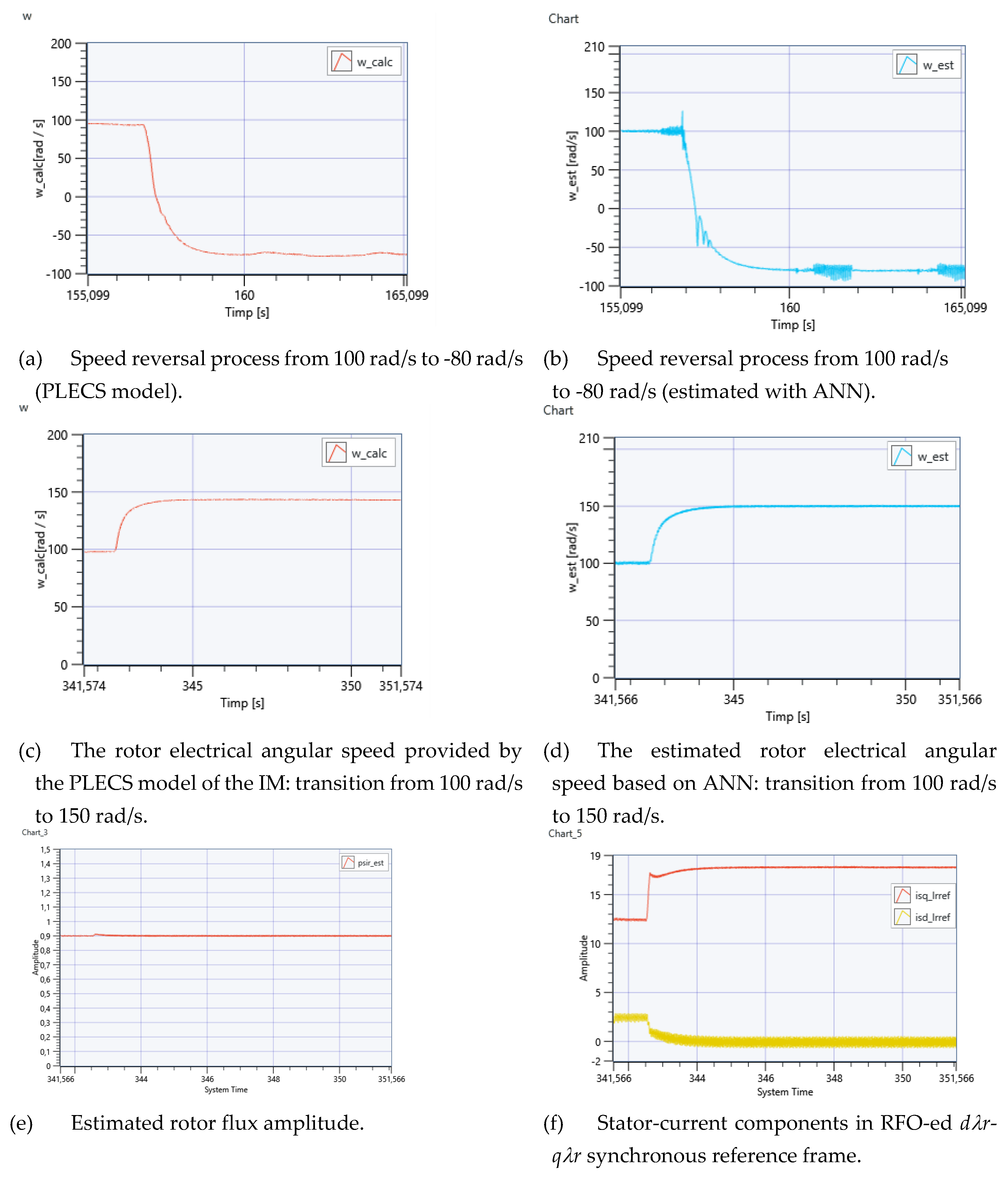
For the Rapid Control Prototyping (RCP) unit PXIe - 1071, the management software was NI VeriStand 2019 R3 and the modeling software was Matlab/Simulink (2018b). Within Matlab/Simulink, the vector control structure of the cage induction motor drive with dual field orientation embedded model was designed, tested, and the executable application program was generated for the NI PXIe-1071 and NI VeriStand infrastructure. The graphical dashboard implemented within NI VeriStand was used to adjust the Simulink Model parameters in real-time and to visualize the virtual waveforms produced by the analog outputs of the Real-Time target controller. To capture and visualize the results following the real-time simulation, graphical elements and tools from the NI VeriStand virtual instrumentation library were used. The real-time simulation for the sensorless vector control structure of IM with DFO was performed based on Hardware and Software setup. The speed was estimated based on ANN. The real-time simulation results are presented in Figure 13.
Figures 13 (a) and (b) are obtained for a speed reversal command from 100 rad/s to -80 rad/s, showing a good match between the results provided by the PLECS model and the ANN-based algorithm.
Figures 13 (c-f) present the speed transition from 100 rad/s to 150 rad/s, experiencing a smooth transition as seen in (c) and (d), where the estimated speed plot shows a better match with the set value than the one provided by the PLECS model. The rotor flux shown in Figure 13 (e) is not perturbed by this process, that demonstrates a good performance of the flux control loop. In Figure 13 (f) presents the evolution of the RFO-ed stator-current components during this transition. The magnetizing component is provided by the flux controller, while the torque producing one, the , by the speed controller, that presents a variation due to the speed dependent torque profile that was imposed.
4. Conclusions
This paper proposes an AI-based speed-sensorless vector control strategy for a cage-induction machine using dual-field orientation, validated by model-based simulation in Matlab/Simulink© environment and HIL simulation, based on PLECS RT BOX I and NI PXIe-1071 Real-Time target computer.
The classical RFO based control is replaced by DFOC to achieve parameter insensibility regarding the computation of the converter control variable, maintaining rotor-flux control for better performance and applying stator-field orientation to compute the reference voltage variable.
By the voltage computation process the two independent control loops are recoupled by means of the back e.m.f. (the electro-magnetic cross-effect) with a considerable impact on the controller tuning process. To reduce this impact a simplified structure is proposed that use only the flux and speed controllers and eliminate the two current controllers.
Speed-sensorless control structures for the induction motor have been successfully developed, including classical MRAS, as well as ANN- and RNN-based estimators, in accordance with the defined hardware and software configuration. Validation was performed covering a wide range speed profile, including speed reversal, applying a speed-dependent load-torque profile. The results demonstrate the accuracy of the speed estimation procedures, with the model’s predictions closely matching the reference values, especially for the RNN.
To further enhance performance, in the future an online RNN-based speed estimator may be adopted. Online training enables the RNN to continuously adapt to variations in system dynamics, external disturbances, noise measurement, and unmodeled nonlinearities such as load changes or thermal effects. This approach allows the model to become increasingly specialized to the real system during operation, eliminating the need for a comprehensive pre-collected dataset prior to deployment.
Additionally, the speed controller can be also replaced with AI-based regulators to improve the drive performance in a wide speed range.
Author Contributions
For research articles with several authors, a short paragraph specifying their individual contributions must be provided. The following statements should be used “Conceptualization, E.Sz. and Cs.Sz.; methodology, E.Sz. and Cs.Sz.; software, E.Sz. and L.-N.P.; validation, E.Sz., Cs.Sz. and L.-N.P.; investigation, E.Sz., Cs.Sz. and L.-N.P.; writing—original draft preparation, E.Sz. and Cs.Sz.; writing—review and editing, E.Sz. and Cs.Sz; visualization, E.Sz. and Cs.Sz.; supervision, E.Sz.; project administration, E.Sz. All authors have read and agreed to the published version of the manuscript.
Funding
This research received no external funding.
Institutional Review Board Statement
Not applicable.
Informed Consent Statement
Not applicable.
Data Availability Statement
The raw data supporting the conclusions of this article will be made available by the authors by request.
Acknowledgments
This work was supported by a grant funded by the National Grant Competition - GNaC ARUT 2023, Grant No. 19/01.07.2024.
Conflicts of Interest
The authors declare no conflicts of interest
References
- Wang, F.; Zhang, Z.; Mei, X.; Rodríguez, J.; Kennel, R. Advanced Control Strategies of Induction Machine: Field Oriented Control, Direct Torque Control and Model Predictive Control. Energies 2018, 11, 120. [Google Scholar] [CrossRef]
- Mon-Nzongo, D.L.; Jin, T.; Ekemb, G.; Bitjoka, L. Decoupling Network of Field-Oriented Control in Variable-Frequency Drives. IEEE Trans. Ind. Electron. 2017, 64, 5746–5750. [Google Scholar] [CrossRef]
- Reddy, B.; Poddar, G.; Muni, B.P. Parameter Estimation and Online Adaptation of Rotor Time Constant for Induction Motor Drive. IEEE Trans. on Ind. Applicat. 2022, 58, 1416–1428. [Google Scholar] [CrossRef]
- Zhao, F.; Zhang, J.; Wu, D.; Liu, G.; Lang, W.; Wang, P. The Effects of Parameter Variations on the Torque Control of Induction Motor. In Proceedings of the 2020 4th CAA International Conference on Vehicular Control and Intelligence (CVCI); IEEE: Hangzhou, China, December 18, 2020; pp. 757–760. [Google Scholar]
- Tang, J.; Yang, Y.; Blaabjerg, F.; Chen, J.; Diao, L.; Liu, Z. Parameter Identification of Inverter-Fed Induction Motors: A Review. Energies 2018, 11, 2194. [Google Scholar] [CrossRef]
- Dynamic Simulations of Adaptive Design Approaches to Control the Speed of an Induction Machine Considering Parameter Uncertainties and External Perturbations Available online:. Available online: https://www.mdpi.com/1996-1073/11/9/2339 (accessed on 8 July 2025).
- Ding, C.-W.; Tung, P.-C. A New Approach to Field-Oriented Control That Substantially Improves the Efficiency of an Induction Motor with Speed Control. Applied Sciences 2025, 15, 4845. [Google Scholar] [CrossRef]
- Luo, Y.-C.; Huang, W.-A. Sensorless Rotor Field Direct Orientation Controlled Induction Motor Drive with Particle Swarm Optimization Algorithm Flux Observer. Journal of Low Frequency Noise, Vibration and Active Control 2019, 38, 692–705. [Google Scholar] [CrossRef]
- Szőke Benk, E.; Imecs, M.; Szabo, C.; Incze, I. Double Field Oriented Sensorless Control of Cage Induction Motor. 2015, 403–408. [Google Scholar] [CrossRef]
- Bonet-Jara, J.; Quijano-Lopez, A.; Morinigo-Sotelo, D.; Pons-Llinares, J. Sensorless Speed Estimation for the Diagnosis of Induction Motors via MCSA. Review and Commercial Devices Analysis. Sensors 2021, 21, 5037. [Google Scholar] [CrossRef] [PubMed]
- Elbarbary, Z.M.S.; Al-Harbi, O.K.; Al-Gahtani, S.F.; Irshad, S.M.; Abdelaziz, A.Y.; Mossa, M.A. Review of Speed Estimation Algorithms for Three- Phase Induction Motor. MethodsX 2024, 12, 102546. [Google Scholar] [CrossRef] [PubMed]
- Shyaa, S. Review-Sensorless Techniques for Stabilization Control of Induction Motor Drives. Kerbala Journal for Engineering Sciences 2024, 4. [Google Scholar] [CrossRef]
- Białoń, T.; Pasko, M.; Niestrój, R. Developing Induction Motor State Observers with Increased Robustness. Energies 2020, 13, 5487. [Google Scholar] [CrossRef]
- You, J.; Wu, W.; Wang, Y. An Adaptive Luenberger Observer for Speed-Sensorless Estimation of Induction Machines. In Proceedings of the 2018 Annual American Control Conference (ACC); June 2018; pp. 307–312. [Google Scholar]
- Yildiz, R.; Barut, M.; Demir, R. Extended Kalman Filter Based Estimations for Improving Speed-Sensored Control Performance of Induction Motors. IET Electric Power Applications 2020, 14, 2471–2479. [Google Scholar] [CrossRef]
- Miloud, I.; Cauet, S.; Etien, E.; Salameh, J.P.; Ungerer, A. Real-Time Speed Estimation for an Induction Motor: An Automated Tuning of an Extended Kalman Filter Using Voltage–Current Sensors. Sensors 2024, 24, 1744. [Google Scholar] [CrossRef] [PubMed]
- Mansouri, S.A.; Ahmarinejad, A.; Javadi, M.S.; Heidari, R.; Catalão, J.P.S. Improved Double-Surface Sliding Mode Observer for Flux and Speed Estimation of Induction Motors. IET Electric Power Applications 2020, 14, 1002–1010. [Google Scholar] [CrossRef]
- Khan, U.; Sami, I.; Salman, K.; Khan, B.; Mehmood, C.A.; ALI, S.M. Sliding Mode Based Speed Observer Design for Speed Control of Five Phase Induction Motor. In Proceedings of the 2019 International Conference on Robotics and Automation in Industry (ICRAI); October 2019; pp. 1–6. [Google Scholar]
- Hamdi, W.; Hammoudi, M.Y.; Betka, A. Sensorless Speed Control of Induction Motor Using Model Reference Adaptive System and Deadbeat Regulator. Engineering Proceedings 2023, 56, 16. [Google Scholar] [CrossRef]
- Karlovský, P.; Lettl, J. Application of MRAS Algorithm to Replace the Speed Sensor in Induction Motor Drive System. Procedia Engineering 2017, 192, 421–426. [Google Scholar] [CrossRef]
- Damkhi, S.; Said, M.S.N.; Said, N.N. Speed Estimation of Induction Motor at Low and Zero Speed Using High Frequency Signal Injection for Rotor Slot Harmonics Detection. RE&PQJ 2018, 16. [Google Scholar] [CrossRef]
- Laadjal, K.; Bento, F.; Antunes, H.R.P.; Sahraoui, M.; Cardoso, A.J.M. Speed Estimation of Six-Phase Induction Motors, Using the Rotor Slot Harmonics. Sensors 2022, 22, 8157. [Google Scholar] [CrossRef] [PubMed]
- Diarra, M.N.; Zhao, X.; Wu, X.; Nketsiah, I.A.; Li, Y.; Zhao, H. Induction Motors Speed Estimation by Rotor Slot Harmonics Frequency Using Zoom Improved Chirp-Z Transform Algorithm. Energies 2022, 15, 7877. [Google Scholar] [CrossRef]
- Golsorkhi, M.S.; Binandeh, H.; Savaghebi, M. Online Efficiency Optimization and Speed Sensorless Control of Single-Phase Induction Motors. Applied Sciences 2021, 11, 8863. [Google Scholar] [CrossRef]
- Diab, A.A.Z.; Elsawy, M.A.; Denis, K.A.; Alkhalaf, S.; Ali, Z.M. Artificial Neural Based Speed and Flux Estimators for Induction Machine Drives with Matlab/Simulink. Mathematics 2022, 10, 1348. [Google Scholar] [CrossRef]
- Ramdani, D.R. Sensorless Speed Estimation of Induction Motor Using ANFIS. Journal of Information Systems Engineering and Management 2025, 10, 557–571. [Google Scholar] [CrossRef]
- Lai, Y.-S. Machine Modeling and Universal Controller for Vector-Controlled Induction Motor Drives. IEEE Transactions on Energy Conversion 2003, 18, 23–32. [Google Scholar] [CrossRef]
- Ahire, H.; Karuppasamy, I. Sensor-Less Speed Estimation Using Improved Stator Current Model Reference Adaptive System for Induction Motor. In Proceedings of the 2023 IEEE 20th India Council International Conference (INDICON); December 2023; pp. 572–577. [Google Scholar]
- Fan, B.; Yang, Z.-X.; Wang, X.-B.; Song, L.; Song, S.-Z. Model Reference Adaptive Vector Control for Induction Motor without Speed Sensor. Advances in Mechanical Engineering 2017, 9, 1687814016683086. [Google Scholar] [CrossRef]
- Zorgani, Y.A.; Jouili, M.; Koubaa, Y.; Boussak, M. A Very-Low-Speed Sensorless Control Induction Motor Drive with Online Rotor Resistance Tuning by Using MRAS Scheme. Power Electronics and Drives 2019, 4, 125–140. [Google Scholar] [CrossRef]
- Norambuena, M.; Galvez, D. Model Free Artificial Neural Network for an Induction Machine. In Proceedings of the 2023 IEEE Conference on Power Electronics and Renewable Energy (CPERE); IEEE: Luxor, Egypt, February 19, 2023; pp. 1–6. [Google Scholar]
- Elgohary, M.; Gouda, E.; Eskander, S.S. Intelligent Control of Induction Motor without Speed Sensor. IJPEDS 2021, 12, 715. [Google Scholar] [CrossRef]
- Purwahyudi, B. RNN Based Rotor Flux and Speed Estimation of Induction Motor. International Journal of Power Electronics and Drive Systems (IJPEDS) 2011, 1, 58–64. [Google Scholar] [CrossRef]
- Marinov, E.Y.; Zhekov, Z.S. Neural Sensorless Control of Induction Motor. In Proceedings of the Second International Scientific Conference “Intelligent Information Technologies for Industry” (IITI’17); Abraham, A., Kovalev, S., Tarassov, V., Snasel, V., Vasileva, M., Sukhanov, A., Eds.; Advances in Intelligent Systems and Computing; Springer International Publishing: Cham, 2018; Vol. 679, pp. 411–418, ISBN 978-3-319-68320-1. [Google Scholar]
- Merabet, A.; Kanukollu, S.; Al-Durra, A.; El-Saadany, E.F. Adaptive Recurrent Neural Network for Uncertainties Estimation in Feedback Control System. Journal of Automation and Intelligence 2023, 2, 119–129. [Google Scholar] [CrossRef]
- Pintilie, L.-N.; Teodosescu, P.-D.; Hedeșiu, H.-C.; Gros, I.-C.; Suciu, V.-M.; Iuoraş, A.-M. Real-Time Hardware in the Loop Simulation Setup for Automotive Grid Interfacing System Based on PLECS RT BOX and National Instruments PXI. In Proceedings of the 2024 IEEE International Conference on Electrical Systems for Aircraft, Railway, Ship Propulsion and Road Vehicles & International Transportation Electrification Conference (ESARS-ITEC), November 2024; pp. 1–7. [Google Scholar]
- RT Box 1 | Plexim Available online:. Available online: https://www.plexim.com/products/rt_box/rt_box_1 (accessed on 30 June 2025).
- PXIe-1071 Specifications - NI Available online:. Available online: https://www.ni.com/docs (accessed on 30 June 2025).
Figure 1.
Speed-sensorless vector control structure of a VSI-fed induction motor with DFO.
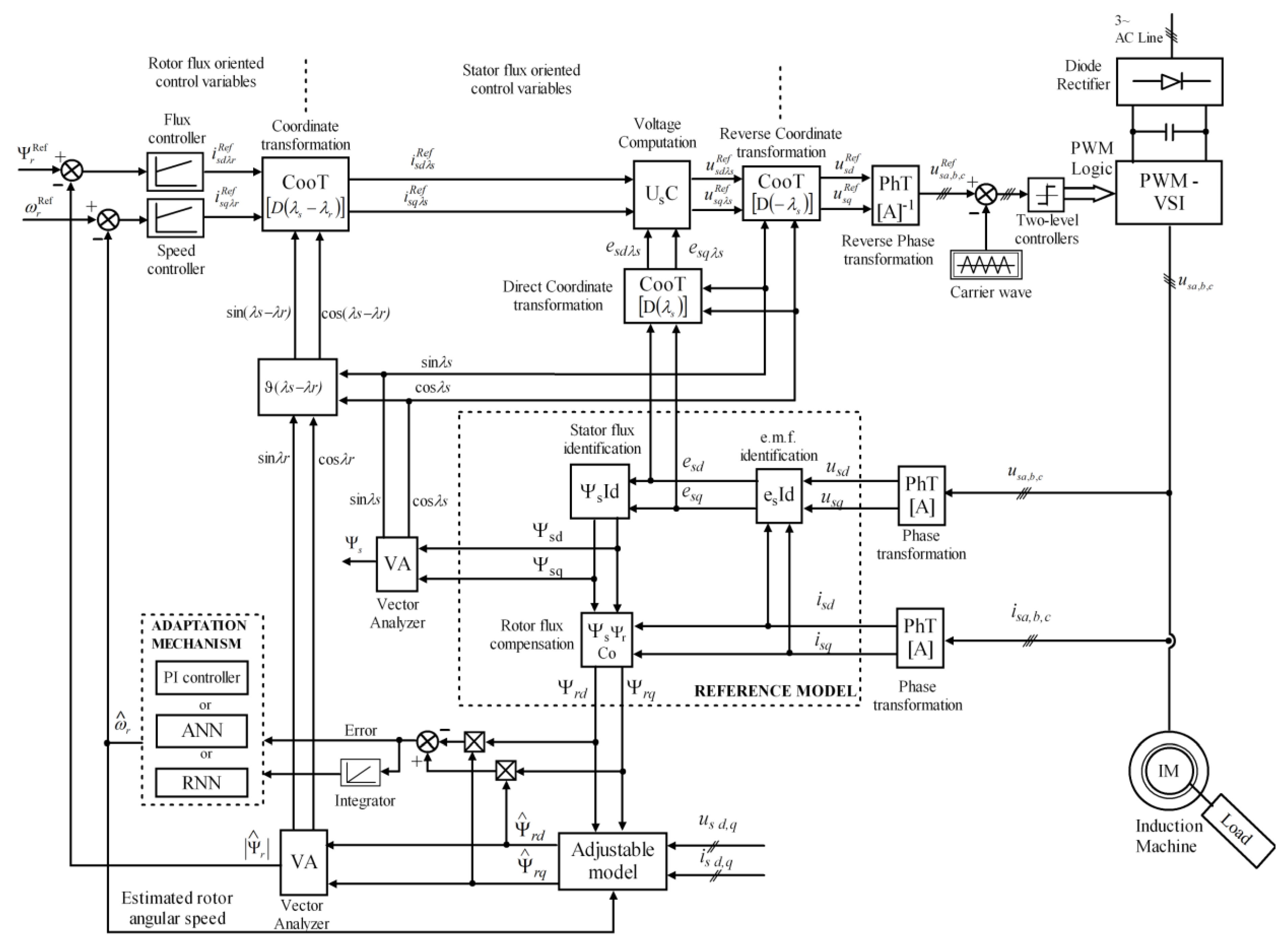
Figure 2.
The flowchart of the speed sensorless procedure.
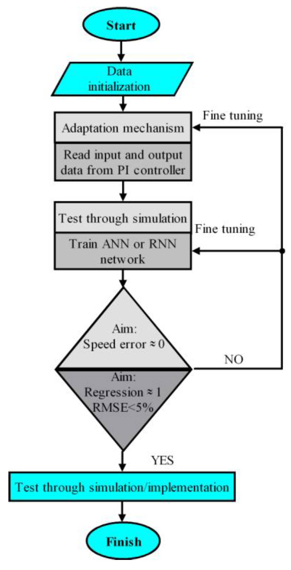
Figure 3.
Figure 3. The MRAS model for speed estimation.
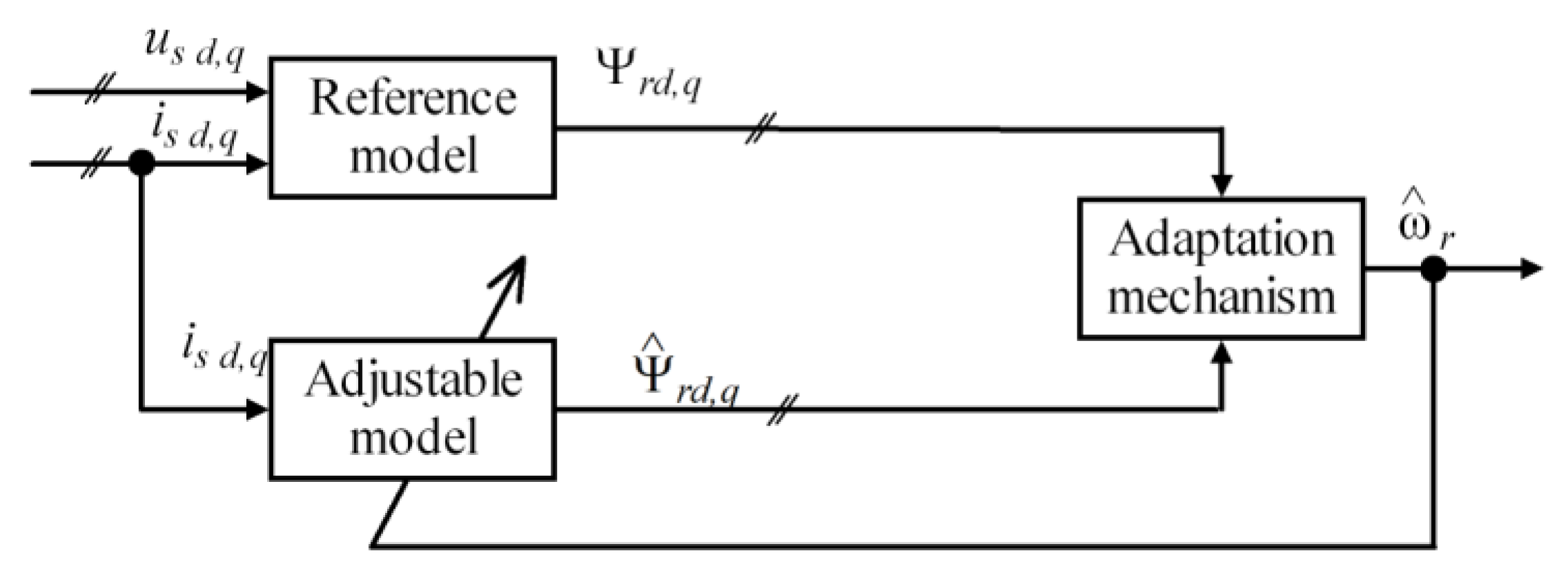
Figure 4.
Simulation results for MRAS procedure.
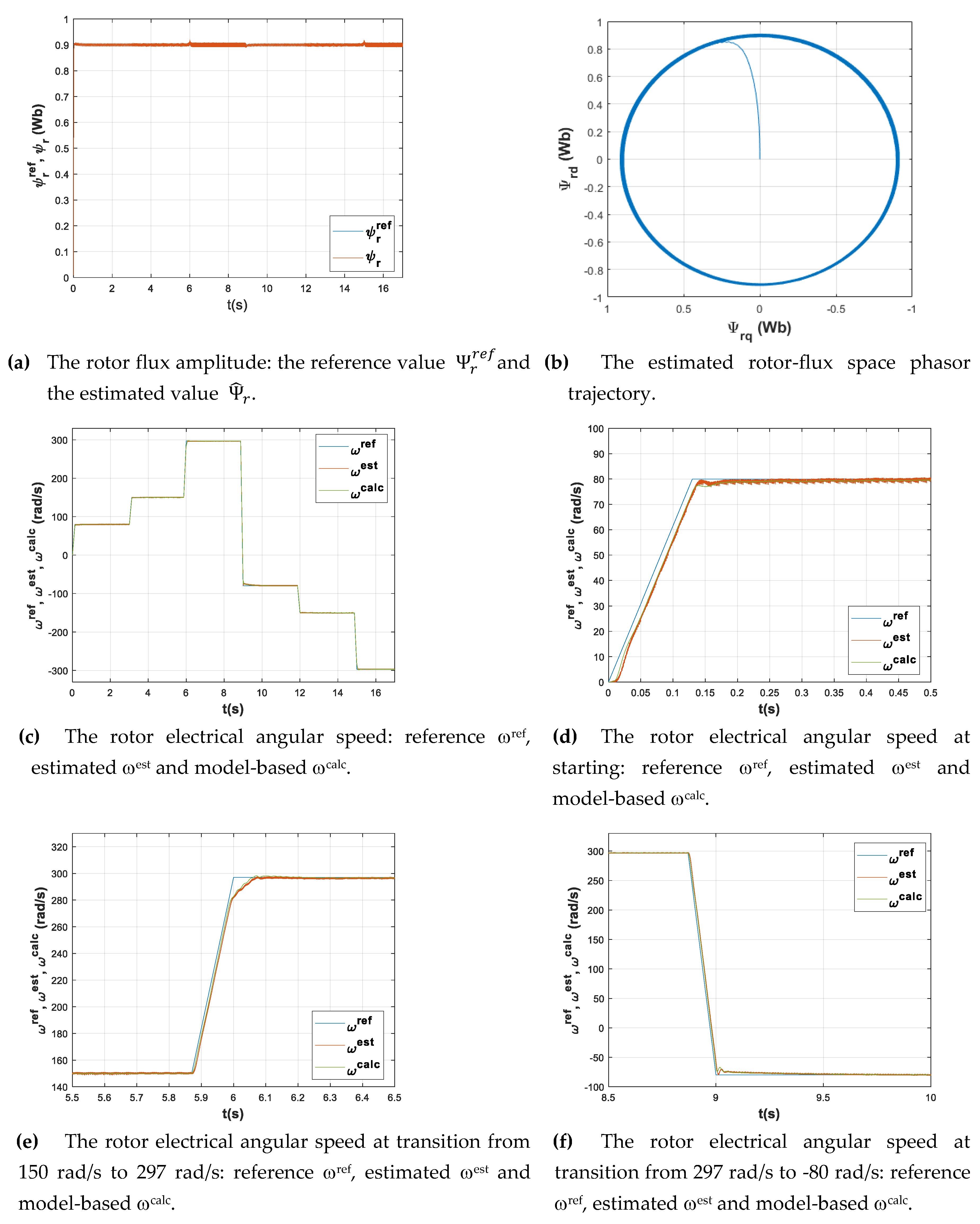
Figure 5.
The structure of the ANN.
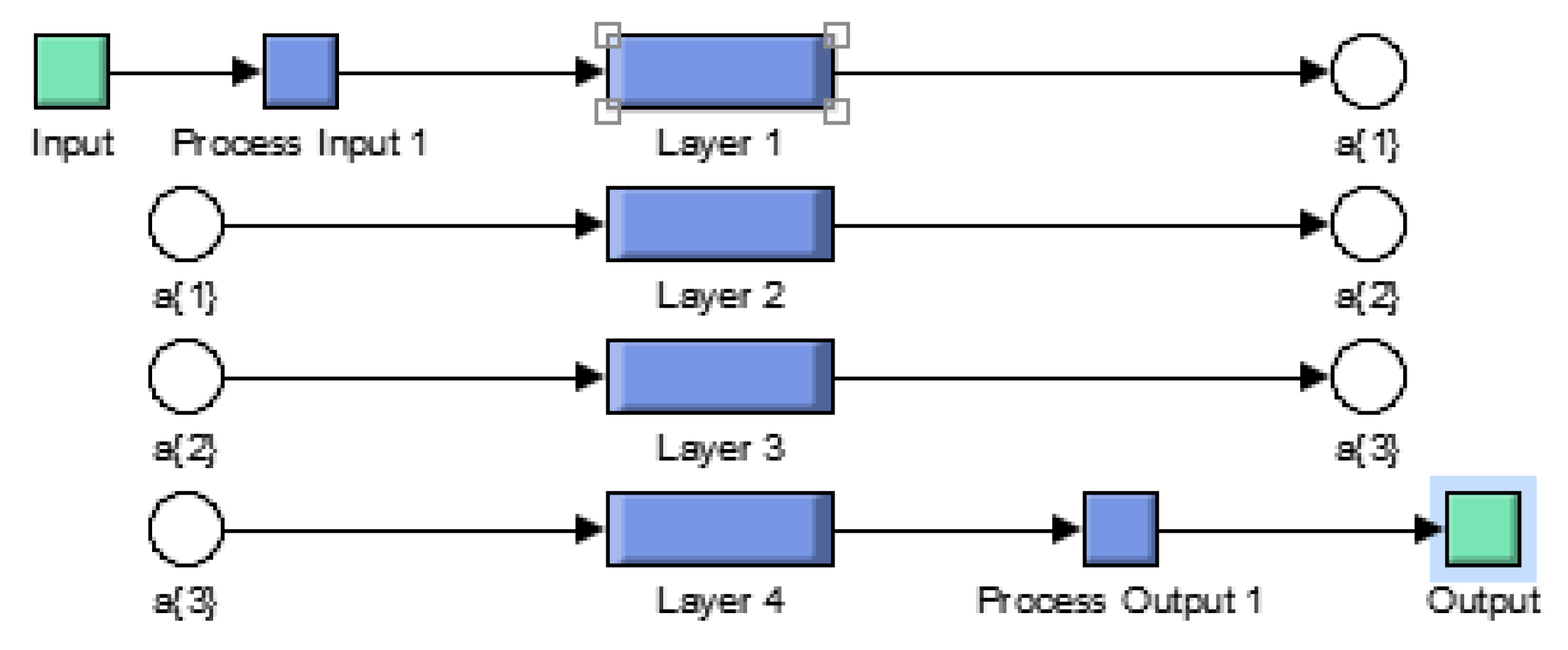
Figure 6.
The ANN training tool interface.
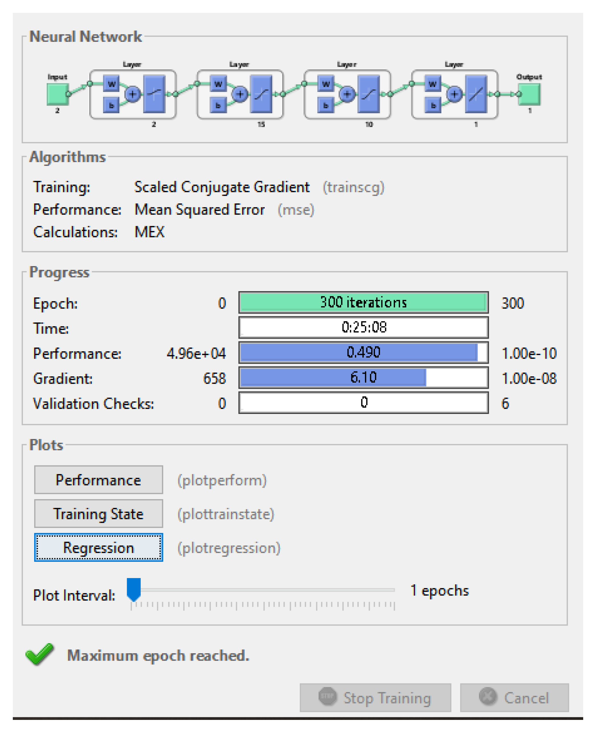
Figure 7.
(a) The training performance; (b) The regression plot.
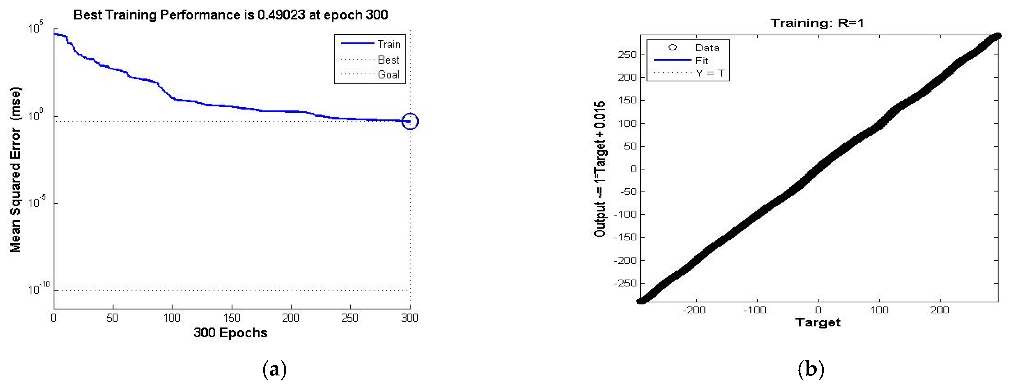
Figure 8.
Simulation results for ANN procedure.
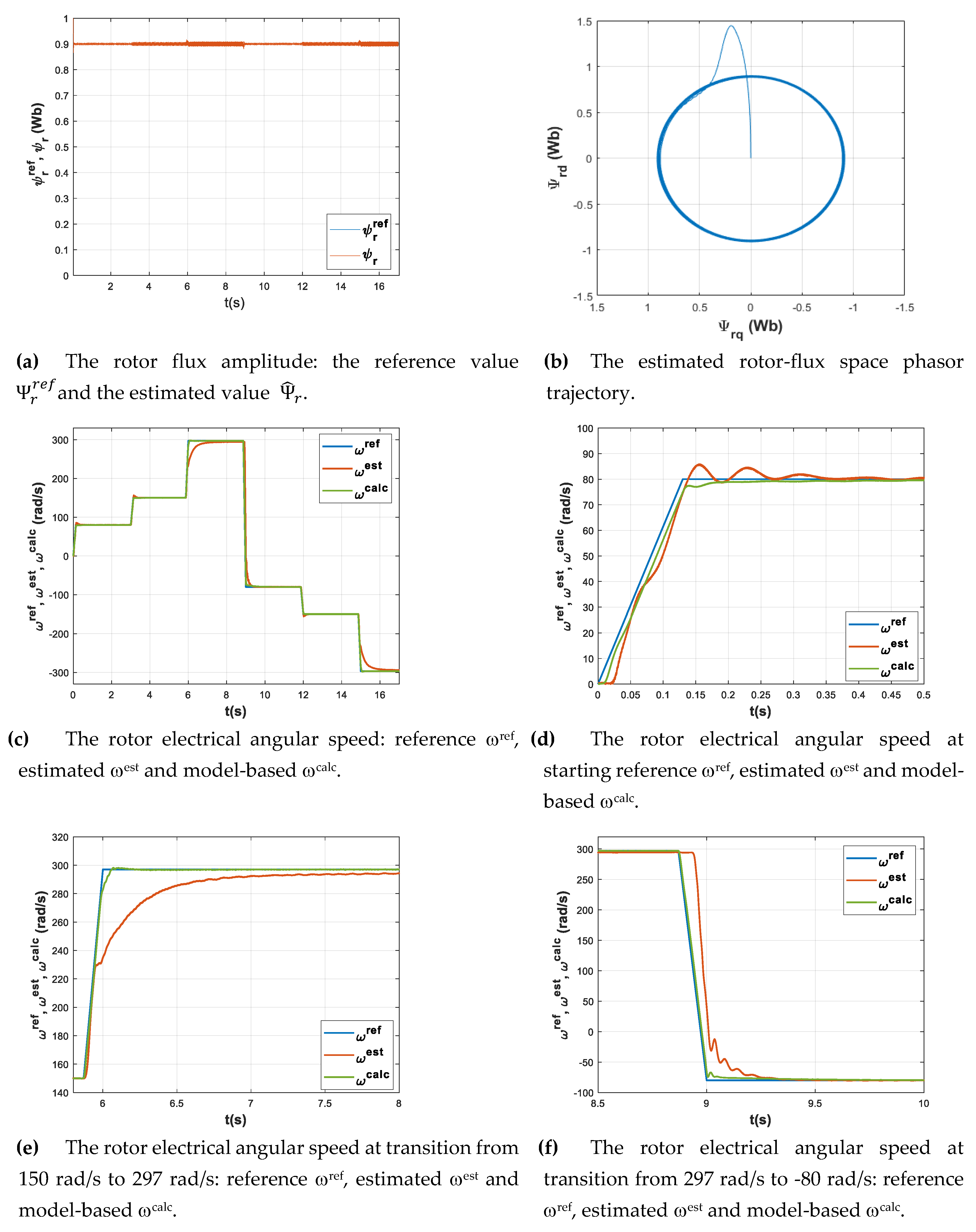
Figure 9.
The RNN training tool interface.
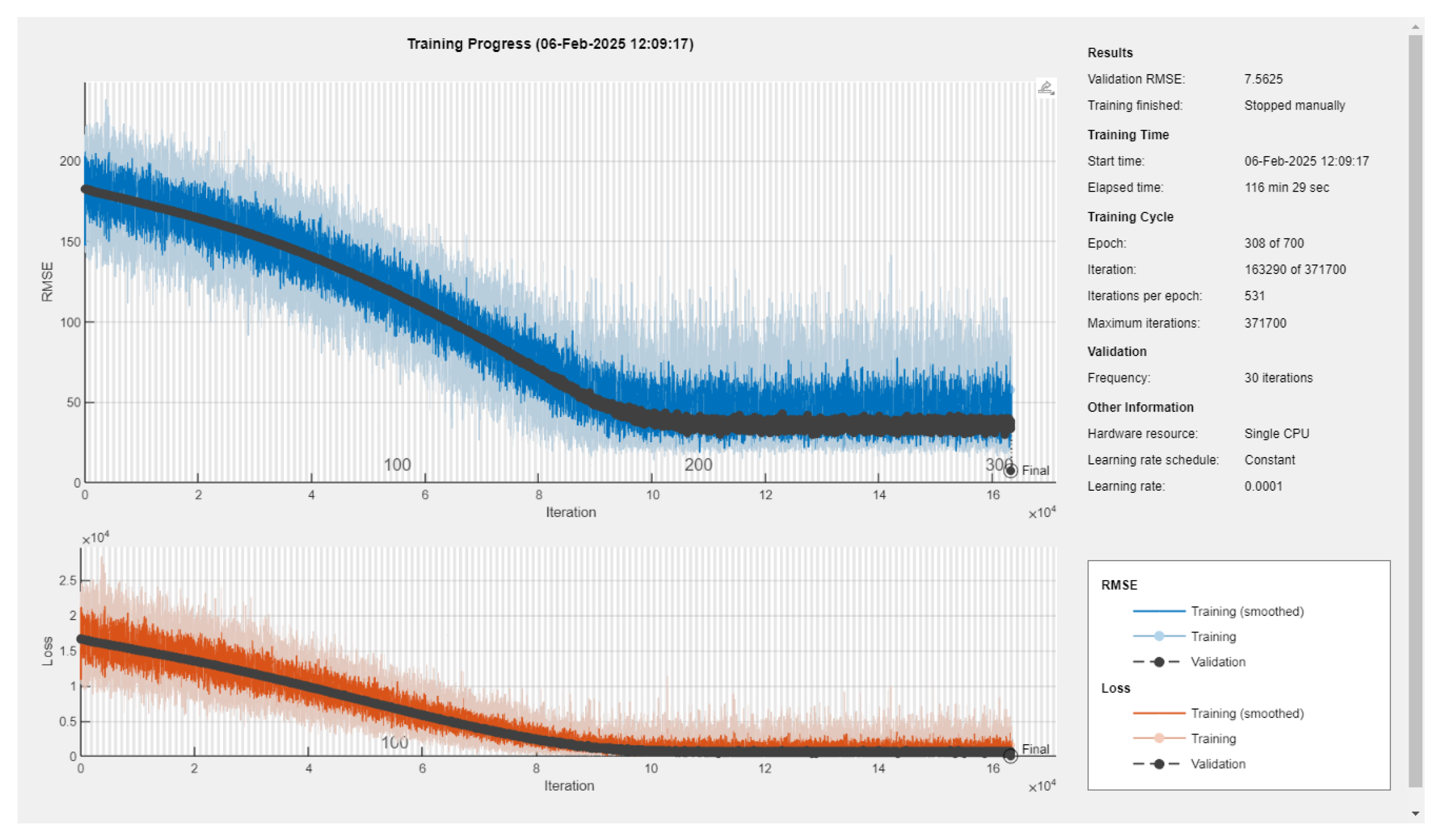
Figure 10.
Simulation results for RNN procedure.
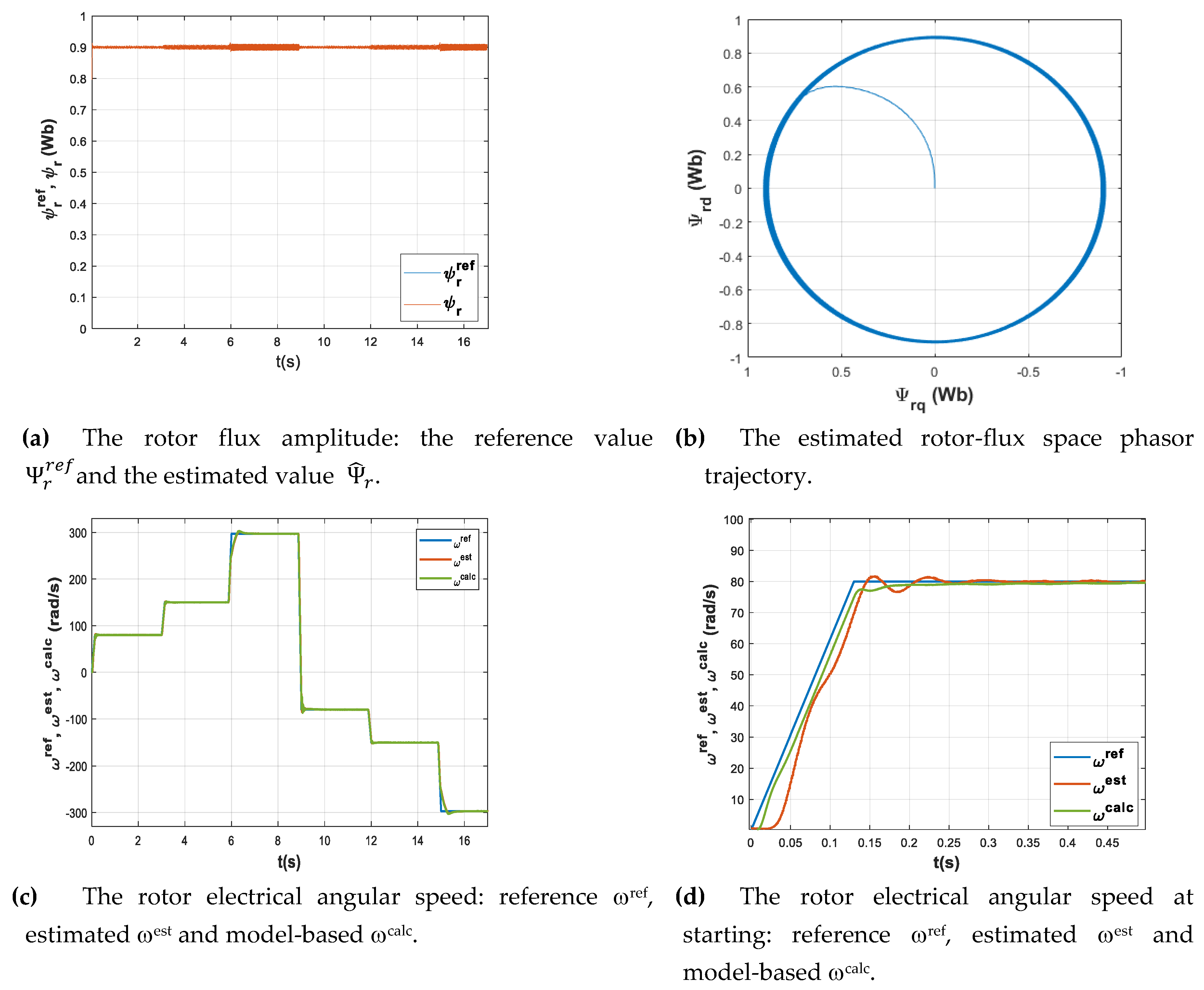
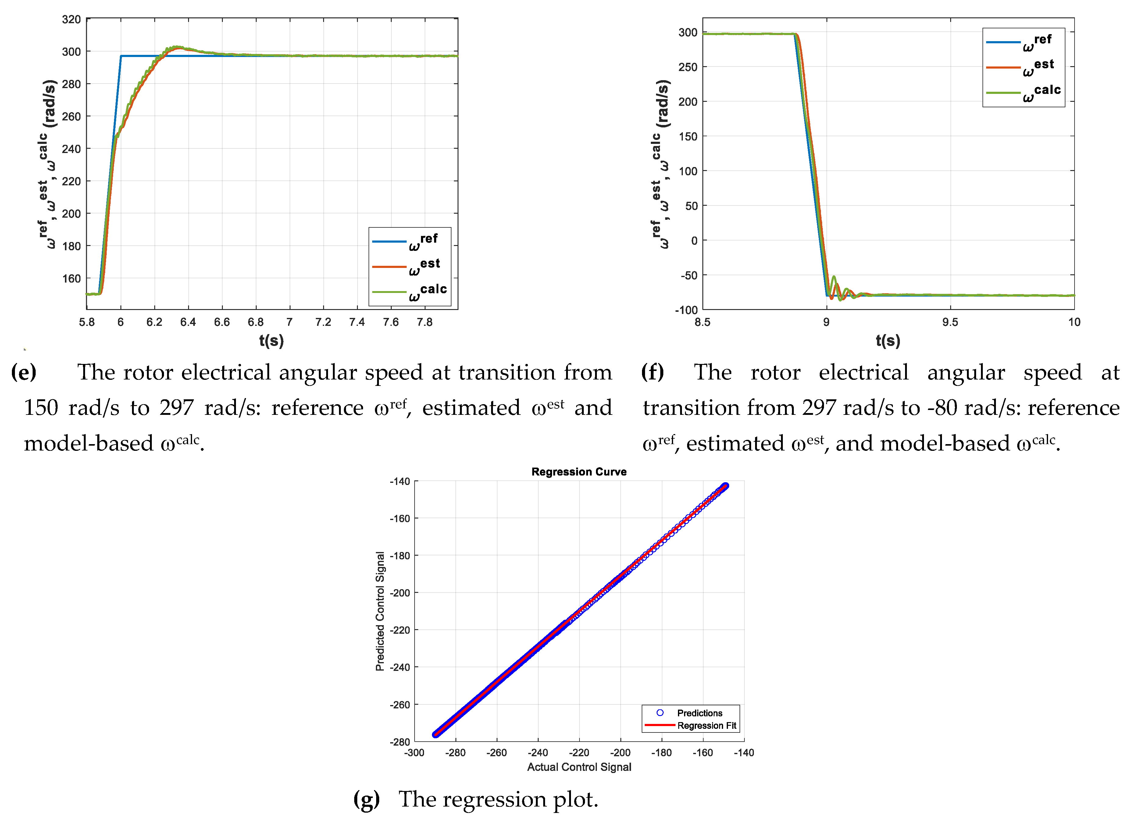
Figure 11.
The HIL implementation.
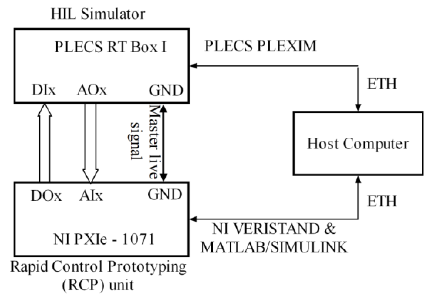
Figure 12.
The hardware setup.
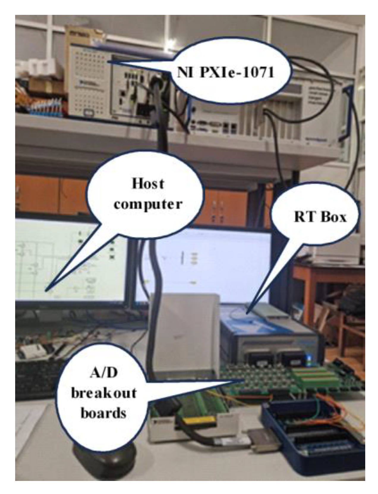
Figure 13.
Real-time simulation results.
Disclaimer/Publisher’s Note: The statements, opinions and data contained in all publications are solely those of the individual author(s) and contributor(s) and not of MDPI and/or the editor(s). MDPI and/or the editor(s) disclaim responsibility for any injury to people or property resulting from any ideas, methods, instructions or products referred to in the content. |
© 2025 by the authors. Licensee MDPI, Basel, Switzerland. This article is an open access article distributed under the terms and conditions of the Creative Commons Attribution (CC BY) license (http://creativecommons.org/licenses/by/4.0/).
Copyright: This open access article is published under a Creative Commons CC BY 4.0 license, which permit the free download, distribution, and reuse, provided that the author and preprint are cited in any reuse.


