Submitted:
26 May 2025
Posted:
27 May 2025
You are already at the latest version
Abstract
The use of an adaptive Neuro-fuzzy inference system (ANFIS) for speed estimation of an induction motor is presented in this paper. The ANFIS (neuro-fuzzy inference adaptive system) speed observer was created in response to the limitations of mechanical sensors. It is based on an artificial intelligence technique that combines the ideas of fuzzy inference systems and neuron networks. Since there is no need for a speed sensor, the ANFIS rotor speed estimator is simple to use in practice and relies only on readily available, measurable stator quantities (voltages and currents). This lowers costs. Furthermore, the vector controlled induction motor with stator field orientation (SFO) is also covered in this work. It is commonly known that the vector control approach relies on the concurrent calculation of the flux vector's magnitude and argument. By providing decoupling between an induction motor's torque and flux, this control method effectively addresses the intricate control challenge of these machines. On the other hand the multilevel inverter has been proposed as an alternative solution for applications involving high power and medium voltage. This paper presents also specifically the NPC topology and outlines the most known control technique SVM technology space vector modulation.
Keywords:
induction motor (IM)
; ISFOC
; three-level NPC inverter
; SVM
; ANFIS
1. Introduction
Induction motors are among the most widely used electrical machines in mechanical motion control systems and household appliances. Their simple and robust design, low power consumption, negligible maintenance, and coordinated association with AC drive make them a preferred choice in other fields such as aviation, petrochemical, and medicine. However, their control has been limited by the complexity of the nonlinear coupling between flux and torque, which makes their performance more challenging than that of DC motors.
Despite this complexity, advances in control devices and control methods have greatly expanded the use of induction motors in industrial applications. One of the most compelling control approaches is flux vector control, presented by Blaschke in 1972 [15,16,17]. This method allows precise control of torque and speed by decoupling the flux and torque components, allowing induction motors to provide performance comparable to DC motors in demanding applications.
On the other hand, an idle converter that transforms a DC indicator into an AC indicator is called an inverter. Most often, the input DC power of the inverter, determined from a rectifier, can also be supplied by a battery. Changing the input and output connections on a normal basis produces the output indicator of the exchange. The output indicator of an inverter includes a variable frequency control. The applications of an inverter are diverse and include control instruments, railway transport systems, electric cars, and mechanical gears for outboard motors.
Multilevel inverters, particularly the three-level neutral-point-clamped (NPC) inverter, have become more popular among inverter topologies because of their capacity to generate high-quality output voltage with lower harmonic distortion [3,4,5,6].The most popular multilevel topology is the diode clamped inverter topology, which uses a diode as a clamping device to clamp the dc bus voltage and produce output voltage steps. Nabae, Takahashi, and Akagi created the first topology model in 1981 [18], which was essentially a three-level diode-clamped inverter. The common dc bus that exists on phases reduces the need for capacitors, which is one of the topology's advantages.
Because of this, the topology is not only feasible but also useful for applications like an adjustable speed drive or a high voltage connection. Secondly, it is possible to pre-charge the capacitors collectively. Furthermore, fundamental frequency switching has a high efficiency, and when the number of levels is high enough, harmonic content will be low, allowing filters to be removed.
In a motor drive, an inverter produces a variable output voltage for the motor. The inverter's output performance is determined by its control. The literature contains a variety of techniques for managing the inverter switches. Among these strategies are the SVM technique and standard PWM pulse width modulation. Recently, there has been a lot of interest in studying the SVM approach [6].
In addition to this Multi-level inverters use Space Vector Modulation (SVM), a sophisticated pulse width modulation (PWM) technique, to minimize harmonic distortion and maximize voltage utilization. SVM effectively synthesizes the desired output voltage by representing inverter switching states as vectors in a complex plane. High-performance motor drives frequently use this technique because it improves control accuracy and reduces switching losses [19,20,21].
Until now, the estimation of speed is based on the method of generated information. This method consists either of using fuzzy logic, or of the organization of neurons, or of combining both (example of an ANFIS estimator). The latter method is cost-effective because it allows us to take advantage of fuzzy logic and the preferences of the organization of neurons. At the same time, the emergence of more efficient processors has made possible the use of new advanced control laws such as vector control, ... These electronic devices have thus been able to discover, with the DC motor, the flexibility and control of electromagnetic commutation, obtained with the DC motor. In addition, if the motor is used in unfavorable conditions, the sensitivity of mechanical sensors will be degraded. It therefore remains imperative that sensorless control machines are, in recent years, the most important interface of research centers and schools in mechanics. Several hypotheses have been proposed to evaluate the speed from the available quantities (stator currents and voltages). Indeed, to overcome the drawbacks of mechanical sensors and to unravel the problem of transformation of stuck points, we use perception calculations called too virtual sensors. Several approaches of sensorless control of the induction machine are developed in writing. They can be classified into two main approaches. The first approach is not based on the demonstration model. The second approach is based on the demonstration model of the machine modeling its behavior. It is based on procedures from automated perception. There are several estimation methods such as the Kalman channel and its derivatives, the Luenberger model and its derivatives [26], versatile methods such as the versatile reference model estimation method [25,26,27,28,29], models based on fabricated information (neural organization, fuzzy logic, etc.). Currently, sensorless control is based on the artificial information procedure using either fuzzy logic or neural organization or combining both (ANIFS estimator) [22,23,24,27,28]. The latter is more effective because it allows us to appreciate the strengths of both.
In this paper, to avoid the drawbacks of the harmonics caused by the classical pulse modulation approaches in two levels inverter, the used three phase induction motor is fed with a three levels NPC inverter managed with a Space Vector Modulation. An estimation algorithm based on the ANFIS approach is used to avoid the drawbacs of the mechanical sensor. To ensure independence control of the torque and the field in the induction motor, a stator flux orientation control (ISFOC) approach is investigated.
The outline of this paper is organized as follows: Section II presents the mathematical model of the induction motor. Section III discusses the ISFOC control strategy, while Section IV presents the speed estimator design ANFIS. Section V details the three-level NPC inverter design and finally simulation results are provided in Section VI, followed by conclusions in Section VII.
2. Induction Motor
We must first go through a foundational level called modeling in order to reach the simulation and realization phases. At this stage, we should choose a model that will allow us to correctly understand every phenomenon the system designer wants to highlight and guarantee that the behavior of the system will be predicted under both dynamic and static situations.
The induction motor adopted is here below:
Where
The transformation of variables from (a, b, c) to (d, q) is given by this matrix (Park transformation)

Table 1.
Induction Motor Parameters.
| Parameter | Design |
|---|---|
| Vds and Vqs | d-q axis stator voltages respectively |
| Ids, Iqs, Idr, and Iqr | d-q axis stator currents d-q axis rotor currents respectively |
| Rs, Rr | Stator and rotor resistance per phase respectively |
| p | Number of poles |
| ωs, ω | Speed of the rotating magnetic field and the rotor speed respectively |
| Ce | Electromagnetic developed torque. |
| Ls, Lr, M | Self-inductances of the stator and rotor and the mutual inductance respectively |
3. ISFOC Vector Control by Stator Flux Orientation
In order to control the vector of an asynchronous machine using stator flux orientation, the reference frame (d, q) must be aligned with the stator flux that requires orientation on the d axis. Since stator currents are easily observable, simply the torque equations pertaining to them are used to control the induction machine's torque and speed. Key reference factors are the slip speed and the direct stator flux [7].
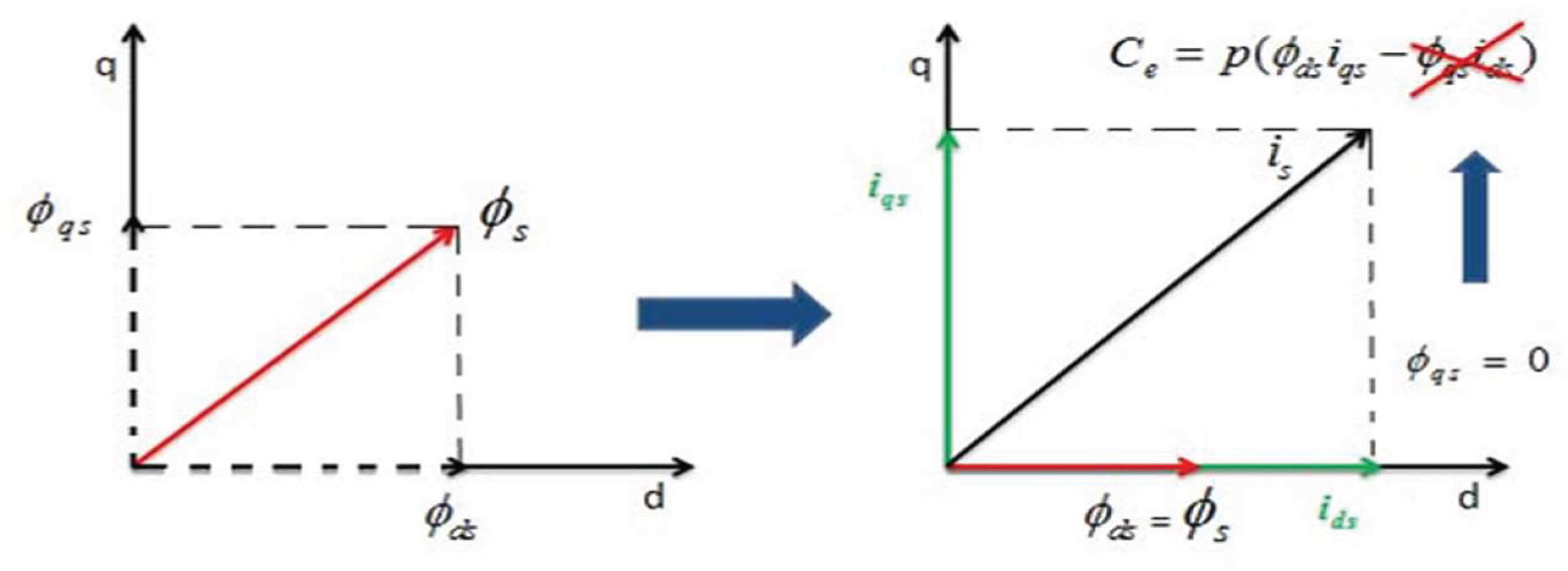
Figure 1.
ISFOC Philosophy [7].
Figure 1.
ISFOC Philosophy [7].
4. Speed Estimation
4.1. ANFIS Algorithm
Takagi Sugeno fuzzy inference is used by hybrid systems called Adaptive Neuro-Fuzzy Inference Systems (ANFIS). The graphic of Figure 2. illustrates the five levels that make up the ANFIS structure. The gradient (back propagation) algorithm optimises the parameters of the premise sections throughout his training, and the least squares algorithm solves parameter finding parts to lower the error. To make comprehension easier, we look at a system that has one output (y) and two inputs (x1 and x2), represented by a fuzzy system type TSK (Takagi-Sugeno-Kang) made up of two rules [30]:
if x1 is A1 and x2 is B1 then y1 = f1(x1, x2) = a1x1 + b1x2+ c1
if x1 is A2 and x2 is B2 then y2 = f1(x1, x2) = a2x1 + b2 x2 + c2
The adaptive network ANFIS is a multi-layer network whose connections are not weighted. The nodes are of two different types according to their functionalities: square nodes (adaptive) contain parameters, and circular nodes (fixed) do not have parameters. In another hand, each element of layer : circular or square called node where a function is applied on its input signals. As shown on Figure 2, the nodes of the same layer have functions from the same family that we explain below. The layer k has a node i which has an output O (i, k), so any node is n (i, k) and uses layer (k-1) signals. Node (i, k) parameters are :
O (i, k) = f (O (1, k-1)…O (nK-1, k-1), a, b, c …).
Where nK-1 is layer (k-1) nodes number, and a, b, c… are its parameters. Concerning the circular node, these parameters do not exist.
- Layer 1: Generation of the membership degree:
Here each node has adjustable parameters. Node function is identical to the membership function of a fuzzy subset of the universe of discourse of the inputs.
O(i, l) = f(i, l) (x) = ȠAi(x)
x: node i input,
Ai & (ȠAi): associated linguistic term and its function.
O(i, l) : x membership degree in Ai that is defined by defined by ȠAi(x).
- Layer 2: Rule i generation weight:
The node named (pi) is a circular node and corresponds to a Sugeno fuzzy rule. It receives the outputs of the fuzzification nodes and calculates its activation. The conjunction of the antecedents is performed with the product operator.
Wi = ȠAi(x1).ȠBi-2(x2), i = 1…2
- Layer 3: Rule i normalization weight:
This layer presents circular node called N. A given fuzzy rule is used here to calculate the normalized activation degree. Obtained value shows fuzzy rule contribution that is obtained here and is a final result.
- Layer 4: Rules calculation output:
This layer shows a square node with a function using the following calculation:
vi : layer 3 output , and {ai, bi, ci} is the set of adjustable output parameters of rule i.
O(i, 4) = vi.f = vi (aix1 + bix2+ ci)
- Layer 5: ANFIS calculation by sum generation:
It generates the output of ANFIS by summing the outputs of all defuzzification nodes.
4.2. ANFIS Speed Estimator
A novel method for induction motor speed control without sensors is introduced. Instead of employing a mechanical sensor, the new method estimates rotor speed using an adaptive neural fuzzy inference system (ANFIS). The simulation is done using MATLAB software where ANFIS is obtained using the anfisedit command in the command window along with its hybrid learning algorithm based on back propagation and least squares method. This model gives very good results in approximating nonlinear functions.
The following are the ANFIS system operations in MATLAB:
1) It is necessary to select a group of membership functions.
2) The input-output data that ANFIS will use and that is meant for training.
Because the speed estimation solely relies on the quantifiable stator quantities (stator currents and voltages), they are added as ANFIS block inputs. It should be noted that if the system is adequately represented in the learning base level modeling, the system will produce good outcomes. The following Table 2. presents parameters of suggested ANFIS and Figure 3 presents characteristics of proposed ANFIS as design and surface viewer:
5. NPC Inverter
For multi-level inverters, whose applications are extremely varied and impact many branches of electrical engineering, power electronics development is crucial. The so-called "three-level" inverter has practically become a classic product, multi-level inverter technology is now a significant research subject, and new topologies have emerged recently at both the academic and industry levels. NPC inverter technology is mostly used in these topologies [3,4,6]. The most popular multi-level inverter topologies and their standard SVM control methods are shown below.
5.1. NPC Topology
NPC three-level inverters are well-liked in both academia and industry because of its appealing features, straightforward design, and control system. The NPC three-level inverter also has reduced output current ripple and common-mode voltage. We use surely the same switching frequency as a two-level inverter.
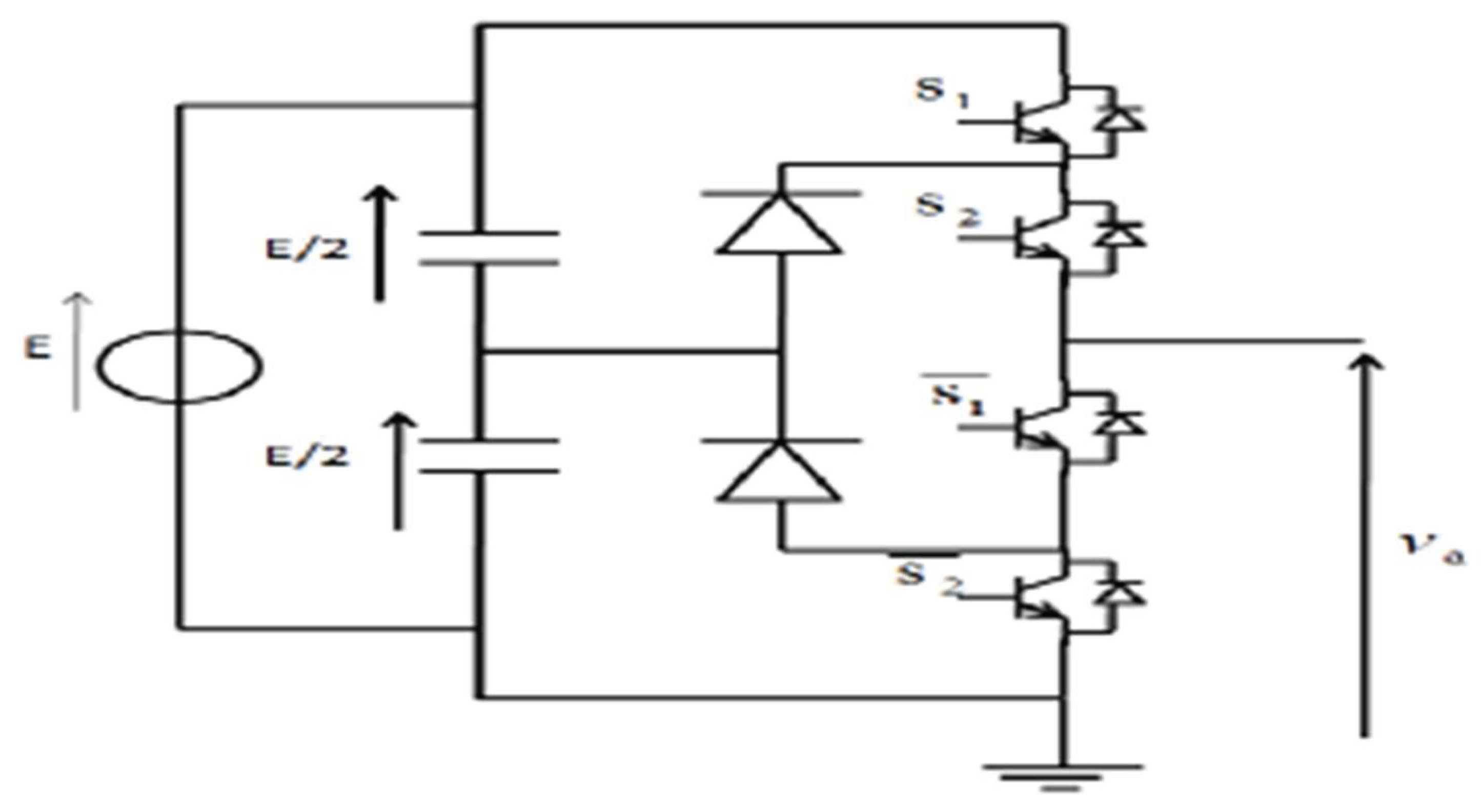
Figure 5.
Three level NPC inverter one leg.
5.2. SVM Topology
Three-level inverters can be controlled using the space vector modulation (SVM) technique. It offers a variable-width output signal. It is a control method that is readily adaptable to all multilevel inverters. The general characteristics of SVM as a method are low current ripple, efficient dc-link voltage utilization, and simplicity of implementation by a digital signal processor (DSP). These characteristics guarantee the ability to be appropriate for applications requiring high voltage power. The space vectors for the three-level inverters are displayed in Figure 6. Regardless of the kind of multilevel inverter, these vector diagrams are universal. By calculating the duty cycle for each of the three neighboring vectors (Vj, Vj+1, and Vj+2), a desired voltage vector can be synthesized.
A three-level NPC inverter with three-phase voltage, which one from three legs represented by Figure. 5, has twelve switching cells (four switching by leg). For each modulation period of the inverter, the two-phase voltages provided by the control algorithm can be expressed in a fixed frame by their projections Vsα and Vsβ. So we can make the control just of a two-phase vector. The transformation matrix is:
The different switching states of the three arms of the inverter, the voltages between the different points of a three-level inverter and the voltages in the (d,q) frame are presented in (Table 3).
6. Results and Discussion
Simulations to evaluate the performance of the estimator considering the vector drive system and the three-level NPC inverter were done from the Matlab/Simulink software.
Figure 7 shows the overall scheme used for simulation. The scheme includes an induction motor model, the three-level NPC inverter, ANFIS estimator and the ISFOC block. SVM control topology bloc is included into the three-level NPC inverter bloc.
Initially, the simulation is run at no load. Then, it is run under various operated speed condition that are : 200 rad/s then 314 rad/s and then is run on reverse engine direction (-100 rad/s) as it is shown on Figure 8, which presents clearly how real speed follows well the reference speed. Figure 8 shows the stator flux evolution. D-axis flux directly stabilizes at the desired value 0.9 Wb, while the q-axis flux is zero. So decoupling between torque and flux is ensured. So decoupling between torque and flux is ensured.
The simulation results illustrate that the proposed ANFIS design estimator presents good results (Figure 8), we note that the estimated speed follows the real speed, at various operated speed
The simulation results show that the suggested NPC three-level inverter design with an induction motor produces good performance. Furthermore, the results illustrate the impact of the SVM method on IM driving, as well as the possibility of combining the SVM three-level inverter with ISFOC control, shows the stator flux evolution. D-axis flux directly stabilizes, while the q-axis flux is zero. This confirms also the ISFOC, as IRFOC, is an effective method releasing the decoupling between torque and flux. Figure 10 shows the phase-neutral voltage of the three-phase three-level NPC inverter controlled by the SVM (Space Vector Modulation) technique, illustrating the three distinct voltage levels. Figure 11 shows the neutral-phase voltage of the three-phase three-level NPC inverter with SVM modulation, highlighting the different voltage levels accessible thanks to the multilevel topology. And, figure 12 shows the phase current at the output of the three-level NPC inverter feeding the asynchronous motor, controlled by the SVM technique;
To summarize, we note following points:
- RMS Error (Root Mean Square Error): The RMS error between the estimated and actual speed is 2.5 rad/s at 200 rad/s.
- Maximum Error: The maximum deviation observed during direction reversal is 5 rad/s.
- Response Time: The system reaches 95% of the reference speed in 0.2 seconds.
- Energy efficiency: The overall efficiency of the system is 92% at full load.
- Current/torque ripple: The stator current ripple is limited to 3% thanks to SVM modulation.
- Flux/torque decoupling (ISFOC): Quadrature (q-axis) flux amplitude: The q-axis flux is maintained at 0.02 Wb (±0.5%), confirming decoupling.
- ANFIS reduces the average error by 30% compared to a Luenberger observer or other observers’ techniques.
7. Conclusions
The proposed model in this work, presents an optimized implementation of ISFOC control of induction motor powered by a three-level NPC inverter using SVM. Compared to conventional approaches, that uses the IRFOC or another control system as DTC, ISFOC, our proposed method, enhances IM control by ensuring decoupling between flux and torque and by this bypassing the machine complexity control. Simulation results demonstrate also the benefice of three-level NPC inverter with SVM topology as the most known combination between inverter strategy and control topology, making this approach particularly suitable for asynchronous machine. Added to this we can say that the ANFIS estimator presents good results, so it is a good solution to replace speed sensors and just generate speed values from just measurable stator quantities (voltages and currents). By the way it shows the effective of artificial intelligence used technique combining fuzzy inference systems and neuron networks.
References
- SADHWANI, Rahul & RAGAVAN, K. A comparative study of speed control methods for induction motor fed by three level inverter. In: 2016 IEEE 1st International Conference on Power Electronics, Intelligent Control and Energy Systems (ICPEICES). IEEE, 2016. p. 1-6.
- NATHENAS, Thomas & ADAMIDIS, Georgios. A new approach for SVPWM of a three-level inverter-induction motor fed-neutral point balancing algorithm. Simulation Modeling Practice and Theory, 2012, vol. 29, p. 1-17.
- OMRI, Bassem, AMMOUS, Kaiçar, et AMMOUS, Anis. Using averaged modeling for capacitors voltages observer in NPC inverter. Advances in Power Electronics 2012, 2012, 176876. [Google Scholar]
- OMRI, Bassem. Software method versus hardware method to balance capacitors voltages for three level NPC converter. In : 2017 International Conference on Green Energy Conversion Systems (GECS). IEEE, 2017. p. 1-4.
- BOUSSADA, Zina, ELBEJI, Omessaad, et BENHAMED, Mouna. Different topologies and control techniques of multi-level inverter: A literature survey. In: 2017 International Conference on Green Energy Conversion Systems (GECS). IEEE, 2017. p. 1-5.
- ELBEJI, Omessaad, BOUSSADA, Zina, et HAMED, Mouna Ben. Inverter control: Comparative study between SVM and PWM. In : 2017 International Conference on Green Energy Conversion Systems (GECS). IEEE, 2017. p. 1-6.
- BOUSSADA, Zina, HAMED, Mouna Ben, et SBITA, Lassaâd. Adaptive neuro-fuzzy inference system into induction motor: Estimation. In : 2014 International Conference on Electrical Sciences and Technologies in Maghreb (CISTEM). IEEE, 2014. p. 1-5.
- NAGAIAH, M. et VM, Gnanatheja Rakesh. A Novel Space Vector Modulation (SVM) Controlled Inverter For Adjustable Speed Drive Applications. International Journal of Engineering Inventions, p. 58-66.
- OUKASSI, Abdellah, ELAMRI, Oumaymah, et BOULGHASOUL, Zakaria. ADRC and IFOC Control of a Sensorless Induction Motor Driven by a Multilevel Converter Using SVM Approach and PV Generators. Mathematical Problems in Engineering 2024, 2024, 6183332. [Google Scholar]
- BENIAK, Ryszard, GÓRECKI, Krzysztof, et ROGOWSKI, Krzysztof. Real-Time Switching Number Reduction SVM for a Two-Phase Motor Powered by Three-Level NPC Inverter. Energies, 16, 749. [Google Scholar]
- SAVARAPU, Sridhar, QUTUBUDDIN, Md, et NARRI, Yadaiah. Modified brain emotional controller-based ripple minimization for SVM-DTC of sensorless induction motor drive. IEEE Access 2022, 10, 40872–40887. [Google Scholar] [CrossRef]
- KHAMLICH, Salaheddine, KHAMLICH, Fathallah, ATOUF, Issam, et al. Performance evaluation and implementations of MFCC, SVM and MLP algorithms in the FPGA board. International journal of electrical and computer engineering systems, 2021, vol. 12, no 3, p. 139-153.
- HASAN, Fadhil. Vector Control of the Induction Motor Based on Whale Optimization Algorithm. International journal of electrical and computer engineering systems, 2025, vol. 16, no 1, p. 31-37.
- PABBEWAR, Akash S. et KOWSALYA, M. Three level neutral point clamped inverter using space vector modulation with proportional resonant controller. Energy Procedia, 2016, vol. 103, p. 286-291.
- JENKAL, H., BOSSOUFI, B., BOULEZHAR, A., et al. Vector control of a Doubly Fed Induction Generator wind turbine. Materials Today: Proceedings, 2020, vol. 30, p. 976-980.
- S. Hussain and M. A. Bazaz, "Review of vector control strategies for three phase induction motor drive," 2015 International Conference on Recent Developments in Control, Automation and Power Engineering (RDCAPE), Noida, India, 2015, pp. 96-101.
- B. K. Bose, N. R. Patel and K. Rajashekara, "A start-up method for a speed sensorless stator-flux-oriented vector-controlled induction motor drive," in IEEE Transactions on Industrial Electronics, vol. 44, no. 4, Aug. 1997, pp. 587-590.
- MITTAL, Nupur, SINGH, Bindeshwar, SINGH, S. P., et al. Multilevel inverters: A literature survey on topologies and control strategies. In : 2012 2nd International Conference on Power, Control and Embedded Systems. IEEE, 2012. p. 1-11.
- ZHANG, Richard, PRASAD, V. Himamshu, BOROYEVICH, Dushan, et al. Three-dimensional space vector modulation for four-leg voltage-source converters. IEEE Transactions on power electronics 2002, 17, 314–326. [Google Scholar] [CrossRef]
- PERALES, Manuel A., PRATS, M. M., PORTILLO, Ramón, et al. Three-dimensional space vector modulation in abc coordinates for four-leg voltage source converters. IEEE Power Electronics Letters, 2003, vol. 1, no 4, p. 104-109.
- LÓPEZ, Óscar, ÁLVAREZ, Jacobo, DOVAL-GANDOY, Jesús, et al. Multilevel multiphase space vector PWM algorithm. IEEE Transactions on Industrial Electronics, 2008, vol. 55, no 5, p. 1933-1942.
- ATA, R. et KOCYIGIT, Y. An adaptive neuro-fuzzy inference system approach for prediction of tip speed ratio in wind turbines. Expert Systems with Applications, 2010, vol. 37, no 7, p. 5454-5460.
- Adrian David Cheok, Zhong Fang Wang. « Fuzzy logic rotor position estimation based switched reluctance motor DSP Drive with accuracy enhancement ». IEEE Trans. On power electronic, vol. 20, N°4 july 2005 pp 908-921.
- Era Purwanto, Ir. Soebagio, Mauridhi Herry. « Application of vector control method for developping anfis observer as speed sensor for induction motor speed control in electric vehicle ». Academic research international, vol 2, N°1, January 2012 pp 43-51.
- H. Kraiem, M. Ben Hamed, L. Sbita et M. Naceur Abdelkrim « Dtc sensorless induction motor drives based on mras simultaneous estimation of rotor speed and stator resistance ». Internatonal journal of electrical and power engeneering, Medwell journal, 2008, pp 306-313.
- JOUILI, Mabrouk, JARRAY, Kamel, KOUBAA, Yassine, et al. Luenberger state observer for speed sensorless ISFOC induction motor drives. Electric Power Systems Research, 2012, vol. 89, p. 139-147. [.
- L. Rajaj, C. Kumar. « Adaptive neuro-fuzzy inference systems into squirrel cage induction motor drive : modeling, control and estimation » ICECE 2008 20-22 december 2008.
- Moahamed Moghadasian, Mohamed Amiri. « sensorless speed control of induction motors using adaptive neural-fuzzy inference system ». IEEE / ASME international conference or advanced intelligent Mechatronics (AIM 2011) Budapest, Hungry July 3-7, 2011, pp 1028-1033.
- Veran Vasic, Slovodan Vukosavic. « Robust mras based algorithm for stator resistance and rotor speed identification». IEEE power engenieering review, November 2011.
- Jyh-Shing, Roger Rang. «Anfis : adaptive-network-Based fuzzy inference system». IEEE transactions on systems, vol. 23 N°3 may / june 1993, pp 665 685.
- SAGIAS, Vasileios D., ZACHARIA, Paraskevi, TEMPELOUDIS, Athanasios, et al. Adaptive Neuro-Fuzzy Inference System-Based Predictive Modeling of Mechanical Properties in Additive Manufacturing. Machines, 2024, vol. 12, no 8, p. 523.
Figure 2.
ANFIS structure of 2-input Sugeno fuzzy model with 2 rules [31].
Figure 2.
ANFIS structure of 2-input Sugeno fuzzy model with 2 rules [31].
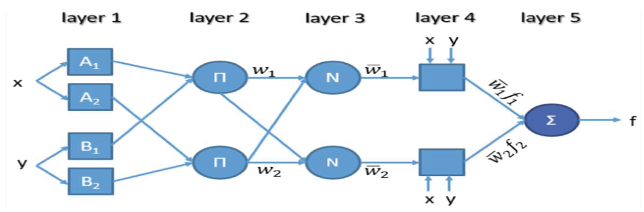
Figure 3.
ANFIS estimator design.
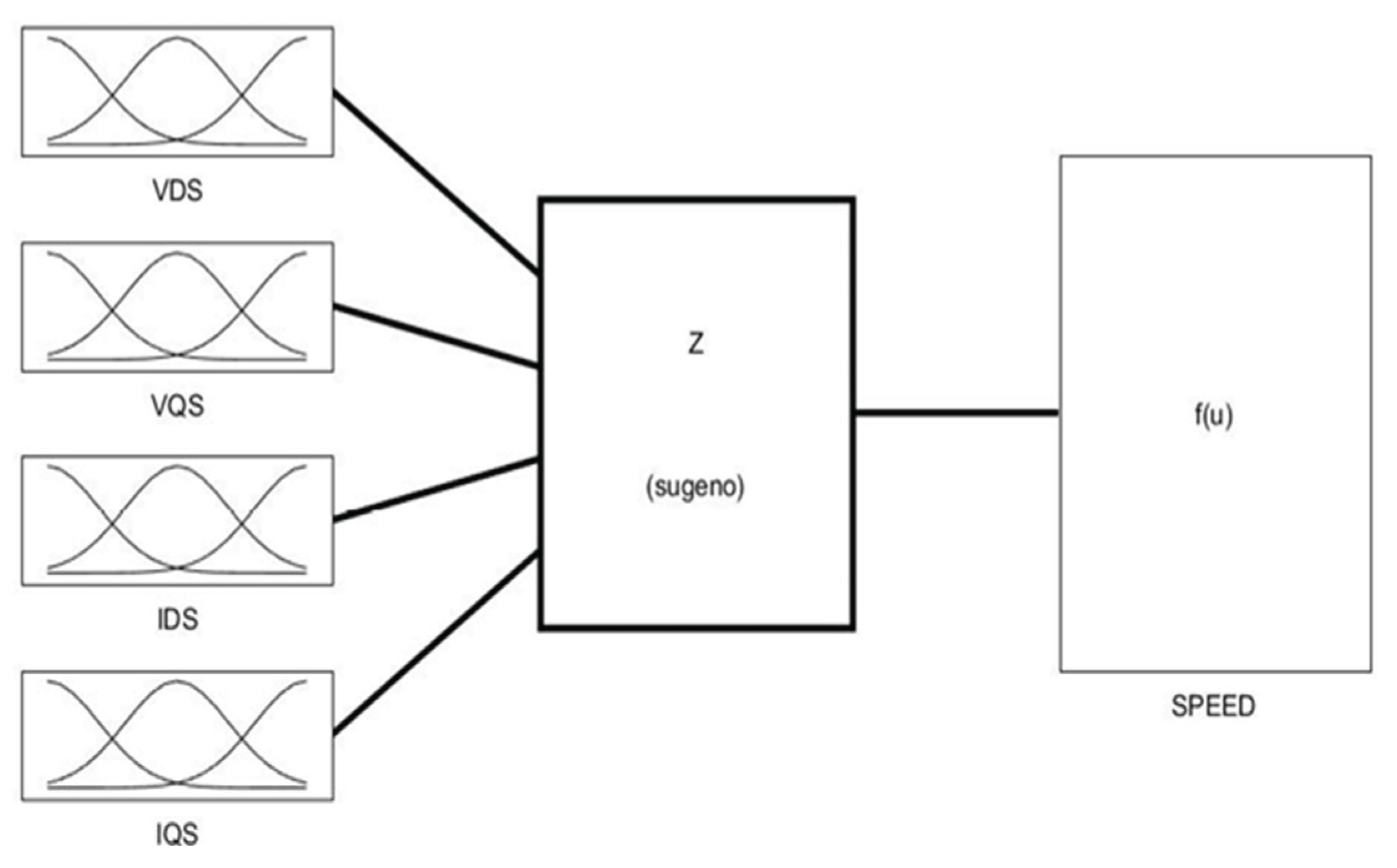
Figure 4.
ANFIS surface viewer.
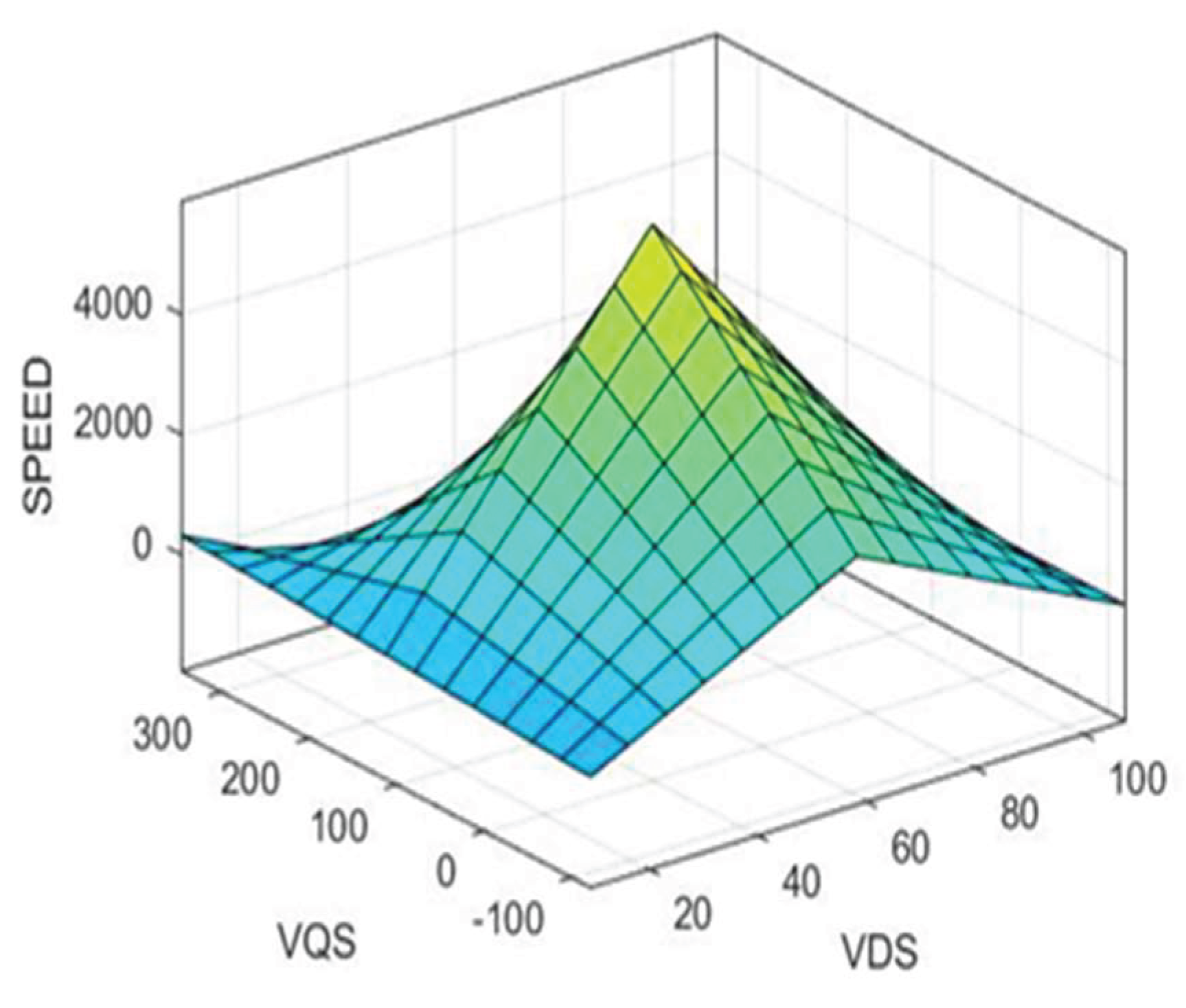
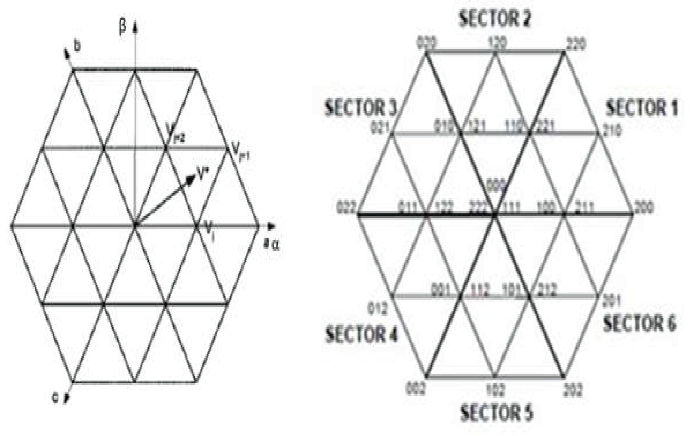
Figure 7.
Overall scheme used for Matlab simulation.
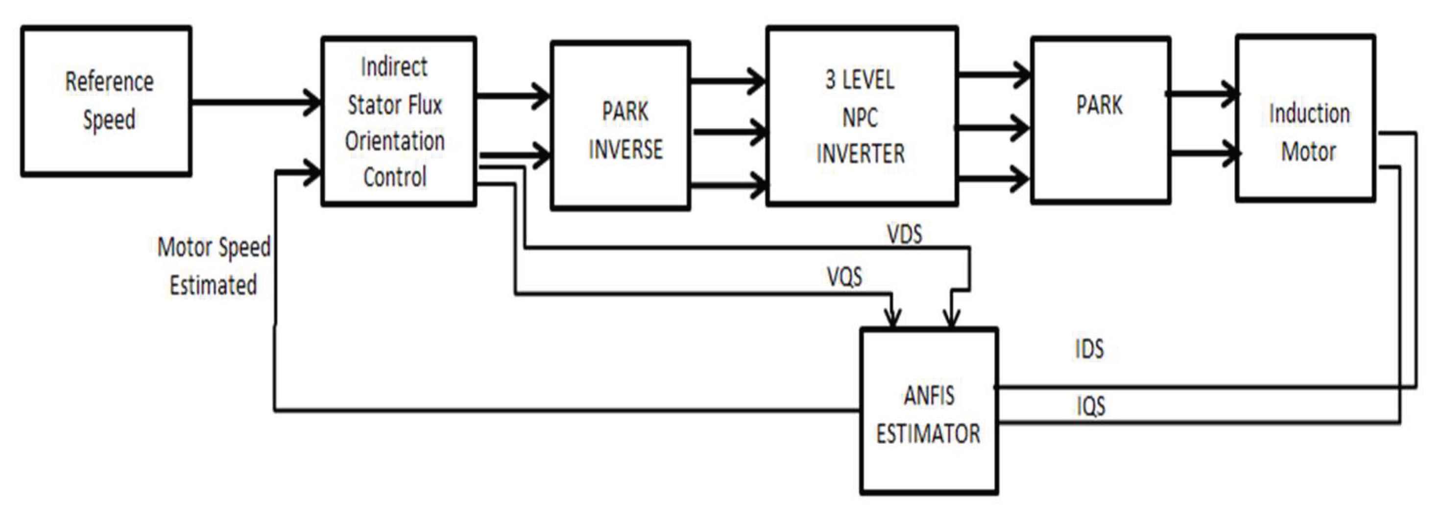
Figure 8.
Estimated speed response.
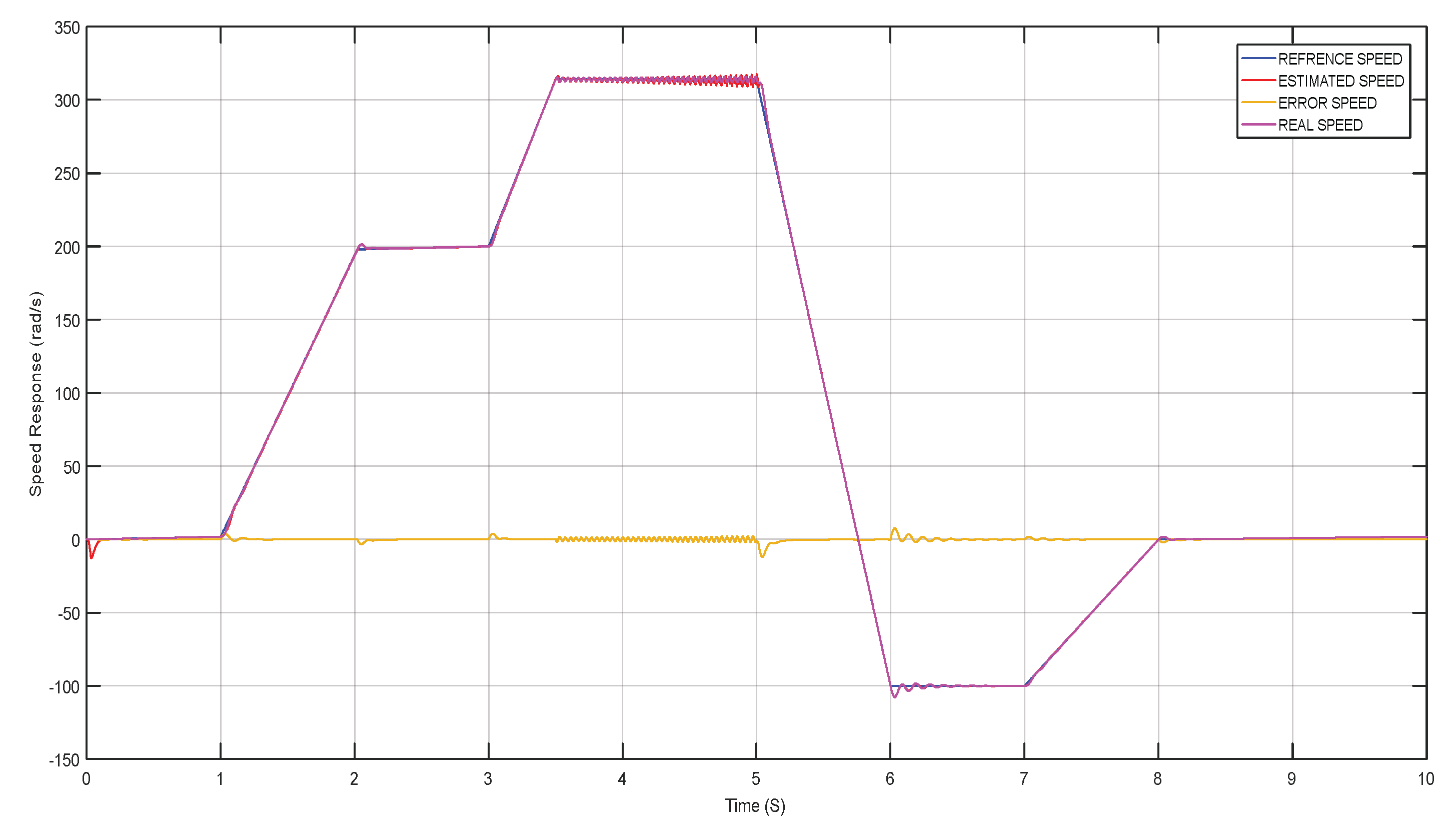
Figure 9.
D-axis and Q-axis Flux FDS & FQS.
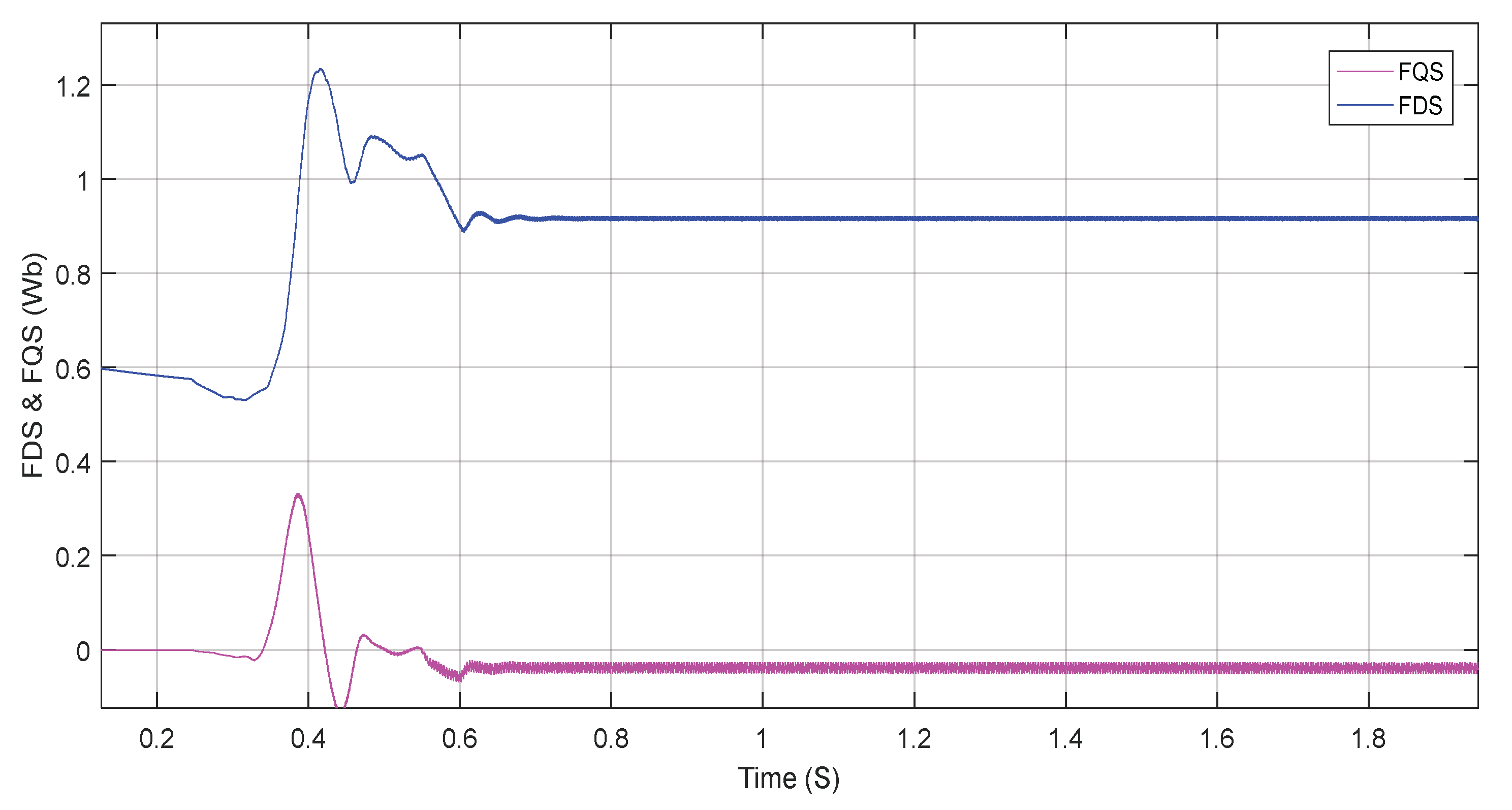
Figure 10.
Phase to Neutral Voltage of the inverter controlled by SVM.
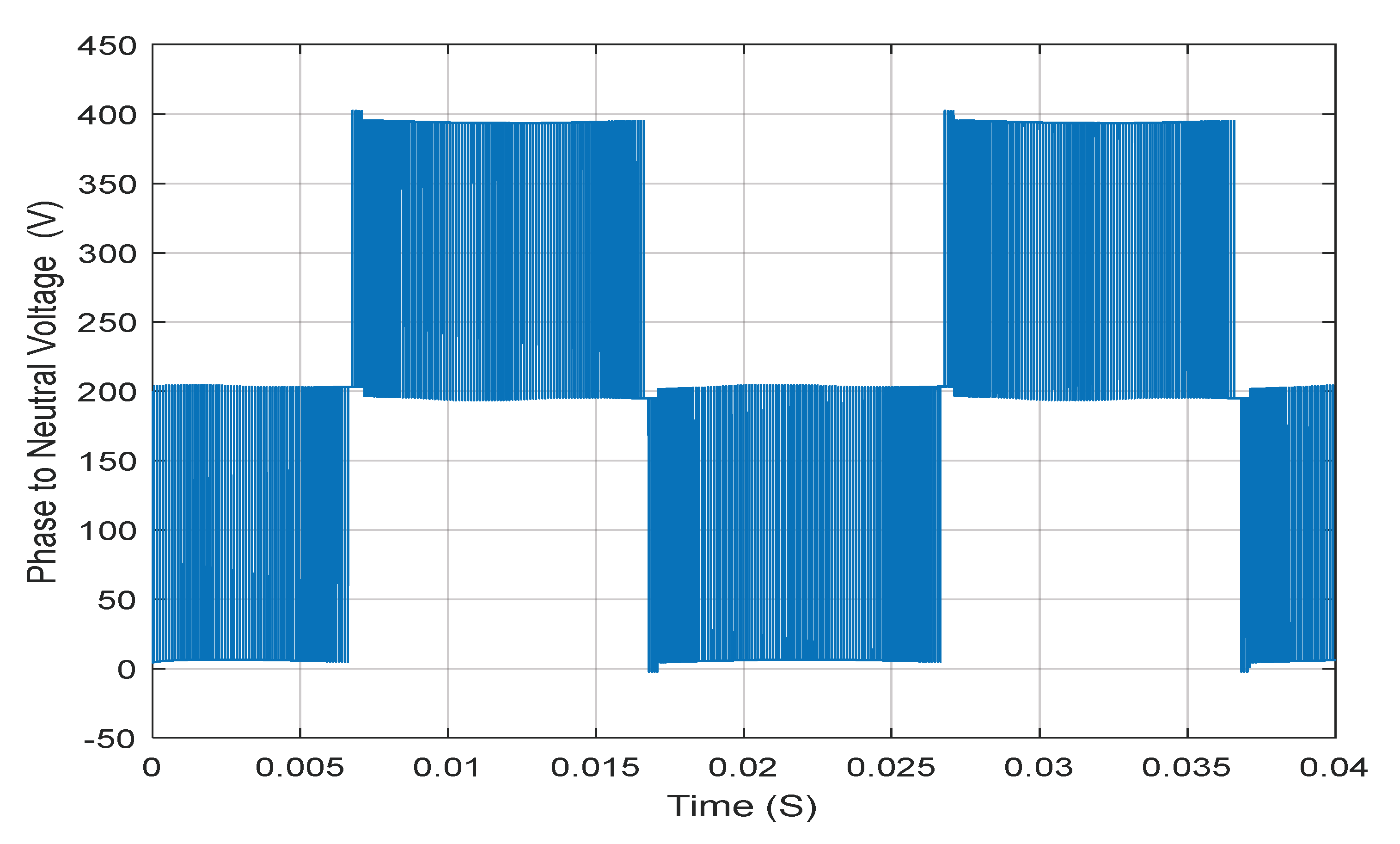
Figure 11.
Neutral to phase Voltage of the inverter controlled by SVM.
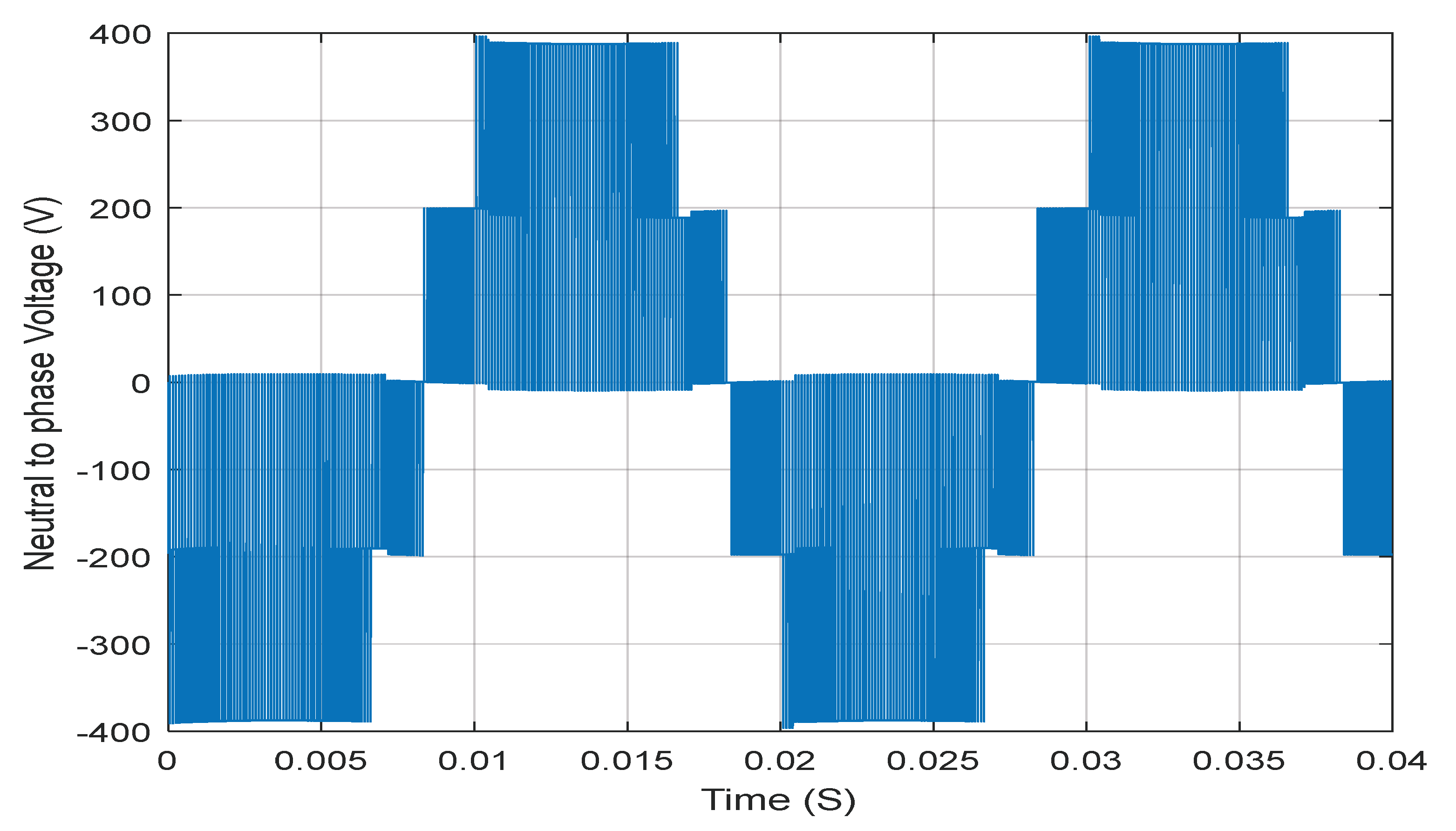
Figure 12.
Phase current of the inverter controlled by SVM.
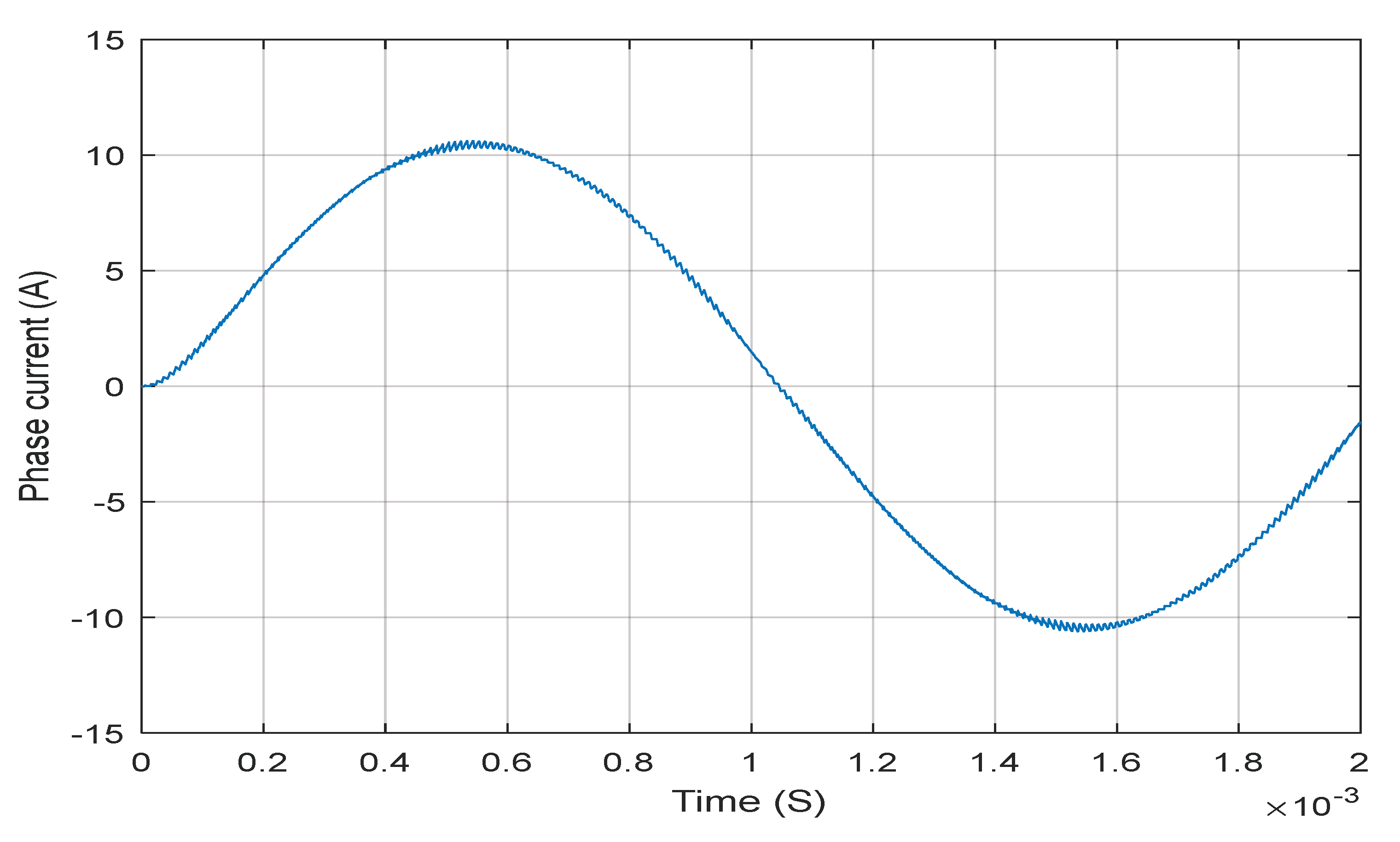
Table 2.
Suggested ANFIS parameters.
| Parameter | Design |
|---|---|
| Type | Sugeno |
| Inputs number | 4 |
| Number of membership functions for inputs | 3 |
| Membership function of input | type trimf |
| Number of Outputs | 1 |
| Number of rules | 81 |
Table 3.
Proposed NPC inverter switching state.
| C1 | C2 | C3 | Van | Vbn | Vcn | Vα | Vβ | Vab |
|---|---|---|---|---|---|---|---|---|
| 0 | 0 | 0 | 0 | 0 | 0 | 0 | 0 | 0 |
| 0 | 0 | 1 | 0 | |||||
| 0 | 0 | 2 | - | - | 0 | |||
| 0 | 1 | 0 | ||||||
| 0 | 1 | 1 | - | 0 | ||||
| 0 | 1 | 2 | 0 | |||||
| 0 | 2 | 0 | ||||||
| 0 | 2 | 1 | 0 | |||||
| 0 | 2 | 2 | 0 | |||||
| 1 | 0 | 0 | 0 | |||||
| 1 | 0 | 1 | ||||||
| 1 | 0 | 2 | 0 | 0 | ||||
| 1 | 1 | 0 | - | 0 | ||||
| 1 | 1 | 1 | 0 | 0 | 0 | 0 | 0 | 0 |
| 1 | 1 | 2 | 0 | |||||
| 1 | 2 | 0 | 0 | 0 | ||||
| 1 | 2 | 1 | ||||||
| 1 | 2 | 2 | - | 0 | ||||
| 2 | 0 | 0 | - | - | 0 | |||
| 2 | 0 | 2 | ||||||
| 2 | 0 | 1 | 0 | |||||
| 2 | 1 | 1 | 0 | |||||
| 2 | 1 | 2 | ||||||
| 2 | 2 | 0 | 0 | |||||
| 2 | 2 | 1 | 0 | |||||
| 2 | 2 | 2 | 0 | 0 | 0 | 0 | 0 | 0 |
Disclaimer/Publisher’s Note: The statements, opinions and data contained in all publications are solely those of the individual author(s) and contributor(s) and not of MDPI and/or the editor(s). MDPI and/or the editor(s) disclaim responsibility for any injury to people or property resulting from any ideas, methods, instructions or products referred to in the content. |
© 2025 by the authors. Licensee MDPI, Basel, Switzerland. This article is an open access article distributed under the terms and conditions of the Creative Commons Attribution (CC BY) license (http://creativecommons.org/licenses/by/4.0/).
Copyright: This open access article is published under a Creative Commons CC BY 4.0 license, which permit the free download, distribution, and reuse, provided that the author and preprint are cited in any reuse.


