
Submitted:
28 March 2025
Posted:
28 March 2025
You are already at the latest version
Abstract
This study introduces a torque distribution control system for a three-disc axial flux permanent magnet synchronous motor (AFPMSM) using a genetic algorithmoptimized back-propagation neural network (BP_ANN_GA) and an Adaptive Neuro-Fuzzy Inference System (ANFIS)-based torque control. These controllers enhance torque accuracy, reduce energy losses, improve motor sta-and performance, and meet the demands of modern EVs by advancing efficient transmission technology. The BP_ANN_GA controller predicts torque distribution (Tm1, Tm2, Tm3) based on speed and required torque (T*m), with a genetic algorithm optimising the network’s weights and biases to minimise mean squared error (MSE) for greater accuracy. The ANFIS controller combines fuzzy logic for stator current control with real-time ANN adjustments to minimise stator current errors using a 5x5 fuzzy rule matrix, regulating the inverter output voltage. This integration adapts to dynamic driving conditions, improving vehicle performance and energy efficiency. MATLAB/SIMULINK simulations validate the system, showing balanced torque distribution, reduced energy losses, enhanced drivetrain efficiency, and strong adaptability to load or road changes, ensuring stability and superior dynamic response.
Keywords:
Three-Disc AFPMSM
; GA_BP-ANN
; ANFIS
; GA
1. Introduction
The introduction should briefly place the study in a broad context and highlight its importance. It should define the purpose of the work and its significance. The current state of the research field should be carefully reviewed, and key publications should be cited. Please highlight controversial and diverging hypotheses when necessary. Finally, briefly mention the main aim of the work and highlight the principal conclusions. As much as possible, please make the introduction comprehensible to scientists outside your field of research. References should be numbered in order of appearance and indicated by a numeral or numerals in square brackets—e.g., [1]. See the end of the document for further details on references.
Axial flux permanent magnet synchronous motors (AFPMSMs) are increasingly favoured for electric vehicles due to their wide torque range, reduced pulsation, and high traction drive efficiency [2]. Multi-disc AFPMSMs are particularly suited for heavy-duty vehicles like buses and trucks, offering high torque and power density, compact design, efficient energy conversion, effective heat dissipation, reliability, and compatibility with advanced control and energy regeneration technologies. Optimised coil and magnet arrangements in AFPMSMs provide greater power density than radial flux motors, especially in multi-disc designs [3], making them ideal for high-power applications requiring strong starting and acceleration torque [4]. Their compact design also supports integrated drive systems, combining the motor, drive, and controller into a single unit to save space, reduce costs, and deliver high performance across a wide speed range [5].
AFPMSMs perform well across various speeds, making them ideal for high-power electric vehicles requiring flexible speed and torque control [6]. Research [7] shows that AFPMSMs, whether single or multi-stage, are easier to control than other permanent magnet synchronous motors. Advanced control systems like direct torque control (DTC) and model predictive control (MPC) enhance torque efficiency, conserve energy, and quickly respond to complex demands. However, the multi-stage structure of three-disc AFPMSMs requires precise coordination among discs for optimal torque distribution, posing challenges in control system design [8]. Synchronising magnetic flux stages demands advanced control systems and significant computational power, making integrated torque optimisation a key research focus [9]. Accurate mathematical models that account for factors like magnetic saturation, losses, and temperature effects are essential for optimal performance [10]. Intelligent control technologies, multi-objective optimisations, and precise modelling are critical to improving electric vehicles' energy efficiency, stability, and sustainability.
The complex nonlinear characteristics of multi-disc AFPMSMs, influenced by non-uniform magnetic flux, magnetic saturation, and inter-stage friction, require intelligent control methods such as Artificial Neural Networks (ANN), Fuzzy Logic Control (FLC), and Adaptive Neuro-Fuzzy Inference Systems (ANFIS) [11]. These methods manage nonlinearities and adjust torque without relying on precise motor models. Torque control in electric vehicles demands rapid responses to load and speed changes for smooth operation [12]. DTC provides immediate torque control, while optimised PID controllers (e.g., GA-PID, PSO-PID) ensure adaptability through parameter optimisation. FLC uses experience-based rules to adjust torque, making it suitable for unstable or poorly modelled systems, such as electric buses operating under complex conditions. However, FLC may lack accuracy under extreme or fluctuating inputs [13]. Combining FLC with MPC or ANN enhances stability, as ANN learns control rules from data to optimise torque distribution in multi-stage motors. However, extensive training data and high computational resources are required [14]. Sliding Mode Control (SMC) ensures stability by maintaining states on a predefined sliding surface, effectively handling disturbances and sudden load changes. While SMC provides quick, stable responses, it can cause signal chattering, which requires mitigation [15]. Optimised PID controllers, such as GA-PID and PSO-PID, use algorithms to determine optimal parameters for efficient torque control under varying conditions. However, they may struggle in rapidly changing, highly nonlinear environments [16]. ANFIS combines ANN and FLC to learn control rules from data, enabling real-time torque adjustments based on load and speed variations. This adaptability makes ANFIS ideal for electric buses, though it demands significant training data and computational time, particularly in rapidly changing conditions [17] and [18].
This paper proposes an integrated torque distribution control architecture for a three-disc Axial Flux Permanent Magnet Synchronous Motor (AFPMSM) system in electric vehicles (EVs) with the following novel contributions:
- ➢
- Intelligent Torque Distribution via BP-ANN and GA Optimization: A Backpropagation Neural Network (BP-ANN) predicts the individual torque of each AFPMSM unit based on total torque demand and speed. A Genetic Algorithm (GA) optimises the network’s weights and biases, reducing mean squared error (MSE) and improving accuracy. This approach ensures robust torque allocation even under highly dynamic driving scenarios like high speed or low load.
- ➢
- Adaptive Current Control with ANFIS-Based Regulation: An adaptive Neuro-Fuzzy Inference System (ANFIS) controller refines the overall torque output. It adjusts stator current references using fuzzy logic (5×5 rule base) combined with ANN feedback to minimize current control errors (id, iq). This allows better regulation of the inverter output voltage and improves the system’s adaptability to varying conditions.
- ➢
- Hybrid Control Framework for Enhanced Performance and Scalability: The system achieves coordinated control across three motor units by combining BP_ANN_GA for torque prediction and ANFIS for current regulation. This hybrid structure enhances energy efficiency, torque precision, and system stability and is scalable to multi-motor EV applications requiring real-time adaptive control under complex load profiles.
The paper is divided into five parts. Part 1 emphasises the need for improved motor efficiency in industrial applications, proposing torque control of the AFPMSM three-disc motor as a solution. Part 2 details the motor's mathematical model, including its structure, flux, and dynamic equations, with parameters derived from analysis and experiments. Part 3 introduces a control strategy integrating the BP_ANN_GA controller with the ANFIS controller to enhance accuracy, reduce computation time, and boost efficiency. Part 4 validates this approach through MATLAB simulations, and Part 5 concludes with a summary of findings, AI enhancement suggestions, and future research directions.
2. The Three-Disc AFPMSM Mathematical
The Materials and Methods should be described with sufficient details to allow others to replicate and build on the published results. Please note that the publication of your manuscript implies that you must make all materials, data, computer code, and protocols associated with the publication available to readers. Please disclose any restrictions on the availability of materials or information at the submission stage. New methods and protocols should be described in detail while well-established methods can be briefly described and appropriately cited.
The stator windings of this motor are chosen to capture the three-stator, double-rotor AFPMSM operation accurately. This facilitates the development of a mathematical model that closely resembles the conventional model used for PMSMs. The mathematical model developed for the three-disc AFPMSM is expressed within the framework of the three-phase stationary coordinate system, which provides a consistent basis for understanding its performance and integrating it with existing systems and technologies.
The voltage is calculated using Eq. (1):
The magnetic flux as defined in Eq. (2):
The torque of the three-disc AFPMSM is calculated using Eq. (3):
The torque of the three-disc AFPMSM is expressed as follows in Eq. (4):
In equations (1)–(4), are stator resistances, the d-q voltage components, the d-q current components, and the d-q inductances for stators 1–3. are d-q flux components, and are the torques, and and are the load torque for all stators.
The moment of inertia is J, and B represents viscosity and load torque. With two stators sharing a rotor, speeds occur. Three stators driving two coaxial rotors make the three-disc AFPMSM equivalent to three coaxial single-stage AFPMSMs. Identical stators share the d-q frame, symmetry ensuring and a uniform air gap, .
The torque equation can be expressed as:
where: Tm is the total electromagnetic torque of the motor, composed of the electromagnetic moments , from stators 1, 2, and 3. The iq1, iq2, and iq3 coils represent the q-axis components of the stator coil current vectors for stators 1, 2, and 3.
A three-disc AFPMSM mathematical BP_ANN_GA optimal torque controller and Stator Current controller’s design
Optimal torque control structure for a three-disc AFPMSM, as illustrated in Figure 1 and Figure 2 [10].
Figure 1 shows the interconnection structure of a three-disc AFPMSM drive system. The multi-disc AFPMSM motor features three independent stator windings, requiring three motor controllers. Conventional electric vehicle controllers can improve the system's efficiency through communication management. The first vehicle controller sends commands to the communication management unit, which assesses the motors' operating states and torque intensity according to predefined control strategies and distributes control signals and torque data to the three motor modules.
Figure 2 illustrates the torque control system for the Axial Three-Disc Permanent Magnet Synchronous Motor (AFPMSM). The input torque (Tm) is processed by the Thesis Torque Converter, dividing it into three components (Tma1, Tma2, Tma3) for the motor's three discs. These components are optimized in Torque Optimization blocks to improve performance and analysis. The optimized torque is converted into stator currents (isq1, isq2, isq3) to drive each motor section. Independent motor controllers (Motor Controllers 1, 2, 3) ensure each disc receives precise currents for desired torque, maintaining stability and preventing imbalances. Advanced algorithms such as PID-GA, ANFIS, or BP-ANN-GA can be integrated for further optimization and enhanced performance.
The torque of the three-disc AFPMSM is the sum of the three independent AFPMSM torques, determined using Eq. (6):
The total input power is given by Eq. (10):
The total output power is defined by Eq. (11):
Eq. (12) system performance depends on input-output interactions, enabling insights for optimization, scalability, and reliability.
3. The BP-ANN_GA Optimal Torque Control Design
The optimal torque distribution control for the three-disc AFPMSM motor, shown in Figure 3, uses a GA-optimized BP_NN to allocate torques (Tm1, Tm2, Tm3) among the discs based on input parameters like total required torque (T*m) and motor speed. The GA enhances the BP_ANN algorithm to predict the torques sent to each disc’s current controller (id, iq) to generate the actual torque, ensuring the total matches the required value. Trained offline with diverse operating conditions, the GA-optimized BP_NN ensures robust performance. It processes input parameters in real-time during operation, enabling fast, accurate torque distribution. This method improves dynamic response, reduces torque ripple, and ensures balanced thermal and mechanical loads across the discs.
3.1. Backpropagation Neural Network.
The BP_ANN network consists of three layers: an input layer with motor speed and total required torque, a hidden layer with adjustable neurons to model nonlinear input-output relationships using the ReLU (Rectified Linear Unit) activation function f(x) = max (0, x), and an output layer that generates three torques (Tm1, Tm2, Tm3) for AFPMSM motors. The weights and biases, which require optimisation, include:
- Weights between the input and hidden layers: .
- Weights between the hidden and output layers:
- Biases of the hidden and output layers:
As per Eq. (12), the total power input must be reduced to improve system efficiency. Permit is obtained by minimising a value and calculating the parameters at this minimum. This study uses a three-layer BP-ANN with two neurons in the input layer (torque sum and rotational speed ω), four in the hidden layer, and three in the output layer corresponding to .
The equation for calculating the hidden layer is:
ΩThe network's weights are updated through slope reduction to minimize repetition times. Coefficients are optimized using the negative gradient of the performance index, as defined in Eq. (19), where η is the learning rate, ∇J(w) is the gradient, and α is the momentum factor. This ensures stability and avoids local minima. Backpropagation employs the chain rule to calculate error gradients in hidden layers, adjusting weights until the performance index meets a threshold or the maximum iterations are reached.
Equation above is called learning speed and is a preset constant to control the speed of the weight-adjusting connection. It can be seen from the formula of the algorithm to reduce the slope that when the error approaches 0, there will be a tendency towards zero, which will cause the connection weight to no longer be updated. Weight gain is currently the optimal information the neuron learns in the network. The connection weight between the output layer and the hidden layer at time t+1 is:
The weighted learning algorithm functions by connecting the hidden layer and the input layer, thereby creating a structured and organized interaction between them. This interaction is specifically outlined and detailed in Eq. (19), which clearly describes how the connection is established and maintained.
At time step t+1, the hidden layer interacts with the weight input layer via a specific mechanism, preserving their functional connection, as shown in Eq. (22).
In a slope reduction algorithm, if the η setting is too large, the error may oscillate within a specific range. If η is too small, the error can settle into a local minimum, where the gradient approaches zero, a phenomenon known as gradient disappearance, preventing the performance function from reaching the global optimum. To avoid oscillations and gradient loss, a momentum coefficient α (0 < α < 1) is introduced, with α set to 0.05.
Eq. (23) is shown that this adjusts the weight changes effectively. The change in current weight depends on the previous weight shift. If 1w(t) > 0, the weight change is correct and can be accelerated. If 1w(t) < 0, the weight shift is restrained to avoid moving in the wrong direction, preventing oscillations and local minima.
3.2 Gennetic Algorithm Optimal for Weights and Bias
The Genetic Algorithm (GA) optimises the weights and biases of the Backpropagation Neural Network (BP_NN) to minimise the error between the network's predicted moment (Tpred) and the actual moment (Ttrue). By iteratively refining these parameters based on a Fitness Function that evaluates error minimisation, the GA improves the BP_NN's predictive accuracy. The optimisation workflow is detailed in the GA algorithm flowchart in Figure 4, which outlines the steps for convergence toward optimal values. The implementation, developed in MATLAB, efficiently utilises its computational. capabilities.
The PB_NN optimisation framework in MATLAB is designed to fine-tune system parameters for maximum efficiency under given conditions. Key parameters include ten hidden neural network nodes, a population size of 50 for optimisation diversity, and a maximum of 100 generations to achieve convergence. A function tolerance of 1 is set to terminate the process once the desired threshold is reached. The motor maintains a speed of 2000 rpm, with 200 Nm of applied torque. Figure 5 and Figure 6 illustrate the optimal torque response over time and system performance across various operational loops.
Case 1: Initial torque distribution (before GA optimisation):
Significant discrepancies exist between predicted and actual torques (Tm1, Tm2, Tm3). Initial Mean Squared Error (MSE): 0.7658. The average errors are below:
- Tm1: 0.3816 Nm.
- Tm2: 0.4685 Nm.
- Tm3: 0.0369 Nm.
Thus, the overall average error is 0.2957 Nm.
Case 2: Optimal torque distribution (after GA optimisation):
Predicted torques align nearly perfectly with actual values. The optimal MSE is 2.83x10⁻¹⁰ Nm², showing significant improvement. Average errors:
- Tm1: 0.0000 Nm
- Tm2: 0.0000 Nm.
- Tm3: 0.0000 Nm.
Therefore, the overall average error is 0.0000 Nm.
The GA method's optimisation process reduces the average torque errors for Tm1, Tm2, and Tm3 to zero, perfectly aligning predicted values with actual measurements. This eliminates discrepancies, lowering the average error from 0.2957 Nm to 0.0000 Nm. This remarkable improvement underscores the GA method's precision and effectiveness in enhancing prediction accuracy and performance.
Figure 5 compares torque distribution before and after optimisation using a Genetic Algorithm, highlighting the changes achieved. Figure 6 presents performance graphs showcasing the evolution and improvement of performance metrics over successive algorithm iterations.
Figure 5 compares torque distribution before and after the Genetic Algorithm (GA) optimisation. In the initial state (left plot), predicted torque values for T1, T2, and T3 deviate significantly from actual measurements, particularly at lower speeds. This causes performance instability, reduced efficiency, and unreliable motor control. These discrepancies highlight the need for a robust optimisation method. However, after GA optimisation (right plot), the predicted torque values (T1, T2, T3 - Optimized) align closely with actual measurements, with minimal errors even at low speeds. This improved accuracy enhances system stability, motor control performance, and efficiency. The results demonstrate the GA’s effectiveness in reducing prediction errors, refining torque distribution, and improving system reliability and functionality.
The results in Figure 6 show that the three-disc has characteristics. In the initial phase (Iteration < 20), both Training Loss and Validation Loss decrease significantly, indicating that the model is learning effectively and adjusting its weights efficiently. Initially, the Validation Loss is higher than the Training Loss, suggesting that the model is gradually improving its generalisation on the validation dataset. As the model reaches the stable phase (Iteration > 20), both Training Loss and Validation Loss fluctuated slightly around a stable level, indicating that the model has converged. The small fluctuations between Training Loss and Validation Loss confirm that the model does not suffer from overfitting. Regarding Testing Loss, the green dashed-dotted line remains stable at a fixed level, slightly higher than both Training Loss and Validation Loss. This difference could be due to variations in the test dataset, but since the gap is not too large, it suggests that the model still generalises well to unseen data.
Therefore, this study's results show that the model is learning effectively. Training and Validation losses decrease significantly at the beginning and converge over time. There are no signs of severe overfitting, as Validation Loss does not increase while Training Loss continues to drop. The testing loss remains stable, confirming that the model maintains a good generalisation performance.
The bar chart above compares the average output errors of the standard BP_NN and GA-BP_NN for torque components Tm1, Tm2, and Tm3 and the total error in Figure 7.
Figure 7 shows the impact of the Genetic Algorithm (GA) on reducing model errors in T1, T2, and T3. While GA reduces errors in T1 and T2, they remain relatively high compared to ideal levels. However, the algorithm significantly improves the T3 component, yielding a notable reduction in T3 error, substantially lowering the model's total error. This improvement enhances the neural network's accuracy and predictive reliability, particularly for T3. The results confirm GA's effectiveness in minimising mistakes and improving the model's performance.
Optimised weights for the GA_BPANN algorithm are shown in Table 1, and optimised biases are in Table 2.
The results from Table 1, Table 2, and Figure 8 show that the GA-optimized weights range between -0.5 and 0.5, encompassing both positive and negative values. This indicates the GA effectively minimized prediction errors by fine-tuning model parameters to reduce inaccuracies. Similarly, the optimized bias values also fall within the same range, which is crucial in adjusting the neurons' activation thresholds. These adjustments enhance the neural network's ability to process information, adapt during learning and prediction phases, and improve accuracy and generalization to unseen data. Combining weights and biases strengthens the model's learning and predictive performance. Therefore, the proposed optimal torque control for the three-disc AFPMSM leverages a GA-optimized BP_NN and ANFIS for precise and balanced torque distribution (Tm1, Tm2, Tm3), energy-efficient operation, robust performance under varying conditions, and real-time adaptability. This approach suits electric vehicles well, ensuring efficiency, stability, and precision.
3.3. An ANFIS Torque Control Design for a Three-Disc AFPMSM
The structure of the ANFIS algorithm consists of five layers: the input layer, input member function layer, rule layer, output member function layer, and output layer. A fuzzy interference decision tree classifies data into one of the linear regression models (2n or pn) to minimise total squared error (SSE):
1st layer: the dimming process occurs; the input signal is dimmed into five inter-triangular functions. For each output value of the first class, we can easily calculate an associated function value denoted by . Where: i is the member level of the data set (A1, A2, B1, B2) and is the output of the ith node in layer 1.
2nd layer: the weight check of each function. In this class, the input values from the first class are taken and act as optimal functions to represent the data sets of the corresponding input variables. The output of this button is described as follows:
3rd layer: the rule layer and receives input from the previous layer. Each node (per neuron) in this class performs the conditional matching of the rules. This layer calculates the trigger level of each rule, and the number of layers is equivalent to the number of fuzzy rules. Each node of this class calculates the weight that will typically. 3rd layer nodes calculate the ratio of the trigger intensity of a rule to the sum of all triggering rules:
4th layer: fuzzy solution provides output values due to inference of regulations. The node output is calculated by multiplying the class 3 output value and the Fuzzy rule, respectively:
5th layer: the so-called output layer synthesizes all inputs from the 4th layer and converts the fuzzy classification results into sharp values.
4. Simulation Results
Figure 9 illustrates the optimal torque control structure for the three-disc AFPMSM in electric vehicles, implemented in MATLAB simulation. The optimal torque control structure for the three-disc AFPMSM motor in electric vehicles is implemented in MATLAB/SIMULINK.
This MATLAB simulation system is performed with the motor parameters, as Power is 160(kW); Rated speed is 3000 rpm; Rated voltage is 275(V); Number of poles is 6; Magnetic flux is 0.0437 (Wb); Max torque is 300(Nm); Stator resistance is 0.0101 (Ω); d-axis inductance is 0.00024 (H); q-Axis inductance is 0.000297 (H). The research will create two simulation scenarios to validate the proposed optimal torque control solution for the 3-disc AFPMSM drive system.
Figure 9 shows the optimal torque distribution system for the three-disc AFPMSM, utilising a traditional PI speed controller with Kp = 19.5 and Ki = 0.999, determined by the symmetrical optimisation criterion. This design ensures accurate speed regulation with minimal overshoot and steady-state error, balancing response speed and stability. The symmetrical optimisation criterion improves dynamic performance under varying loads or sudden speed changes. At the same time, the robust three-disc AFPMSM design ensures uniform torque distribution and avoids issues like flux weakening.
Scenario 1: The system operates with a load torque of 20Nm and accelerates from 0 rpm to 1100 rpm in 5 seconds.
The motor also accelerates from 0 rpm to 1100 rpm in 5 seconds. Figure 10, Figure 11, Figure 12 and Figure 13 illustrate the torque response, iq current response, 3-phase AC response, and motor speed response.
Figure 10 illustrates the motor's torque performance, peaking at 300Nm during startup. With 8% pulsation, torque increases from 0Nm to 50Nm in 0.5 seconds. The ANFIS-based controller enhances torque tracking, reducing ripple to below 2%, which is ideal for precision applications requiring smooth operation. Additionally, it reduces overshoot, improves stability, and ensures accuracy and reliability under varying conditions, such as load changes and parameter fluctuations, while minimising energy losses to optimise motor efficiency. By improving torque profiles, reducing harmonic distortion, and enhancing efficiency, the ANFIS-based controller delivers precision, stability, and reliability for advanced motor systems, making it well-suited for demanding applications.
Figure 12 shows that the current amplitude is stable at -200A to +200A, confirming that the system usually operates without signs of severe imbalance. The symmetrical current shows the motor operates efficiently without phase deviation or imbalance. A stable current amplitude helps the output torque not fluctuate strongly, ensuring motor efficiency. The stable current frequency shows that the controller is operating well and maintaining the system's stability.
The performance of the three-disc AFPMSM motor is evaluated by analysing the output torque and rotor shaft speed. Its efficiency is calculated using Eq. (30) to assess overall effectiveness, providing a comprehensive understanding of the system's capabilities. Figure 14 shows the three-disc AFPMSM performance with optimal torque via neural network control.
Simulation scenario one is designed to evaluate the performance of the motor system across a range of rotational speeds and torque values. The speed range spans from 300rpm to 1100rpm, with increments of 100rpm, resulting in a total of 9 distinct speed points being assessed. The motor is tested for each speed under varying torque conditions, starting from 0Nm and increasing in steps of 20Nm up to a maximum torque of 200Nm. This results in 10 different torque points being analysed at each speed. The simulation involves collecting data for 19 unique combinations of speed and torque, ensuring a comprehensive evaluation of the motor's performance under different operating conditions.
Figure 14 shows that motor efficiency is high within the rated speed range but decreases outside. At 1100rpm and 200Nm torque, system efficiency reaches nearly 90%, highlighting the importance of optimising motor operation within its designed speed and torque range. Beyond these limits, energy losses increase due to higher resistive losses from increased current at low speeds and more significant mechanical losses from friction and windage at high speeds. Effective control strategies, such as torque ripple minimisation and thermal management, are essential for maintaining efficiency under varying conditions.
Scenario 2: The system operates with a load torque of = 0Nm and accelerates from 0rpm to 2300rpm in 5 seconds.
Figure 15, Figure 16, Figure 17 and Figure 18 detail the results for torque response, iq current, 3-phase AC, and motor speed, respectively. These figures illustrate the motor’s performance and behaviour under the given conditions.
Applying the ANFIS controller has brought about outstanding efficiency in optimising the system response, significantly shortening the time to reach maximum torque and helping the motor start more quickly and efficiently, thereby improving the overall system efficiency. The result of the iq current response (Figure 16) is like case 1 (Figure11). Figure 16 shows that during the initial stage (0-0.5 seconds), the current spikes to 50A due to the high starting torque required, then rapidly drops. In the transient stage (0.5-2 seconds), the current gradually decreases with minor oscillations as the control process stabilises the system. In the stable stage (2-5 seconds), the current settles at 10A, demonstrating system stability and effective control without large oscillations. The results confirm a short transient stage, fast control response, and smooth motor operation with stable torque, preventing overload or imbalance.
During this operation, the system's three-phase sine waveform demonstrates a consistent and balanced amplitude across all three phases, indicating stable operation under load conditions. As expected, the phase displacement between each waveform remains at 1200, confirming the system's proper synchronisation, as shown in Figure 17. Additionally, no visible distortions or irregularities are present, suggesting minimal harmonic interference and efficient power delivery throughout the operation. The smooth sinusoidal shape further reduces electrical noise and optimises performance across connected components. Figure 17 shows that the motor reaches 2300rpm at idle within 3.5 seconds without overshooting, demonstrating the ANFIS controller's efficiency, stability, and precision. Its well-tuned parameters ensure a fast and accurate response while optimising performance. The absence of overshooting enhances stability, reduces mechanical wear, and conserves energy, meeting industrial requirements.
The efficiency map in Figure 18 illustrates the performance characteristics of the motor system across the tested speed and torque ranges. Motor efficiency peaks within the rated speed range and decreases outside it at 2300rpm and 200Nm torque; system efficiency reaches 93.3%. At 1500rpm and 250Nm torque, it slightly decreases to 91.7%. Under lower loads, such as 100 Nm torque and 1800rpm, efficiency remains at 92.5%. To maximise efficiency, the motor should operate within the optimal speed and load range, where torque and speed are balanced for peak performance. Operating conditions deviating significantly from the optimal range can reduce system efficiency and increase energy losses.
5. Conclusions
The study developed an integrated system for optimal torque distribution and motor control for electric vehicles in a three-disc AFPMSM, equivalent to three coaxial PMSM motors. Simulations showed that a genetic algorithm-optimized back-propagation neural network (BP_ANN_GA) improves efficiency and robustness through optimal torque distribution. The ANFIS current controller ensures fast settling time and minimal static error. MATLAB/SIMULINK simulations confirmed the system's stability, disturbance rejection, effective torque control and current regulation. However, the study is limited to MATLAB simulations and requires real-time HIL testing for excellent reliability. Future work will explore intelligent control methods with disturbance observers to reduce dependence on system parameters and improve performance and robustness. The system shows promise for advanced energy management in electric vehicles by optimising power use and extending battery life. Incorporating real-time adaptive control algorithms can enhance performance under varying loads and speeds, while predictive maintenance using neural networks can extend operating life and reduce downtime.
Acknowledgments
The authors thank the University of Transport and Communications for providing the necessary facilities and support, which were instrumental in completing this research.
Conflicts of Interest
The authors declare no conflict of interest. The study was conducted independently, without external influence on its design, analysis, or conclusions.
References
- Guangyu Zheng: Research on energy saving and emission reduction of urban transportation under low-carbon life, 3rd International Conference on Civil Architecture and Energy Science (CAES 2021), 248 (2021). [CrossRef]
- M. Zhu, X.-Y. Liu, F. Tang, M. Qiu, R. Shen, W. Shu, M.-Y. Wu, Public vehicles for future urban transportation, IEEE Trans. Intell. Transp. Syst., 17(12) (2016) 3344–3353. [CrossRef]
- X. Sun, C. Hu, J. Zhu, S. Wang, W. Zhou, Z. Yang, G. Lei, K. Li,B. Zhu, Y. Guo, MPTC for PMSMs of EVs with multi-motor driven system considering optimal energy allocation, IEEE Trans. Magn., 55(7) (2019) 8104306. [CrossRef]
- Z. Shi, X. Sun, Y. Cai, Z. Yang, G. Lei, Y. Guo, J. Zhu, Torque analysis and dynamic performance improvement of a PMSM for EVs by skew angle optimisation, IEEE Trans. Appl. Supercond., 29(2) (2019) 1–5. Available online: http://hdl.handle.net/10453/131822.
- X. Tang, W. Yang, X. Hu, D. Zhang, A novel simplified model for torsional vibration analysis of a series-parallel hybrid electric vehicle, Mech. Syst. Signal Process., 85 (2017) 329–338. [CrossRef]
- X.-L. Tang, X. Hu, W. Yang, H. Yu, Novel torsional vibration modelling and assessment of a power-split hybrid electric vehicle equipped with a dual-mass flywheel, IEEE Trans. Veh. Technol., 67(3) (2018) 1990–2000. [CrossRef]
- M. Aydin, M. Gulec, Y. Demir, B. Akyuz, E. Yolacan, Design and validation of a 24-pole coreless axial flux permanent magnet motor for a solar-powered vehicle, Proc. IEEE 22nd ICEM, Lausanne, Switzerland, (2016) 1493–1498. [CrossRef]
- J. Zhao, B. Li, Z. Gu, Research on an axial flux PMSM with radially sliding permanent magnets. Energies, 8(3) (2015) 1663–1684. [CrossRef]
- A. Hemeida, P. Sergeant, A. Rasekh, H. Vansompel, J. Virendeels, an optimal design of a 5MW AFPMSM for wind turbine applications using an analytical model, Proc. IEEE 22nd ICEM, Lausanne, Switzerland, (2016) 1290–1297. [CrossRef]
- Jianfei Zhao, li xiao zheng, shuang wang, mini hua, Research on Deadbeat Current Prediction Vector Control System of Axial Flux Permanent Magnet Synchronous Motor for Electric Bus Based on Efficiency Optimal Torque Distribution Method, (2019). [CrossRef]
- B. Nanda, Fuzzy Logic Based Field Oriented Control Of Permanent Magnet Synchronous Motor, International Journal of Electrical Electronics and Data Communication, (2015). [CrossRef]
- D. V.Lukichev, G. L. Demidova, A. Y. Kuzin, A. V. Saushev, Application of adaptive Neuro-Fuzzy Inference System (ANFIS) controller in servo drive with multi-mass object, 2018 25th International Workshop on Electric Drives: Optimization in Control of Electric Drives (IWED), Moscow, (2018) 1-6. [CrossRef]
- W.A. Salem, G.F. Osman, S.H. Arfa, Adaptive Neuro-Fuzzy Inference System Based Field Oriented Control of PMSM & Speed Estimation, 2018 Twentieth International Middle East Power Systems Conference” (MEPCON), (2018) 626-631. [CrossRef]
- Nguyen Van Hai, Vo Thanh Ha, Genetic Algorithm Turned PID Control of AFPMSM for Electrical Vehicle Application, SSRG International Journal of Electrical and Electronics Engineering, 11(2) (2024) 119-128. [CrossRef]
- Vo Thanh Ha, Nguyen Van Hai, Adaptive Neuro-Fuzzy Control of a Single-Sided AFPMSM Motor for Electric Vehicle Applications, SSRG International Journal of Electrical and Electronics Engineering, 11(4) (2024) 118-129. [CrossRef]
- Duy Hoang Dao, Trong Minh Tran, Thanh Ha Vo, Torque Control of an In-Wheel Axial Fux Permanent Magnet Synchronous Motor (AFPMSM) Using Adaptive Neuro-Fuzzy Inference System (ANFIS) for Electrical Vehicles Applications, JTE, 19(04) (2024). [CrossRef]
- N. S. Farhan, F. A. Hasan, A. R. D. Humud, Field-oriented control of AFPMSM for an electrical vehicle using adaptive neuro-fuzzy inference system (ANFIS), Engineering and Technology Journal, 39(10) (2021) 1571-1582. [CrossRef]
- Junxi Zhang, Shiru Qu, Optimization of Backpropagation Neural Network under the Adaptive Genetic Algorithm, July 2021, Hindawi Complexity Volume 2021, Article ID 1718234, 9 pages. [CrossRef]
Figure 1.
The interconnection structure of a three-disc AFPMSM [10].
Figure 1.
The interconnection structure of a three-disc AFPMSM [10].
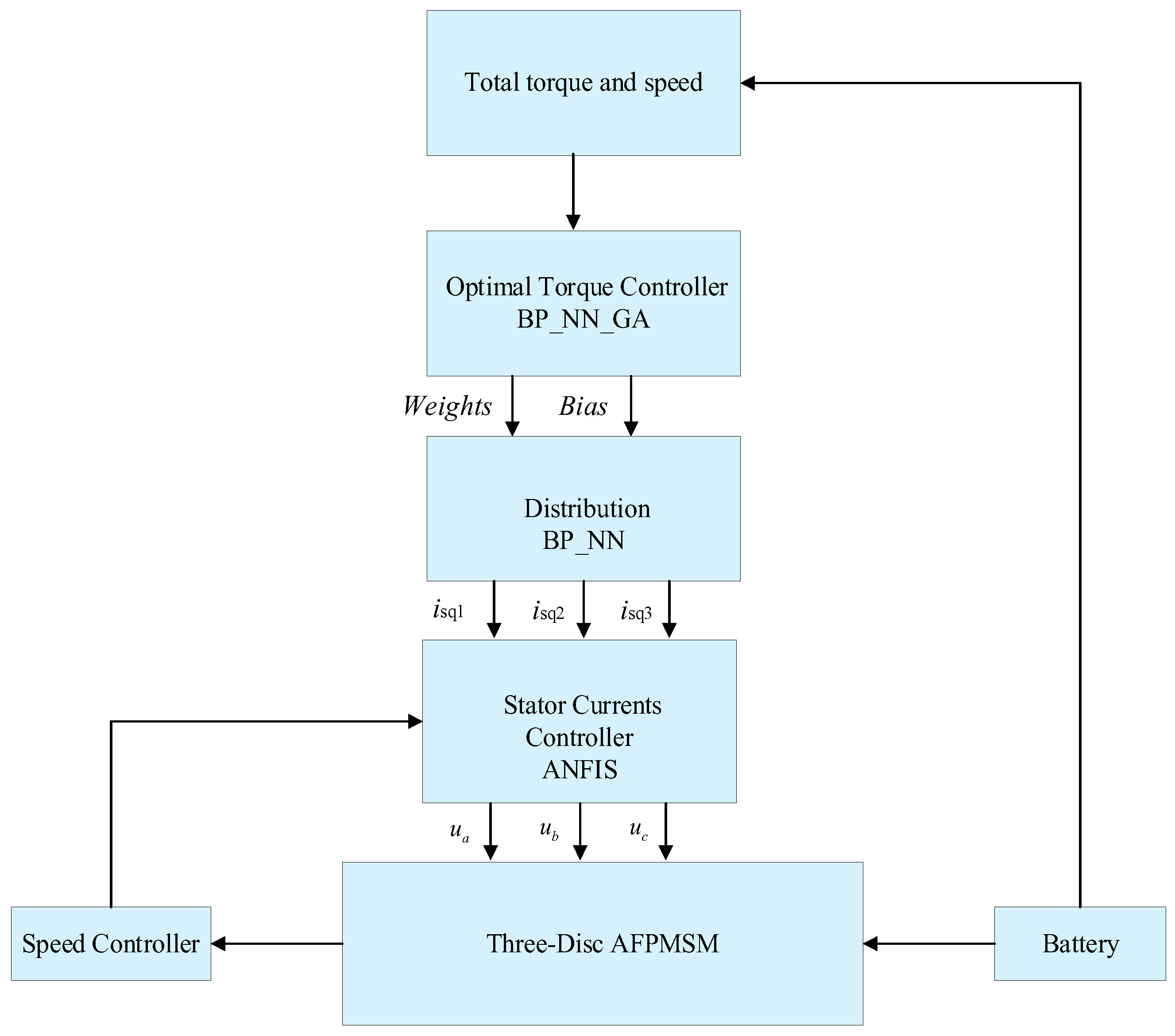
Figure 2.
The optimal torque control structure for a three-disc AFPMSM [10].
Figure 2.
The optimal torque control structure for a three-disc AFPMSM [10].
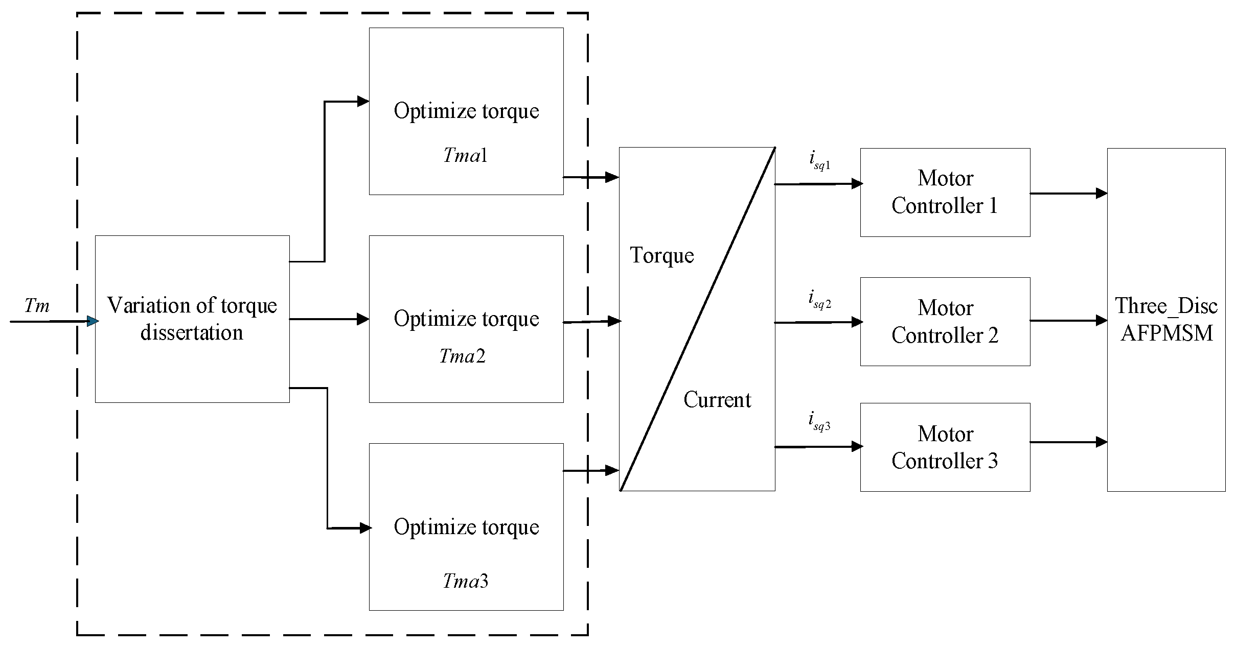
Figure 3.
The A BP-ANN_GA optimal torque control structure for a three-disc AFPMSM.
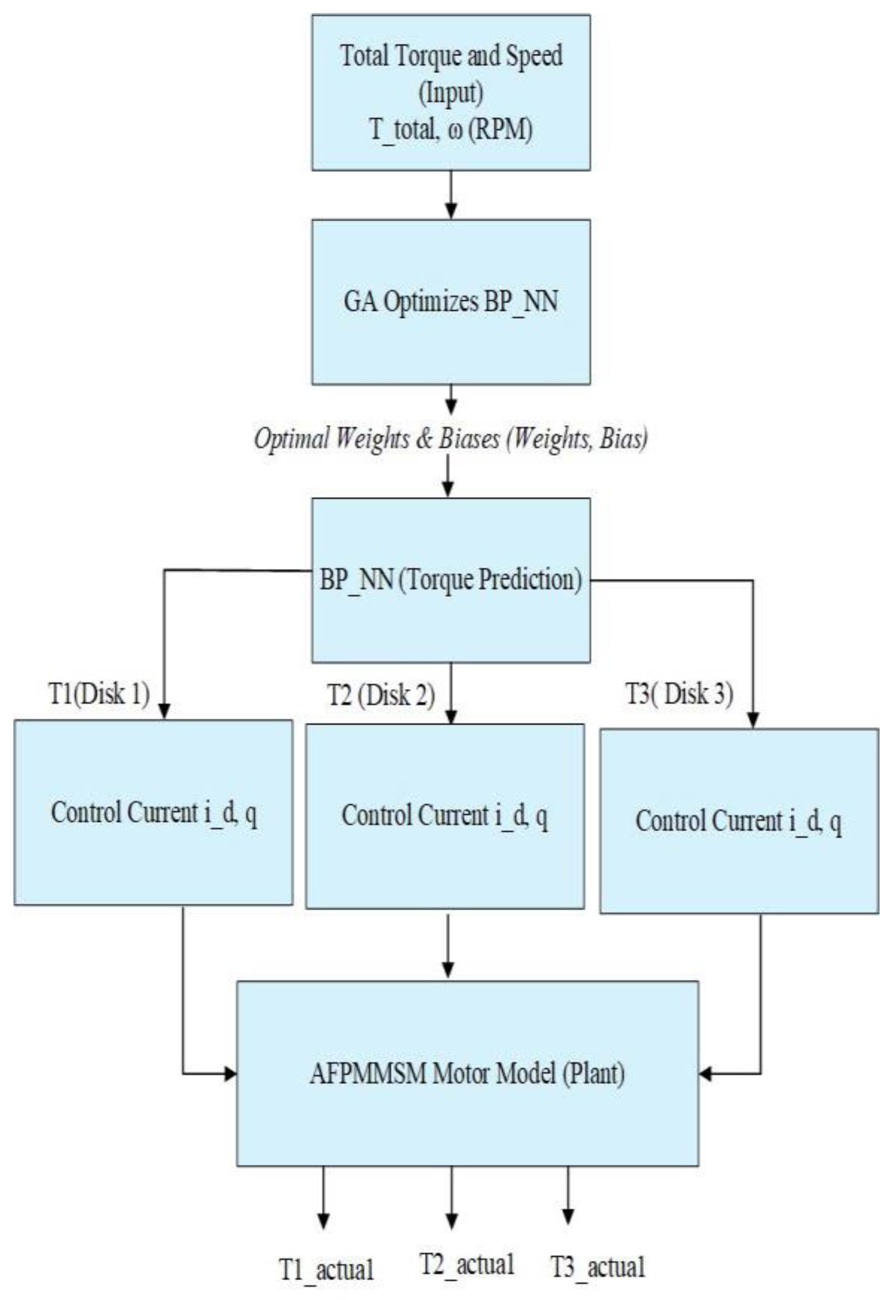
Figure 4.
The GA algorithm flowchart and codes ‘GA in MATLAB.
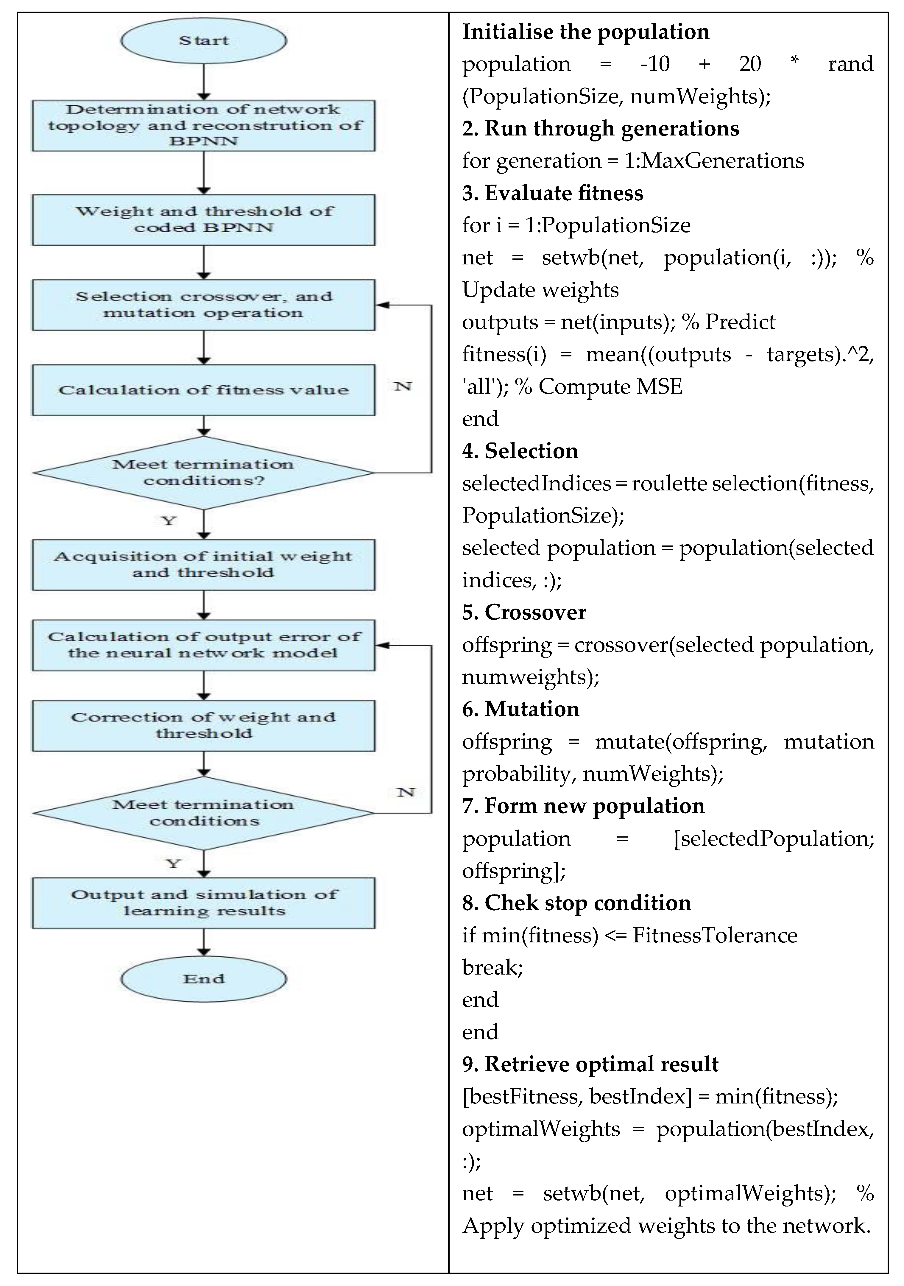
Figure 5.
The optimal torque response.
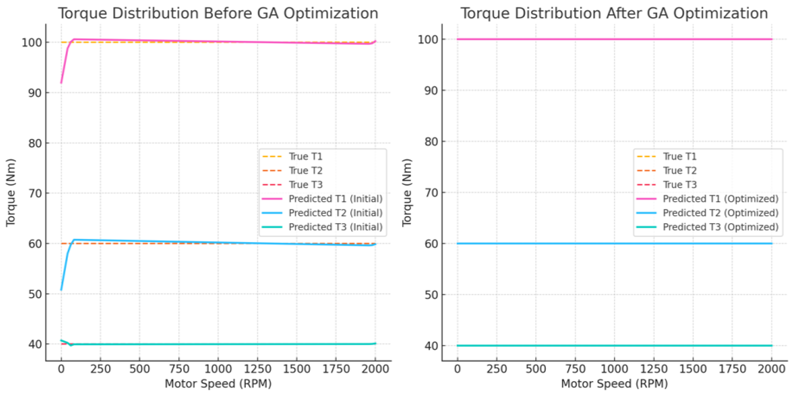
Figure 6.
The performance across loops.
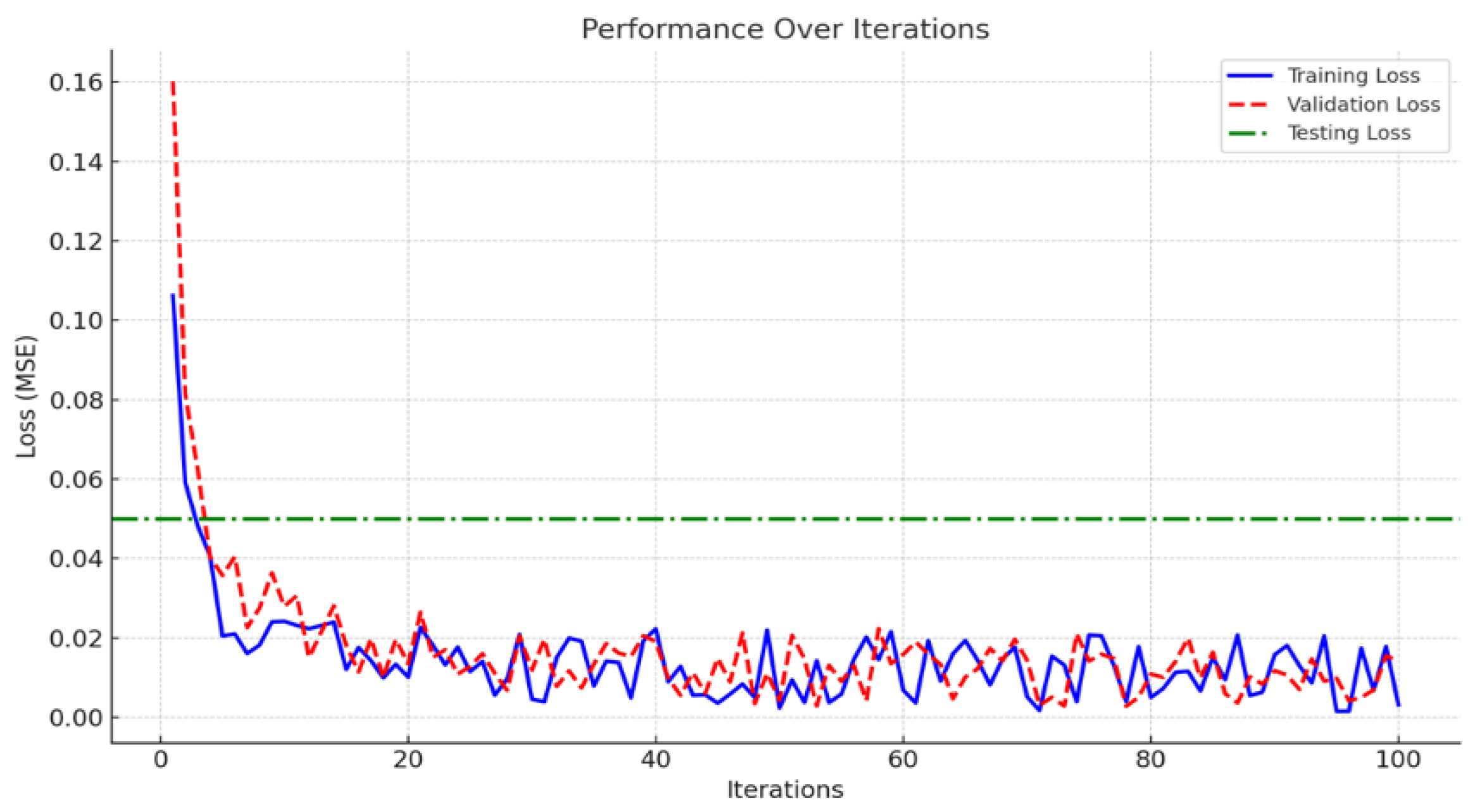
Figure 7.
The comparison of average output errors.
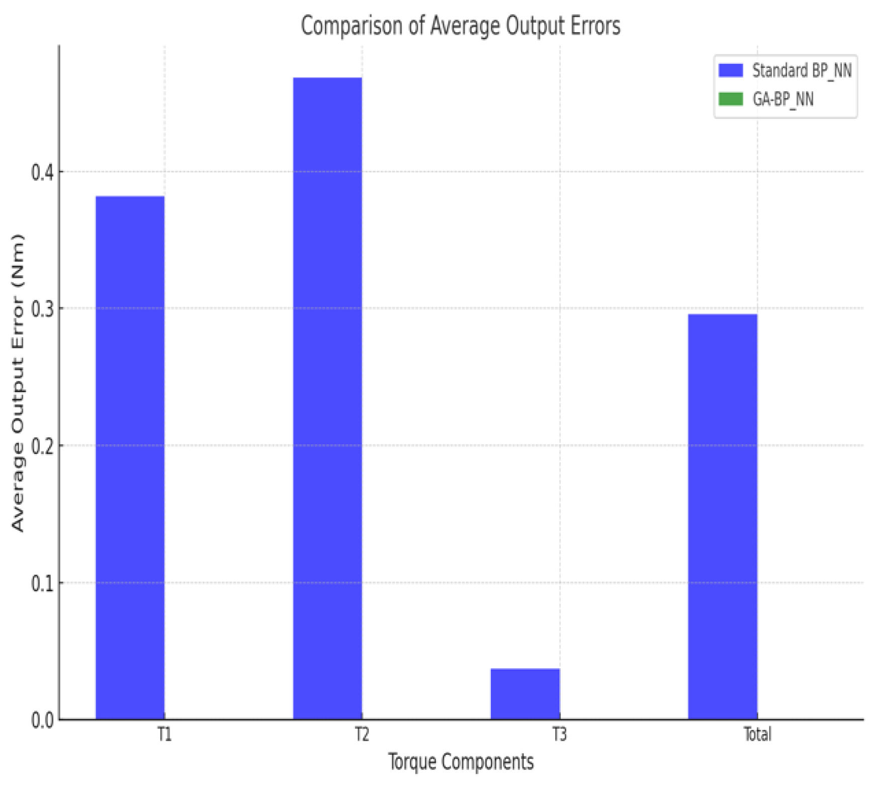
Figure 8.
Optimized weights and Biases for GA_BPANN.
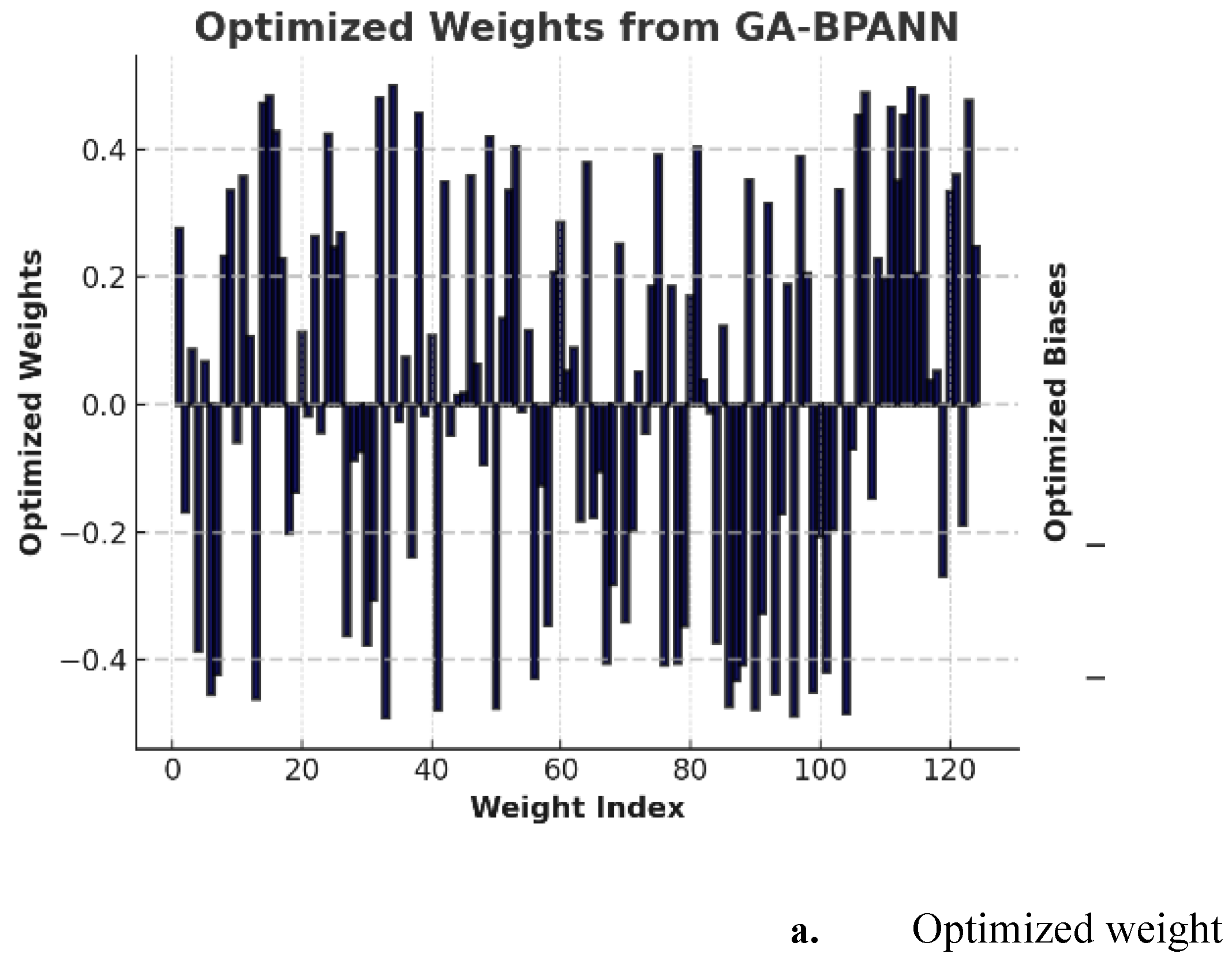
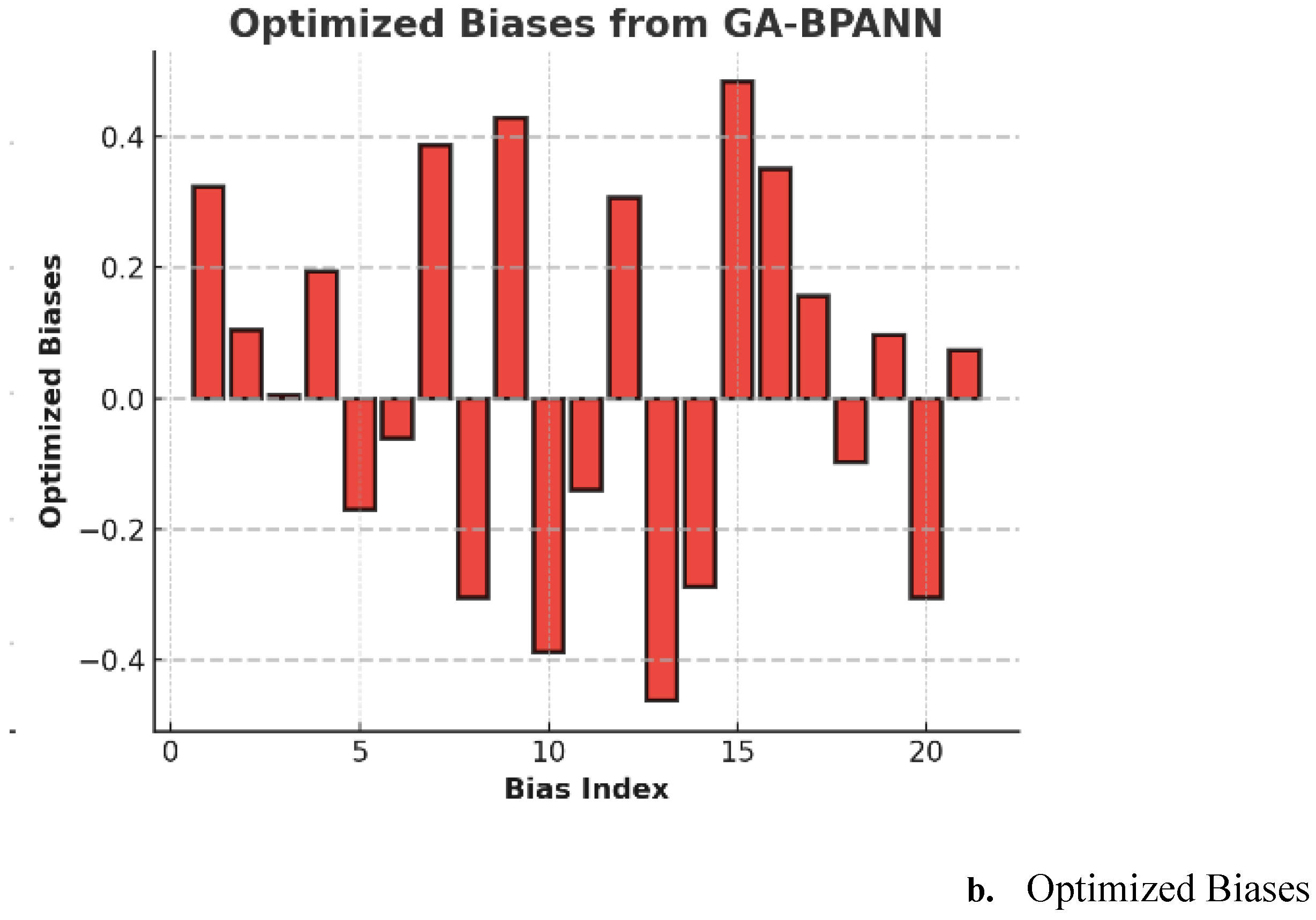
Figure 9.
The control structure of the three-disc AFPMSM motor.
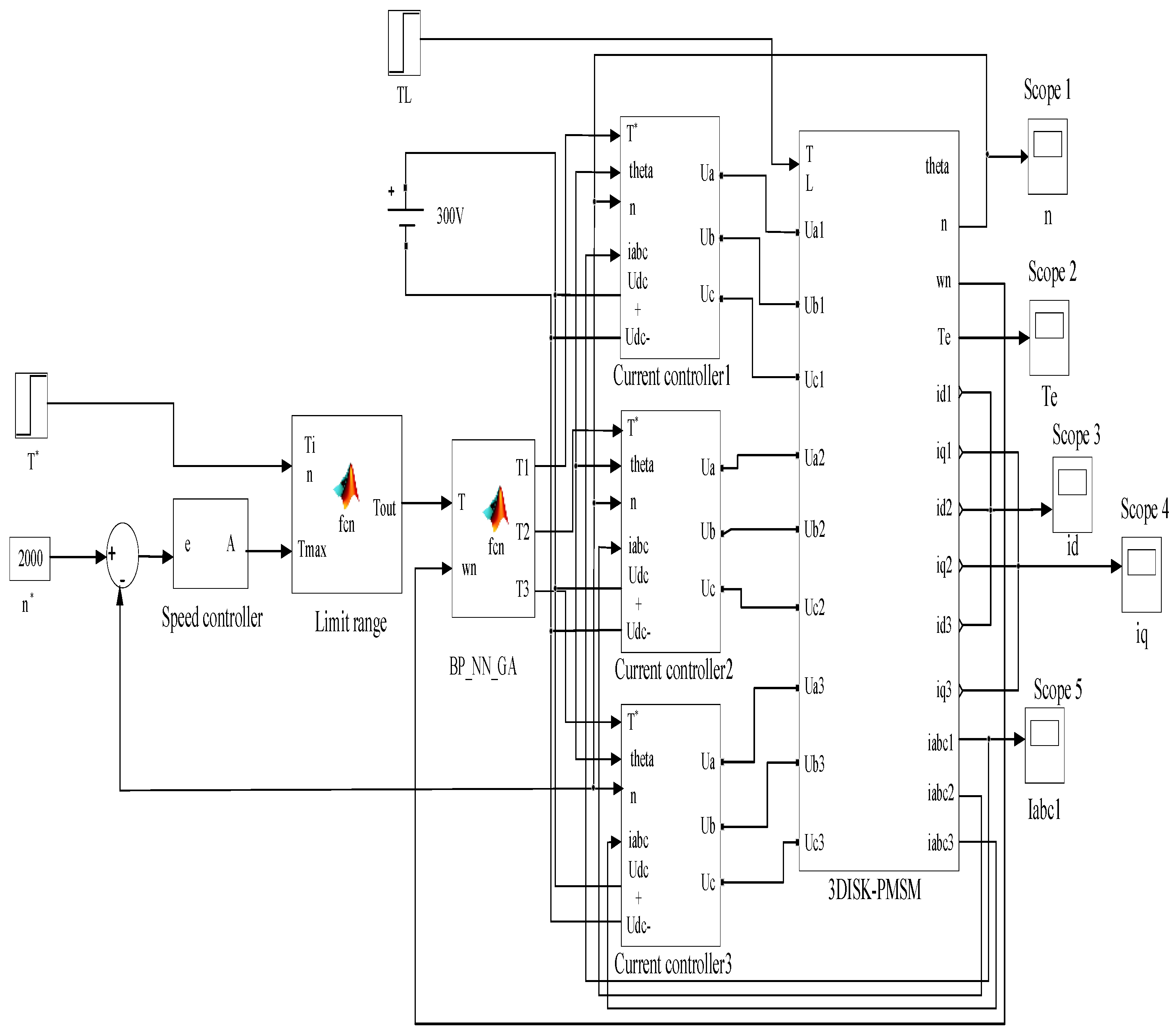
Figure 10.
The torque response.
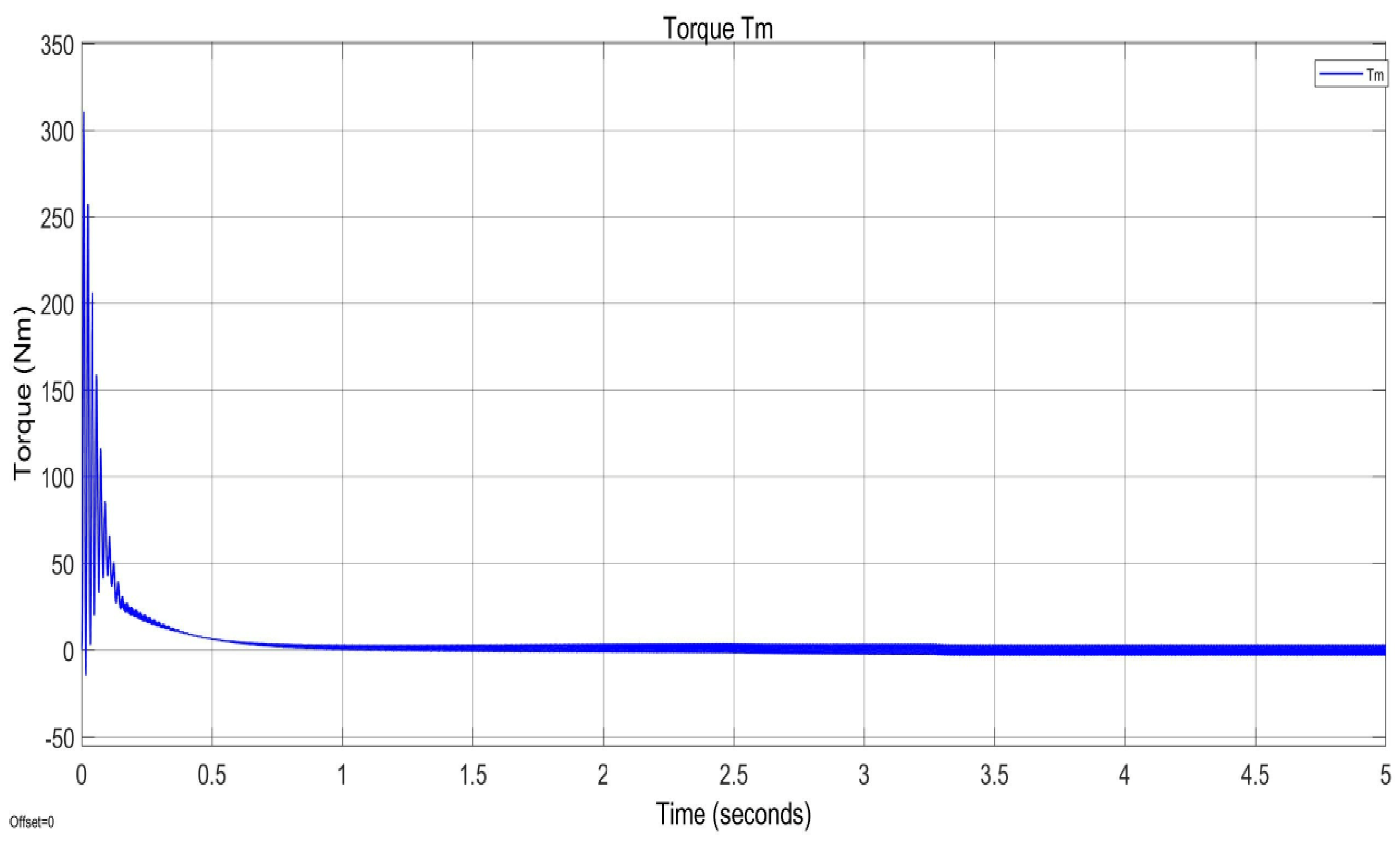
Figure 11.
The iq current response.When iq is controlled by the ANFIS system and reaches a value of 9A, its response can be observed in Figure10. Additionally, Figure 11 illustrates the corresponding three-phase sine waveform for the system during this operation. Initially, the iq value sharply rises, peaking at a maximum of 55A. Following this peak, the iq gradually decreases and stabilises at the target value of 9A. This stabilisation process takes place within a relatively short period of 0.5 seconds. During this interval, a 10% pulse is observed, which ensures that the torque generated by the system remains stable and consistent. Such behaviour demonstrates the efficiency and reliability of the ANFIS control system in managing iq dynamics. The transient response, characterised by the initial sharp increase, indicates the prompt reaction of the control system to demand changes. This rapid adjustment ensures minimal delay in achieving optimal performance.
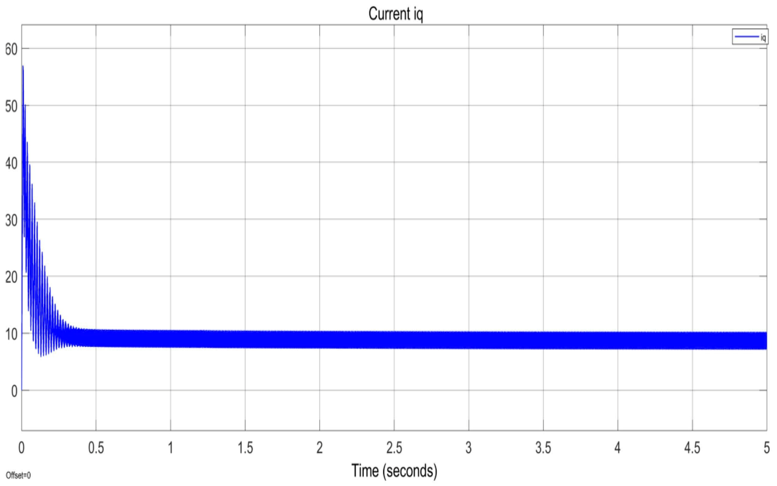
Figure 12.
The three ACs’ current response.
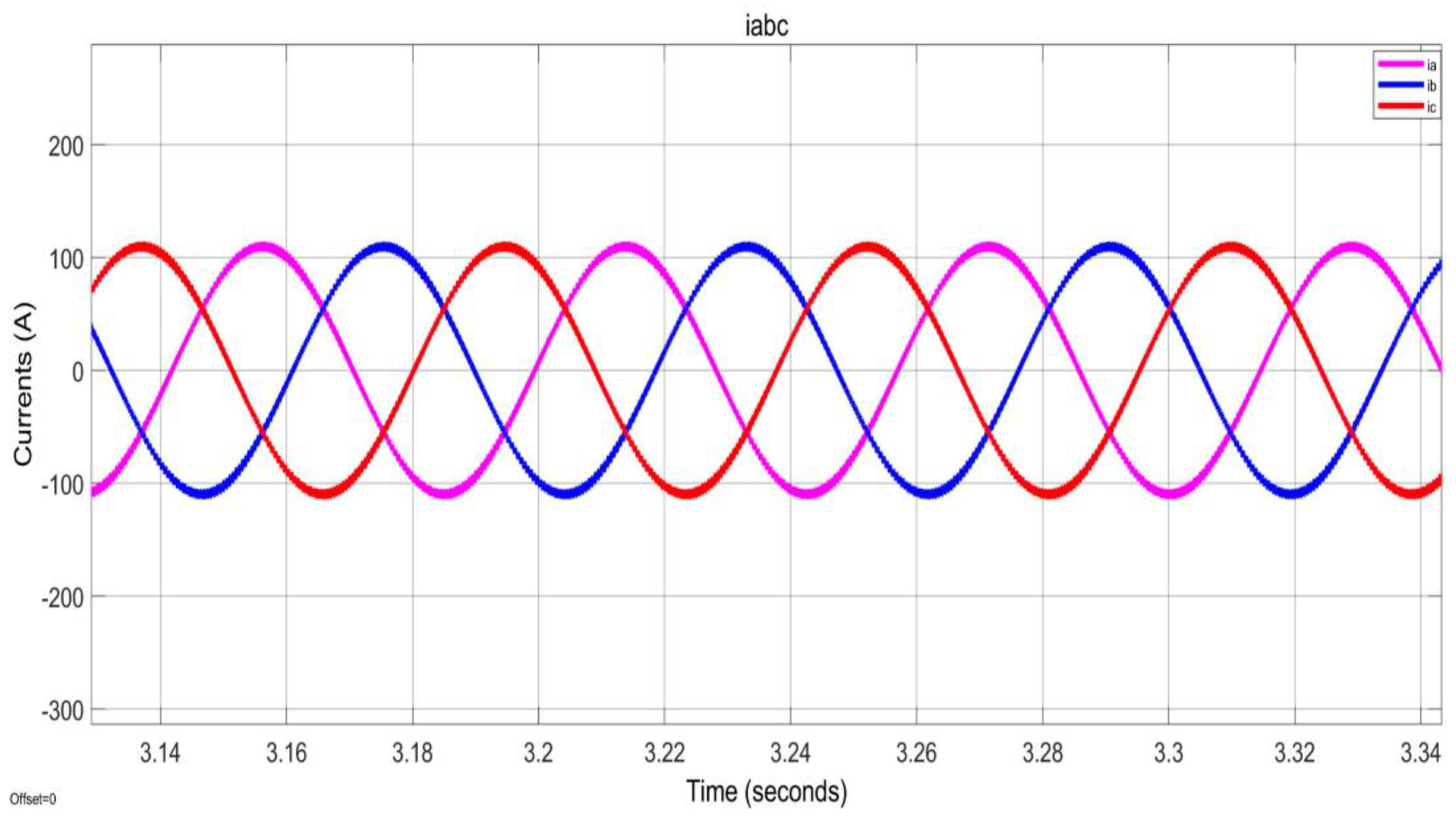
Figure 13.
The speed response.
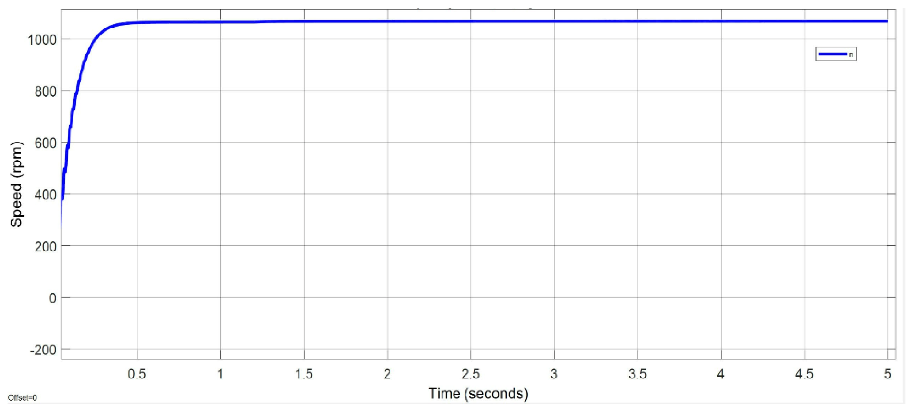
Figure 14.
The three-disc AFPMSM performance.
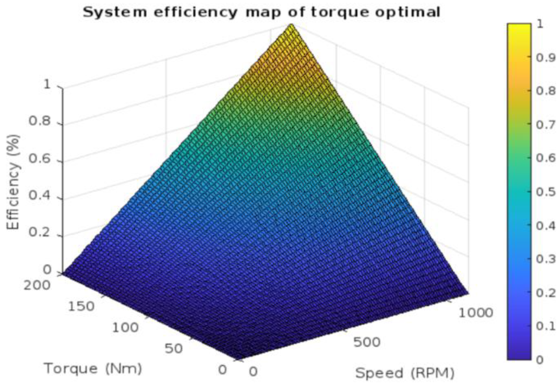
Figure 15.
The torque response.The torque (Tm) in Figure 15 demonstrates three distinct phases. In the initial phase (0-0.5 seconds), the torque rises to 300 Nm to overcome initial inertia, then quickly decreases due to the controller. During the transient phase (0.5-2 seconds), the torque gradually reduces with slight fluctuations as the system stabilises. In the stable phase (2-5 seconds), the torque stabilises at 10-20 Nm, indicating smooth and balanced motor operation. This confirms the controller's effectiveness in maintaining appropriate torque and preventing fluctuations.
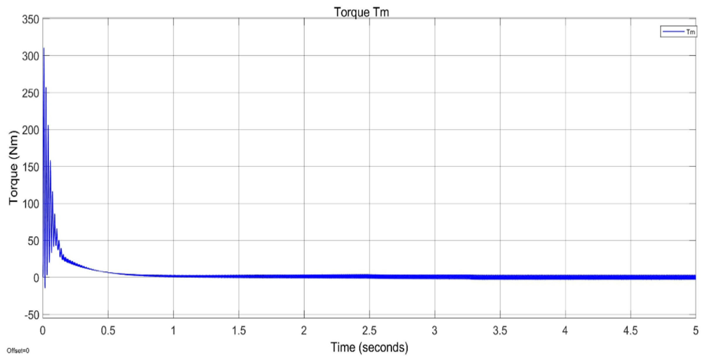
Figure 16.
The iq current response.
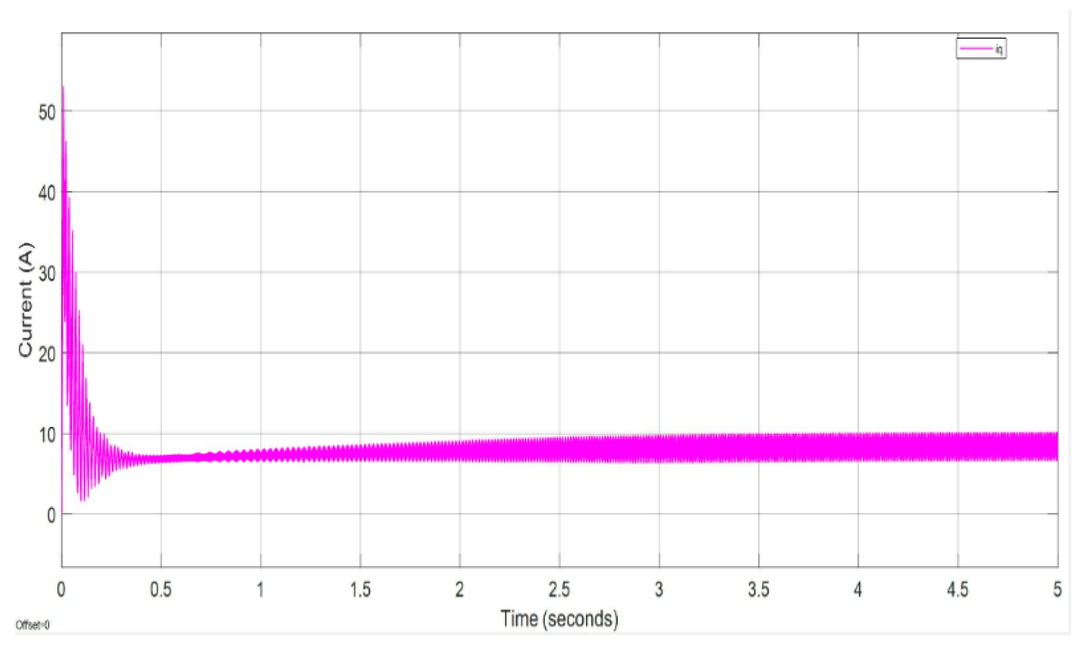
Figure 17.
The speed response.
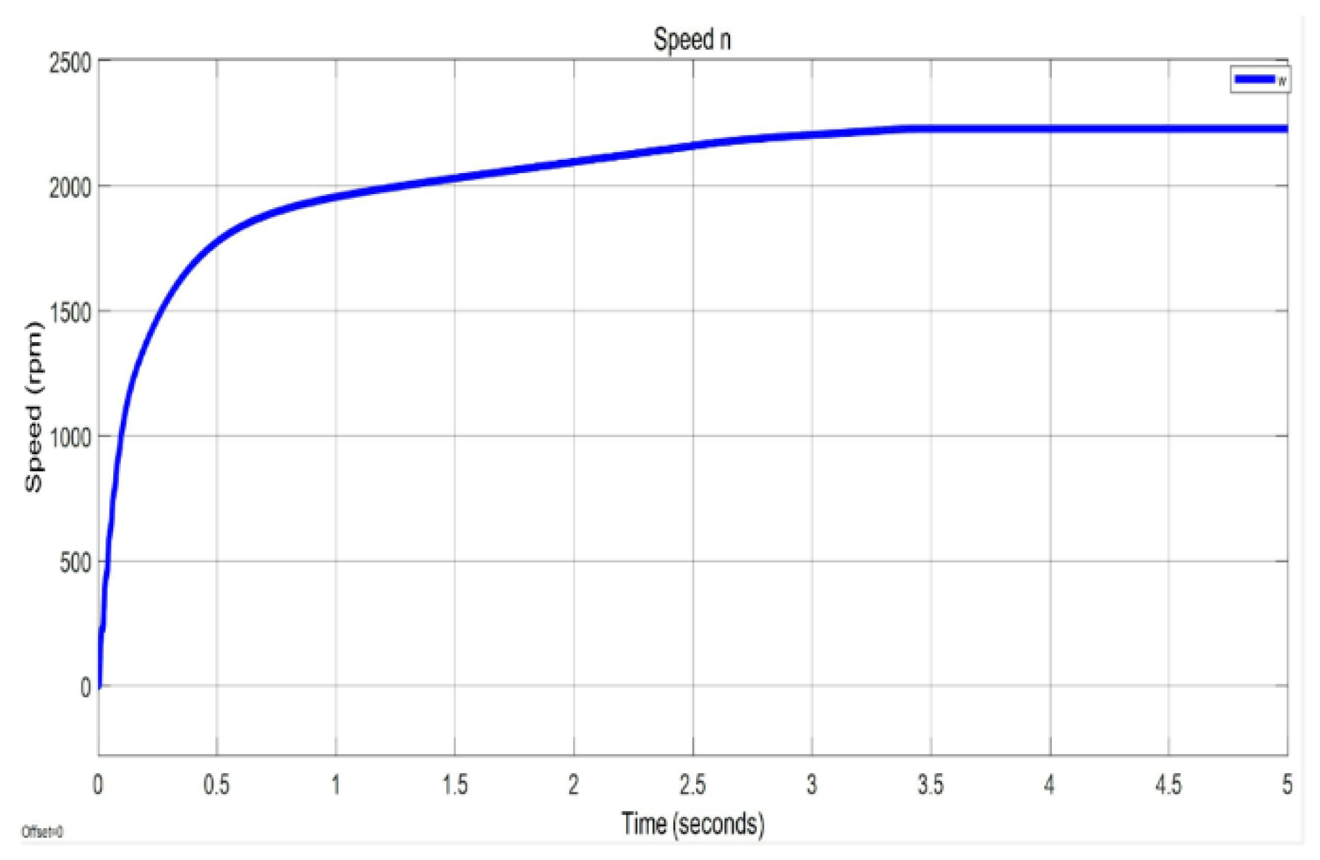
Figure 18.
The three-disc AFPMSM motor performance.
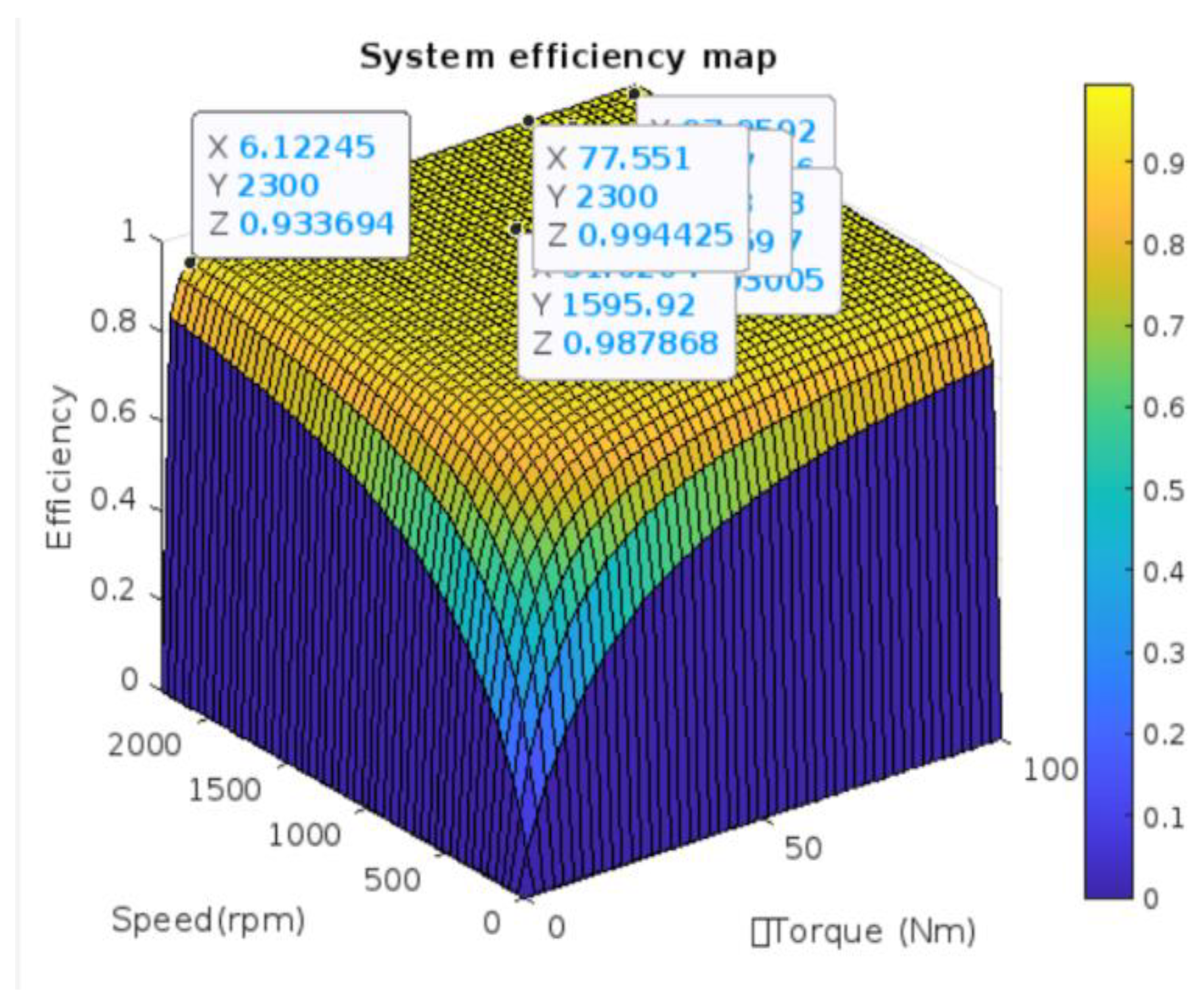

Table 1.
Optimised weights for the GA_BPANN algorithm.
| No | Layer | Weight Index | Optimized Weights |
| 1 | Input-Hidden 1 | 1 | 0.313 |
| 2 | Input-Hidden 1 | 2 | 0.095 |
| 3 | Input-Hidden 2 | 1 | 0.765 |
| 4 | Input-Hidden 2 | 4 | 0.378 |
| …. | ….. | …. | …. |
| 124 | Input-Hidden 2 | 24 | 0.464 |
Table 2.
Optimized biases for the GA_BPANN algorithm.
| No | Layer | BiasIndex | Optimized Bias |
| 1 | Input-Hidden 1 | 1 | -0.182 |
| 2 | Input-Hidden 1 | 2 | -0.427 |
| 3 | Input-Hidden 2 | 1 | -0.279 |
| 4 | Input-Hidden 2 | 4 | 0.052 |
| …. | ….. | …. | …. |
| 21 | Input-Hidden 2 | 3 | -0.188 |
Disclaimer/Publisher’s Note: The statements, opinions and data contained in all publications are solely those of the individual author(s) and contributor(s) and not of MDPI and/or the editor(s). MDPI and/or the editor(s) disclaim responsibility for any injury to people or property resulting from any ideas, methods, instructions or products referred to in the content. |
© 2025 by the authors. Licensee MDPI, Basel, Switzerland. This article is an open access article distributed under the terms and conditions of the Creative Commons Attribution (CC BY) license (http://creativecommons.org/licenses/by/4.0/).
Copyright: This open access article is published under a Creative Commons CC BY 4.0 license, which permit the free download, distribution, and reuse, provided that the author and preprint are cited in any reuse.


