

Submitted:
20 December 2023
Posted:
04 January 2024
You are already at the latest version
Abstract
This article describes the study and digital implementation of a system onboard a TMS 3208F28335 ® DSP for vector control of the bearing motor speed with 4 poles split winding with 250W of power. Smart techniques: ANFIS and Neural Networks were investigated and computationally implemented to evaluate the bearing motor performance under the following conditions: operating as an estimator of uncertain parameters and as a speed controller. Therefore, the MATLAB program and its toolbox were used for the simulations and the parameter adjustments involving the structure ANFIS (Adaptive-Network-Based Fuzzy Inference System) and simulations with the Neural Network. The simulated results showed a good performance for the two techniques applied differently: the estimator and a speed controller using both a model of the induction motor operating as a bearing motor. The experimental part for velocity vector control uses three control loops: current, radial position, and speed, where the configurations of the peripherals, that is, the interfaces or drivers for driving the bearing motor.
Keywords:
Bearingless
; DSP
; Induction motor
; Radial position control
1. Introduction
The first split-winding bearing motor was proposed by Salazar & Stephan [1]. Victor in [2] analyzed the feasibility of using a conventional induction machine as a split-winding bearingless motor. He performed position and current control of the machine; however, he observed that radial position control was not satisfactory for speeds below the rated limit. In recent years, [3] studied the replacement of PID controllers for radial position control with controllers based on fuzzy logic. Noting the strong nonlinear and parameter-varying characteristics of induction motor bearings, he analyzed the contribution of Fuzzy controllers on transient and permanent regime performance. In order to reduce the number of equipment needed for machine control, [4] optimized the structure of the motor bearing by proposing a new way to connect the coils in the machine stator. In [5], the machine’s performance operation with a conventional state estimator and a neural state estimator was compared.
Speed control operating with the bearing motor was studied by [6,7]. The Artificial Neural Networks (ANN) technique was chosen. The ANFIS technique was investigated and studied by [8,9,10]. The adaptive neuro-fuzzy in motor studied by [11,12]. The speed control operating with the bearing motor was evaluated by comparing the implementation of classic PI control with an artificial intelligence technique. Thus, the Artificial Neural Networks (ANN) technique was chosen to replace the classic PI control technique. The first step in implementing ANN was choosing the data set, the ANN input data are the mechanical speed and the mechanical speed error. The ANN output data is the torque current.
This work aimed to study and implement the artificial intelligence technique applied to vector speed control for the split wound type bearing motor based on the induction motor. The aim was to investigate and simulate the intelligent ANFIS techniques and Neural Networks to evaluate the performance of the motor-bearing in the following conditions: operating as an estimator and as a speed controller. The split winding motor-bearing, which was adopted in this work, was proposed by [13]. In the experimental part, the TMS3208F28335 DSP was used to integrate the control algorithm with the current, position, and speed interfaces, by composing a cascade system. The intelligent technique implemented was the Neural Network, which acted as a speed controller. The position and mechanical speed results were compared with the PI speed controller and the Neural Controller. The control algorithm implemented in the TMS320F28335 DSP was developed in ANSI C programming language. The motor-bearing system is located in the Computer and Automation Engineering Laboratory (LECA) at UFRN.
The article describes the implementation details of controllers that provide the opera- 49 tion of the bearing motor. The system is current, radial rotor position, and speed, which 50 operate in a cascade. Control loop implementations started with the loop from the in- 51 nermost (fastest) control to the outermost (slowest) loop, following the sequence: current 52 control, position control, and speed control. Speed and position controllers are responsible 53 for the generation of reference currents for current control.
2. Simulations of the Techniques of Artificial Intelligence
This section presents an introduction to vector modeling of the induction machine working as a bearing motor. The characteristics have detailed the design of the Neuro-Fuzzy Estimator and the Neural Controller. The results simulated showed in a different way a good performance for the two applied techniques: as an estimator and as a speed controller using, both of them are models of the induction motor operating as a bearing motor.
The evaluation of artificial intelligence techniques uses the diagram of blocks of Figure 1. The neural controller replaced the green block represented by the Proportional-Integral, and the estimator conventional represented by the orange block by ANFIS.
The block diagram in Figure 1 presents the system’s complete structure adopted in the computer simulation stage. The modeling described in the next section and the other topics will describe the main parts, requirements, and restrictions for the system to function as a bearing motor (blue block).
2.1. Three-Phase Induction Bearing Motor with Coil Divided
Proper operation of a bearingless machine requires control of the position, rotation, and torque of the rotor shaft. To achieve these forms of control is to know several parameters of the machine, such as: the number of poles, nominal rotation, nominal current, operating frequency, rotor inductances, stator inductances, mutual inductances between rotor and stator, rotor resistances and stator, and in real-time, with the use of sensors, the position and rotation of the rotor axis in relation to the stator, currents, magnetic fluxes and voltages [14].
Thus, Table 1 presents some parameters obtained through tests performed in the laboratory [2] and adopted in this work for the simulations and obtaining the results.
The machine’s structure adopted as a reference in this work has three phases, four poles, and utilizes the squirrel cage rotor; the coils are connected in series to form a phase group, and each phase group has two diametrically opposite coils, according to Figure 2. Figure 2 shows the distribution of the coils in the stator and the currents in each half group of the winding for the bearing motor used in the research. Figure 2 shows the stator winding distribution, where there is a 120o phase shift angle between each phase group axis. Figure 2 below describe the unbalance of the currents for the position control. In order to reduce the system’s complexity, it was considered that the rotor be centered for the simulations. Note that is the stator current, and represents the rotor current.
2.2. Tuning the Controller for Vector Control
The section describes the considerations adopted in the bearing motor for the computational simulations.
Field-oriented control has emerged as an essential contribution to the control of induction motor machines and continues to be discussed and developed in the literature [15]. This type of control enables a decoupling between torque and flux in the alternating current machine, making it similar to a direct current machine with independent excitation.
The velocity vector control shown in Figure 1 is composed basically of three Proportional-Integral type controllers, namely: Controller for the speed error, whose output is the reference electrical torque . In series with the speed controller, there is the current controller, the torque, which is responsible for generating the torque current reference -, lastly, the magnetizing current controller, which is responsible for generating the field current reference [15]. The rotor was centered on the project simplification for Proportional-Integral-Derivative (PID) controllers referring to the x and y positions. Figure 3 shows the various tunings carried out empirically for the mechanical speed control loop and, similarly, the tuning of the controllers of the other loops in order to find the best answer for the system according to Table 2.
2.3. Description of Artificial Intelligence Techniques Applied to the Bearing Motor
The implementation of artificial intelligence techniques took into account consideration some criteria for the simulation. Use Matlab ® for the implementation of the proposed system in Figure 1.
2.4. ANFIS Estimator
The conventional estimator adopted in the simulations was compared with the ANFIS estimator according to [16], and the training process using a 60-second training time interval, and variations of parameters were imposed considering the following criteria:
- Successive ascending and descending steps were applied between 0 and 2000rpm (reference speed ranges);
- Variation of rotor time constant (every 2 seconds, so random values ranging from % concerning the nominal value of the constant);
- Every 5 seconds, increasing and decreasing variations were applied load of N.m (load torque variation); This criterion was based in [15].
2.5. Neural Controller
The Neural Controller replaces the PI Speed controller in Figure 1. The design of the neural controller is described in [16], the data collection for training the neural network followed some criteria:
- The training process used a training time interval 60 seconds;
- Successive ascending and descending steps were applied between 600 and 1900 rpm (random variations of reference speeds);
3. Design and Analysis of the ANFIS System
The structures adopted in the Neuro-Fuzzy estimator were based on two estimators, one for estimating the magnetizing current and the other for estimating the rotor flux. The ANFIS 1 estimator uses the following inputs: the direct field current and the delayed magnetizing current, and as output, the magnetization current. The ANFIS 2 uses the following inputs: mechanical velocity quadrature current angular velocity as output estimated after discretization .
In order to find the best configuration, it was performed several training with different parameters to obtain better criteria for the simulations according to Table 4 and Table 5.
The criteria adopted in both estimators were 300 times for training and zero-tolerance error.
Figure 4 (A) illustrates the Fuzzy surface obtained as a result of quadrature and magnetization current training. It is deduced that the linear result obtained is due to the centered rotor. Figure 4 (B) illustrates the Fuzzy non-linear surface obtained due to speed training mechanics and quadrature current.
Figure 5 illustrate the behavior before and after training to adjust the memberships: and the curves [blue, green and red] represent the rules generated by ANFIS and {in1mf1, in1mf2 and in1mf3} are the memberships generated by ANFIS 1 and by ANFIS 2 are {in2mf1, in2mf2 and in2mf3}.
It is observed that after the end of the training, the pertinence functions of Figure 6 were adjusted for each input of estimator 1 of Figure 4 (A). With the result of the training of the ANFIS 2 estimator, the membership settings for the entries were obtained. Figure 6 illustrates the behavior before and after mechanical speed training.
Figure 6 (A) shows the cancellation of membership already in Figure 6 (B) there was no cancellation of membership, but a distribution of the same. These elimination and distribution results are pertinent to the Neuro-Fuzzy training.
3.1. Results of Simulations with the ANFIS Estimator
The simulations were run in the range of 0 to 20 seconds. The result shown in Figure 7 shows the mechanical speed of the motor simulated subject to the following reference changes 680, 1800, and 900 rpm, and then a perturbation at the instant 10 seconds is applied. The disturbance was an application of a load torque with a nominal value to N.m.
The following result shows the performance of the controller error speed referring to the conventional estimator model and the estimator ANFIS, Figure 8.
Figure 9 shows the behavior of the electrical torque in the conditions imposed in the simulation with conventional estimators and with the Neuro-Fuzzy estimator.
Figure 10 illustrates the PI controller error signal for electrical torque and identifies the controller error behavior for each simulated estimator.
Figure 11 shows the behavior of the angular position with a zoom in an operating range of 0 to s. It is observed in this result from the timing for the estimators.
4. Neural Controller Design and Analysis
The neural structure used the three inputs: mechanical speed - wmec(k), error(k) current error; and the previous error (k-1) and as an output torque reference () for the torque controller. The process of training was carried out in offline mode, and its collection used points for the input and output pairs, with a mechanical speed variation of 600 to 2000 rpm, randomly. Table 6 presents the parameters structures of the Neural Network, in which the convergence of the training process occurred in 841 epochs.
The topology in Table 6 was chosen after several performance tests with a different number of layers and neurons per layer, the algorithm of chosen training was the Levenberg-Marquardt. Figure 12 shows the error curve obtained with network training neural.
Figure 13 shows the performance of training, validation, and assessed tests resulting from the training.
Figure 13 shows the R parameter at the top. This parameter indicates the relationship between the output and the target, varying between 0 and 1. The more close to 1, the better the prediction. After training, the weights were adjusted, and the neural network simulation replaced the PI control in Figure 1.
4.1. Results Neural Network Simulations
The simulations were run from 0 to 10 seconds. The result is shown in Figure 14 shows the mechanical speed of the motor simulated subject to the following reference changes: 1200, 1800, and 1500 rpm.
The following result shows the performance of the controller error speed referring to the implemented controllers according to Figure 15.
Figure 16 (A) illustrates the error signal of the neural controller and PI for the electrical torque and in (B) the neural controller error signal and PI for the current of magnetization, showing that in both Figure 16 (A) and (B) the error has been canceled, except when the mechanical speed reference changed.
Figure 17 shows the behavior of the angular position with a zoom-in operating range from 0 to s. It is observed in this result that the timing for the estimators.
5. Experimental Arrangement
According to [17], the kVA three-phase induction motor received modifications to operate a bearing motor, for example: the configuration of the double star coils and the removal of one of the bearings from one end of the rotor shaft. This last modification caused problems in the work of [2], according to which the problem of eccentricities of the motor-bearing shaft caused when there is displacement of the rotor made it difficult to adjust the position controller gains. The orbits were designed by rotating the shaft manually and then translating it through the periphery of the air gap. According to [2], after installing the self-aligning bearing, the shaft started to produce several orbits when peripherally displaced. Figure 18 shows three possible orbits designed by moving the shaft peripherally in the housing box of the top bearing.
After replacing DSP 2812 with DSP 28335, the empirical tuning of Position PD controller has become a difficult task. In order to solve the problem of the eccentricity of the rotor shaft, the induction motor was taken to the Laboratory of Mechanics and Turning, which is located on the Parnamirim campus of the Federal Institute of Education, Science and Technology of Rio Grande do Norte (IFRN). In order to correct the imbalance, the induction motor was disassembled, and the rotor shaft composed of the bearings and the disc was positioned in the lathe to perform roughing on the disc. In order to increase accuracy, it was used the clock in thinning.
However, the eccentricity problem persisted, decreasing only the number of orbits. With the correction of the unbalance of the shaft in the lathe, the number of orbits went from three to two. This phenomenon made it difficult to tune in to the position controller. The solution found was the replacement of the conventional induction motor modified from the work of [2] by the prototype of the bearing motor used in the work of [13], which was located in the Laboratory of Computer Engineering and Automation (LECA) at UFRN.
According to [13], the bearing motor is a conventional induction machine adapted to operate without its mechanical bearings, having its radial positioning controlled by magnetic fields. The data used as parameters for the control of the machine were from the Table 7.
After the replacement of the motor, it was necessary to configure the connection of the electric motor. For this, the coils and they were respective phases, because, according to [13], the stator coils suffered some changes, they were divided in half as a strategy to carry out of control. In Figure 19, the location and identification of the groups of coils.
Based on the experiments, Figure 20 shows the arrangement of connections of these windings for operation as a bearing-less machine of the split coiled.
In order to facilitate the identification of phases and coil groups for name the X and Y axes for position control, it was necessary to perform two experiments with the aid of a compass. It is possible to check the compass orientation indicating the Y direction, shown in the Figure 21.
The result of Figure 21 identified each coil group according to the sequence of Figure 20. For this, each group of coils was excited with continuous tensions.
However, it was necessary to adjust the position and speed of the related peripheral to allow effective control under the conditions imposed on the bearing motor. These modifications are presented in the following sections.
5.1. Radial Position Sensors
According to [18], the radial position control for a bearing motor consists of making the rotor float, that is, without mechanical contact with the stator. Further details on position sensors can be found in [14].
Figure 22 shows the electronic circuit used with the AEC 5505-04 sensor.
Figure 23 shows the radial displacement for two situations. The first situation presents a more extensive area referring to the maximum limit of the displacement between the axes, as well as signals reaped on the X and Y axes, while the second behavior presents the maximum limit of the desired radial offset for position control, both displacements were performed manually.
The solution in the second radial displacement was possible by attenuating the signals from the X and Y sensors with the addition of two resistors before the operational amplifiers present in the diagram in Figure 22. The resistors were positioned at the input of the X and Y axis position signals. However, another problem persisted, the calibration of the sensors according to Figure 24.
Figure 24 (A) shows a distorted figure, justified by the presence of the signal. Figure 24 (B) where there is reaping in the Y-axis signal represented by the color yellow. This problem can occur in the axes signals X and Y. In this case, the correction of this problem is done by adjusting the offsets. To do this, you must make the Y-axis signal behavior do not show any signs of mowing. When the Y-axis sign is approximated the sign of the X-axis, the result of adjusting the offsets results in the Figure 25. The behavior of the signals equivalent to the X and Y axes must be adjusted until you get the behavior of Figure 25.
After replacing the bearing motor, the problem of rotor eccentricity, as can be seen in Figure 26.
Another advantage identified in replacing the bearing motor was the increase in the air gap, which went from mm to mm, which allows a larger range for empirical tuning of position control.
5.2. Rotation Sensors
According to [14], a rotating machine, when subjected to a torque on the shaft, in addition to needing more current in the coils, it also undergoes a variation in rotation. Thus, it is essential to know the rotation in real-time and the currents in the coils to implement a control machine rotation. In order to measure the rotation on the axis of the bearing motor, an encoder consisting of a disc was adopted uniformly perforated, a receiving transistor, and a light-transmitting LED structured infrared. However, in the tests, it was found that the circuit previously used by [18] had noise problems and sometimes loss of pulses, causing loss of measured speed value or measurement error.
5.3. Complete System
In [2], it is briefly explained that alternating current, from source to the power of the stator coils, is transformed into current continuous in the converter and again transformed into alternating in the inverter frequency. The modulation of current in frequency inverters is performed through signals from the DSP control system. The current produced generates both torque and radial forces from rotor positioning. The mechatronic system, including each of the elements composed by the system and other components such as interfaces, sensors, and command devices, can be seen in Figure 27.
This section dealt with the details of the changes made to the interfaces with the bearing motor. Basically, there were changes in the position and velocity sensors, and after adjustments, the system was able to implement the control structure and obtain the experimental results, exposed in the following section.
6. Control Structure in Bearing Motor Cascade
The following text describes the implementation details of the controllers that provide the operation of the bearing motor. The complete system is composed of the current, position, and speed controllers, which operate in a cascade. The implementations of the control loops were started with the loop. from the innermost (fast) control to the outermost (slower) loop, following the sequence: current control, position control, and speed control. The speed and position controllers generate reference currents for current control. So after the action of controlling the currents of each coil is applied to the motor-bearing windings, the scalar PWM outputs are generated for the two three-phase inverters.
6.1. Current Control
The high performance in the drive of electrical machines depends mainly of the control technology implemented, being employed control techniques with current feedback in all applications. These techniques require fast response, high accuracy, and a performance high level. Current sensors, as well as other sensors used in the machine are important for the control in real-time, can impose changes necessary for the correct functioning of the machine, [18]. Current controllers must be of the Proportional-Integrative type (PI), they are simple to implement and manage to eliminate errors in regime [2]. The structure used for the control of current in this work was based on the module implemented by Texas (C28x Solar Library, [19]). This module has the following characteristics: programmed output saturation; adjustment of independent weights on actions proportional and derivative; reset in anti-windup integrator; and a filter Programmable for a derivative action. However, the derivative action was annulled for this control, acting only on the proportional and integral actions.
The equation of the PID controller before saturation is described as equation (1):
Each term can be written as follows: Proportional term:
Integral term:
Derivative term with filter:
Finally, the output with saturation is defined:
In these, a reference; a control variable; term derivative; integrative term; proportional term; , the weight referring to reference; the proportional gain; the derivative gain; the derivative filter coefficient 1; the coefficient of derivative filter 2; , the maximum saturation limit; , minimum saturation limit.
7. Position control
For the implementation of position control, you must take into consideration the study by [13,20], ), [15], and [2]. These works demonstrate the rotor positioning model and identify that the model is unstable in open mesh due to the presence of two poles, one in each semi-plane. The solution found for the system to become stable was the implementation of the Proportional-Derivative (PD) controller, which adds a zero is positioned to attract the place of the closed-loop roots to the left half-plane. The control law implemented for position control was based on [2].
8. Radial Forces Generation
Signals , come from the position control. Then, they undergo a rotational transformation to the static orthogonal system and transform into , and Lastly there is a coordinate transformation biphasic to triphasic, resulting in , , observed, that the controller signals , , after the transformations, they have added to the phase current references or subtracted in each half group of coils from phases A, B, and C, respectively, to control the restoring forces of the rotor position, (Equation 6).
In these equations, , , and , are the imposed phase reference currents and , , , , , , are the reference currents for position control. Due to the nonlinearity of the system, the tuning of the controllers becomes difficult to obtain; however, the parameters of the controllers were determined empirically.
8.1. Vector Speed Control
The speed controller used is a PI (Proportional-Integral) with anti-windup, the feature that interrupts the integration process when output has already reached a maximum saturation value [21]. For the implementation of velocity vector control, initially, the structure of control of Figure 28 using flow estimator. The big advantage of this structure using this estimator is the presence of a small number of equations, minimizing the computational effort [22].
The flux estimator used in [22] is given by:
In this, , the estimated flux; the mutual inductance ; the field current. Equation (7) is calculated from the field current and the inductance mutual . Thus, the calculation of the torque current () obtained from the equation (8) .
Here, reference torque; the inductance of the rotor; , the flux reference rotor; and P, the number of pole pairs. However, this structure does not was chosen for the following reasons: the difficulty of tuning in empirically the control loops, which consumed more time, and the fact of not having the necessary machine parameters to be used in equations (7) and (8).
However, it was thought to obtain the parameters from laboratory tests, which were discarded due to the following disadvantages: A delay in the digital implementation of the control structure may be a physical problem with the engine, generating more time for its solution or maintenance. Therefore, the control system implemented for the vector control of speed of Figure 29 took into account two simplifications: impose a reference field current to not implement flow control and eliminate the current torque calculation, causing the control output go straight into Park, and Clarke’s inverse transforms as torque investigation will not be taken into account. The structure of Figure 29 has three loops, the outermost being the Proportional-integral (PI) speed control, which controls the rotor shaft speed from the sensed feedback and whose output is the torque current the Proportional-Derivative Integral (PID) controller for the positions referring to the x and y coordinates of the rotor, since, in practice, the added integral action should decrease the regime error. Position control is classified as a regulator, unlike the current control system, which is classified as a follower [20]. Therefore, the last control loop is the current one, the innermost one, and quick response, with PI controllers for the six stator windings.
This section allowed us to deduce the simplified control diagram and function for implementing velocity vector control. The choice is to discuss the current position and speed controllers that helped to define the chosen strategy. The next section presents the experimental results of each step of the cascade control loop of the bearing motor.
9. Experimental Results
The experimental results were obtained with the digital implementation of the control system in the motor-bearing using the DSP 28335. An artificial intelligence approach was implemented in the results of speed vector control. In addition, a comparison of the Proportional-integral velocity vector control with the neural controller.
9.1. Stator Currents
To validate the digital implementation of the current control, some experiments with the centralized rotor with the current PI control. The procedure followed the block diagram sequence in Figure 30, based on the block structure of Figure 29.
Some experiments were carried out to validate the performance of the current PI controller. The first one was the response to several steps in the reference imposed on coil according to Figure 31. The PI controller parameters of current and were empirically adjusted for the obtaining the results and other experiments.
For this experiment, continuous currents were imposed with reference change over 1s interval of execution. Another result obtained was considering the current of sinusoidal reference and alternating it at a frequency of 60Hz and with an amplitude equal to according to Figure 32.
The experiments were carried out by changing the frequency and the reference range. Figure 33 shows the experiment obtained when the engine works at 15Hz frequency with equal reference amplitude (Imax) to A.
To evaluate the behavior of the bearingless machine operating as a induction and activating the six coils, it was necessary to perform two procedures: 1) fix the rotor shaft in the center so that it does not influence the dynamics of the experiment and operate with the rotor centered; 2) generate six streams of 120o offset references to generate the rotating field equation (9).
9.2. Radial Rotor Position
The results presented below were obtained with the control Proportional-Derivative-Integrative (PID) from some experiments. The results used the block diagram strategy of Figure 37 based on Figure 29.
After some empirical adjustments on the controller parameters, the gains obtained were: , , , , , . An experiment was carried out with the controls of position acting independently, evaluating the behaviors of the X- axis and Y-axis. Figure 38 shows the response to a step variation for the position control along the X-axis.
Figure 39 shows the response to a step change for the control of position along the Y axis.
The results were collected in a steady state. the experiment performed operated at the frequency of 60Hz according to Figure 40. The spot in the center of the figures represents the positions that the rotor has assumed in a given moment: the oscilloscope is in trace persistence mode.
The motor operation was verified at frequencies of 15Hz, 30Hz, and 45Hz with the same tuning parameters to check the position control performance. Figure 41, Figure 42 and Figure 43 show the results.
The result of Figure 43 demonstrates the success of the rotor positioning, as it remained to levitate the rotor without touching the lateral limits.
Figure 44 and Figure 45 represent the plots of the signals of both position sensors operating at the frequency of 60 Hz. In these results, the data were obtained without the parameterization performed for millimeters versus the amount of samples allowed by the DSP buffer.
In order to illustrate the dynamics of cascading control, the results considered an equal time window for the position controllers and the current operating at a frequency of 60Hz. Figure 46, Figure 47 and Figure 48 show the results of the cascading current and position controllers accordingly with the block diagram of the Figure 37. The graphic of Figure 46 (A) shows the reference currents, that is, the imposed currents , , and for control of position, collected at an interval of seconds.
The graph in Figure 46 (B), identified by the subtitles Ref1, Ref2 and Ref3, represents the composition of the reference currents , , and with the signs from position controllers , , and . Finally, the graph (C) represents the equivalent sensed currents in each phase. Figure 47 and Figure 48 show the responses of the X and Y positions with their respective reading errors associated and control signals. There is a small change in the behavior of the sensed currents in Figure 46 at times close to seconds, for example. This change is due to the control adjustment of the position of Figure 47 and Figure 48 and observed in the control signals for the X and Y positions.
9.3. Speed Control
The speed control operating with the bearing motor was evaluated by comparing the implementation of classic PI control with an artificial intelligence technique. The technique chosen was the Artificial Neural Networks (RNA) to replace the classic PI control. The ANFIS technique was investigated. However, due to the computational cost of its implementation, it was discarded.
The first step in implementing the ANN was choosing the data set for training and validation. The inputs are the mechanical speed the mechanical speed error () and the output is the current (). The input and output data pairs are used to adjust the internal parameters of ANN according to [23]. The RNA was configured fully connected. The database was developed with 20200 samples, of which 70% of the data were used in training and 30% for validation. The training process was carried out in offline mode, and its collection used the input data with a variety of mechanical speeds randomly from 1% to 5% overrated speed 1800 rpm. Table 8 presents the structural parameters of the Neural Network, in which the convergence of the training process occurred in 104 epochs.
The training algorithm chosen was the Levenberg-Marquardt, used in the Matlab toolbox for better accuracy; the topology Table 8 was chosen after several performance tests with a different number of layers and neurons per layer. The final choice led to considering the digital implementation and evaluating the processing time of the DSP. The more layers and neurons, the longer the processing time increases. Thus, the implemented structure analyzed the computational cost. Figure 49 shows the training performances, validation, and the evaluated test resulting from the training.
Figure 49 shows the R parameter at the top. This parameter indicates the relationship between the output and target, varying between 0 and 1. The more close to 1, the better the prediction. Figure 50 shows the training graph with the Mean Square Error (MSE).
After training, the weights listed in [16] and carried out two experiments to evaluate the functioning of the bearing motor operating with PI speed control with gains and and with the neural structure. The two case studies used the same RNA structure implemented.
9.3.1. Case Study I—Ramp
The first experiment presents the system’s behavior when being powered from rest to a rated speed of 1800 rpm. Figure 51 shows the mechanical velocity dynamics and the X and Y positions, respectively, in the function of time operating with the two controllers.
The legends of the graphs in the experiments present, respectively, the references and the responses with the PI control and with control identified by the colors green, blue, and red. Figure 52 shows the control signal behavior for the implemented controllers.
Figure 52 shows that the control signals are limited due to the motor constraints on the amplitude of A, that is, a constraint on the speed control signal for bearing motor operation.
9.3.2. Case Study II - Step Variation
The second experiment presents the system behavior operating at the nominal speed of 1800 rpm with a variation of 5%, that is, operating at 1710 rpm and 1890 rpm. Figure 53 shows the behavior of the mechanical speed and the X and Y positions referring to the rotor position.
In this case, the presence of overshoots in the performance of the The PI controller was identified with dashed circles, which did not occur with the neural controller. This behavior can be seen in Figure 53 because there were higher amplitudes in the PI control signal compared to the neural control. Despite the variations of the control signal in Figure 54, it can be seen that the position control performed well because the X and Y signs did not suffer variation.
Figure 55 shows the errors of the controllers being acted on by the PI and neural controllers. There is also a difference in amplitude between the controllers due to the effect shown in Figure 53; the responses are also different.
Thus, even with variations or changes in references in the speed control, Figure 56 shows the dispersion of signals concentrated, as these variations did not disturb the position control.
A model DT- digital tachometer was used to validate and check the mechanical speed of the rotor operating at 1800 RPM and using the PI and neural controllers. Figure 57 shows the mechanical speed results under regime permanent in (A) working with the PI controller and (B) with the controller neural.
10. Conclusions
The purpose of this article was to present the study and implementation of artificial intelligence techniques for motor-bearing speed control with a split coil. ANFIS Smart Techniques and Neural Networks were investigated and computationally implemented for the evaluation of the motor-bearing performance. The simulated results showed a good performance for the two techniques: as an estimator and as speed controller, using both an induction motor model operating as a bearing motor. The experimental implementation required adjustments in the interfaces of position, in the speed sensor and in the replacement of the DSP TMS by the DSP TMS , moving from fixed-point floating-point implementation. With the implementation of the motor-bearing system and the analysis of obtained results, some conclusions were possible: - the use of DSP 28335 helped in the implementation of the cascade control; - the tuning of the current, position, and speed controller, in the experimental results implemented in the DSP , was carried out empirically through the trial and error method, whose adjustment is difficult and laborious; - current control results were investigated with DC and AC currents, validating the controller tuning in the bearing motor; - position control result has been implemented and tuned to the frequency of 60Hz, but it presented best results at the frequencies of 15Hz, 30Hz and 45Hz; - the speed control operating conditions were synchronized with the position control, so the motor-bearing system operated properly with current control; - the operation of cascaded meshes requires a synchronism between the position control and the speed control because, if it does not occur, the controllers will not achieve stabilization; - the speed PI controller had overshoots, and the neural controller system did not present them, demonstrating the ability to learning and generalization of Neural Networks.
Author Contributions
J. R. D. N., J. S. B. L. and A. O. S. conceived and designed the study; J. S. B. L. and D. A. D. M. F. , methodology ; J. R. D. N. and D. A. D. M. F. performed the simulations and experiments; E. R. L. V., A. R. G. G., J. M. d. S. F. and A. O. S. reviewed the manuscript and provided valuable suggestions; E. R. L. V., J. S. B. L., D. A. D. M. F. and A. R. G. G. wrote the paper; supervision, A. O. S. and J. M. d. S. F.
Funding
This research was funded in part by the Coordenação de Aperfeiçoamento de Pessoal de Nível Superior—Brasil (CAPES)—Finance Code 001 and Conselho Nacional de Desenvolvimento Científico e Tecnológico (CNPq).
Conflicts of Interest
The authors declare no conflicts of interest.
Abbreviations
The following abbreviations are used in this manuscript:
| PWM | Pulse-Width Modulation |
| DSP | Digital Signal Processor |
| PI | Proportional Integral |
| PD | Proportional-Derivative |
| PID | Proportional Derivative Integral |
| MSE | Mean Square Error |
| AEC 5505-04 | Sensors |
| DC | Direct Current |
References
- Salazar, A. O. ; Stephan, R. M. A bearingless method for induction machines. IEEE Transactions on Magnetics 1993, 29(6), 2965–2967. [CrossRef]
- Victor, V. F. ; Quintaes, F. O. ; Lopes, J. S. B. ; Junior, L. d. S. ; Lock, A. S. ; Salazar, A. O. Analysis and study of a bearingless AC motor type divided winding, based on a conventional squirrel cage induction motor. IEEE Transactions on Magnetics. 2012, 48(1), 3571–3574. [CrossRef]
- Nunes, E. A. D. F. ; Salazar, A. O. ; Villarreal, E. R. L. ; Souza, F. E. C. ; Dos Santos Júnior, L. P. ; Lopes, J. S. B. ; Luque, J. C. C. Proposal of a fuzzy controller for radial position in a bearingless induction motor. IEEE Access. 2019, 7, 114808–114816. [CrossRef]
- Carvalho Souza, F. E. ; Silva, W.; Ortiz Salazar, A. ; Paiva, J.; Moura, D.; Villarreal, E.R.L. A Novel Driving Scheme for Three-Phase Bearingless Induction Machine with Split Winding. Energies. 2021, 14 (4930), 1–15. https://doi.org/10.3390/en14164930. [CrossRef]
- Teixeira, R.d.A.; da Silva, W.L.A.; Amaral, A.E.S.; Rodrigues, W.M.; Salazar, A.O.; Villarreal, E.R.L. Application of Active Disturbance Rejection in a Bearingless Machine with Split-Winding. Energies. 2023, 16 (7), 3100, 1–16. [CrossRef]
- Buro, N. G. Magnetic bearings and non-stationary dynamics of rotors. Forth International Symposium on Magnectic Bearings, 1994, ETH Zurich, Anais ETH Zurich, 1994.
- Bu, W. ; Li, Z. ; Wang, X. ; Li, X. A control method of bearingless induction motor based on neural network. 2015 IEEE International Conference on Information and Automation, 2015, pp. 2252–2257.
- Depari, A. ; Flammini, A. ; Marioli, D. ; Taroni, A. Application of an ANFIS Algorithm to Sensor Data Processing. IEEE Transactions on Instrumentation and Measurement. 2007, 56(1), 75–79. [CrossRef]
- Ding, W. ; Liang, D. Modeling of a 6/4 Switched Reluctance Motor Using Adaptive Neural Fuzzy Inference System. IEEE Transactions on Magnetics. 2008, 44(7), 1796–1804.
- Zhi-xiang, H. ; He-qing, L. Nonlinear system identification based on adaptive neural fuzzy inference system. International Conference on Communications, Circuits and Systems. Proceedings Guilin, 2006.
- Vasudevn M., Arumugam, R., Paramasivam, S., Adaptive neuro-fuzzy inference system modeling of an induction motor. International Conference on Power Electronics and Drive Systems, 5, Singapore. 2003. Anais… Singapore, 2003.
- Wang, Z. ; Liu, X. X. Nonlinear Internal Model Control for Bearingless Induction Motor Based on Neural Network Inversion. Acta Automatica Sinica. 2013, 39(4), 433–439.
- Ferreira, J. M. S. Proposal for a three-phase induction machine without bearing with split coil. PPGEEC-UFRN, Natal, RN, Brazil, 2002.
- Souza Filho, J. C. ; Santos Junior, L. P. ; Lopes, J. S. B. ; Victor, V. F. ; Salazar, A. O. Sensores e Interfaces com Aplicações em Motor Mancal. IEEE/IAS International Conference on Industry Applications, Induscon 2012, Fortaleza, CE, Brazil, 2012.
- Paiva, J. A. Speed vector control of an induction machine without three-phase bearings with split winding using neural estimation flux. Thesis PPGEEC-UFRN, Natal, RN, Brazil 2007.
- Lopes, J. S. B. Study and Implementation of Technique of Artificial Intelligence for the control of Speed of the Engine-Bearing with Winding Split using DSP TMS3208F28335. Thesis PPGEEC-UFRN, Natal, RN, Brazil, 2016.
- Lopes, J. S. B. ; Salazar, A. O. Approach the Rotor Flux Estimation of a Bearingless Motor using a Structure Adaptive Hybrid Neuro-Fuzzy. The 19th World Congress of the International Federation of Automatic Control - IFAC, Cape Town, South Africa - 24-29 August, 2014.
- Souza Filho, J. C. Sensores e interfaces com aplicações em motor mancal. Dissertação de Mestrado - Programa de Pós-Graduação em Engenharia Elétrica e de Computação, Universidade Federal do Rio Grande do Norte, Natal, RN, Brazil, 2011.
- C28x Solar Library: module user’s guide. Dallas, Texas: Texas Instruments, v.12, 2014.
- Castro, F. E. F. Three phase induction bearingless motor with divided winding: Optimization of the radial positioning system. PPGEEC-UFRN, Natal, RN, Brazil, 2004, pp. 105.
- Gomes, R. R. Bearing motor with control implemented in a DSP. Master’s degree, UFRJ, Rio de Janeiro, RJ, Brazil, 2007.
- Silva, P. V. Electromagnetic Frequency Regulator applied in the wind generator speed control. Thesis PPGEEC-UFRN , Natal, RN, Brazil, 2015.
- Santos, T. H. D. Estimador neural da velocidade do mit acionado por um driver com controle vetorial orientado pelo fluxo do estator. XII Simpósio Brasileiro de Automação Inteligente (SBAI), Natal, RN, Brazil, 2015.
Figure 1.
Block diagram of the proposed simulated system.
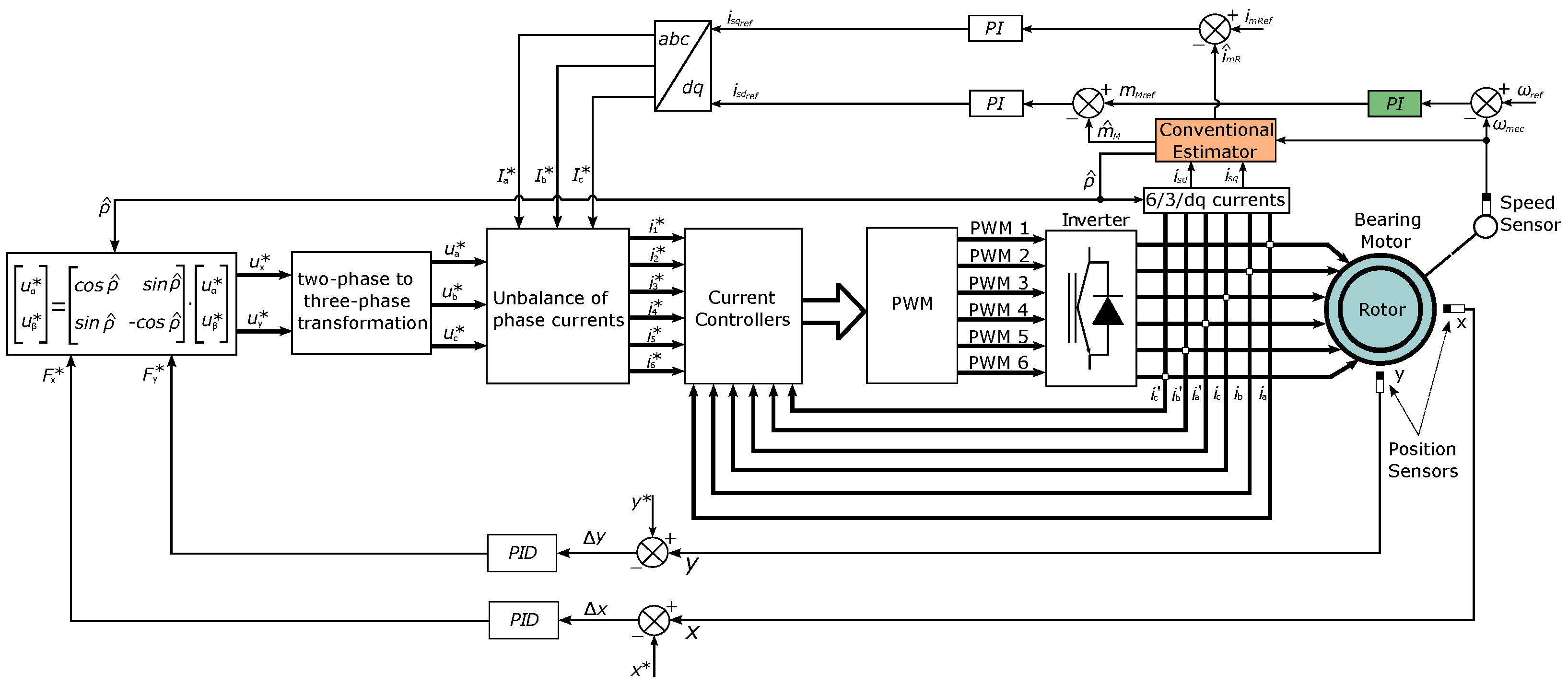
Figure 2.
Stator coil layout.
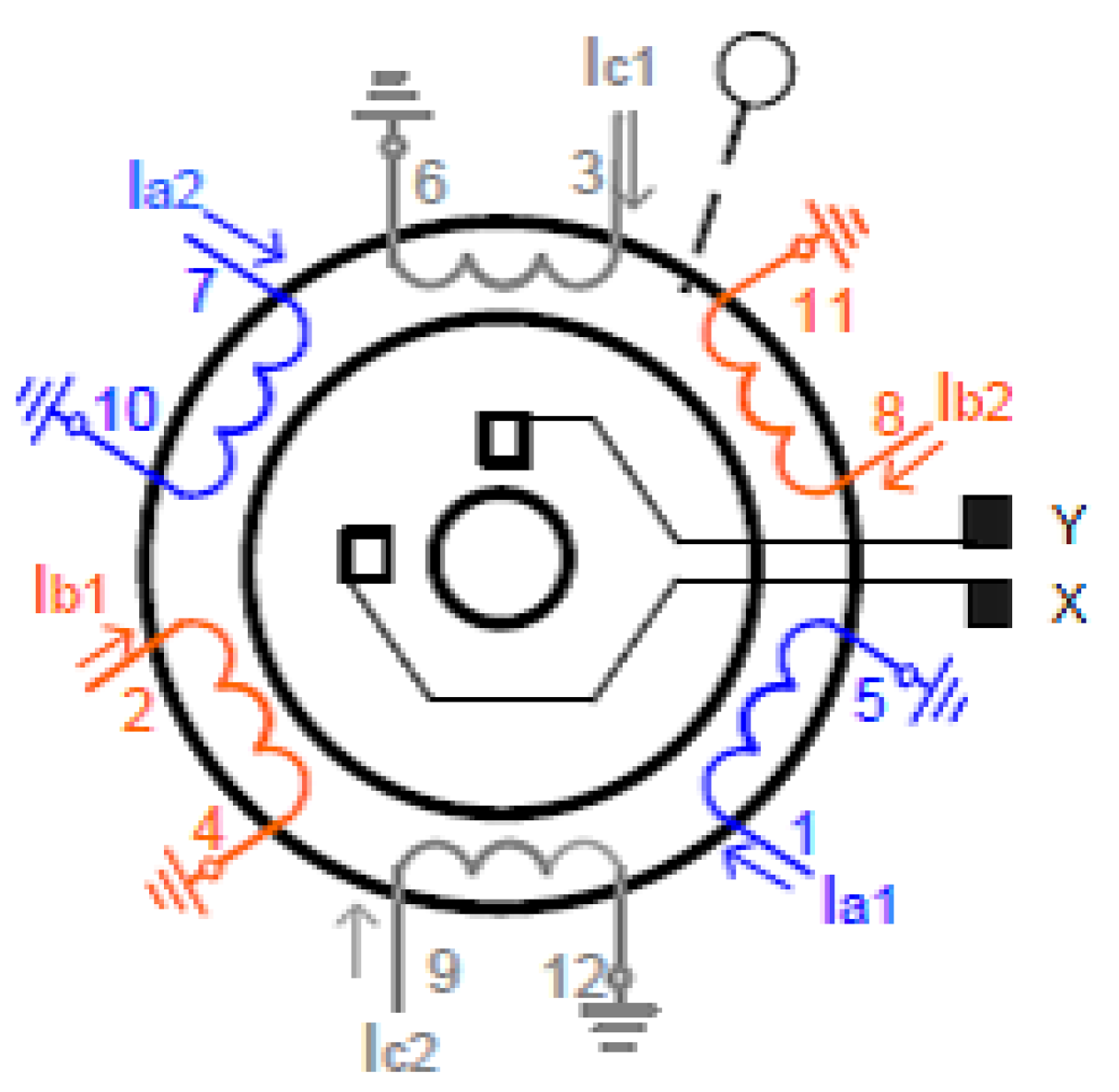
Figure 3.
Block diagram of the proposed simulated system.
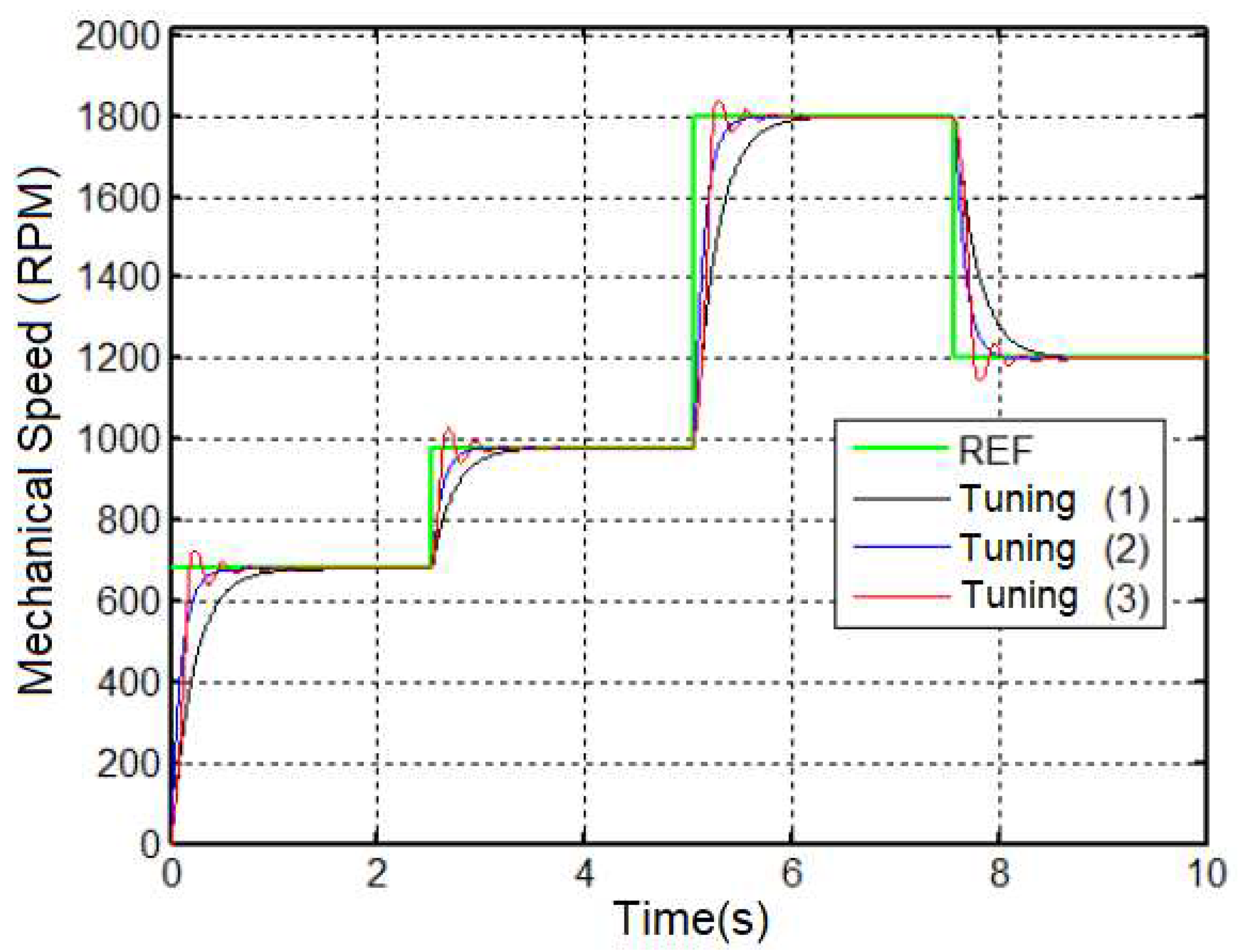
Figure 4.
(A) - Fuzzy Sugeno Surface - ANFIS 1 and (B) - ANFIS 2.
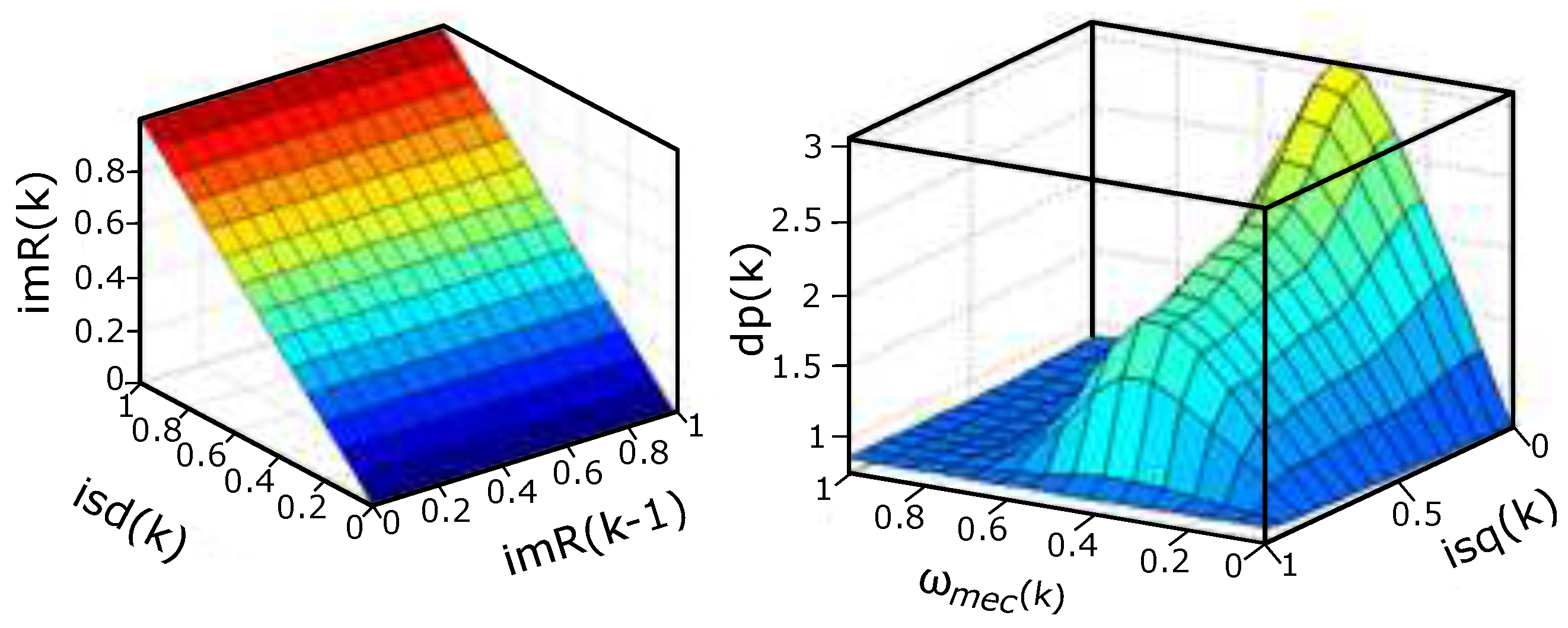
Figure 5.
Pertinences before training and after (A) – (B) .
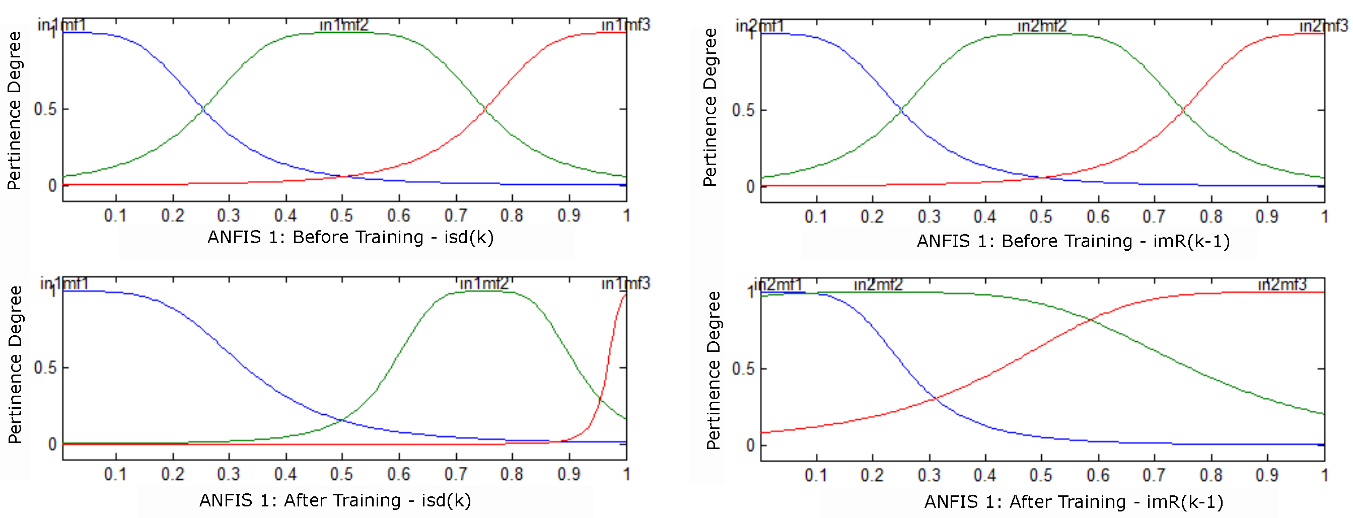
Figure 6.
Pertinences before training and after (A) – (B) .
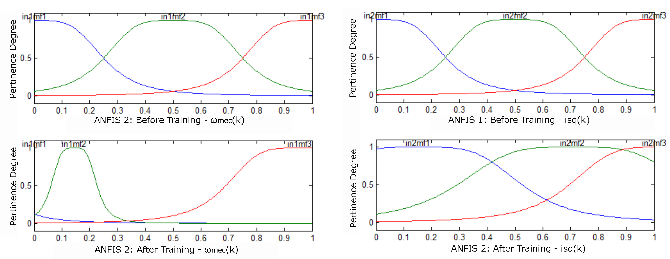
Figure 7.
Comparative result of mechanical speed with estimators.
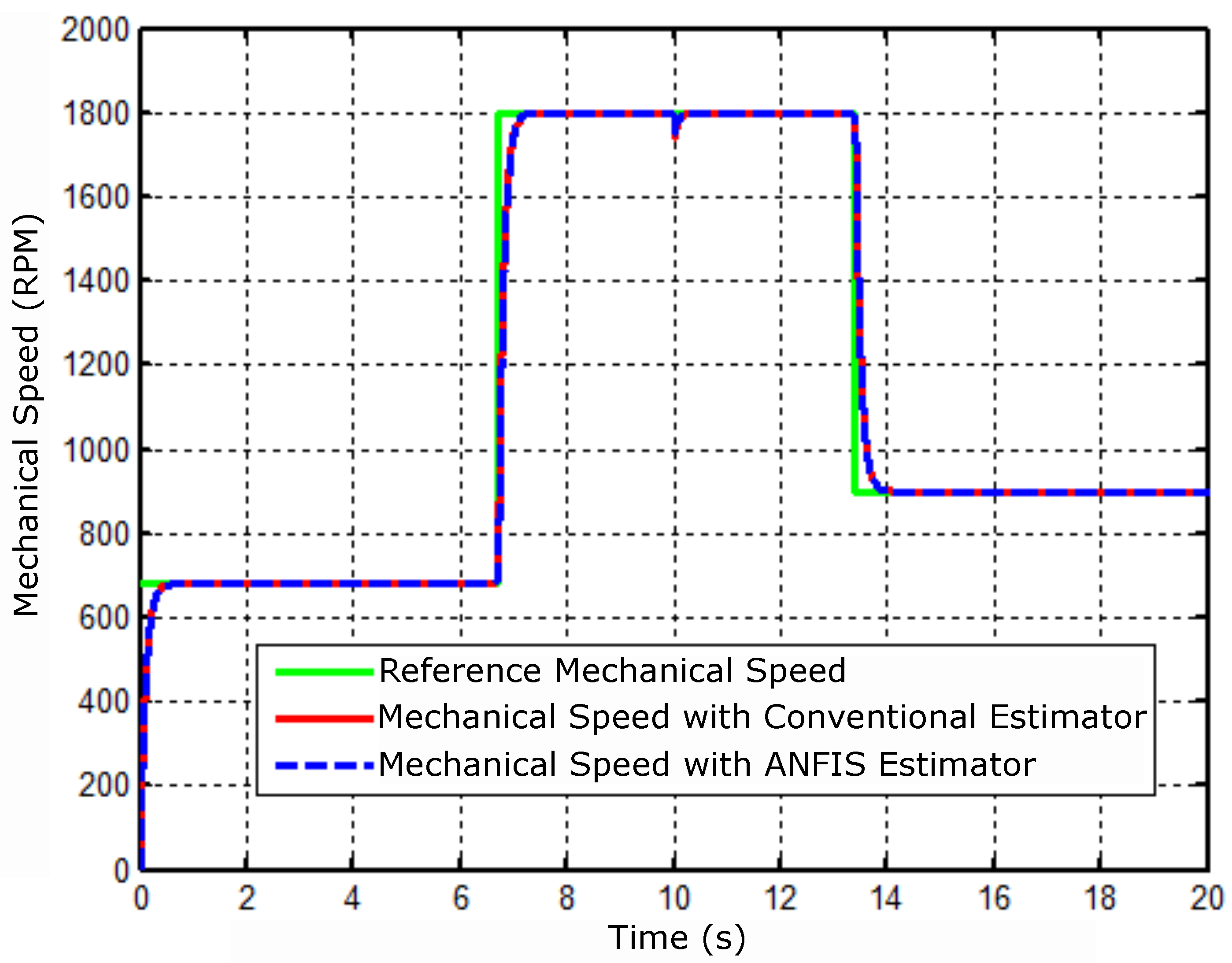
Figure 8.
Speed controller error signal.
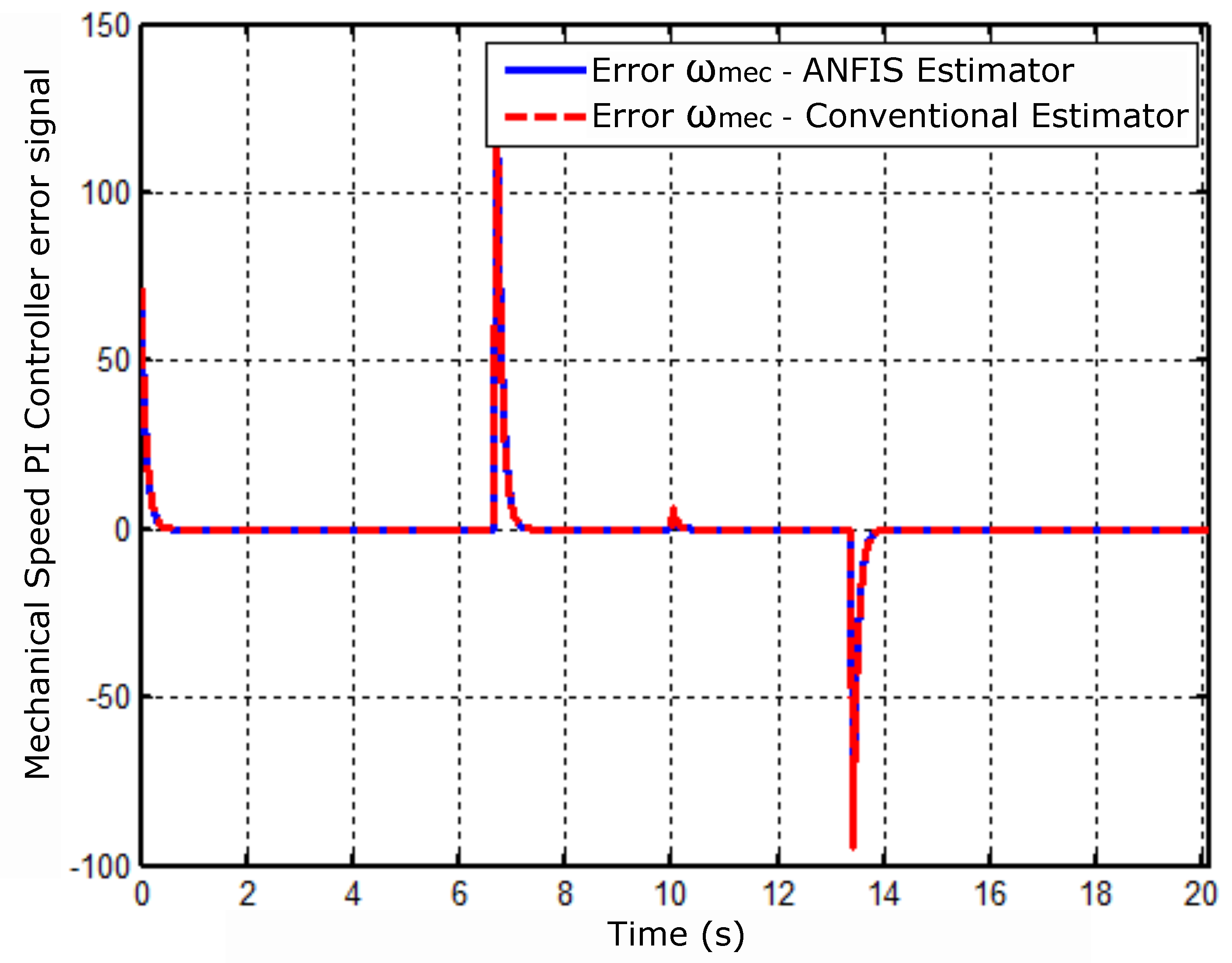
Figure 9.
Electrical torque response operating under simulation conditions.
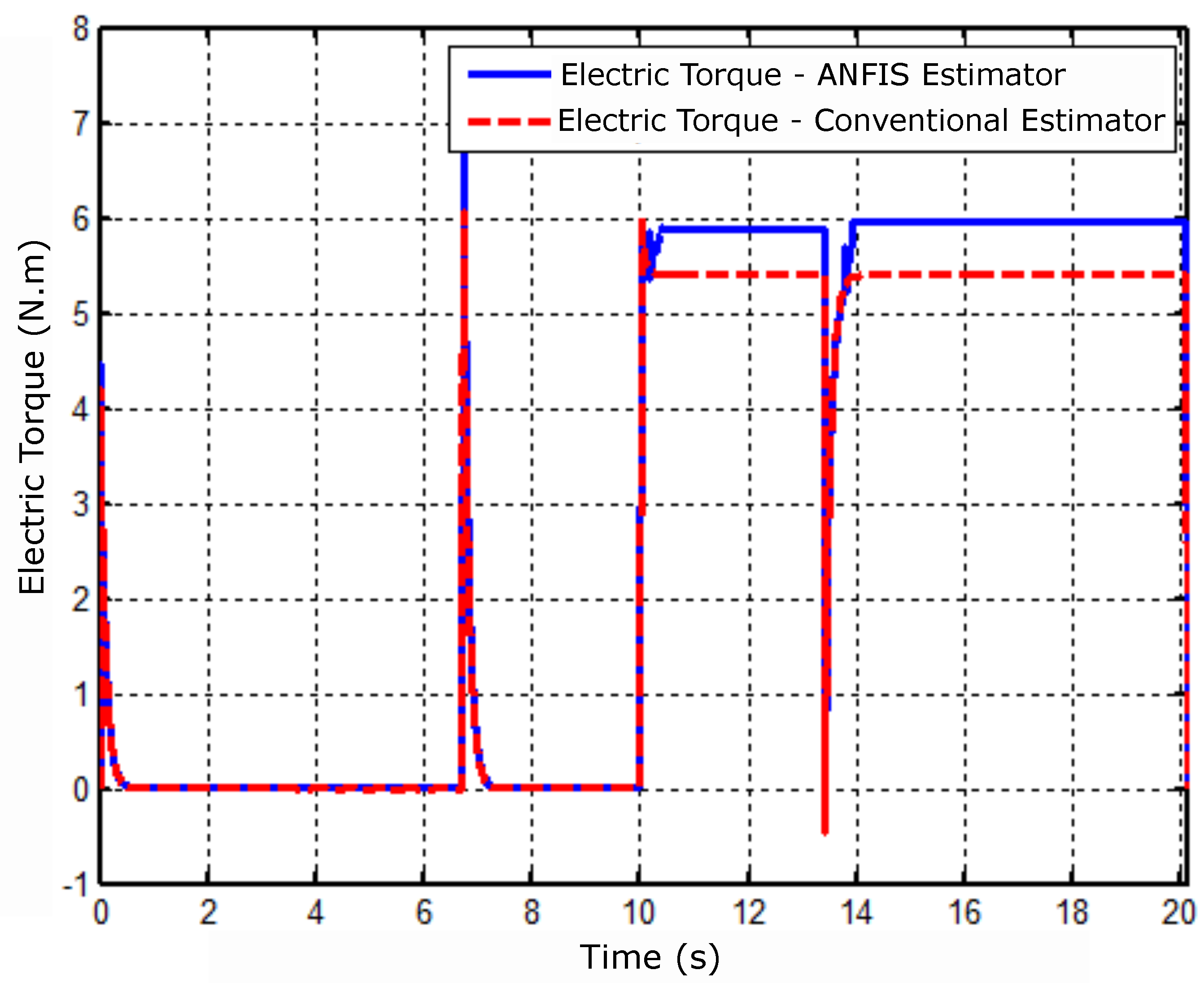
Figure 10.
Torque controller error signal.
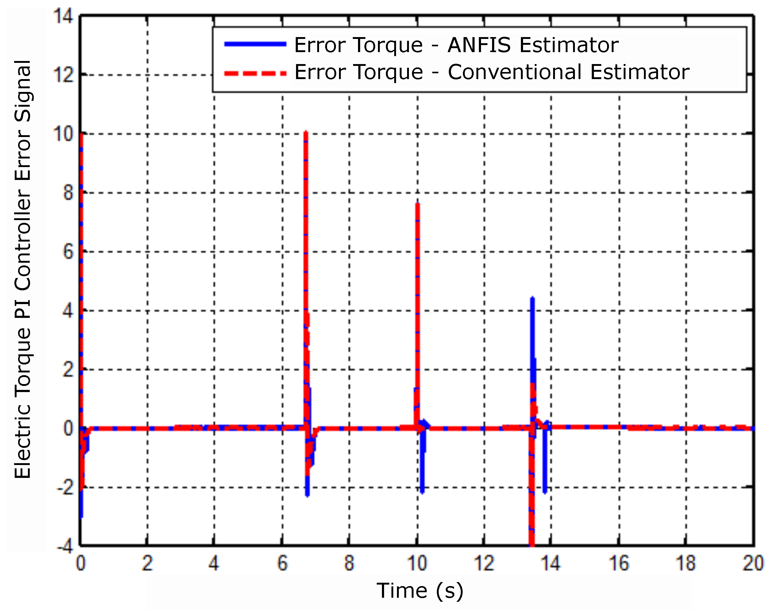
Figure 11.
Angular position result of the rotor flux.
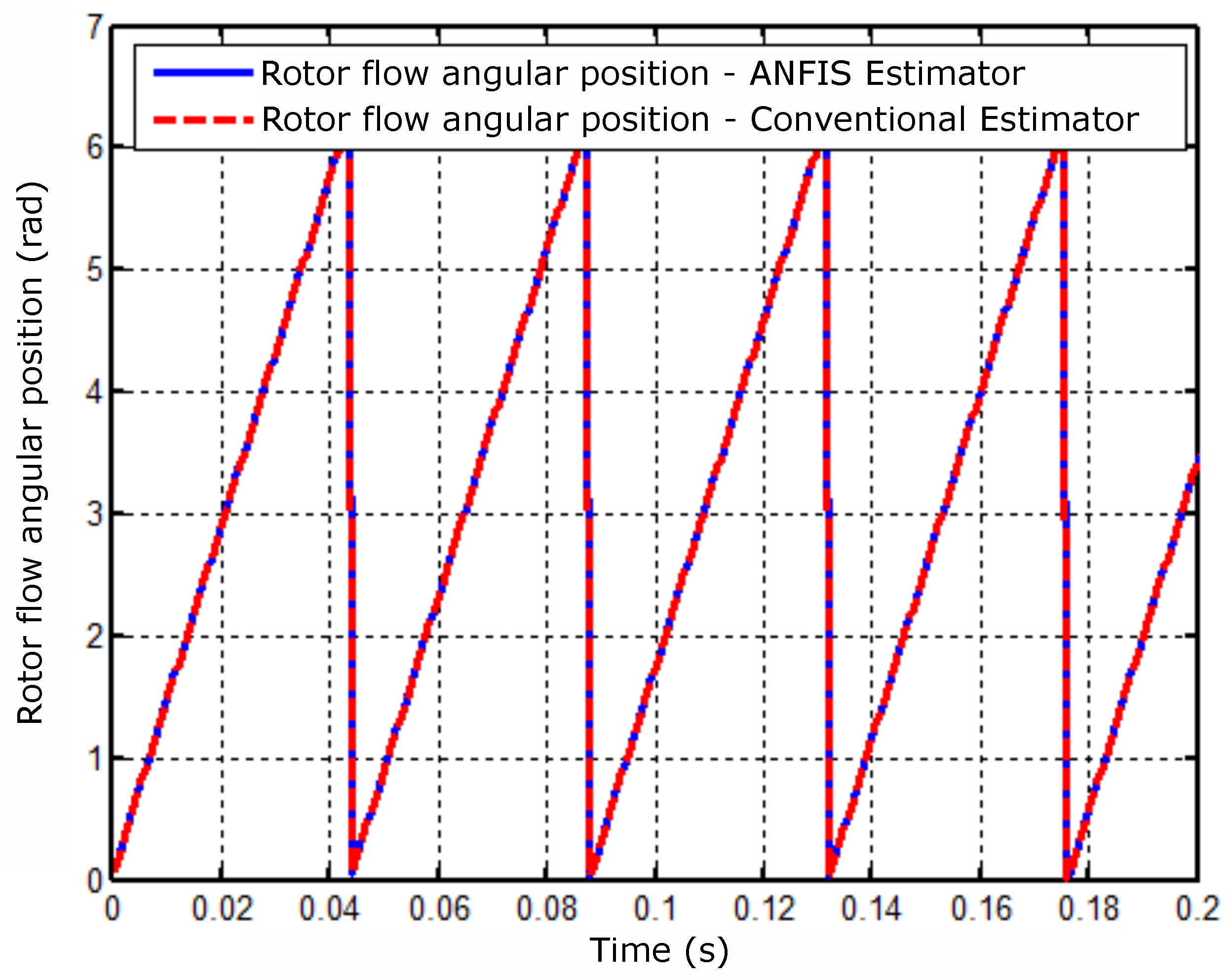
Figure 12.
Mean squared error for training with 847 epochs.
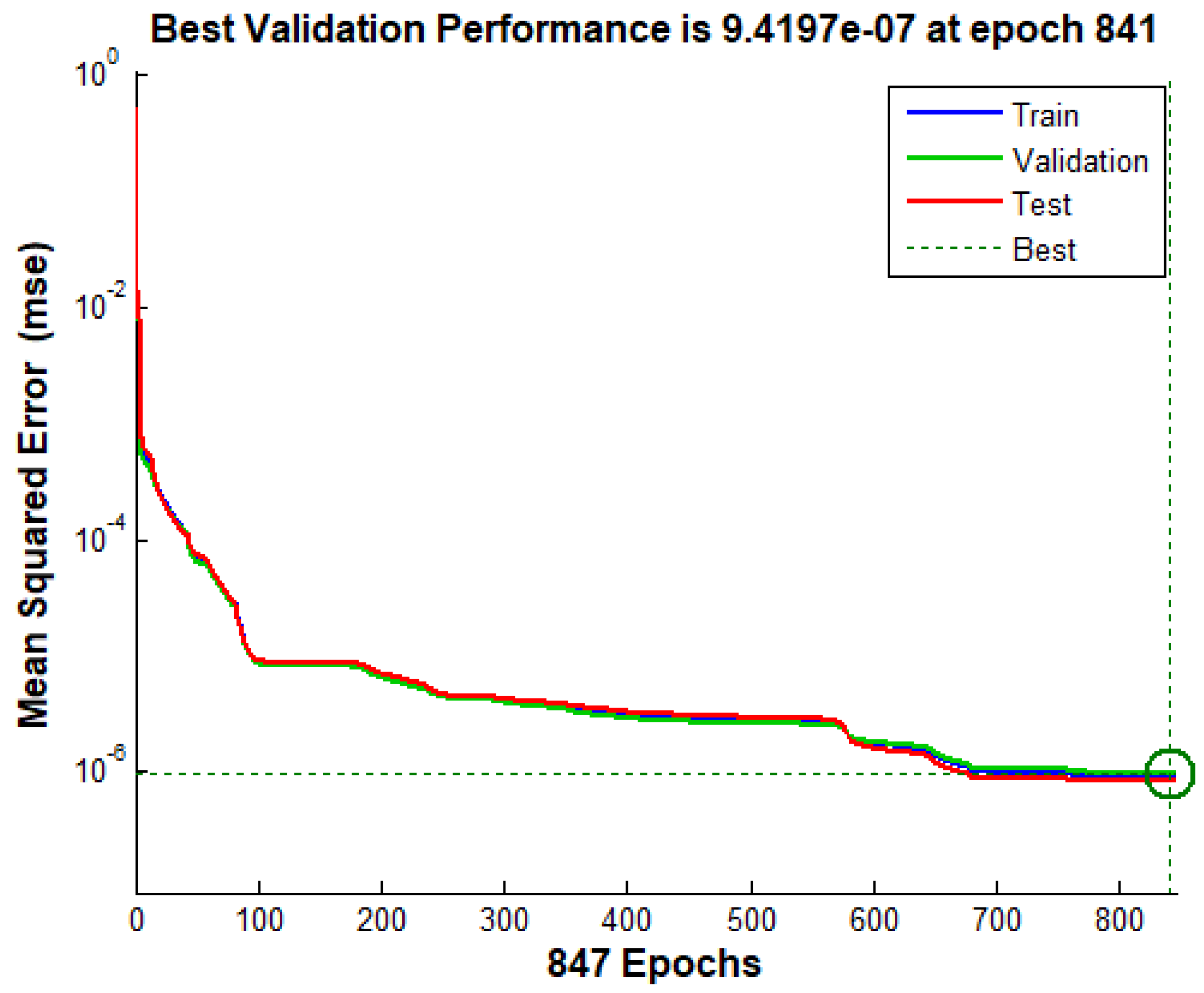
Figure 13.
Results of training (A), validation (B), and Neural Network tests (C).
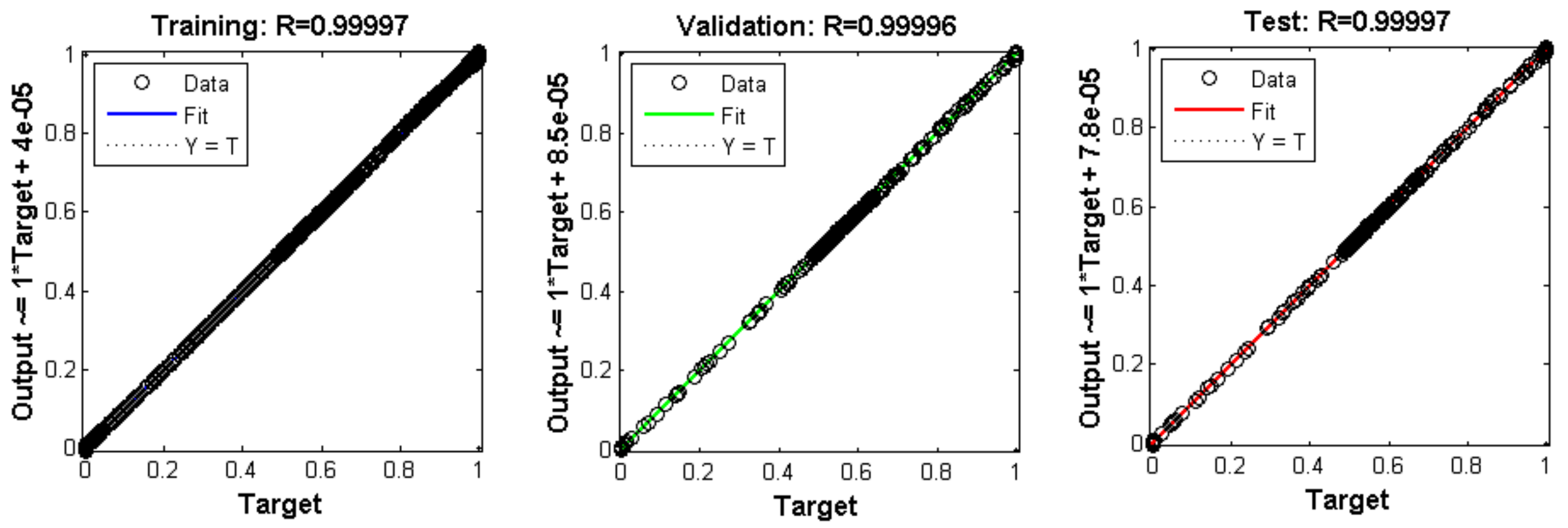
Figure 14.
Comparative result of the mechanical speed with the controllers: neural and PI.
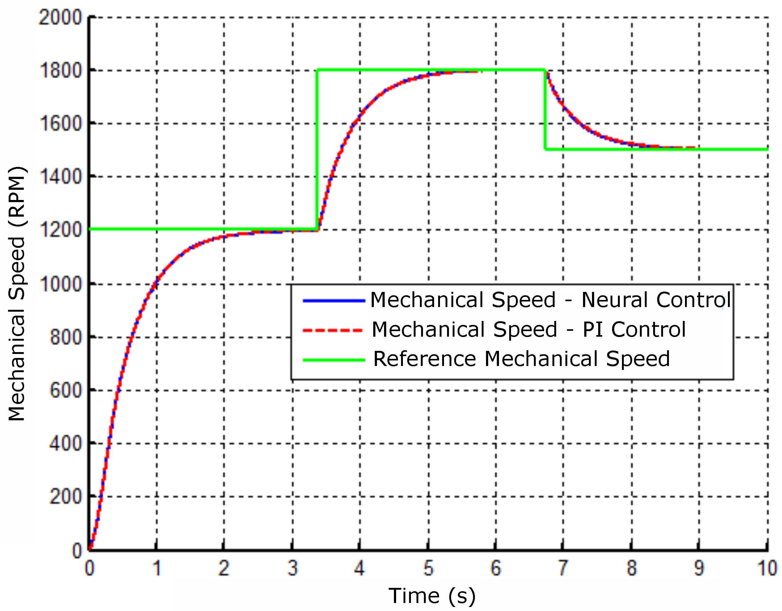
Figure 15.
Neural controller error signal and velocity PI.
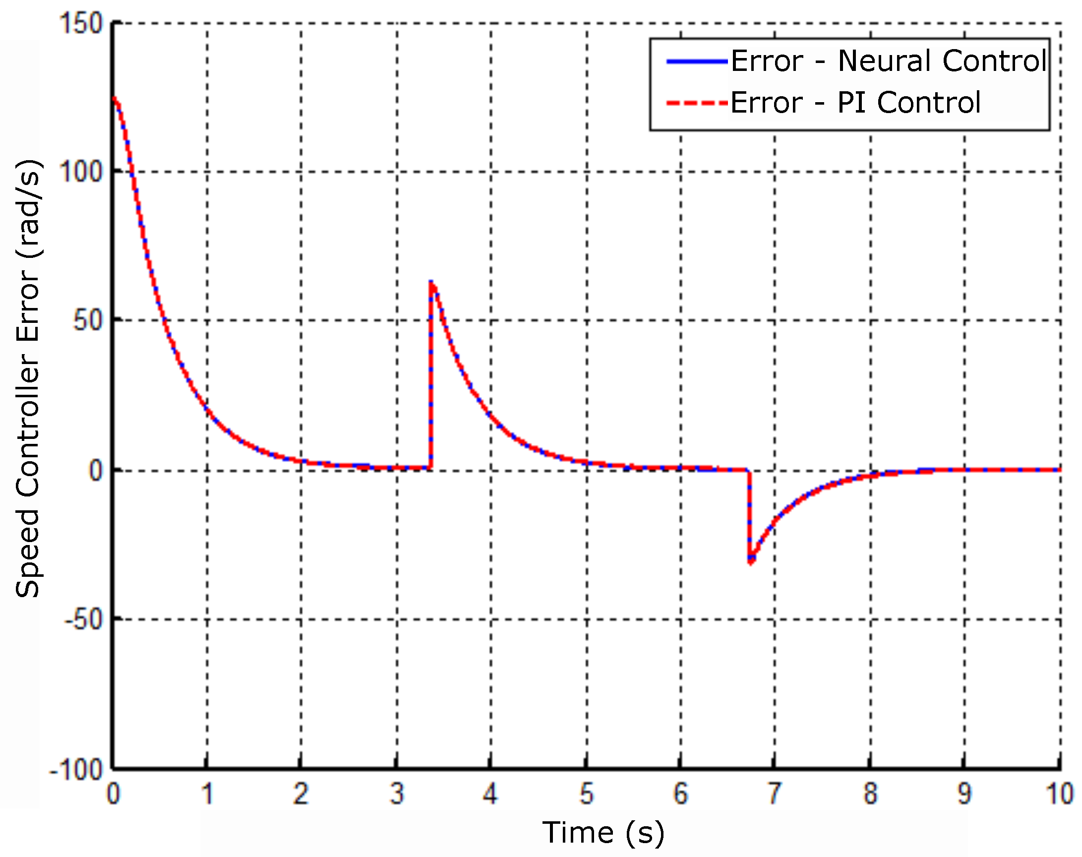
Figure 16.
Controller error signal operating with Neural Network and PI Control (A) - Electric torque and (B) - Magnetizing current.
Figure 16.
Controller error signal operating with Neural Network and PI Control (A) - Electric torque and (B) - Magnetizing current.
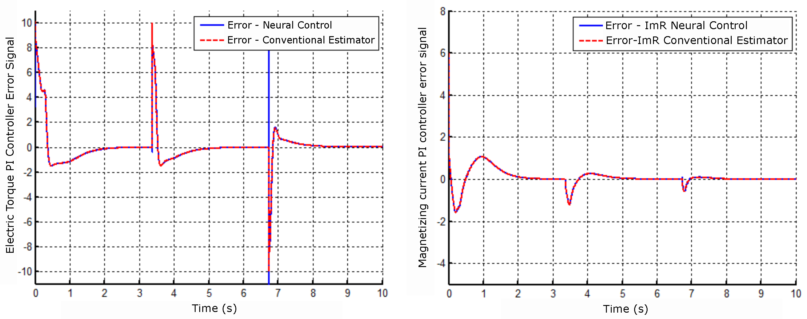
Figure 17.
Angular position result of the rotor flux with the neural controller and PI of velocity.
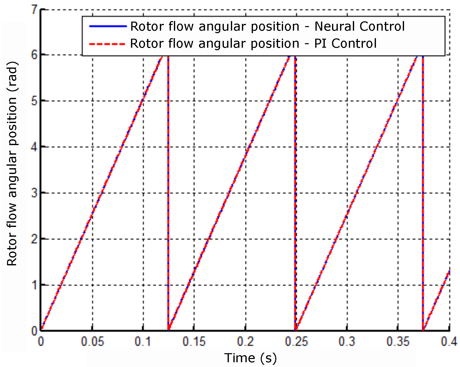
Figure 18.
Motor-bearing shaft eccentricities. Source: Victor, 2012.
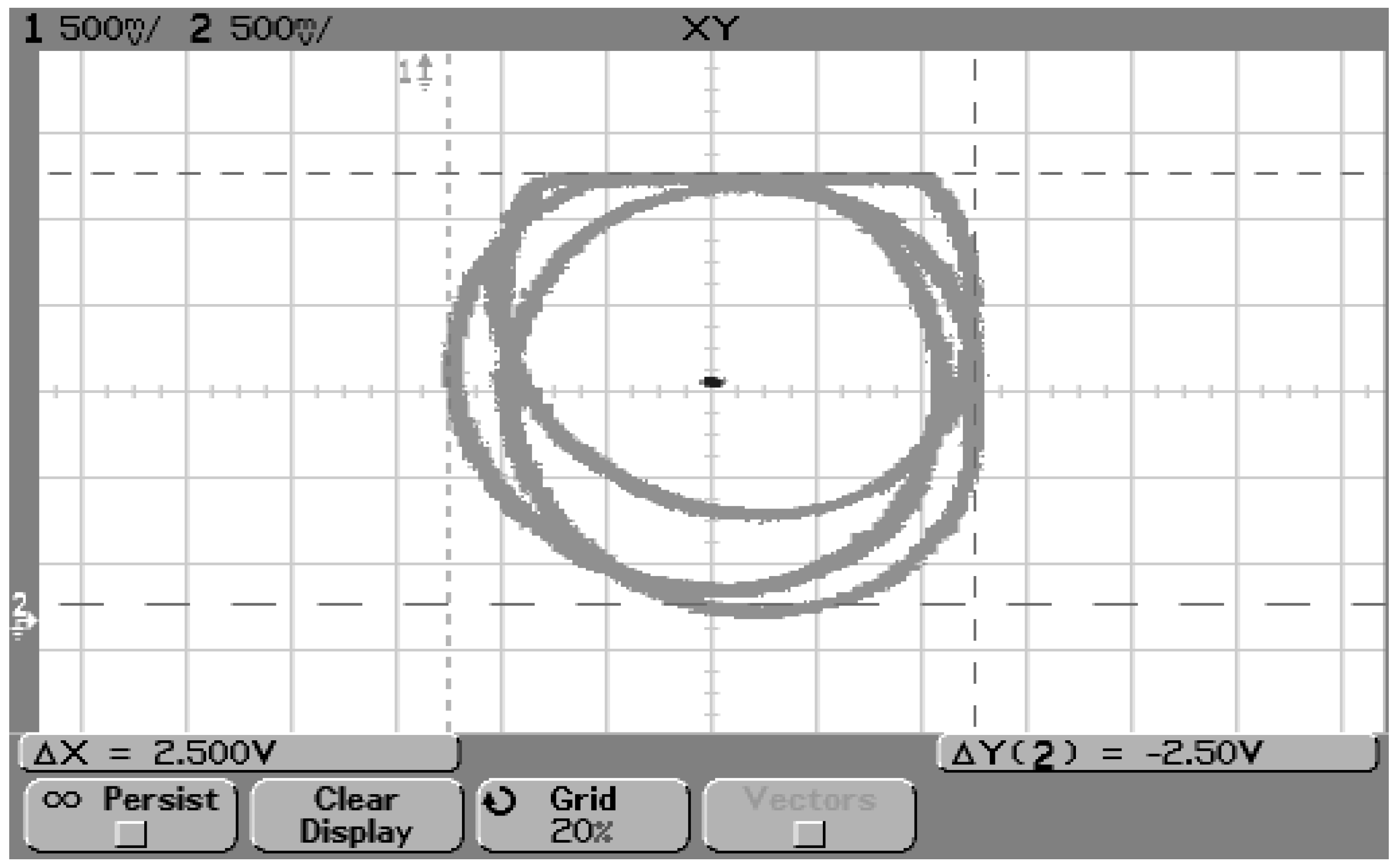
Figure 19.
Coverless bearing motor with identification of the coil groups.
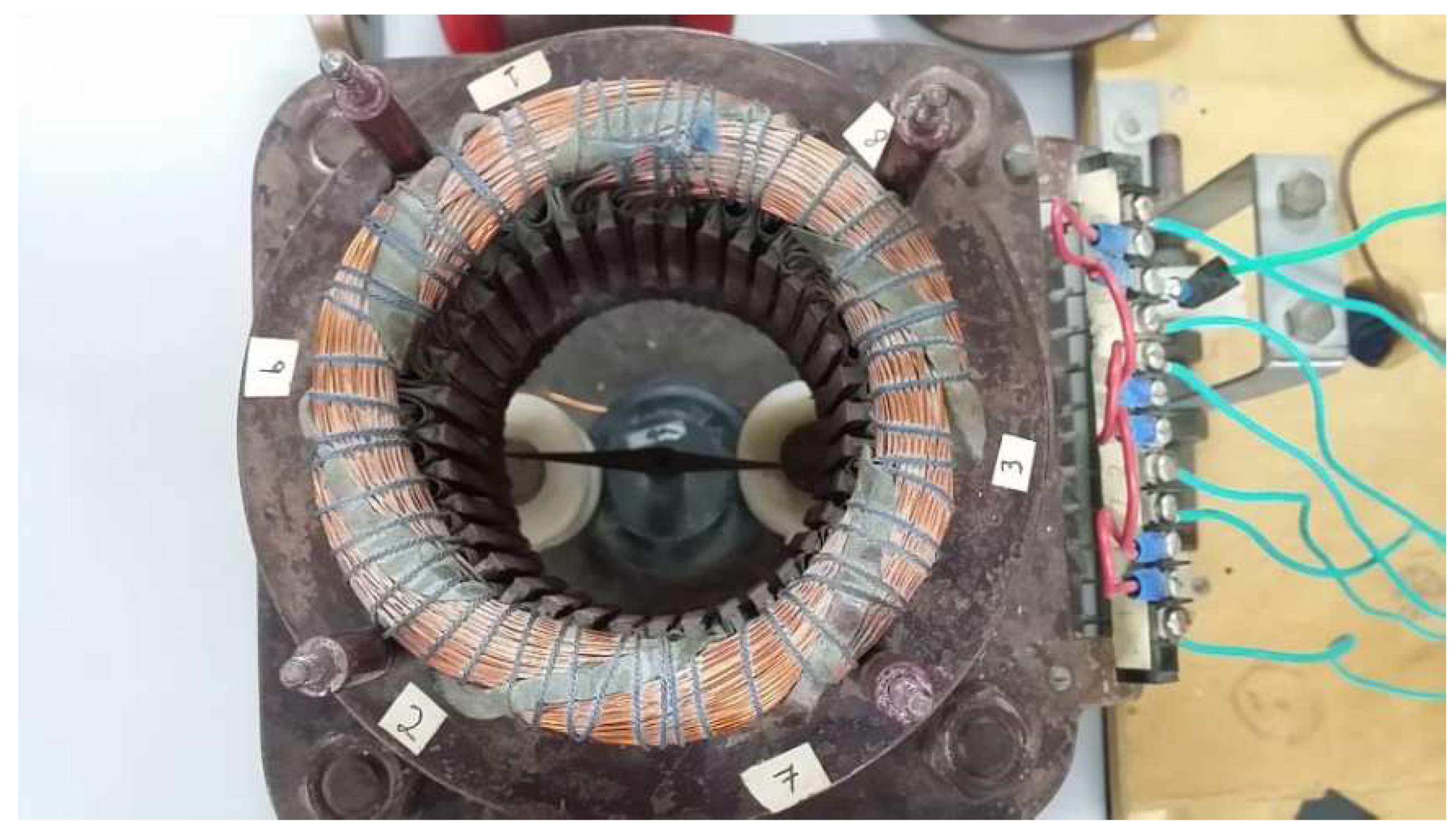
Figure 20.
Motor-bearing winding connection arrangement.
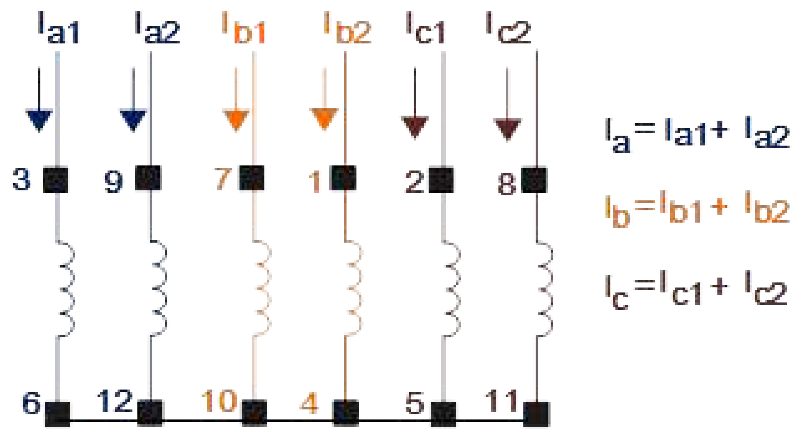
Figure 21.
Bearing motor winding connection arrangement. The result identified each coil group according to the sequence of Figure 20.
Figure 21.
Bearing motor winding connection arrangement. The result identified each coil group according to the sequence of Figure 20.
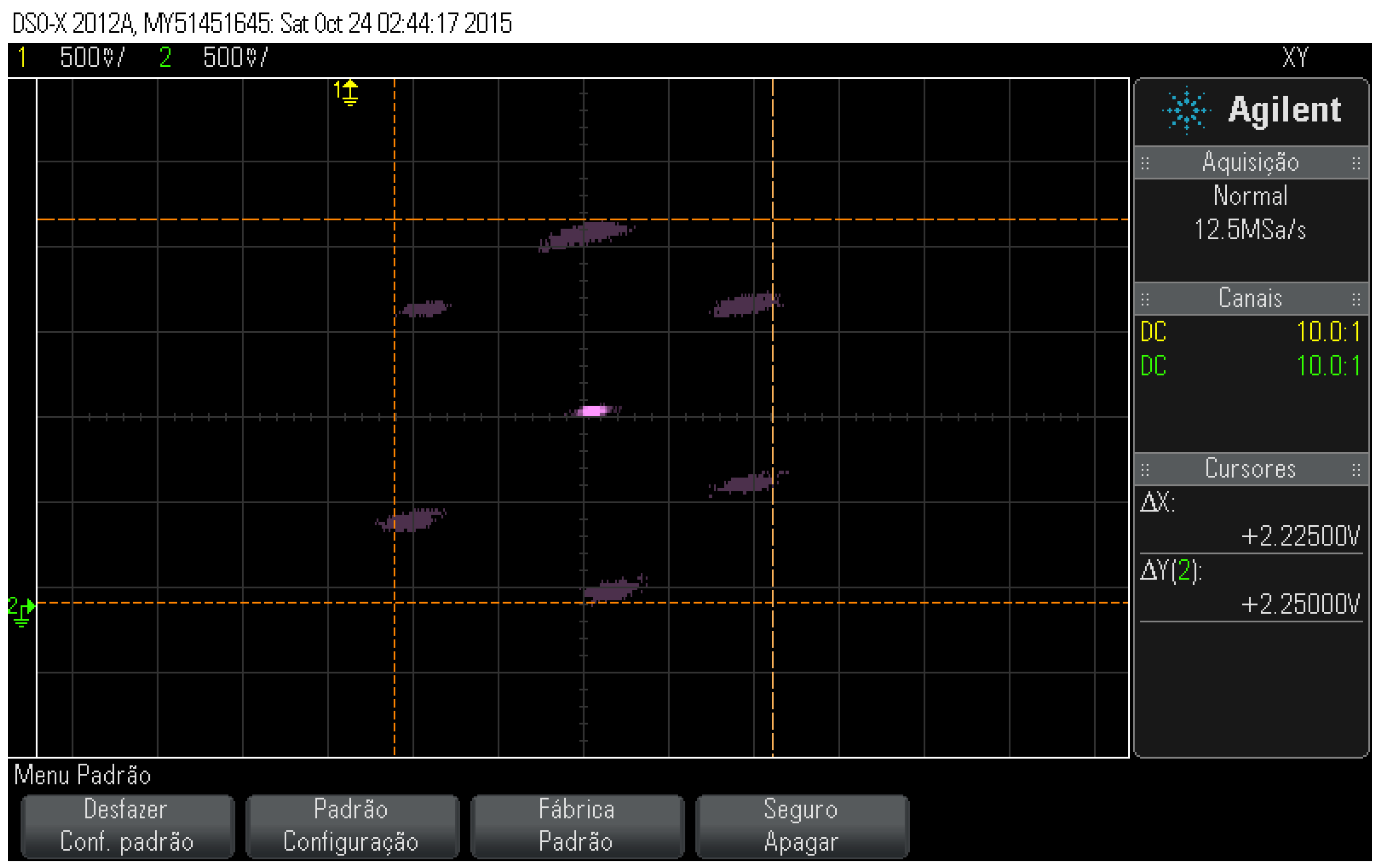
Figure 22.
Electronic circuit used with the AEC 5505-04 sensor. Source: [18].
Figure 22.
Electronic circuit used with the AEC 5505-04 sensor. Source: [18].
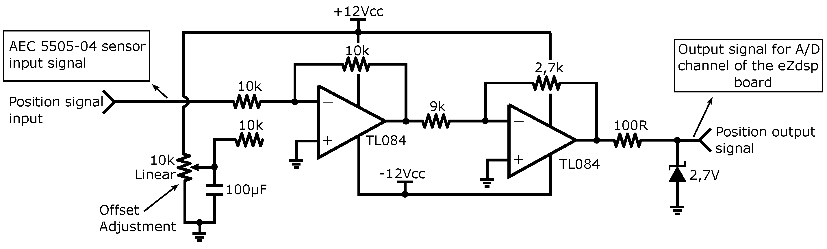
Figure 23.
Unwanted and desired radial displacement for position control.
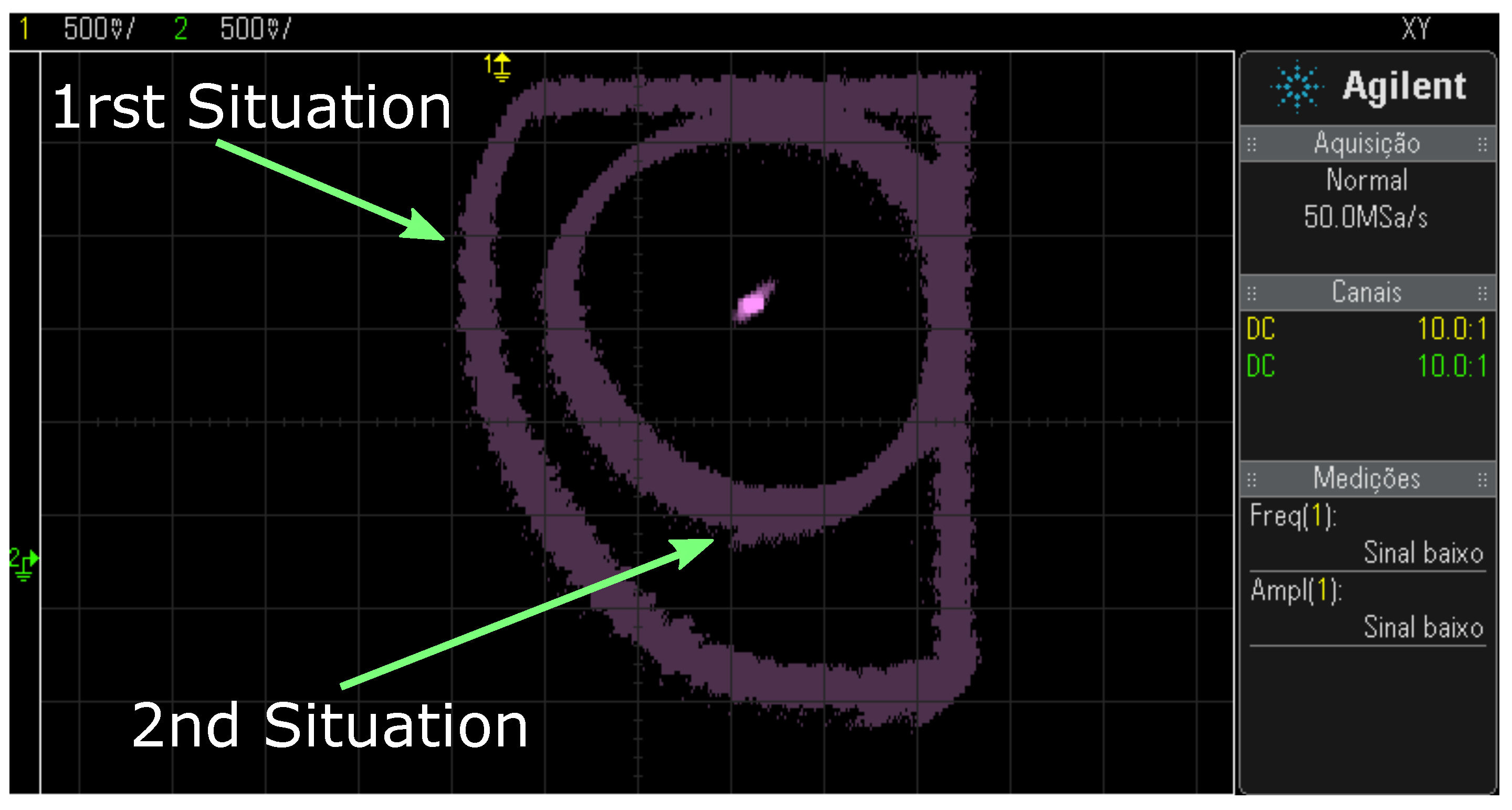
Figure 24.
(A) Radial displacement reaping in the Y coordinate and (B) the sensor signals X (green) and Y (yellow) in oscilloscope free mode.
Figure 24.
(A) Radial displacement reaping in the Y coordinate and (B) the sensor signals X (green) and Y (yellow) in oscilloscope free mode.
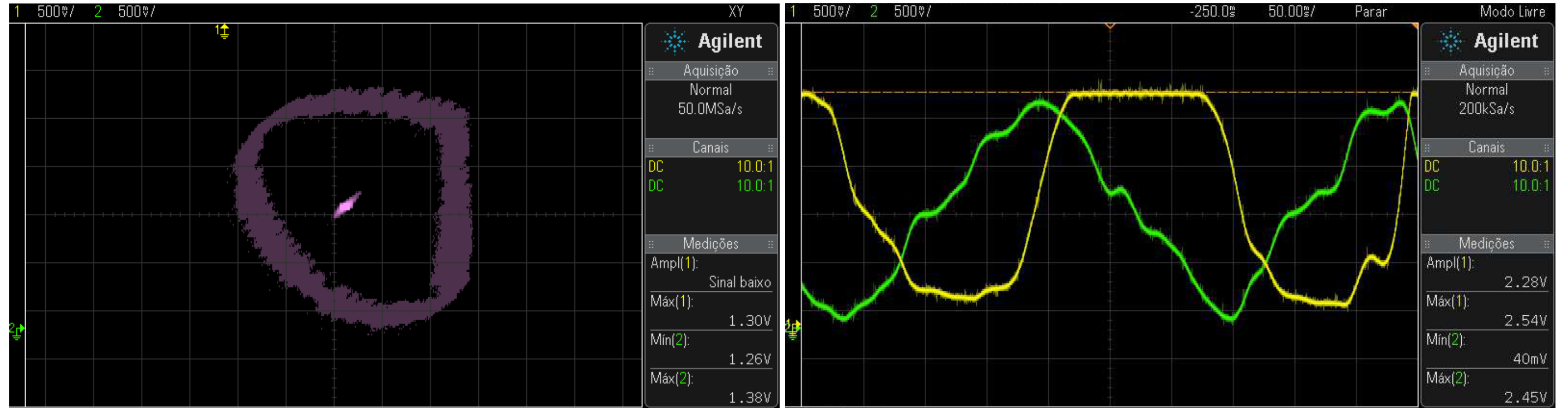
Figure 25.
Behavior of the signals after adjusting the offset of the sensors.
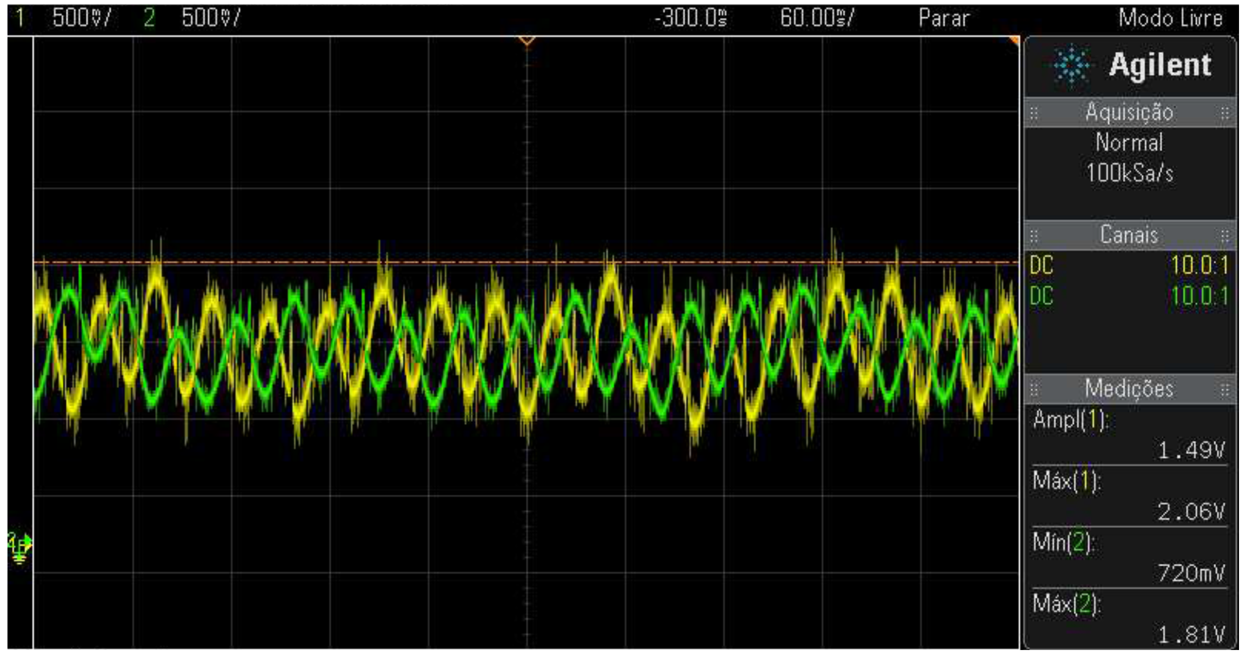
Figure 26.
Radial displacement limit of the rotor.
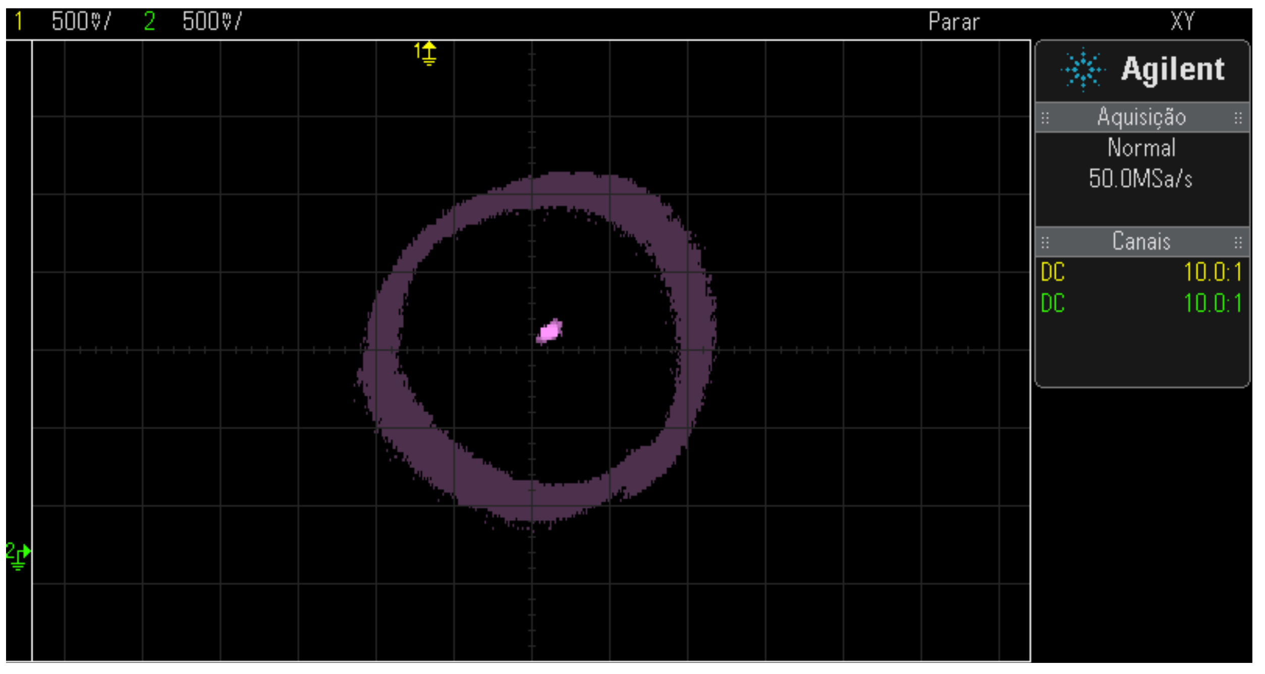
Figure 27.
Mechatronic system with interfaces and the bearing motor.
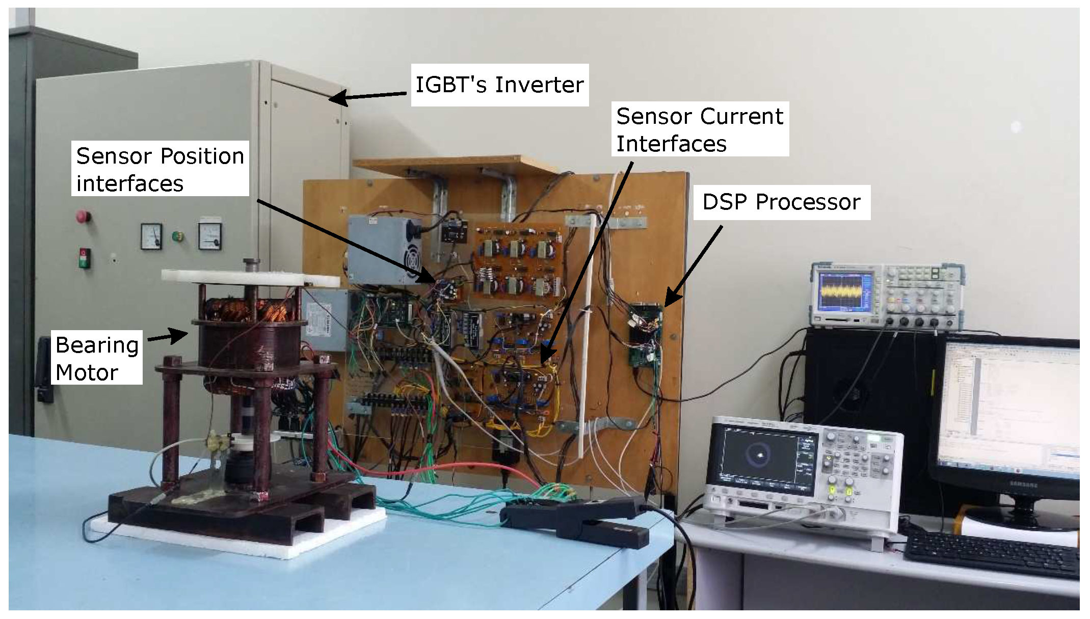
Figure 28.
Control structure with flux estimator.
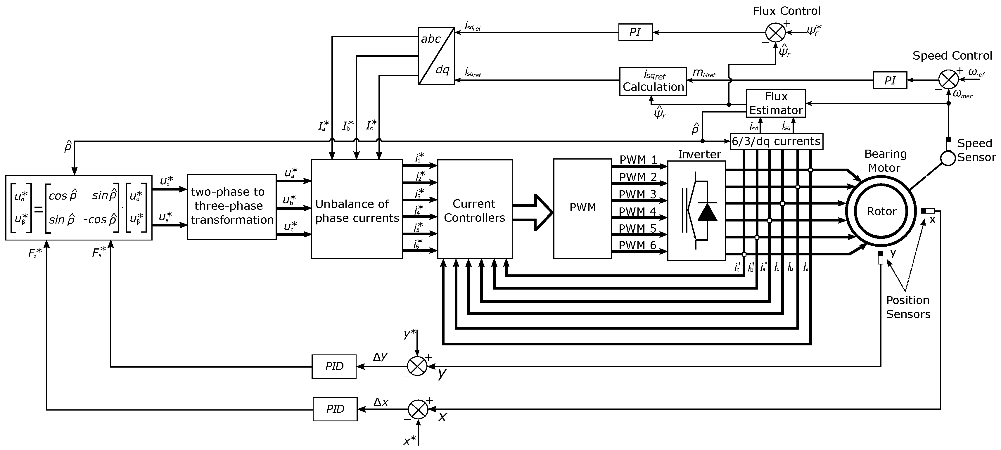
Figure 29.
Bearing motor cascade control diagram.
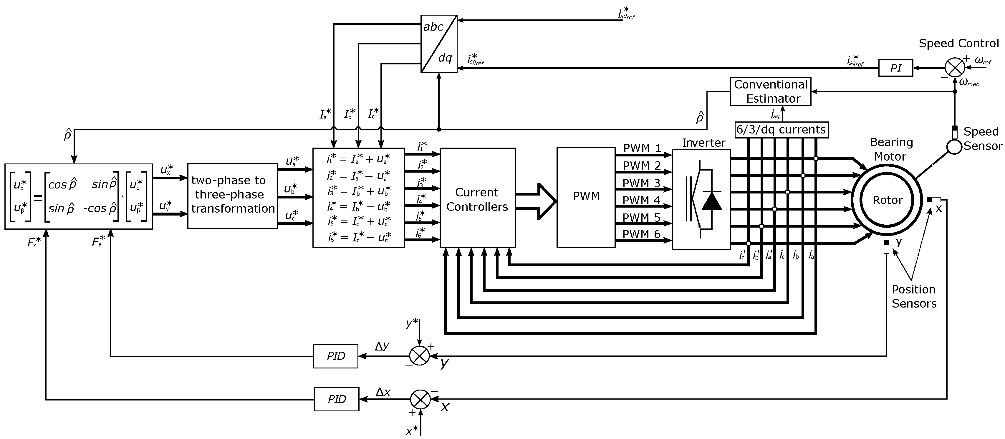
Figure 30.
Motor-bearing current control.
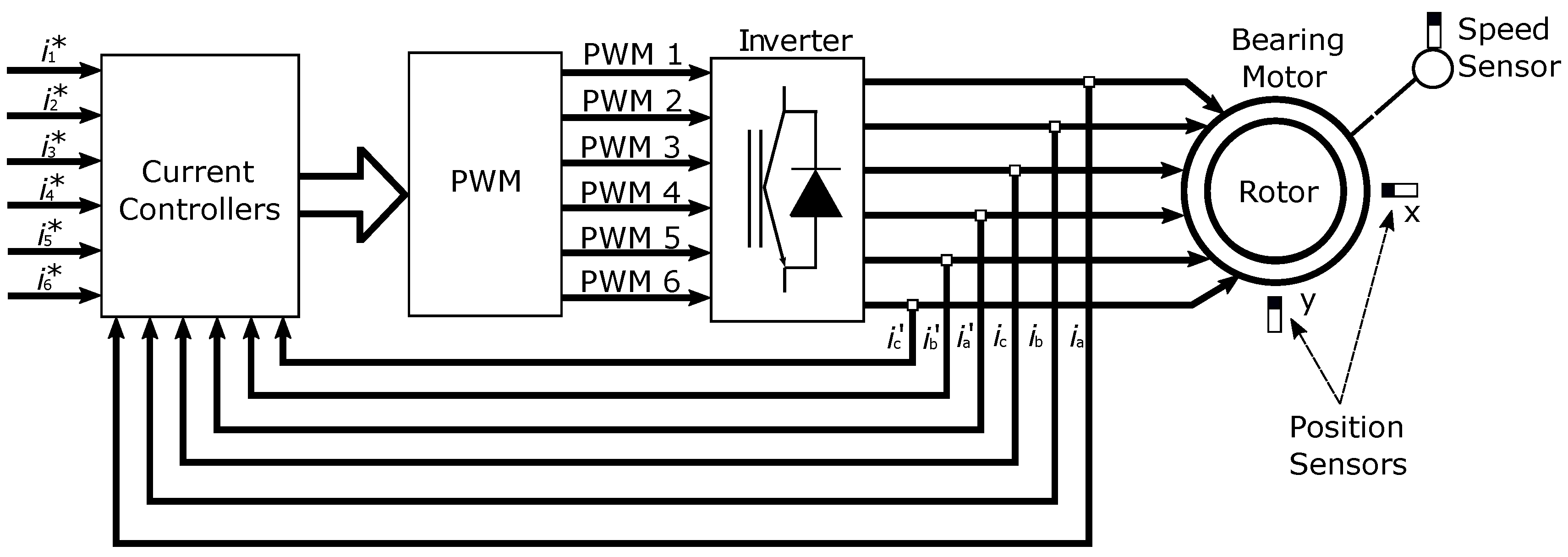
Figure 31.
Response to the reference change in coil 1.
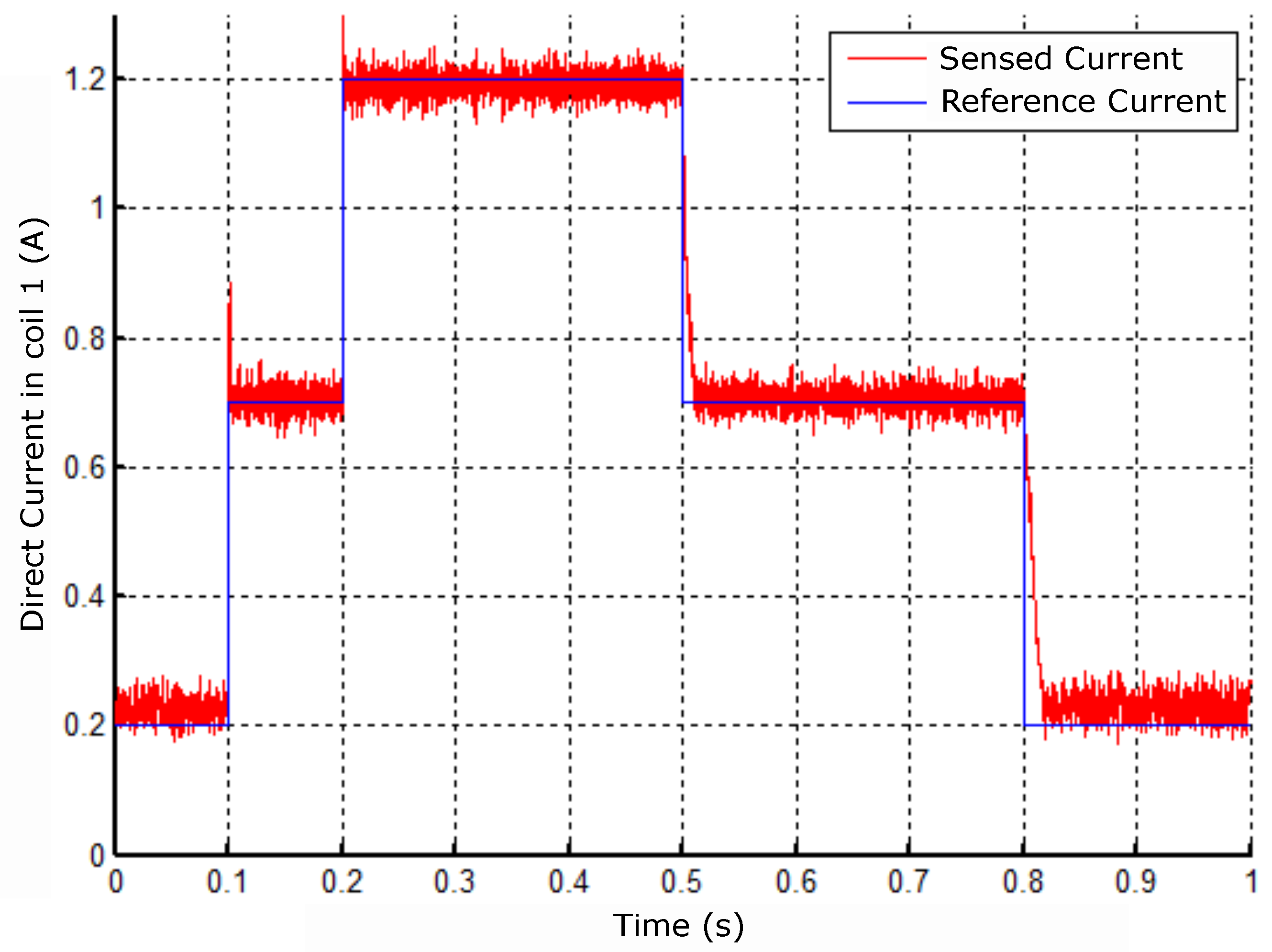
Figure 32.
Response to sinusoidal reference in coil 1.
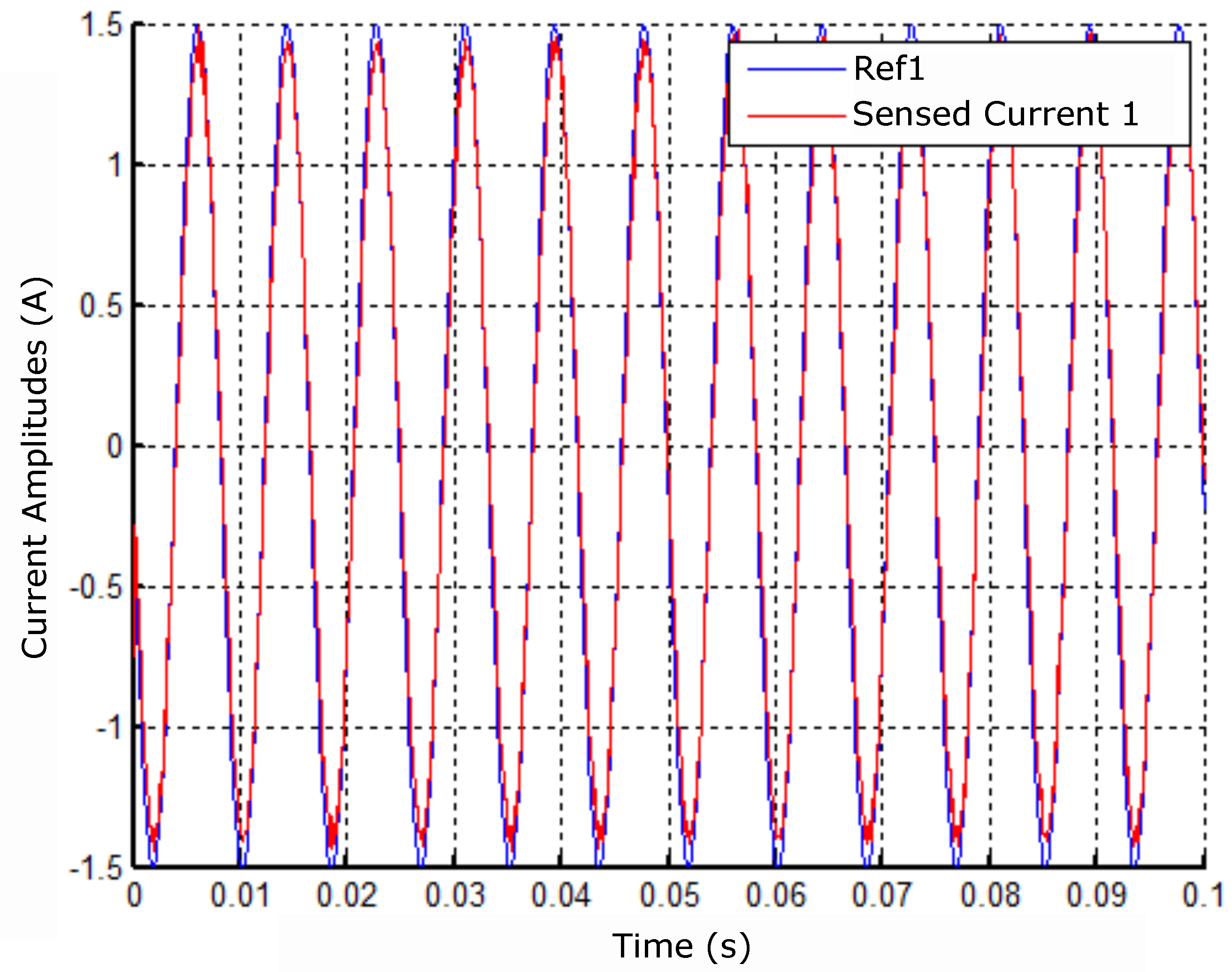
Figure 33.
Lagged currents at 15Hz frequency and A amplitude.
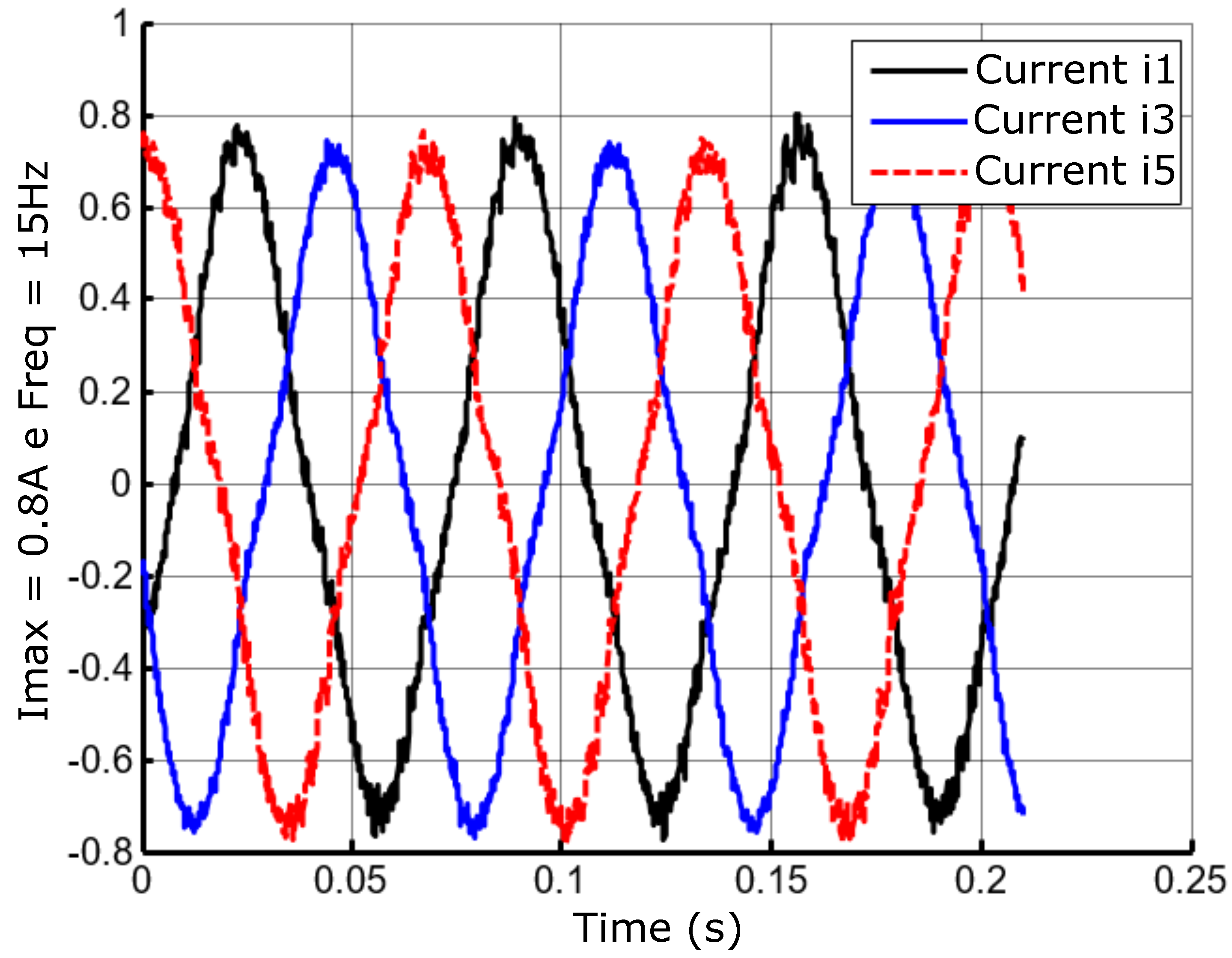
Figure 34.
Lagged currents at the frequency of 30Hz and amplitude A.
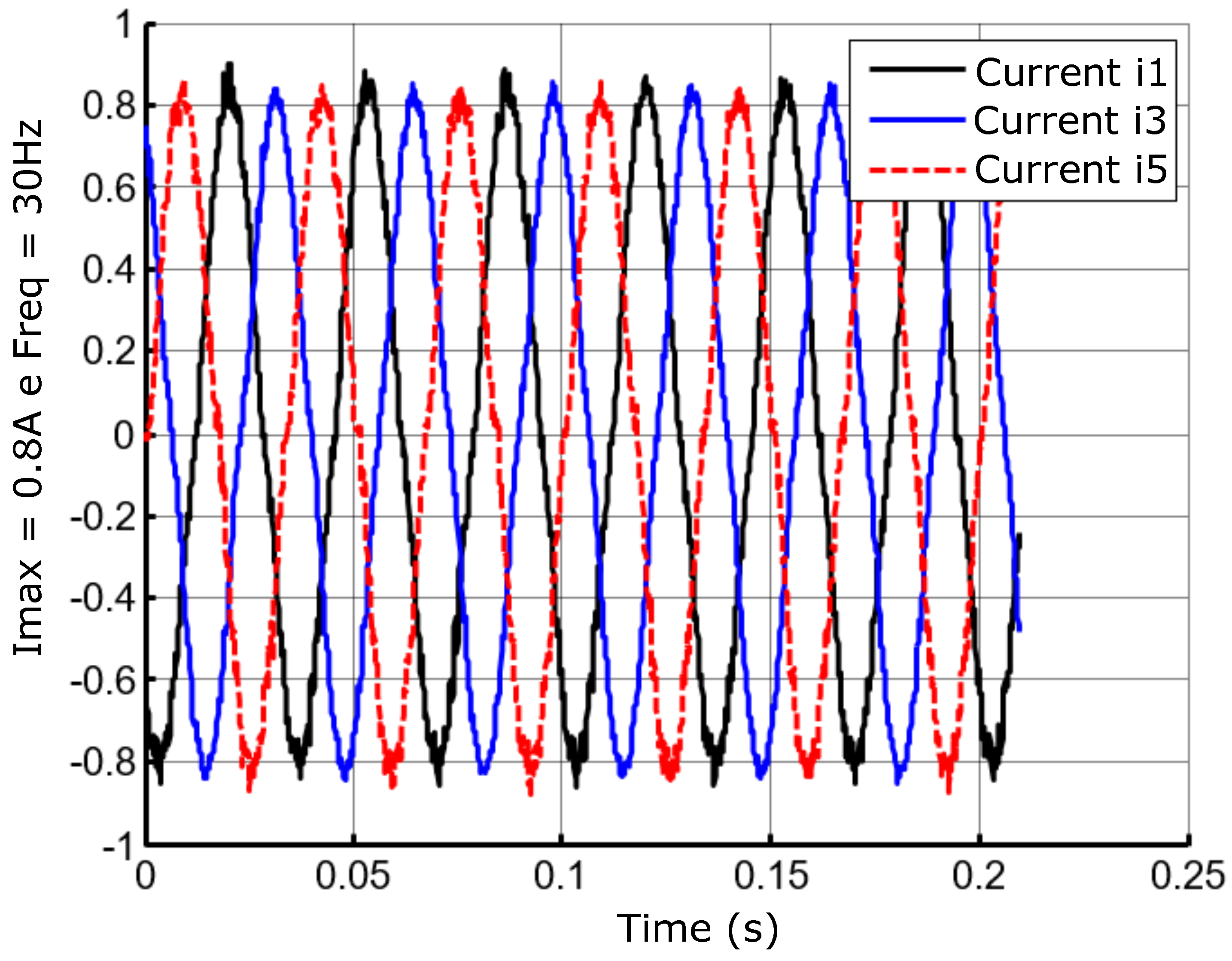
Figure 35.
Lagged currents at the frequency of 60Hz and amplitude A.
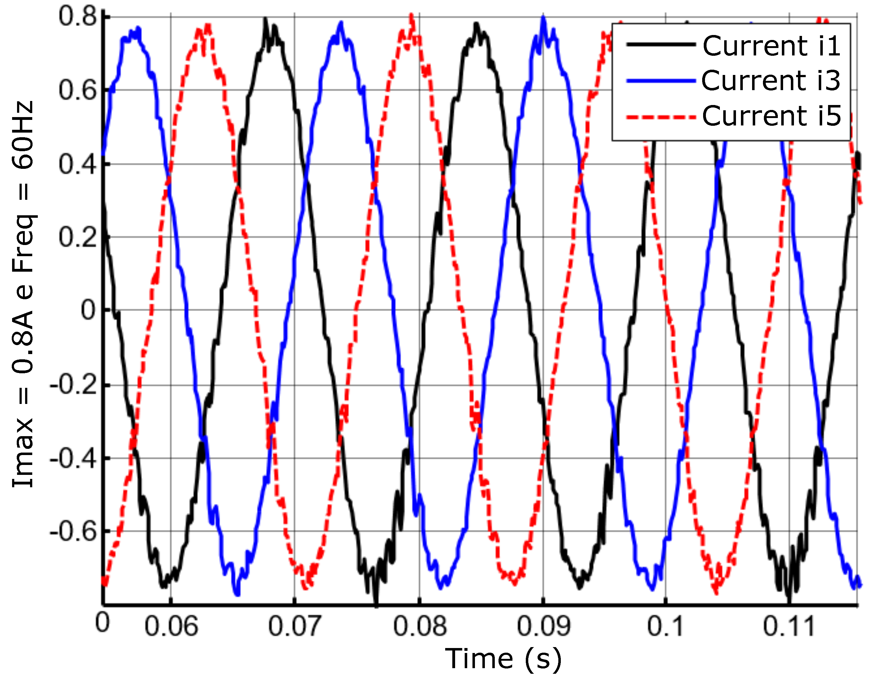
Figure 36.
Lagged currents at the frequency of 60Hz and amplitude A.
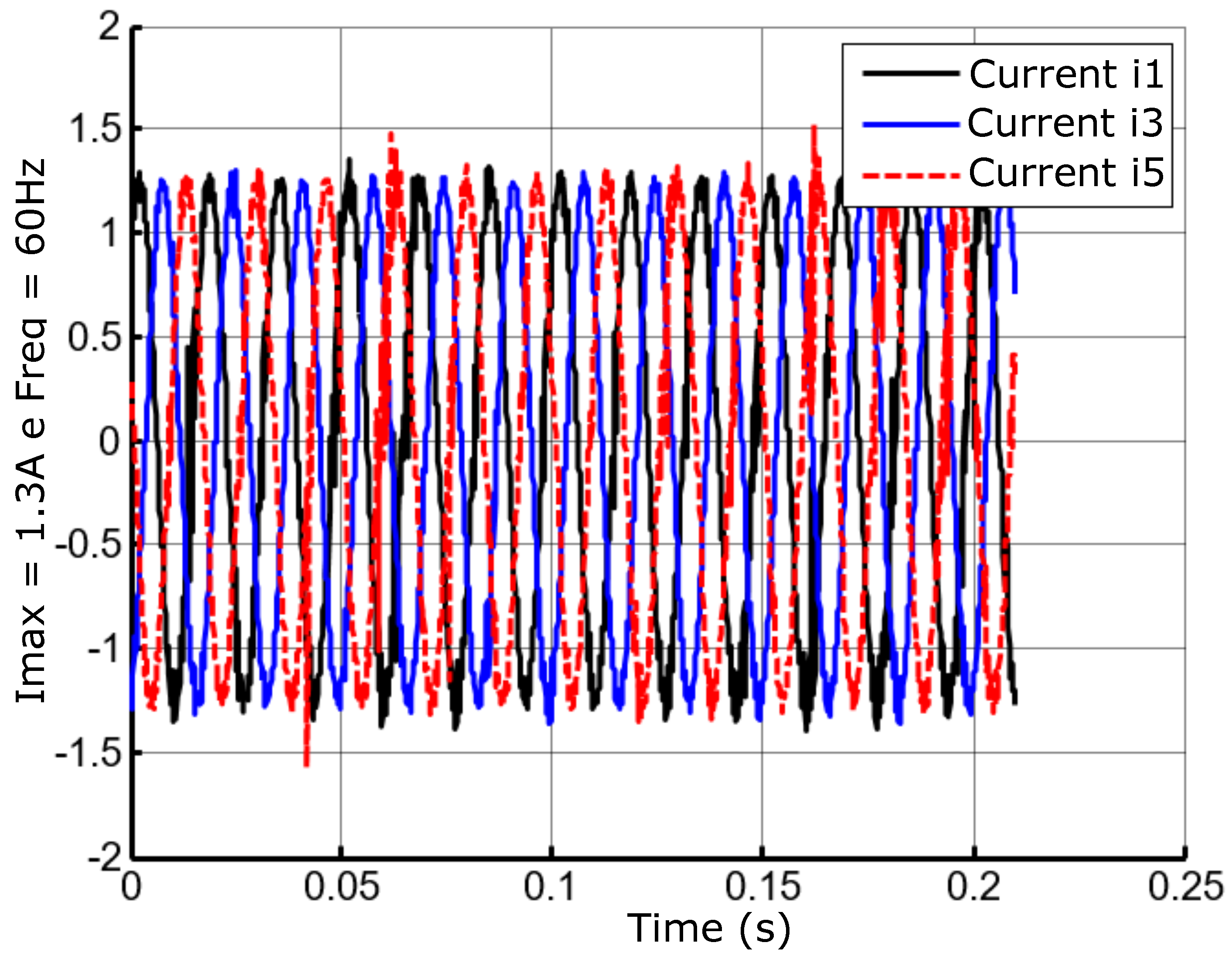
Figure 37.
Cascade position control with motor-bearing current control.
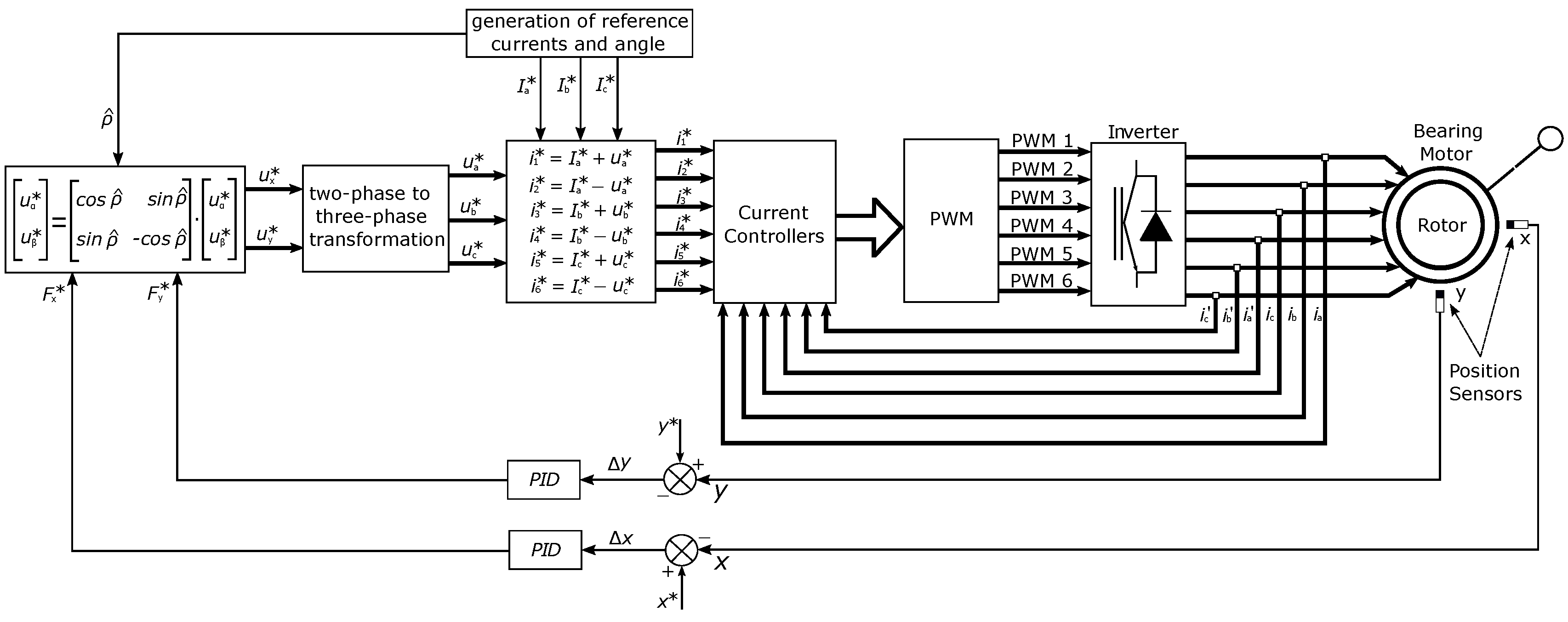
Figure 38.
Position control results for the X axis.
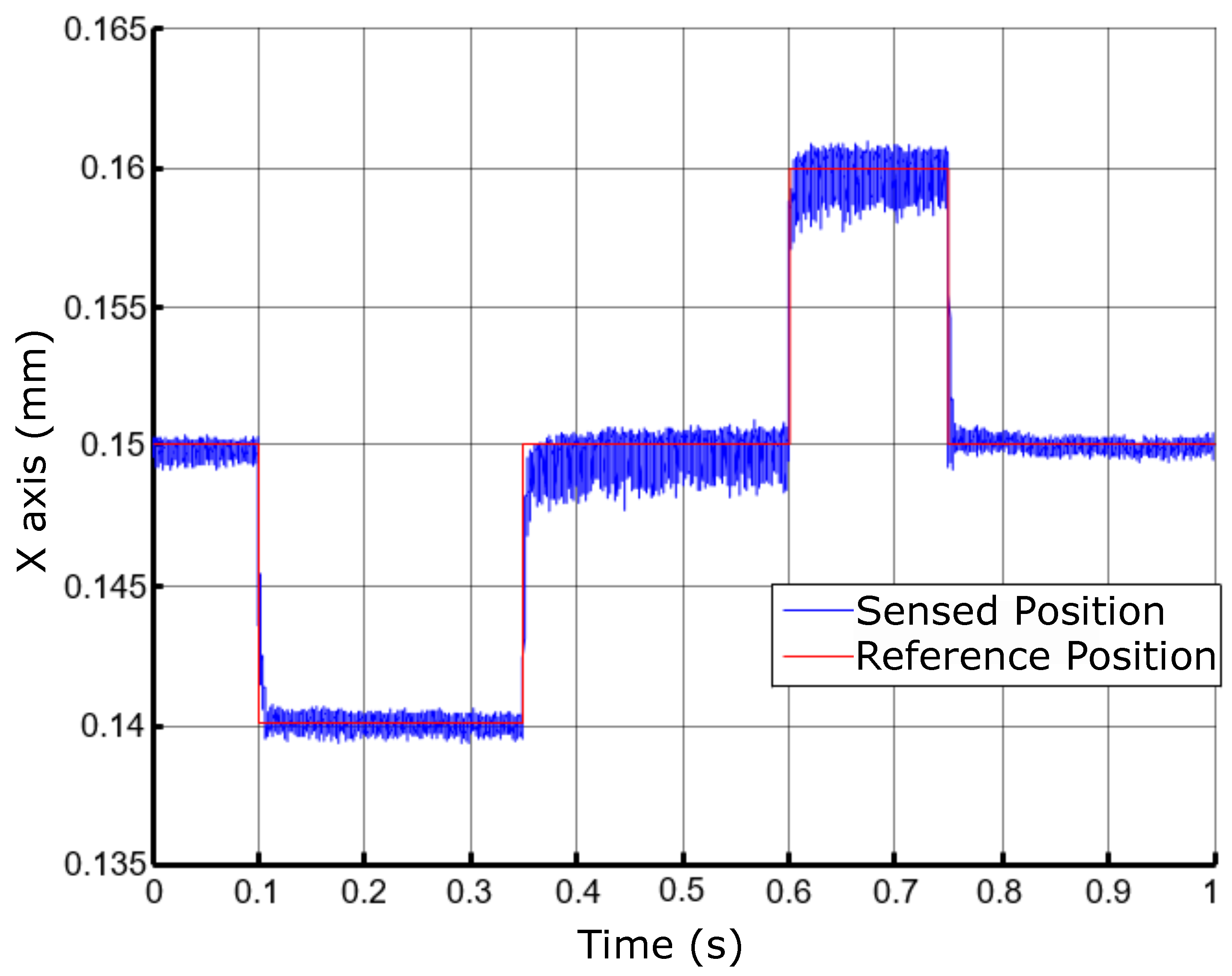
Figure 39.
Position control results for the Y axis.
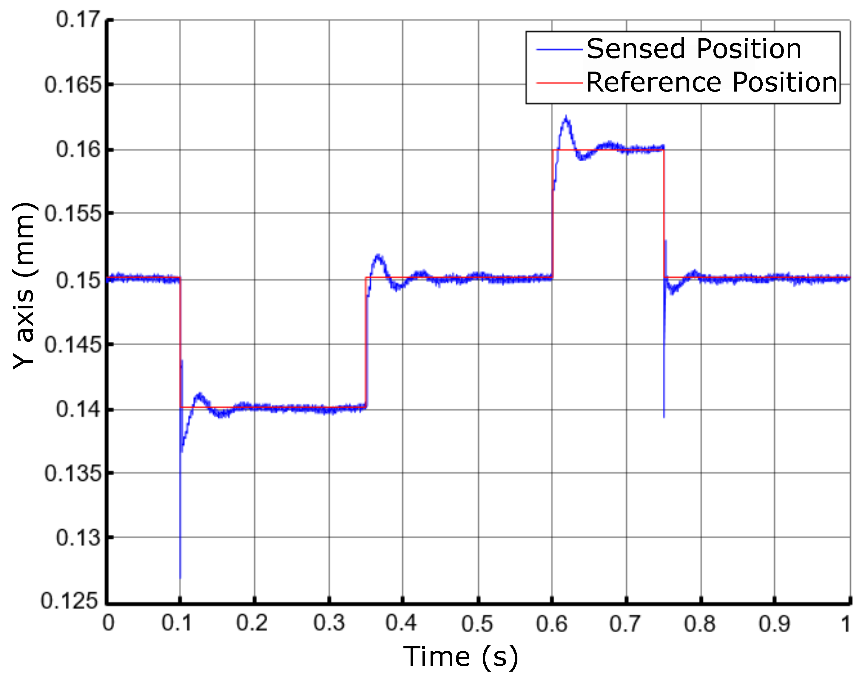
Figure 40.
Position control results with a rotor scatter area for activation at 60Hz.
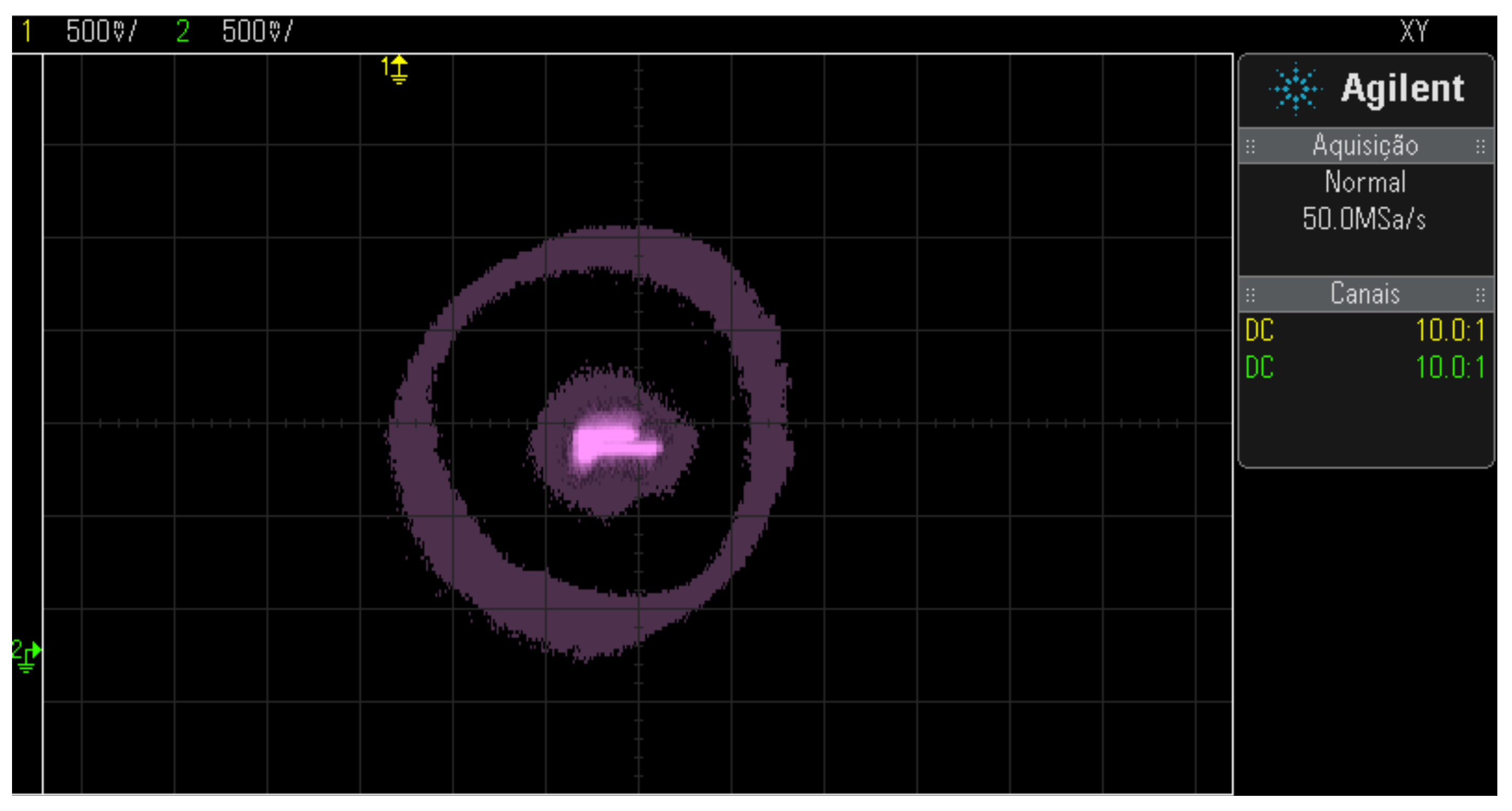
Figure 41.
Position control results with an area of dispersion from the rotor to the 15Hz drive.
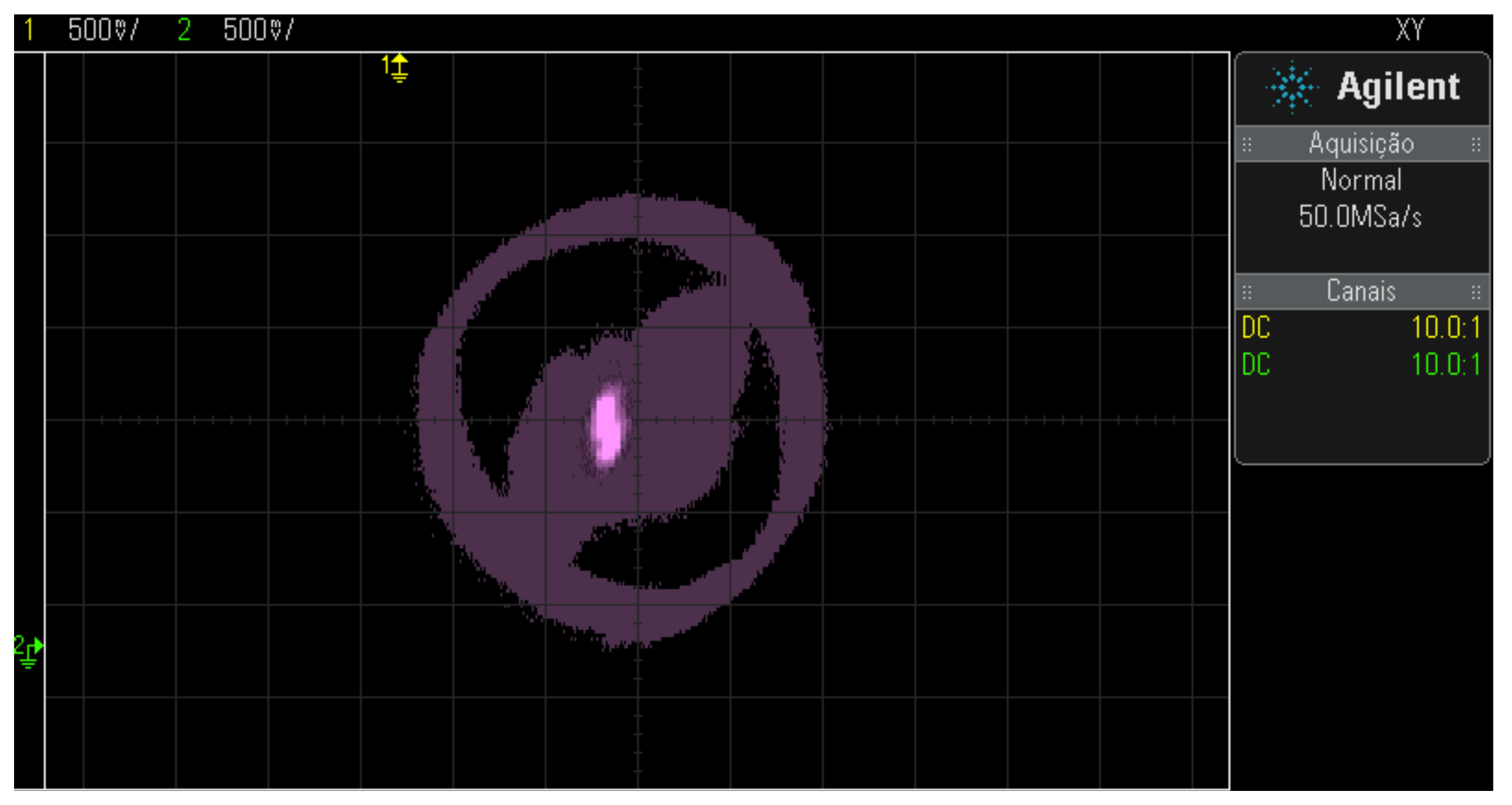
Figure 42.
Position control results with an area of dispersion from the rotor to the activation at 30 Hz.
Figure 42.
Position control results with an area of dispersion from the rotor to the activation at 30 Hz.
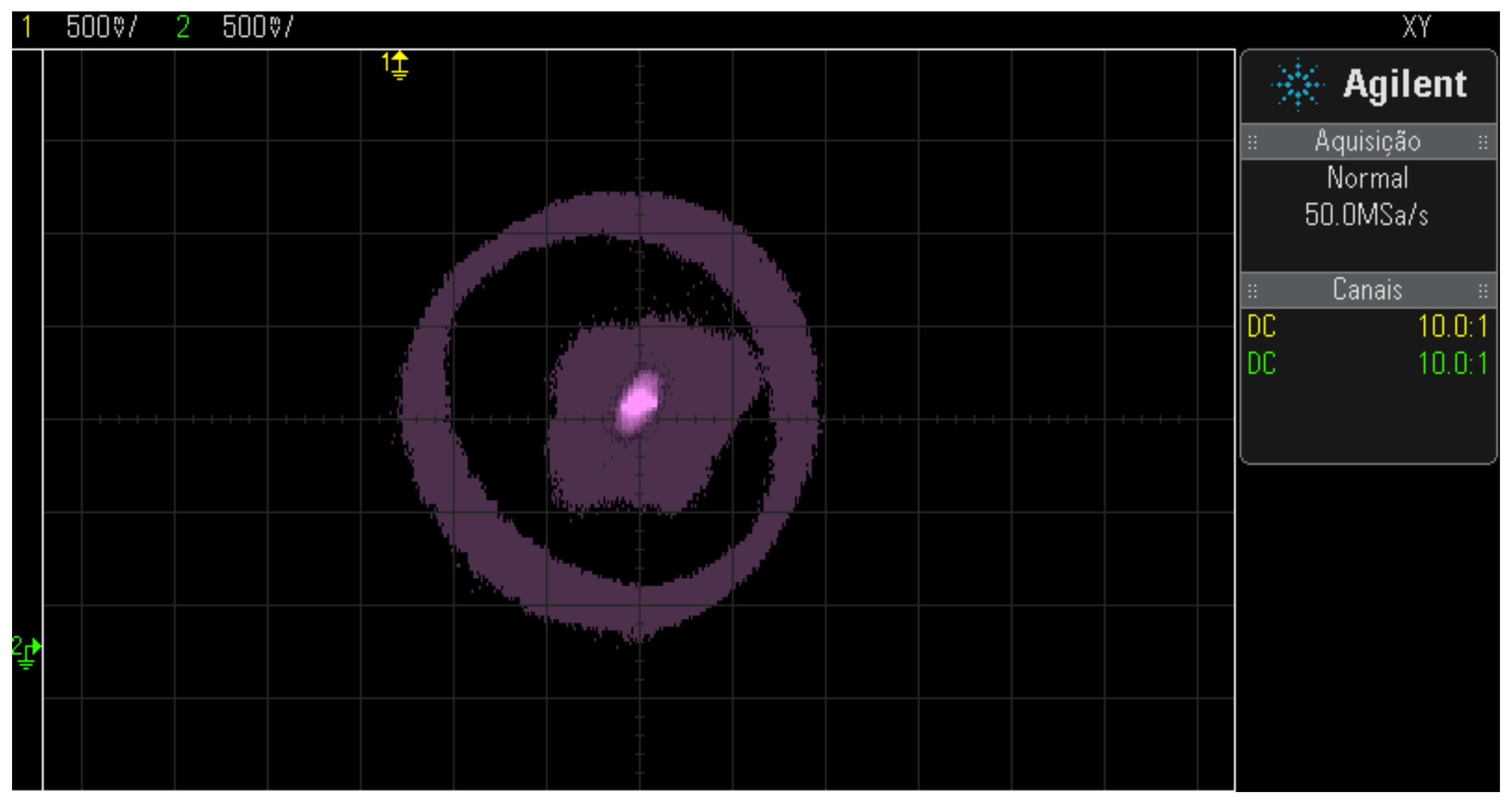
Figure 43.
Position control results with an area of dispersion from the rotor to the 45Hz drive.
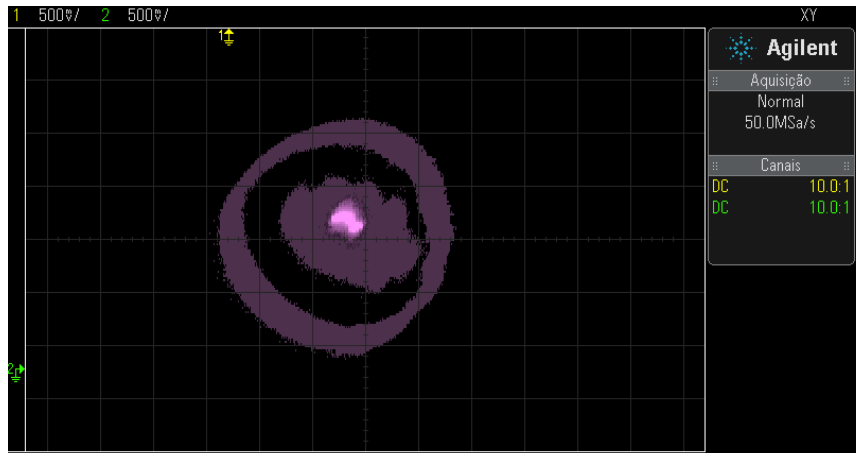
Figure 44.
Radial displacements of the X-axis driven at 60Hz.
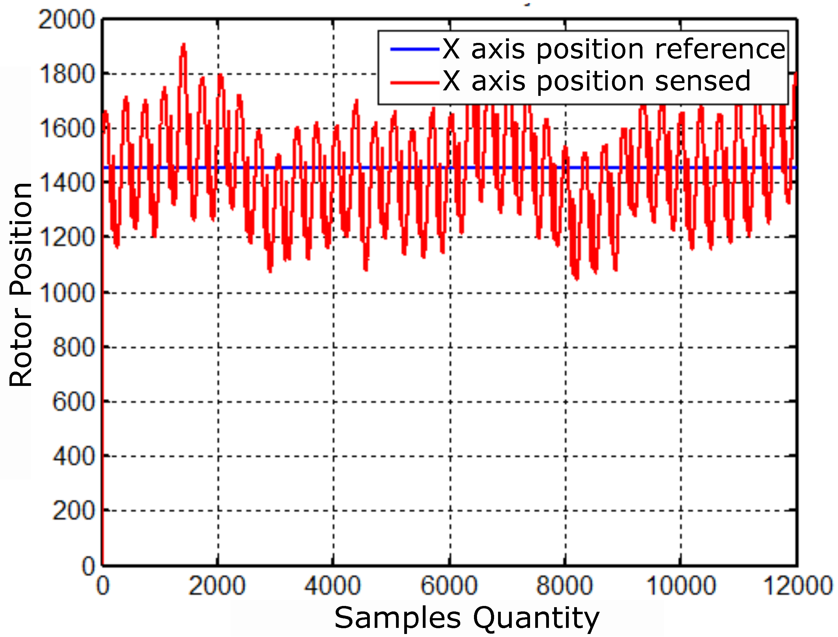
Figure 45.
Radial displacements of the Y-axis driven at 60Hz.
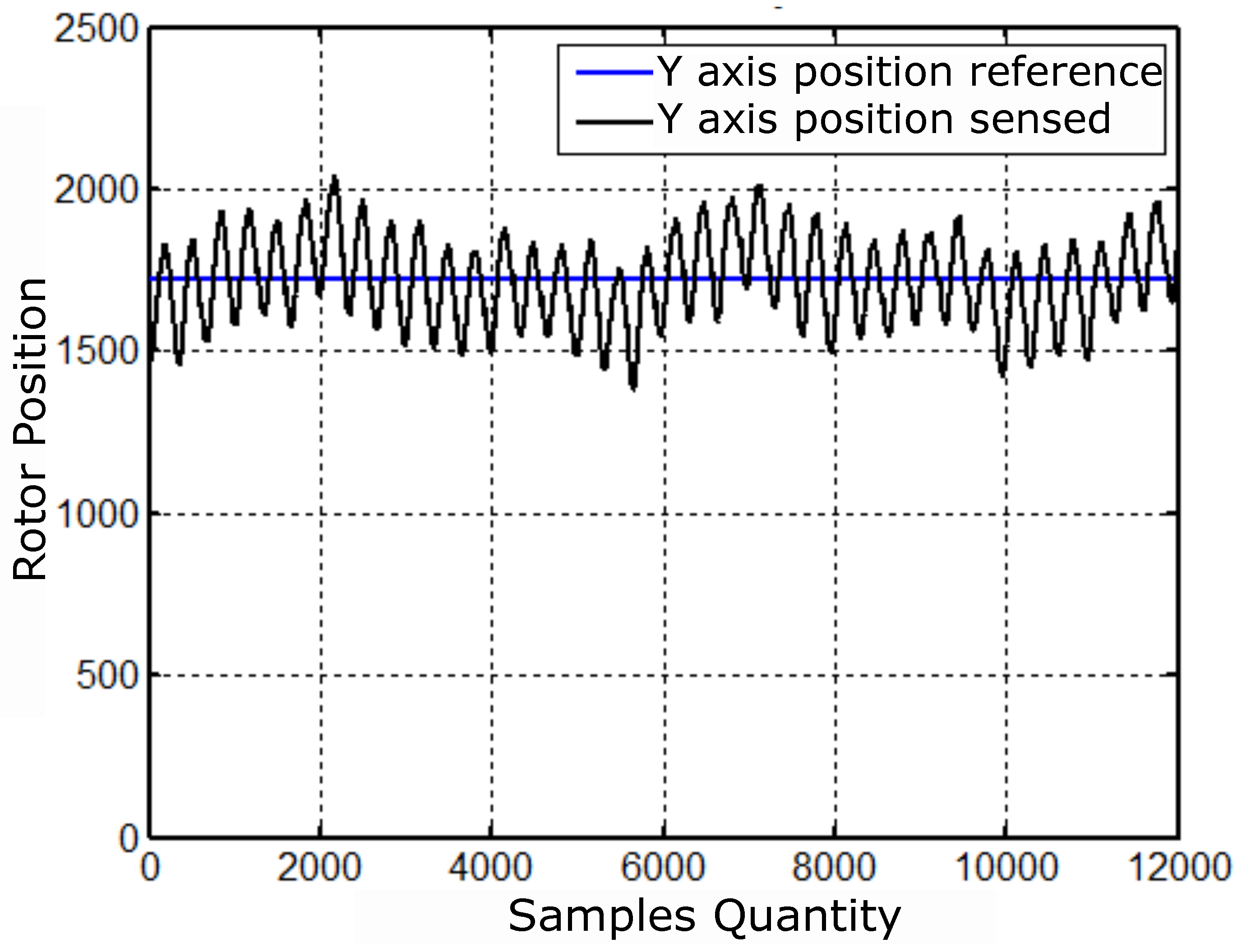
Figure 46.
Results referring to imposed, controlled and sensed currents.
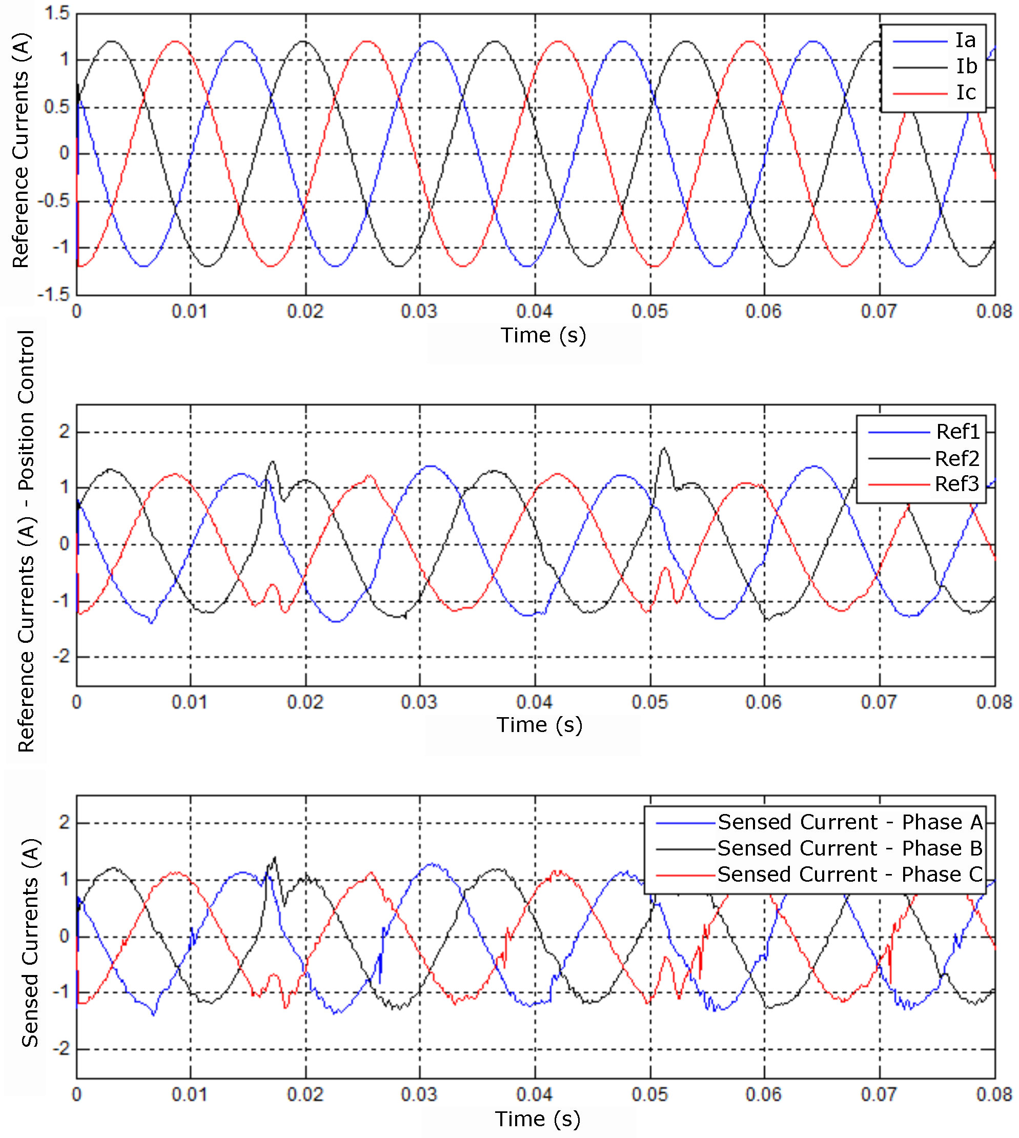
Figure 47.
(A) X position, (B) controller error, and (C) control signals.
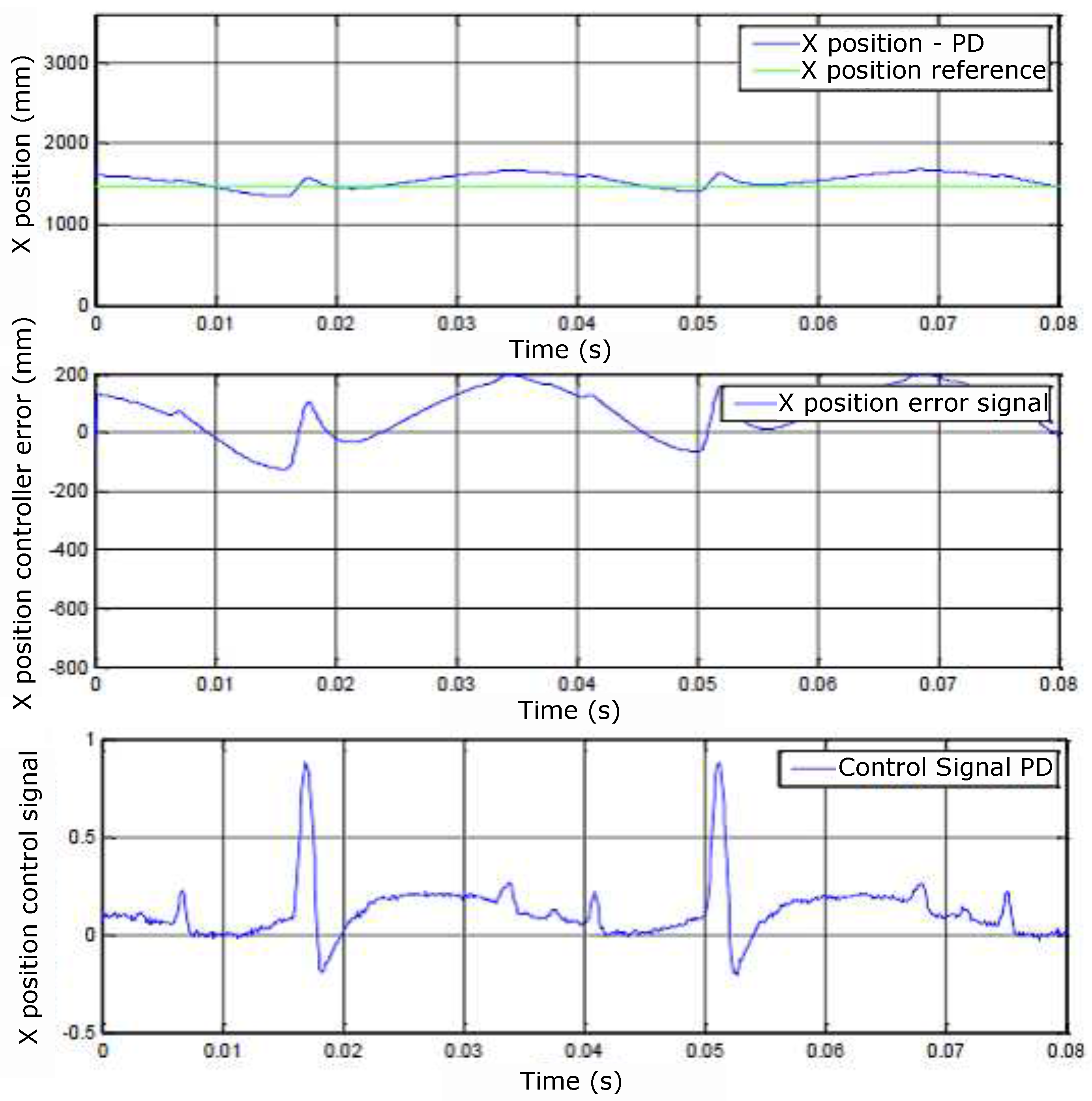
Figure 48.
(A) Y position, (B) controller error and (C) control signals.
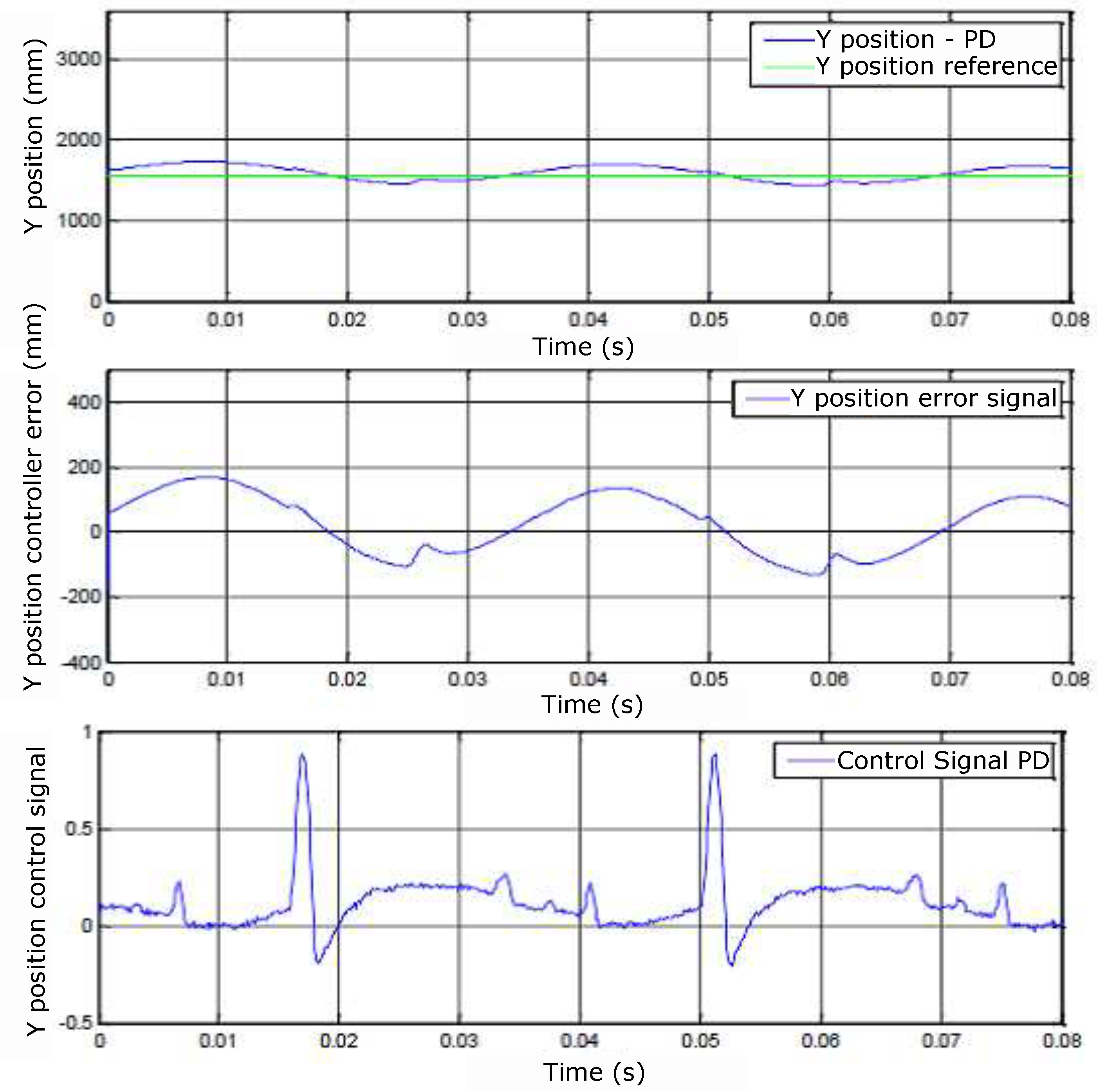
Figure 49.
Result of training, validation, and testing of the Neural Network.
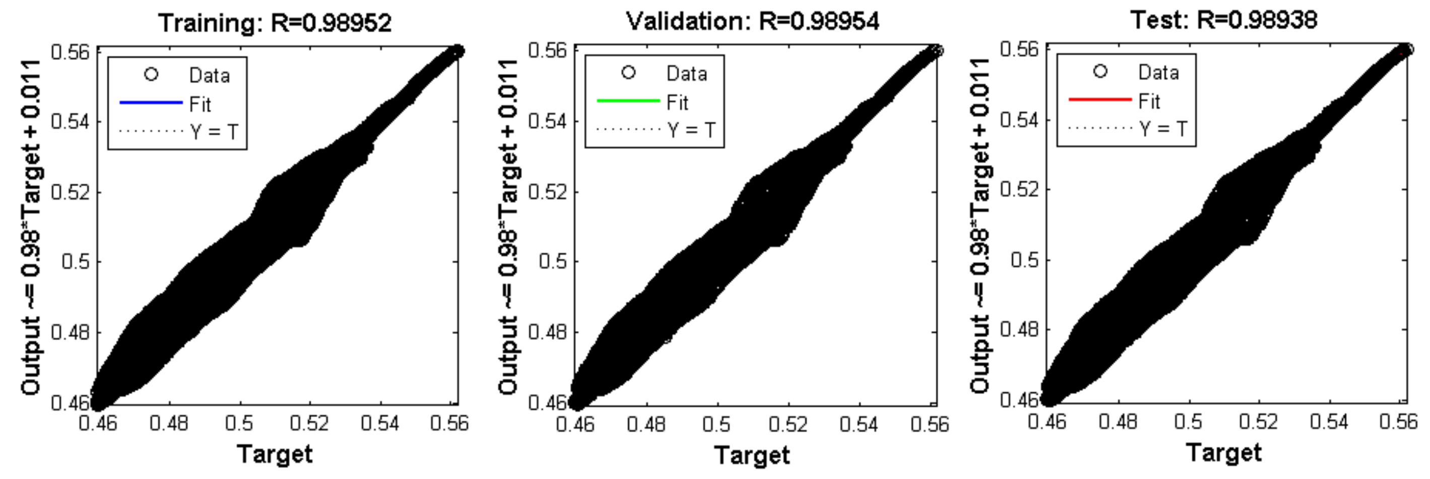
Figure 50.
Mean squared error for training with 104 epochs.
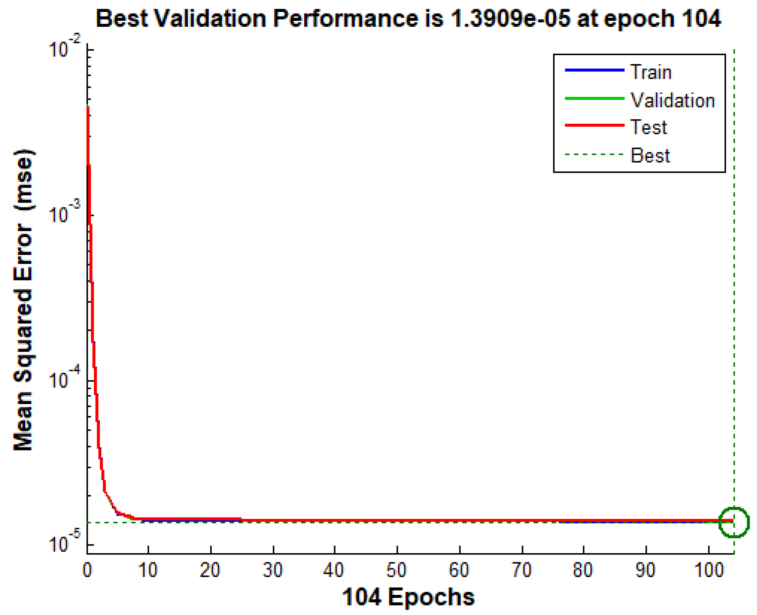
Figure 51.
Mechanical speeds and X and Y positions for step speed reference constant.
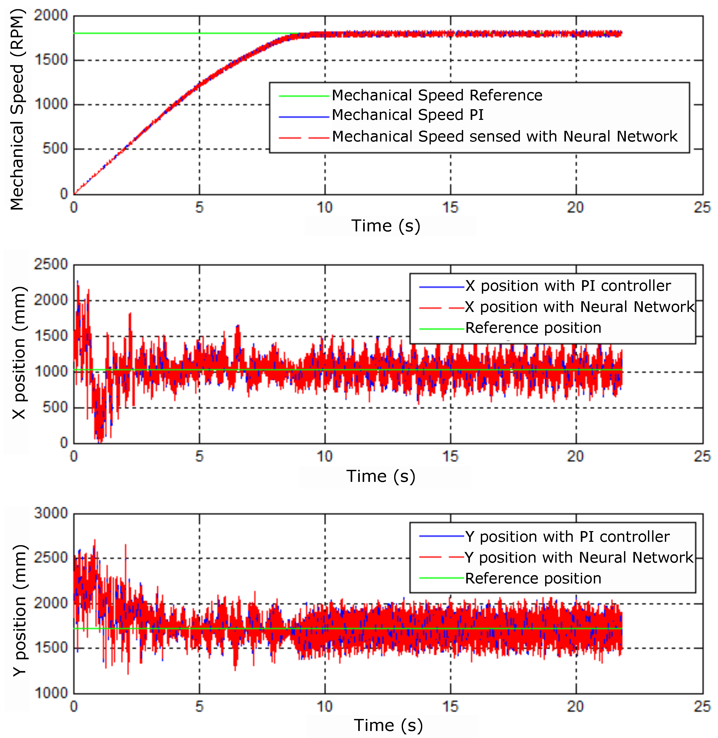
Figure 52.
PI and neural control signals for step speed reference.
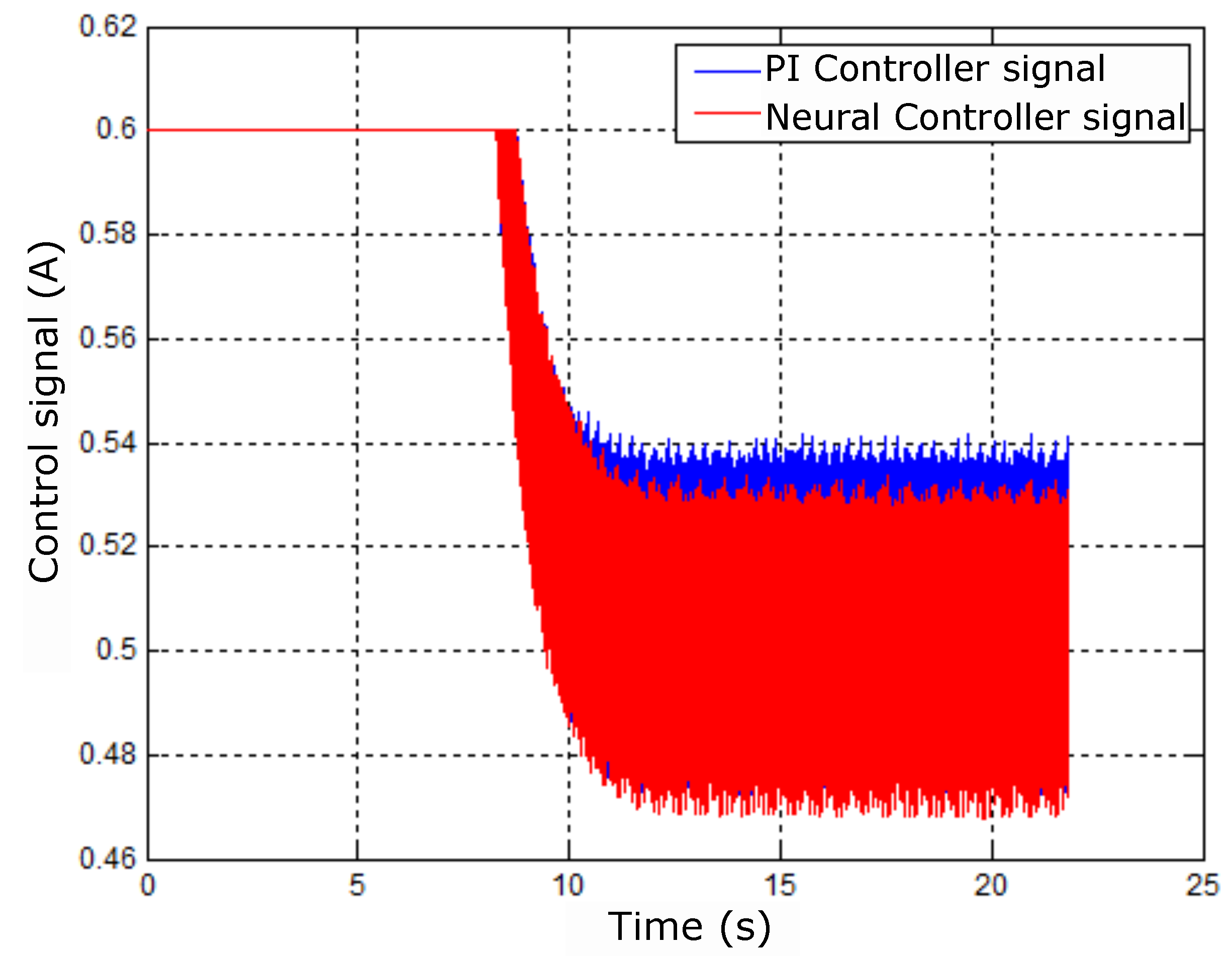
Figure 53.
Mechanical speed and X and Y positions for step speed reference.
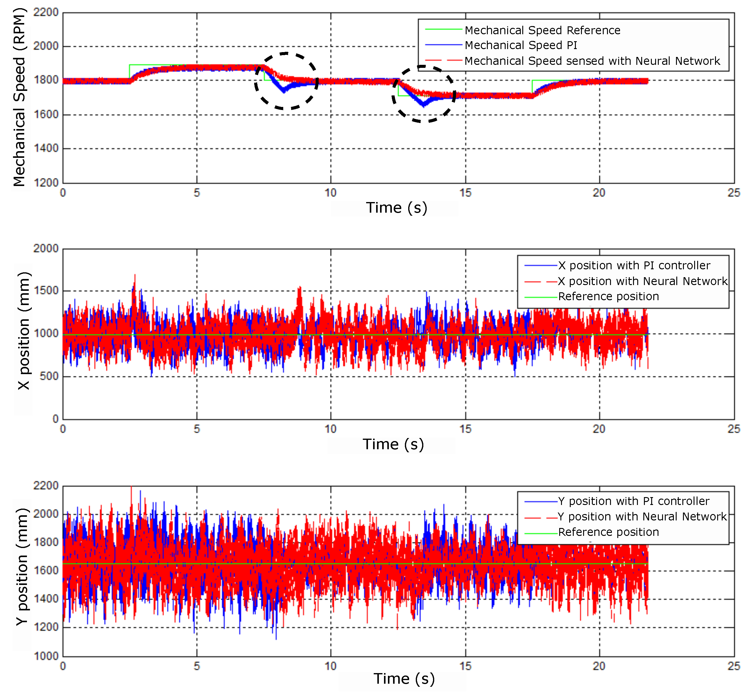
Figure 54.
Control signals for step speed reference.
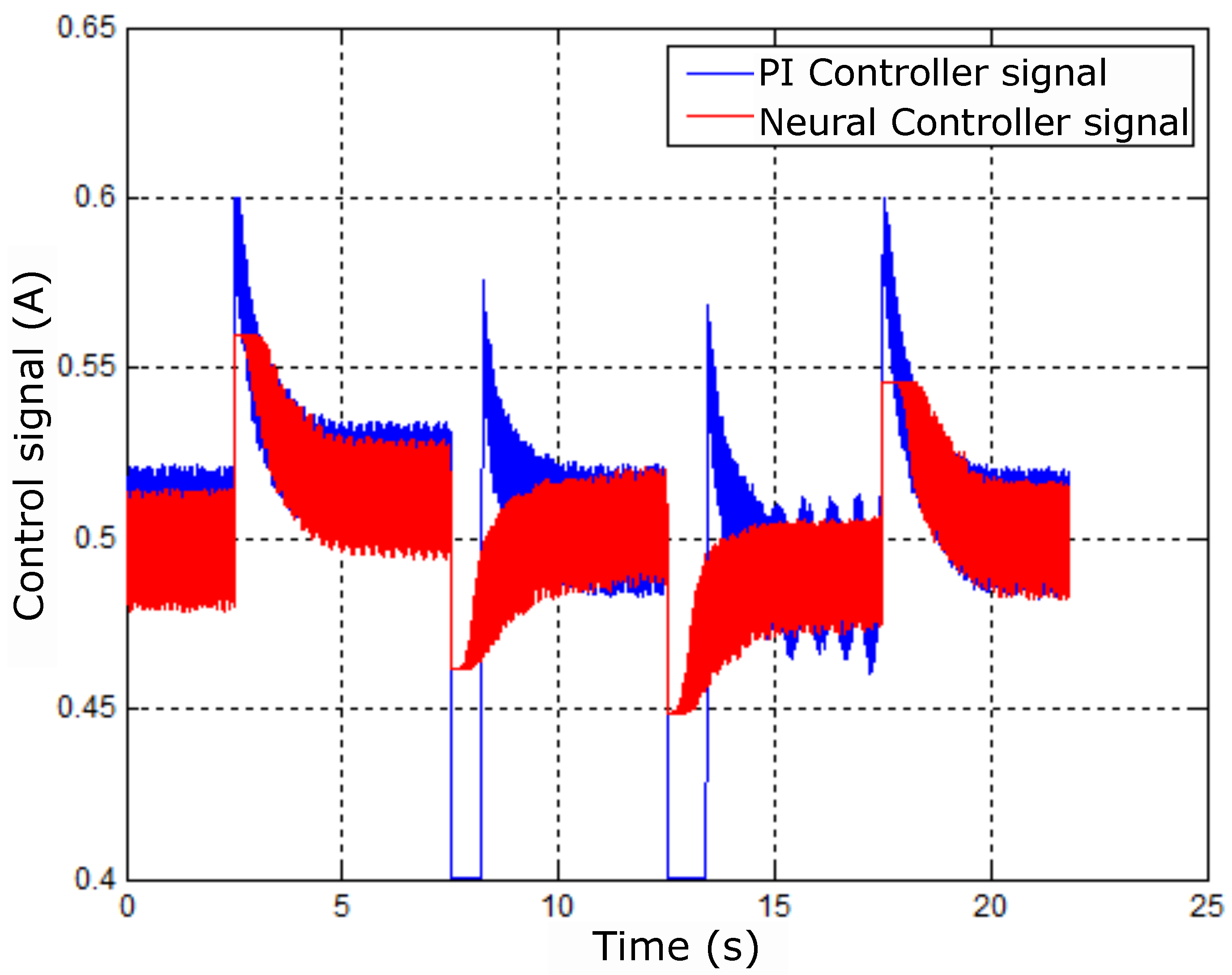
Figure 55.
Control error signals for step speed reference.
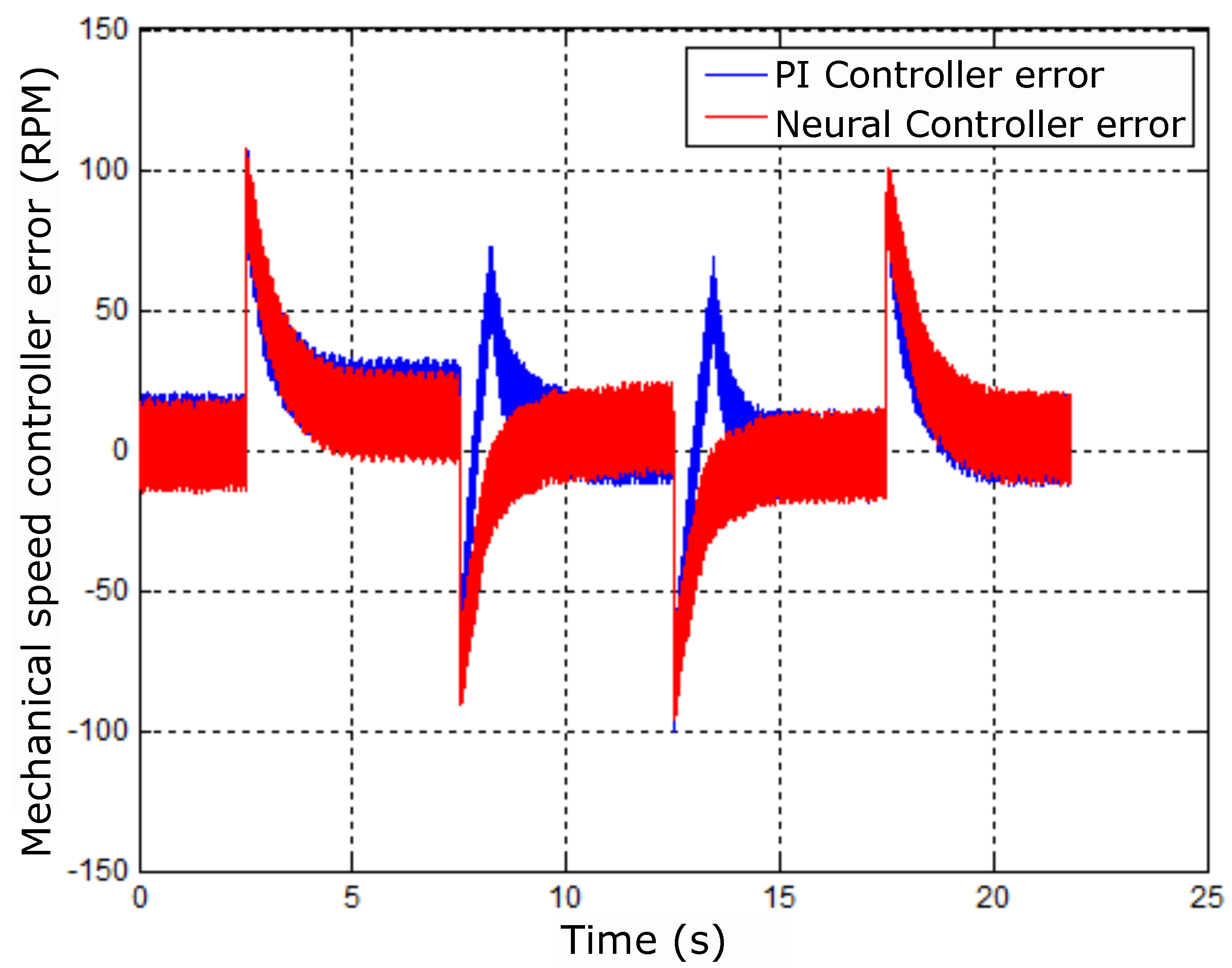
Figure 56.
Radial positioning diagrams for step speed reference.
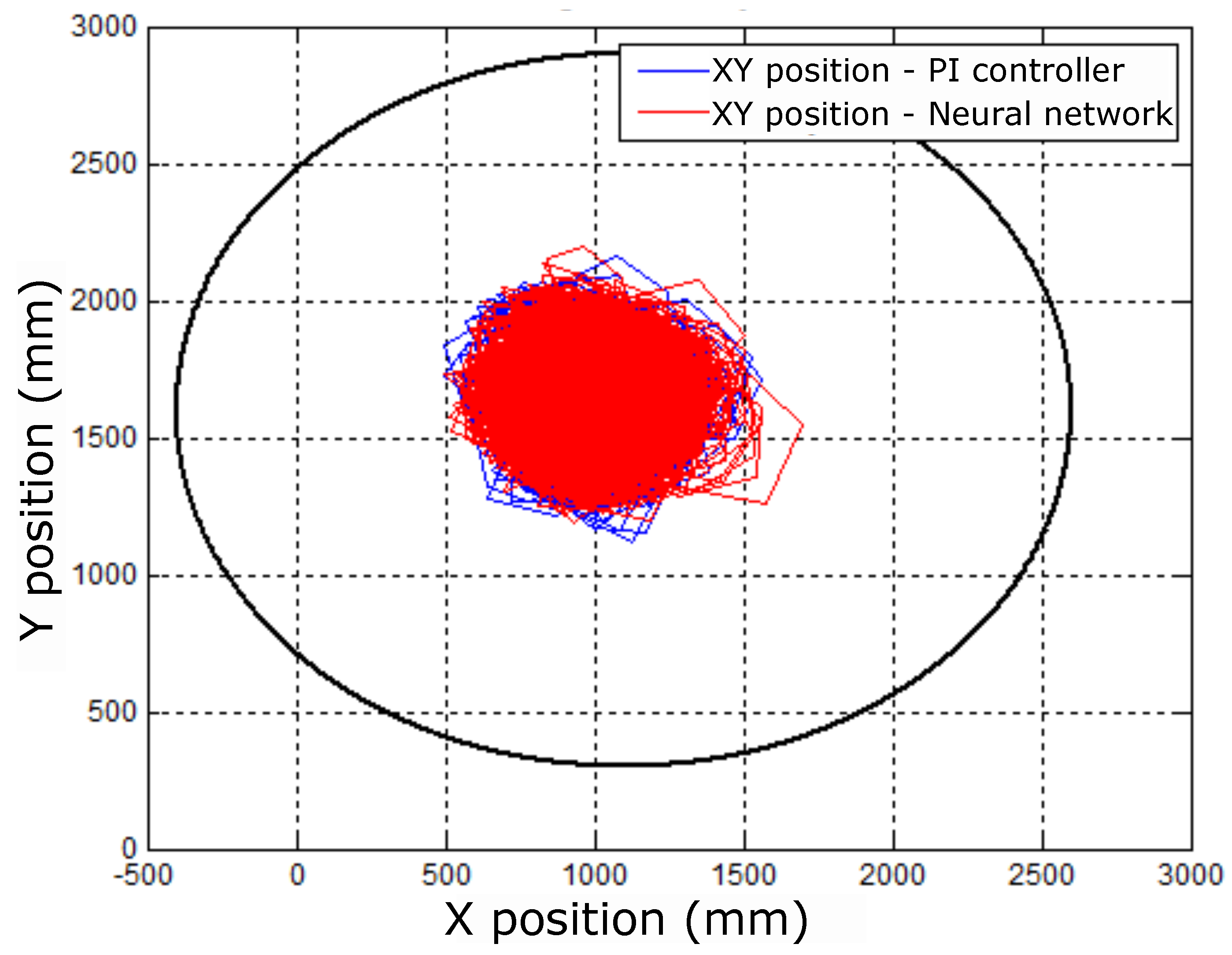
Figure 57.
Mechanical velocity measurement (A) PI control and (B) neural control.
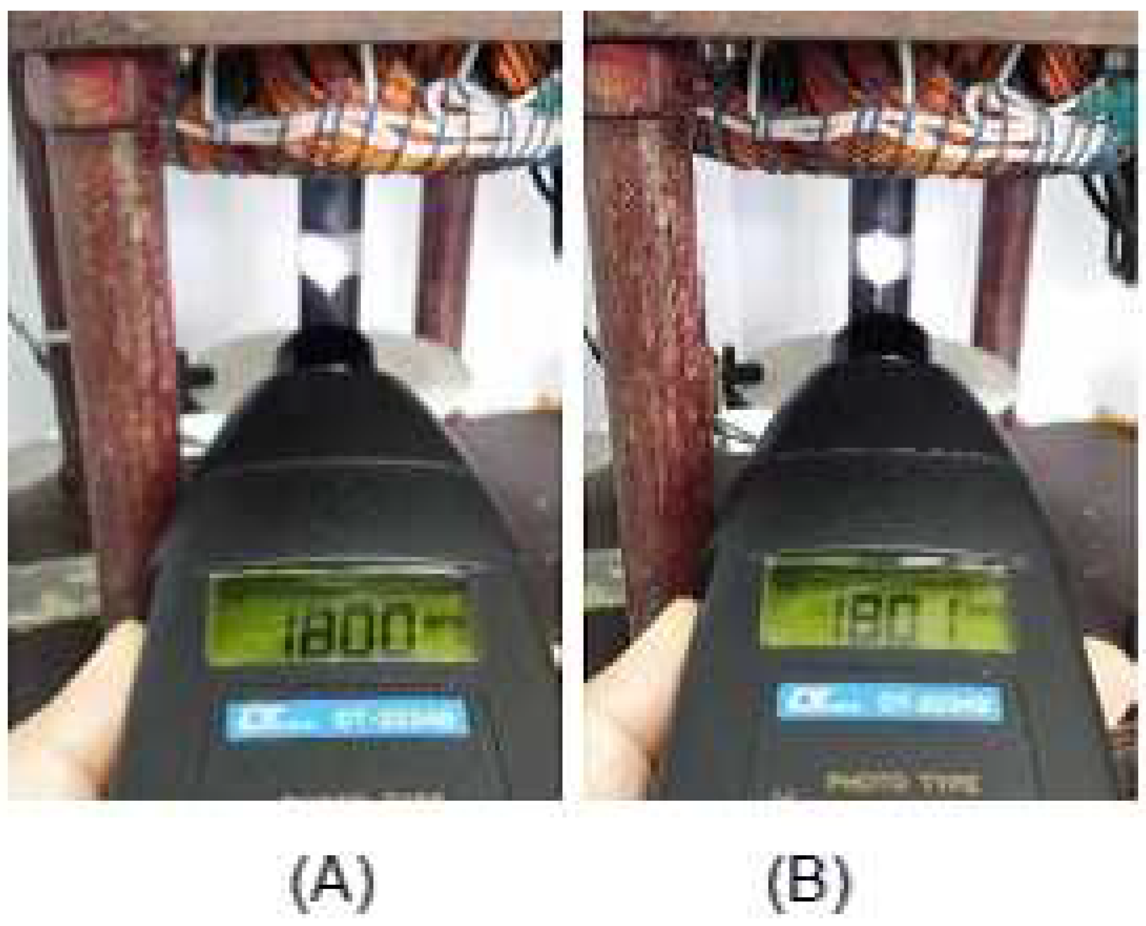

Table 1.
Engine Parameters and Characteristics.
| Symbols | Description | Values |
|---|---|---|
| Pnom | Rated power | 3.70 kW |
| Wmec | Rated Speed | 1715 RPM |
| Tnom | Rated voltage | 380 V |
| Np | Pole Pair Number | 2 |
| R1 | Stator Resistance | 1.182 |
| R2 | Rotor Resistance | 1.42 |
| J | Inertia moment | 0.00995 kg. |
| Ls | Stator Inductance | 6.56 mH |
| Lr | Rotor Inductance | 6.56 mH |
| Lm | Magnetization Inductance | 0.14 H |
| Core loss | 891.2 | |
| Gap size | 0.25 mm |
Table 2.
Parameters of PI Controllers used in tuning.
| PI | kpw | kiw | kpmM | kimM | kpimR | kiimR |
|---|---|---|---|---|---|---|
| (1) | 10.7 | 50 | 1 | 10 | 2 | 50 |
| (2) | 6 | 60 | 2 | 100 | 2 | 15 |
| (3) | 1 | 10 | 2 | 50 | 1 | 30 |
Table 3.
Controller Parameters.
| Controller Proportional-Full | Parameters | Values |
|---|---|---|
| Torque | KpmM | 1 |
| Torque | KimM | 100 |
| Magnetizing Current | KpimR | 2 |
| Magnetizing Current | KiimR | 50 |
Table 4.
ANFIS 1 Parameters.
| Pertinence functions | Epoach | training error | validation error |
|---|---|---|---|
| 2 | 50 | 0.0558002 | 0.00813261 |
| 3 | 150 | 0.0488926 | 0.00815185 |
| 3 | 300 | 0.0409925 | 0.01109080 |
| 5 | 500 | 0.00175787 | 0.00781050 |
Table 5.
ANFIS 2 Parameters.
| Pertinence functions | Epoach | training error | validation error |
|---|---|---|---|
| 2 | 50 | 0.00406290 | 0.00489893 |
| 3 | 150 | 0.00533958 | 0.7491140 |
| 3 | 300 | 0.00448118 | 0.3522810 |
| 5 | 400 | 0.00359959 | 0.3302490 |
Table 6.
Neural Network Parameters.
| Network Architecture | Multilayer Perceptron |
|---|---|
| Training type | Supervised - offline |
| Layers number | 3 |
| Input layer neurons | 3 |
| 1st hidden layer neurons | 10 |
| Output layer neurons | 1 |
| Training algorithm | Levenberg-Marquardt backpropagation |
| Learning rate | 5 |
| Epochs number | 841 |
| Training error | 9.4197 |
| Hidden layer activation function | Hyperbolic tangent |
| Output layer activation function | Linear |
Table 7.
Engine prototype parameters.
| Parameters | Values |
|---|---|
| Rated power | 1 Hp[hp] |
| Frequency | 60 Hz |
| Poles numbers | 4 |
| Rated voltage | 220/380 V |
| Rated current | 3.02/1.75 A |
| Empty current | 1.90 A |
| No load power | 160.00 W |
| Resistance | 7.38 Ohms |
| Stator Resistance per Phase | 0.73 Ohms |
Table 8.
Neural Network Parameters.
| Network Architecture | Multilayer Perceptron |
|---|---|
| Type of training | Supervised - offline |
| Number of layers | 3 |
| Input layer neurons | 2 |
| 1st hidden layer neurons | 10 |
| Output layer neurons | 1 |
| Training algorithm | Levenberg-Marquardt backpropagation |
| Learning rate | 5 |
| Epoch number | 104 |
| Training error | 1.3909 |
| Hidden layer activation function | Hyperbolic tangent |
| Output layer activation function | Linear |
Disclaimer/Publisher’s Note: The statements, opinions and data contained in all publications are solely those of the individual author(s) and contributor(s) and not of MDPI and/or the editor(s). MDPI and/or the editor(s) disclaim responsibility for any injury to people or property resulting from any ideas, methods, instructions or products referred to in the content. |
© 2024 by the authors. Licensee MDPI, Basel, Switzerland. This article is an open access article distributed under the terms and conditions of the Creative Commons Attribution (CC BY) license (http://creativecommons.org/licenses/by/4.0/).
Copyright: This open access article is published under a Creative Commons CC BY 4.0 license, which permit the free download, distribution, and reuse, provided that the author and preprint are cited in any reuse.


