
Submitted:
15 July 2025
Posted:
16 July 2025
You are already at the latest version
Abstract
This paper presents an experimental and computational investigation of novel, ejector-based, Coandă-surface-assisted tip leakage mitigation schemes. The predicted changes in the key performance metrics are presented after explaining the aerodynamic concept development for the novel tip geometries. The performance metrics are the stage total-to-total isentropic efficiency, tip-gap mass-flow rate, and a figure of merit based on rotor-exit total pressure. The schemes are based on direct geometric modifications to the turbine blade tip, effectively promoting an effective redirection of tip leakage fluid via specific channels. The proposed ejector channels operate in conjunction with strategically located Coandă surfaces to alter the path of the leakage fluid, promoting an effective leakage fluid delivery into the blade's wake. Multiple schemes are assessed, including single-ejector, single-ejector with “hybrid” squealer, double-channeled, and triple-channeled designs. The novel tip designs are evaluated computationally for the HP stage of the Axial Flow Turbine Research Facility AFTRF at Penn State University. Extensive experimental validation of the baseline flow computations for the large-scale HP stage is also presented. The current investigation identifies significant aerothermal improvements of the novel tip designs over the untreated flat tip. Upper-bound efficiency gains of 0.49% and mass flow reductions of 14.80% compared to an untreated flat tip of the large-scale, low-speed turbine test rig AFTRF are reported. Evaluation of the current tip designs in a high-speed turbine cascade environment with a transonic exit flow has also been completed. The detailed results from the high-speed investigation and heat transfer impact are in the process of being published. Implementation in the high-speed environment of the same design concept also returned non-negligible performance gains.
Keywords:
gas turbine
; HP turbine performance
; tip leakage mitigation
; Coanda flow
; fluid dynamic ejector
; RANS computation
; HPC
Introduction
A significant portion of the energy losses in a turbine stage is due to the gap between the system's rotating and stationary components, such as the gap between the turbine blade tips and the stationary casing. This gap, known as the tip clearance gap, allows the turbine stage to rotate free from interference, i.e., without rubbing. The tip clearance gap gives rise to the phenomenon of tip leakage flow, which is the flow of fluid through the thin passage made between the rotating surface of the blade tip and the inner wall of the stationary casing. The tip leakage flow accounts for about one-third of the total aerothermal losses in a turbine stage [1,2]. The consequences of tip leakage flow are manifested both thermally and aerodynamically, resulting in elevated tip temperatures and stage efficiency loss. After passing through the clearance gap, the tip leakage fluid emerges near the blade's suction side, where it separates and rolls into a strong vortex before mixing with the main passage flow. The formation of this vortex and its subsequent mixing with the mainstream further penalizes the fluid’s capacity to perform work on the turbine blade. This penalty has two parts: The first is the continuous non-participation of tip leakage fluid in power generation in the stage. The second is the viscous losses due to the formation and continuous dissipation of mean kinetic energy due to the tip leakage vortex. The tip leakage flow is also detrimental from a thermal standpoint [3]. In gas turbines, the flow expanding in a turbine is virtually the same temperature as the flow exiting the combustor. Therefore, the non-participation of the tip leakage fluid in work extraction means the tip leakage fluid retains its total temperature, resulting in high thermal loads on the tip of the turbine blades [1,4]. The high temperature leakage fluid usually results in charring and related structural detriment over time via material oxidation [5,6,7]. The mitigation of tip leakage flow and subsequent reduction of tip leakage vortex strength has been one of the main thrusts of recent research efforts since the mid-1980s. Researchers have published many initiatives to modify the untreated leakage flow pattern from a flat tip to provide more desirable aerothermal loss figures across the stage. A computational study conducted in the late 90s by Ref. [8] showed that , a measurable reduction in mass flow rate of about 14% through the tip gap was possible. Ref. [9] explored the aerodynamic performance of various partial squealer designs experimentally at different coverages. Their results concluded a non-negligible performance improvement for suction side squealers. In Ref. [10], six different squealer tip geometry arrangements were studied experimentally in a linear cascade. Similar to the findings in Ref. [9], they concluded that a squealer on the suction side provides a reduced leakage mass flow rate compared to that of the pressure side squealer or the mid-camber squealer. Similarly, Ref. [11] experimentally investigated flat and squealer tip geometries. Their results found that squealer tip cases provide lower aerodynamic losses than the flat tip. Recent studies, such as the work carried out by Ref. [12], expanded investigations on the concept of squealer geometries by experimentally investigating “stepped” squealers with differing pressure and suction side height rims. Their results did not show much difference in loss reduction from stepped to conventional cavity squealers. As an alternative tip leakage desensitization technique, pressure and suction side tip platform extensions were experimentally investigated by Ref. [13]. They found that implementing a pressure side tip platform extension provided better total pressure retention of at the tip region of the rotor exit compared to an untreated flat blade. The experimental investigations conducted by Ref. [14] produced similar conclusions for pressure side extensions. They also found that PS winglet-type extensions weaken the strength of the tip leakage vortex. In Ref. [15], computational studies were conducted on pressure-side winglets, suction-side winglets, suction-side squealers, cavity squealers, and inclined pressure-side squealers, where the inclined pressure-side squealer was predicted to improve turbine efficiency. Ref. [16] studied additional tip platform-based configurations where full coverage winglets on turbine blades were investigated. They reported a reduction in aerodynamic losses within a critical winglet width. Refs. [17] and [18] performed experimental and numerical studies on the aerodynamic performance of SS winglets, and found that implementing SS winglets is beneficial for aerodynamic performance. Full-covered winglets were studied by Refs. [19,20,21,22,23], where it was found that full-covered winglets are beneficial for leakage flow reduction, thermal load reduction, and cooling enhancement. Additional studies involving squealer, platform extensions, and related tip leakage. mitigation schemes can be found in References from [24] to [25]. Ref. [26] studied the aerothermal performance of multi-cavity blade tip configurations; they found that the multi-cavity approach improves thermal performance. A study in Ref. [27], aimed to reduce the tip leakage vortex strength by experimenting with vortex generators mounted on the turbine blade's suction side. Their results suggested that with further studies, an optimal location, size, and orientation of the TLIs could prove to be an effective loss mitigation scheme for tip leakage flows. Additional studies to counteract the detrimental effects of the tip leakage vortex were carried out by Ref. [28], where the implementation of a slit in the turbine blade was tested experimentally. Their studies indicated that the implementation of the blade slit produced a measured positive aerodynamic effect on the passage. In the area of casing treatments, Ref. [29] numerically studied the effect of circumferentially grooved casing treatments in a linear turbine cascade. Three circumferential groove configurations were considered: square, diverging, and converging. Their results predicted a reduction of leakage mass flow rate and reduced the tip leakage vortex size. Research efforts in Refs. [30,31,32], investigated the aerodynamics of nonuniform tip clearance in turbines, which largely resulted in a reduction in aerodynamic performance. Several researchers investigated nonpassive tip leakage mitigation techniques, such as blowing coolant air into the tip gap from the blade tip. An experimental study of this nature was performed in Refs. [33,34], where it was found that with the strategic placement of coolant holes, a measurable reduction in the leakage vortex's size and strength was observed. Ref. [35,36] presented similar numerical and experimental studies on coolant injection effects on tip leakage flow. Recent advancements in turbine tip leakage mitigation have increasingly leveraged algorithmic optimization techniques to refine tip geometries for improved aerodynamic performance. These methods utilize optimization schemes to systematically explore and identify optimal tip shapes that reduce leakage losses and enhance overall stage aerothermal performance. Recent studies have applied these techniques to both flat tip and squealer tip configurations. The study in [37] employed an algorithmic free-form deformation technique on a squealer tip, which produced an optimized squealer geometry which enhanced the stage efficiency by 0.42% and reduced the tip gap mass flow rate measurably. Reference [38] compares the aerothermal performance of two novel algorithmically carved 3D turbine rotor tips against conventional flat and squealer tip designs. Their simulations predicted improvements in heat transfer and aerodynamic loss compared to flat and squealer tip designs. In [39], algorithmic tip carving was implemented to optimize tip shapes for multi-cavity squealer-like tips. The optimized tip geometries were evaluated through numerical simulations demonstrating improvements in heat transfer and leakage flow control compared to conventional designs. The study in [40] explored a novel blade tip carving approach to reduce tip leakage losses and heat transfer in axial turbines using a genetic algorithm. Their results show that carved blade tips significantly reduce total pressure loss and leakage mass flow, though achieving both optimal aerodynamic and thermal performance simultaneously remains a design trade-off. The study in [41] employed a neural network to optimize squealer cavity tip geometry in a transonic high-pressure turbine, identifying an optimal squealer height, squealer width, and gap height that minimize leakage flow and heat transfer.
Ejector-Based Tip Leakage Mitigation Concept
The primary goal of this study is to demonstrate the viability of a novel turbine tip leakage mitigation scheme using the combined concepts of 'fluid dynamic ejector' and 'Coandă surfaces'. Multiple streamwise channels are also considered. Diverting the turbine tip leakage fluid using the operating principles of conventional fluid dynamic ejectors [42] is pursued as a tip leakage mitigation method. The mitigation is achieved by designing a flow environment in the tip gap promoting effective entrainment and ejection of tip leakage flow into a channel connected to the wake of the airfoil. This approach reduces the leakage mass flow rate and weakens the tip leakage vortex in the maınstream. A reduction in the strong interaction of the counter-rotating tip vortex and upper passage vortex system results in measurable turbine efficiency gains near the tip region. Figure 1 shows a 'fluid dynamic ejector' as a device attracting the tip leakage fluid into an ejector channel driven by a motive fluid accelerating into a converging ejector channel. After acceleration of the 'motive fluid' into the converging channel, the pressure in the channel drops measurably compared to that of the motive fluid at the entrance. The reduced pressure in the middle section of the ejector channel results in the suction of the fluid approaching this section from any opening at the periphery of the channel. Figure 2 depicts the implementation of a 'fluid dynamic ejector' on a turbine blade tip. The leakage fluid enters the tip gap from the pressure side corner of the tip platform as seen in Figure 2.a. The resulting tip vortex forms near the suction side corner of the airfoil in the mainstream. The 'fluid dynamic ejector' constructed on the tip platform is shown in Figure 2.b. The 'motive fluid' enters the converging channel near the airfoil stagnation point with a relatively high stagnation pressure. As the 'motive fluid' accelerates in the converging streamwise channel, it attracts a portion of the leakage flow approaching from the pressure side corner. The result is a reduction in the leakage mass flow rate exiting to the mainstream flow near the suction side corner. A smaller and weaker tip vortex forms compared to the flat tip as depicted in Figure 2.a. The effective entrainment of a portion of the tip leakage fluid into the ejector channel is analogous to the flow conditions existing in conventional 'fluid dynamic ejectors' as shown in Figure 1.
Ejector-Based Tip Leakage Mitigator Designs
Eleven ejector-based blade tip concepts are designed and analyzed. The new designs are computationally studied in the Axial Flow Turbine Research Facility (AFTRF) at the Pennsylvania State University. The AFTRF is a single-stage, large-scale, rotating turbine test rig designed with similar loading characteristics to the E3 engine design from NASA/GE [43]. The basic geometry of the turbine blades in the facility is presented in Figure 3. The eleven ejector-based tip leakage mitigator designs are shown in Figure 4, Figure 5, Figure 6, Figure 7, Figure 8, Figure 9, Figure 10, Figure 11, Figure 12, Figure 13, Figure 14 and Figure 15. This selection of concepts is based on critical junctures in the design evolution, which employ key geometric changes to the turbine blade that are computationally predicted to produce measurable aerodynamic improvements. A cross-section normal to the blade tip platform, at 55% axial chord is also presented in each design. A tip gap of t/h=0.8 % is used for the baseline geometry and the eleven new leakage mitigator designs.
Ejector Baseline (EB): The Ejector Baseline (EB) concept presented in Figure 4 is the backbone of the contributions made in this work. The EB geometry is generated from numerous exploratory studies based on the design philosophy of ejector-based transport and is designed to operate on the surrounding flow field advantageously. The geometric design and location of the inlet, channel, and ejection site of the Ejector Baseline (EB) are seen in Figure 4. The depth of the channel is selected to be 4 mm.The location of the inlet is chosen to be on the suction side of the leading edge (LE) and is approximately 19 mm in width. The channel rapidly converges to about 4 mm at the location of the maximum static loading difference (about 45% axial cord,) before gradually converging to a width of approximately 2.5 mm at the ejection site at the trailing edge (TE).
Ejector Coandă (EC): The Ejector Coandă (EC) concept is presented in Figure 5. This design features a rounding of the near-PS channel wall of the Ejector Baseline (EB), creating a strongly convex Coandă-surface. The Coandă effect is the tendency of a fluid stream to stay attached to a surface of any form to entrain fluid from the surroundings so that a region of lower pressure develops. It is named after Henri Coandă, who was the first to recognize the practical application of the phenomenon in aircraft design,[44]. Adding a well-rounded convex surface improves the entrainment of the tip leakage fluid into the ejector channel, [45]. This Coandă-surface has an initial radius of 3 mm at the LE of the blade, which linearly diminishes to 0 mm as the channel wall runs down the axial chord of the blade.
The Ejector Coandă-I (ECI): The Ejector Coandă-I (ECI) concept presented in Figure 6 is identical to the Ejector Coandă (EC) design except that a 1 mm linear incline is placed on the near-SS ejector channel wall, which terminates at about 60% of the blade axial cord.
The Ejector Coandă-I5 (ECI5): The Ejector Coandă-I5 (ECI5) concept is shown in Figure 7. In this design, the channel depth of the Ejector Coandă-I (ECI) is increased by 1 mm, resulting in the total depth of the ejector channel being 5 mm.
The Ejector Coandă-I5n (ECI5n): The Ejector Coandă-I5n (ECI5n) concept is presented in Figure 8. The Ejector Coandă-I5 (ECI5) near-tip edge of the PS of the blade is fitted with a circular notch. The circular notch feature is approximately 1.5 mm in diameter and runs along the entire axial cord of the pressure side of the blade. The notch is implemented to reduce the incoming leakage mass flow rate into the tip gap.
The Ejector Coandă-I5n Hybrid Squealer (ECI5n-HS): The Ejector Coandă-I5n Hybrid Squealer (ECI5n-HS) concept is presented in Figure 9. The unmodified flat surface of the Ejector Coandă-I5n (ECI5n) is manipulated. This surface is transformed into a miniaturized squealer, which for this research, is called a hybrid squealer, with a rim thickness of 2 mm and a cavity depth of 5 mm.
The Ejector Coandă-I5n Hybrid Ejection Squealer (ECI5n-HES): The Ejector Coandă-I5n Hybrid Ejection Squealer (ECI5n-HES) concept is shown in Figure 10. The TE end of the hybrid squealer cavity in the Ejector Coandă-I5n Hybrid Squealer (ECI5n-HS) is opened to a thin passage that connects the cavity of the hybrid squealer to the main ejector channel. An enlarged view of the thin passage connecting the hybrid squealer and the main ejector channel is presented in Figure 16.
The Ejector Coandă-I5n Optimized Hybrid Ejection Squealer (ECI5n-OHES): The Ejector Coandă-I5n Optimized Hybrid Ejection Squealer (ECI5n-OHES) concept is presented in Figure 12. A near-PS Coandă-surface and a near-SS linear incline are implemented on the walls of the hybrid squealer cavity of the Ejector Coandă-I5n Hybrid Ejection Squealer (ECI5n-HES). This modification is similar to the changes made to the ejector channel between the Ejector Baseline (EB) concept and the Ejector Coandă-I (ECI) concept. The radius of the Coandă-surface varies linearly from 2 mm at the LE end of the near-SS wall of the hybrid squealer cavity to 0 mm at the TE end of the near-SS wall of the hybrid squealer cavity. In addition, the near-PS wall of the hybrid squealer cavity is inclined to a distance of 1.5 mm at the tip surface.
The Dual Ejector Coandă-I5n (D-ECI5n): Instead of a hybrid squealer, a second ejector channel is implemented in this design as shown in Figure 13. A channel of similar dimensions to the main ejector channel is created adjacent to the main ejector channel. This new ejector channel features a Coandă-surface with a radius that varies linearly from 2 mm to 0 mm starting at the LE end of the near-PS wall of the second ejector channel. Additionally, the second ejector channel is connected to the main ejector channel near the TE edge with a thin passage identical to the geometry used to create the hybrid squealer ejector channel in the Ejector Coandă-I5n Hybrid Ejection Squealer (ECI5n-HES) concept. The thin passage arrangement is similar to that of (ECI5n-HES) as depicted in Figure 16.
The Dual Ejector Coandă-I5n Hybrid Squealer (D-ECI5n-HS): In this design, the unutilized surface above the second ejector channel in the Dual Ejector Coandă-I5n (D-ECI5n) is used to implement an even smaller hybrid squealer as presented in Figure 14. The rim thickness of this hybrid squealer is 2 mm.
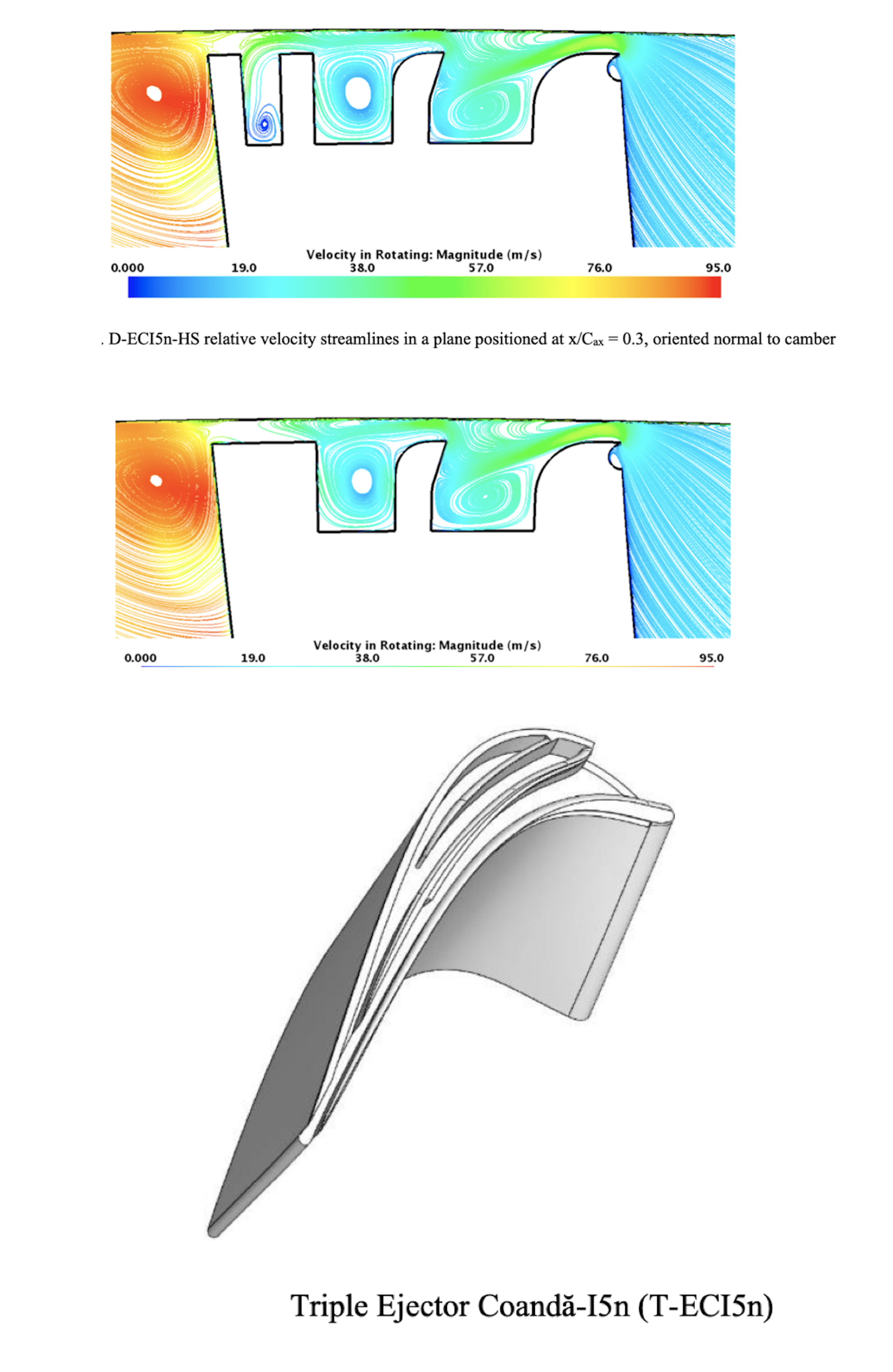
The Triple Ejector Coandă (T-ECI5n): In this design, shown in Figure 15, the TE end of the hybrid squealer cavity in the Dual Ejector Coandă-I5n Hybrid Squealer (D-ECI5n-HS) is opened to a thin passage that connects the cavity of the hybrid squealer to the second ejector channel, which then connects to the main ejector channel. In addition, the third ejector channel features a Coandă-surface radius that varies linearly from 2 mm to 0 mm starting at the LE end of the near-SS wall of the third ejector channel.
Parametric Equations of Ejector Channel Contours: Parametric curves in a cartesian coordinate system centered at the TE of the AFTRF blade tip form the contours of the Ejector Baseline (EB) channel and the Dual Ejector Coandă-I5n (D-ECI5n) channel. The channel geometries are mapped by a position vector parameterized in terms of the axial distance in millimeters from the trailing edge of the blade tip, for the current ejector designs. The nonzero z-components are due to the inherent three-dimensionality of the AFTRF's blade tip geometry; however, the essential geometry of the ejector channel is captured two-dimensionally on the x-y plane. Details of this parametric model are described in [46]. The aerothermal analysis of eleven novel blade tip concepts presented in this work is carried out in two phases: computations under AFTRF largescale test rig conditions and experimentation in the same rotating rig.
Computational Model of Aftrf
Computational Model and turbulence treatment: The AFTRF computational predictions for the development of Coandă-Ejector based tip leakage mitigators are performed using STAR-CCM+, a Reynolds-Averaged Navier Stokes Equations (RANS) based finite-volume solver. The maximum measured Mach number observed in the AFTRF is about 0.3. Therefore, a steady incompressible RANS solver was invoked for the computational effort. The interface between the stationary NGV and rotor with constant angular speed is a mixing plane. STAR-CCM+ implements the conservation laws in differential form for an infinitesimal control volume to solve six flow quantities everywhere in the domain: three mean velocity components , mean density mean thermodynamic pressure , and temperature . The standard (k-ε) turbulence model is implemented. Further details of the computational effort are documented in [47] and [46].
Experimental validation of turbine stage computations: The experiments are carried out to validate the stage loading characteristics and the three-dimensional flow features, including tip vortices, passage vortices, horseshoe vortices, airfoil wakes and boundary layers. The computational domain constructed for this research effort is a 1:1 reconstruction of the HP turbine stage of the Axial Flow Turbine Research Facility (AFTRF) at Pennsylvania State University. This facility is a large-scale, rotating turbine stage, operating at 1330 RPM as shown in Figure 17. A detailed description of this experimental facility can be found in Refs. [48] through [49]. The large-scale turbine stage has design similarities to NASA/GE E3 "Energy Efficient Engine" [43] regarding the loading characteristics. The HP stage has 23 stationary nozzle guide vanes and 29 turbine rotor blades. Although rotor blade loading distributions of the E3 design are well emulated, the maximum flow Mach number reached in this large-scale facility stage is about 0.3. This open-circuit, ambient-flow facility consisting of a single high-pressure (HP) turbine stage is driven by four-stage axial flow fans connected in series. The power generated at the rotor of the turbine test rig is usually between 30 HP and 200 HP, and the stage temperature drop is less than 10 o K. The work produced in the stage is absorbed by a water-cooled eddy current brake, regulating the rotational speed of the rotor within +/- 1 rpm. A schematic of. An aerodynamically designed exit throttle is used to adjust the pressure rise across the stage. The four axial flow fans produce a pressure drop for the turbine test section of 74.7 mm Hg with a volumetric flow of approximately 11.4 kg/s. Table 1 and Table 2 summarize the main AFTRF performance parameters and design parameters, respectively.
Instrumentation and Data Acquisition: The measured inlet velocity profile is presented in Figure 18 together with turbulent kinetic energy, [50]. These two profiles are used in all RANS computations throughout this study. Experimental data relevant to the operation of the stage are also obtained by measuring total pressure on a plane normal to the axis of rotation, at the inlet and exit of the rotor as shown in Figure 23.(b). Stage inlet and exit total pressure relative to the ambient pressure is measured using an electronic pressure scanner unit ESP-32 from Pressure Systems Inc. The exit probe is located 25.4 mm downstream of the rotor at mid-span, measured from the trailing edge of the blade tip. The stage inlet probe is located one chord upstream of the NGV leading edge at mid-span. The exit probe head is aligned with the absolute rotor exit flow which has an angle of 25.16 o measured from the axial direction. The
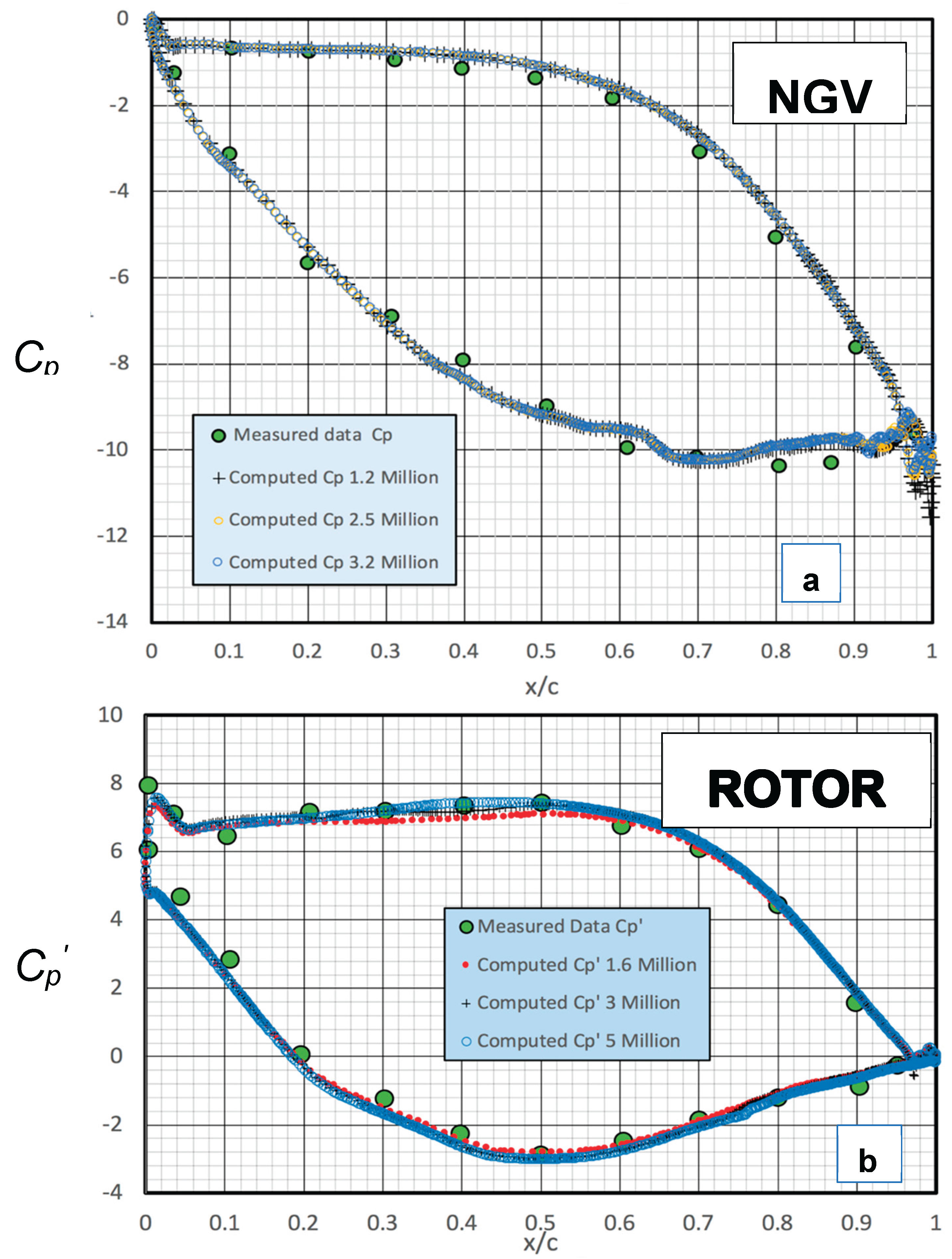
Measured stage loading : The static pressures on the mid-span airfoil section of the NGV and rotor blade were obtained from flush-mounted static holes. An ESP-32 pressure scanner electronically multiplexed the NGV static pressure data in the stationary frame of reference. The scanner has a built in A/D and provides a digital output for direct interfacing to the data collection system. The pressure scanner connected to the mid-span static holes of the rotor is in the rotating freme of reference, spinning at 1330 rpm. The pressure scanner unit is located in the rotating instrumentation drum of the AFTRF, Figure 17 at a radial position 2 inches away from the axis of rotation to minimize the signal error due to the rotation of the miniature pressure transducer. Although this transducer scans 32 individual pressure channels, its pressure output is transmitted through a 15 channel digital TTL interface. The digital output of the ESP-32 pressure scanner is passed through a brush-and-coin type conventional slip-ring unit without noise and signal loss. The following equation defines the static pressure coefficients measured on the mid-span of the NGV airfoil:
where PNGV is the local static pressure measured on the airfoil surface at mid-span, P1 is the NGV inlet static pressure and Vx1 is the axial component of the NGV inlet velocity at mid-span. Pressure measurements in the rotor frame of reference are strongly influenced by the rotation of the pressure tubing between the measurement location at the blade mid-span and the transducer location near the axis of rotation. The measurement correction needed in the rotating frame of reference is not negligible at 1330 rpm for the current AFTRF rotor. A detailed explanation of an in-house developed pressure correction approach is described in [51] and [52]. The static pressure coefficient at the rotor mid-span is defined as follows;
Protor is the local static pressure at flush-mounted static pressure holes on the rotor mid-span airfoil and Wx2 is the axial component of the rotor inlet relative velocity at mid-span. P3 is the local static pressure at rotor exit. The measured static pressure data on the NGV and rotor mid-span airfoil is used to validate the RANS-based computations of stage loading characteristics of the AFTRF. Figure 22 shows a good match between the computed turbine stage loading and measured data. The computer data collection algorithm for the AFTRF is compiled in LabVIEW, and a more detailed description of the LabVIEW-based system can be found in Ref. [52].
The measurement uncertainty estimates: The uncertainty estimates are obtained using the methodology as described in [53].
- ○
- Total pressure δ(ΔP0,) = ±8 Pa
- ○
- Temperature δTin = ±0.5 K
- ○
- Static pressure δP = ±5 Pa
- ○
All three components of the velocity vector in the nozzle guide vane exit flow were measured with a five-hole probe. The relative uncertainty for velocities was calculated as 0.6% for V, 2.5% for Vx, 0.5% for Vθ, and 22% for Vr.
The computational domain: Figure 19 shows the computational domain for the AFTRF stage constructed based on the high-resolution coordinate scans of the AFTRF stage components. The stage computational domain consists of the NGV fluid domain and rotor separated by a mixing plane. The finite volume mesh for the AFTRF fluid domain is constructed using arbitrary polyhedral cells. 3.5 million and 9 million cells are used for the NGV fluid domain and the rotor flow field, respectively, totaling 12.5 million cells for the entire fluid domain. Mesh refinement is used for the rotor, and NGV blade surfaces to resolve the flow features close to the solid boundaries, as shown in Figure 20. Thinner, prism-shaped cells are used near all solid boundaries to increase the accuracy of the flow features in viscous sublayers. In addition, wake refinement for the rotor blade is used to improve the accuracy of the vortex-occupied regions of the passage downstream of the rotor blade, as presented in Figure 21.
Grid dependency is evaluated by extracting computed static pressure on the NGV and rotor blade mid-spans. NGV blade pressure data is extracted using 1.2 million, 2.5 million, and 3.2 million cells. Rotor blade pressure data is also extracted using 1.6 million, 3 million, and 5 million cells. The grid dependency range presented in Figure 22 was also extended up to 4 million and 9 million cells for the NGV and rotor respectively with no significant change from the results. The results in Figure 22 demonstrate a negligible grid dependency of the static pressure in these cell count ranges. The measured mid-span static pressure coefficients in the AFTRF turbine stage obtained by [48,51,54] compare well to the current computations, proving the value of the present computational approach in turbine tip mitigation design and further assessment.
Figure 22.
Grid dependency assessment and comparison of computed static pressure coefficients against measured AFTRF data of [48], [51] and [47].
Performance parameters: To document system performance, three separate parameters are extracted from the simulations: total-to-total isentropic efficiency , tip-gap mass flow rate , and total pressure at the rotor exit .
Figure of Merit (FOM): The local total pressure Po at the exit of the stage is an essential representative of the flow status since the local stage exit value is a direct indication of the viscous losses and the work extraction in the stage. The complex stage exit flow near the blade tip is formed with the contribution of tip leakage vorticity, casing boundary layers, rotor wake, rotor horseshoe vortices, blade boundary layers and passage vorticity, including all vortical features arriving from the exit of the NGV. The individual flow structures named above also interact with each other. The computed pitchwise-average of the local total pressure Po in each passage at the stage exit is a valuable parameter in the computational evaluation of new tip mitigation schemes. Measuring Po in a turbine rig using a phase-locked total pressure measurement approach is also possible. Therefore, the assessment and improvement of each new tip mitigation scheme can be effectively performed using the computed or Po. The Po distribution in the spanwise distribution is presented for the 'baseline case' with a flat tip and for the new design case termed 'test case' in Figure 23.
The non-dimensional FOM for each design is obtained by differentiating of the 'ABASELINE' and 'ATEST' data areas shown in Figure 23. The lower span limit of the two areas is located at 70 % span to observe the local flow modifications because of the 'altered' tip vortex and 'relocated' upper passage vortex in the turbine passage. The new tip mitigator designs usually reduce the tip leakage mass flow rate and strength.
Figure 23.
(a) Baseline area for FOMTip calculation ABASELİNE (b) Test area for FOMTip calculation ATEST.
Figure 23.
(a) Baseline area for FOMTip calculation ABASELİNE (b) Test area for FOMTip calculation ATEST.
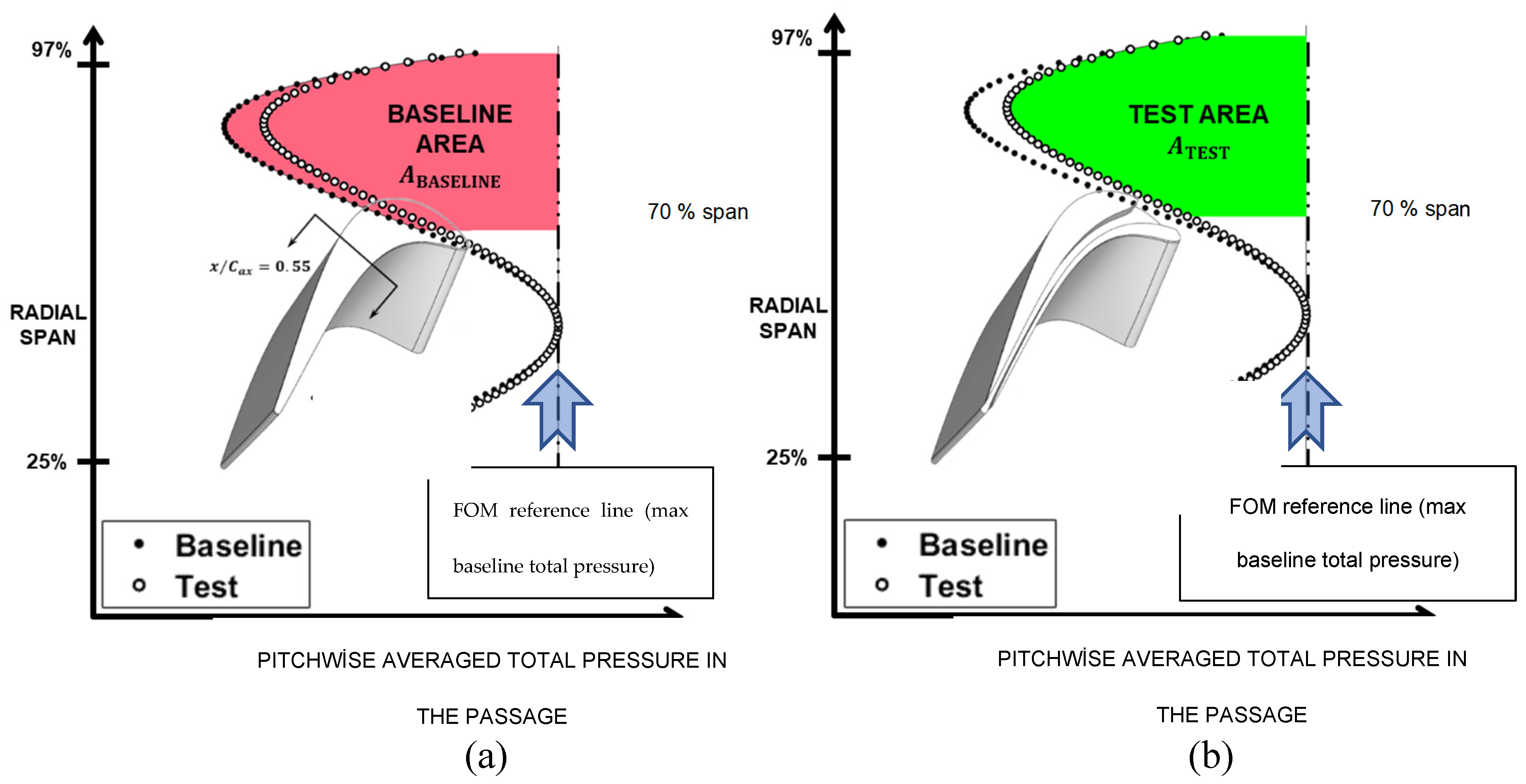
The weakened tip vortex structure of the new design also reduces the level of strong interactions with the counter-rotating upper passage vortex, causing distinct total pressure field variations in the last 30 percent of the blade height. These areas are typically calculated using a numerical integration technique between 70 % and 97 % span.
The FOMTip as a useful performance parameter of the new tip leakage mitigator is defined as follows:
Baseline Flat Tip Computations
Predictions from an AFTRF turbine blade with a flat tip gap of 0.80% are used as a baseline in all predictions. This tip clearance value remains unchanged for all new design cases with a tip leakage mitigator. Three baseline metrics of comparison are generated from these computations: the baseline passage averaged total pressure based figure of merit FOMTip at the rotor exit, the baseline total-to-total stage isentropic efficiency, and the baseline rate of leakage mass flow through the clearance gap. The values of these three parameters provide the benchmark against which alternative designs are compared. The computations for the baseline Flat Tip (FT) predict a tip-gap mass flow rate of 8.38 g/s and a total-to-total isentropic efficiency of 89.44%. Streamlines in the tip region of the blade on a vertical plane section positioned at x/Cax = 0.3, are presented in Figure 24.a. This plane vertical to the flat tip is also normal to the camberline of the tip airfoil. The spanwise distribution circumferentially averaged total pressure data for a single passage is presented in Figure 24.b. The total pressure deficit due to the presence of the tip leakage vortex is seen between the 70% to 95% spans. This spanwise interval also carries the upper passage vortex related aerodynamic losses. The circumferentially-averaged reference data set in Figure 24 serves as the reference level for each new tip mitigator design. The total-pressure-based tip figure of merit, FOMTip, is generated based on the difference between the passage averaged data of the baseline and that of the test cases as defined in Equation 8 and Figure 23.
Results and Discussion of Coandă Ejector-Based Designs
Design geometries: The streamlines in the tip region of the blade on a plane section positioned at x/Cax = 0.3, oriented normal to the blade camber generated from the computations of all ejector-based concepts are presented in Figure 25,
Figure 26, Figure 27, Figure 28, Figure 29, Figure 30, Figure 31, Figure 32, Figure 33, Figure 34, Figure 35 and Figure 36.
In Figure 25, the impact of the implementation of the first ejector channel on the flat baseline tip in AFTRF is shown. The flow in the tip gap over the ejector channel is predicted to sustain a reduction in relative velocity and become entrained in the channel.
In Figure 26, the impact of implementing the Coandă-surface in concept EC on the flow field in the ejector channel is seen when compared to concept EB in Figure 25. The streamlines indicate that the flow is conforms to the highly convex contour of the Coandă-surface. The suction effect impacts the tip leakage flow as the recirculatory region in the ejector channel is seen to compress in the radial direction.
In Figure 27, the impact of the implementation of the linear incline in concept ECI on the near-SS wall of the ejector on the flow field is seen. The streamlines indicate that the impinging flow is being reflected into the ejector channel, facilitating the retention of tip leakage flow in the channel.
In Figure 28, the impact of the increased cavity depth in concept ECI5 on the flow field is seen. The recession of the recirculatory flow within the cavity enhances the space for the diversion of the leakage fluid in the ejector channel.
In Figure 29, the impact of the PS notch in concept ECI5n on the flow field is seen. The notch effectively conditions the incoming leakage flow and is predicted to enforce fluid in the ejector channel more directly.
In Figure 30, the impact of the hybrid squealer in concept ECI5n-HS on the flow field is seen. The strong recirculatory action seen in the hybrid squealer cavity creates additional blockage effect in the tip gap further reducing the net mass flow of the leakage fluid from the SS corner. The hybrid squealer is just a cavity with connection to the wake flow through the trailing edge.
Figure 31 shows the impact of the hybrid ejection squealer in concept ECI5n-HES on the reduction of leakage flow. The TE end of the hybrid squealer cavity in ECI5n-HS is opened to a thin passage that connects the cavity of the hybrid squealer to the main ejector channel. The thin passage connecting the hybrid squealer and the main ejector channel is presented in Figure 16. The leakage fluid attracted the ejector channel and the hybrid squealer is ejected into the already lossy wake region of the blade.
Figure 32 presents 'a linear inclination' on the SS wall of the hybrid ejection squealer cavity as ECI5n-OHES. The streamlines indicate a more effective tip leakage mitigation because of the addition of this inclined surface on the inner part of the suction side rim. A comparison in Table 2 indicates that ECI5n-HS and ECI5n-OHES are the two most effective tip mitigator designs out of the 11 new designs, as far as the leakage mass flow rate reduction, total-to-total isentropic efficiency improvement, and FOMTip gain. It should be noted that the overall volume of the hybrid cavity ECI5n-OHES is relatively smaller than ECI5n-HS and ECI5n-HES.
Figure 33, the impact of the second ejector channel in concept D-ECI5n on the flow field is seen when compared to concept ECI5n-OHES in Figure 32. A second Coandă surface is added to the hybrid squealer channel which is also connected to the main ejector channel.
In D-ECI5n-HS, the unutilized surface next to the second ejector channel in the previous design D-ECI5n is used to implement an even smaller hybrid squealer, Figure 34. The rim thickness of this hybrid squealer is 2 mm. The recirculatory action seen in the hybrid squealer cavity creates a reasonable blocking effect in the tip gap that reduces the mass flow of the overall leakage fluid.
T-ECI5n includes the addition of a third Coandă surface to the smaller hybrid squealer near the SS rim resulted in the design presented in Figure 35. The streamlines indicate that the leakage flow is conforming to the contour of the third Coandă-surface, increasing the rate of tip leakage fluid entering into the third ejector channel when compared to design D-ECI5n-HS without the third Coandă surface.
In Figure 36, concept EB5 is appended to the design matrix to coincide with the experimental design matrix presented in later sections; in the experimental phase, all designs are tested using a fixed cavity depth of 5 mm. Therefore, the baseline ejector channel computation was conducted with a cavity depth of 5 mm, denoted concept EB5, to provide a proper match between computational and experimental geometries.
Spanwise distribution of stage exit total pressure leading to FOMtip: The change of total pressure and temperature from the stage inlet value controls the local total-to-total turbine efficiency. One of the goals of the current study is to capture the relative improvements or detriments whenever a new tip leakage mitigation concept is under investigation. The circumferentially averaged total pressure for the four design cases which had an efficiency gain of more than 0.25 % as a passage average in the tip vortex/passage vortex-dominated area is presented in Figure 37. The spanwise distribution of absolute total pressure between 70% span and 100% span is shown in the figure. The highest efficiency gain of 0.49% comes from ECI5n-OHES (Ejector Coandă-I5n Optimized Hybrid Ejection Squealer) as shown in Figure 34. A slightly lower gain of 0.43% is apparent in the design ECI5n-HS, presented in Figure 30. In the circumferentially averaged total pressure plots, the green areas represent spanwise locations where there is a total pressure improvement compared to the baseline FT, and the red areas denote spanwise locations where there is a total pressure detriment. The difference in circumferentially averaged total pressure data is used to generate an FOMTip for each concept using equation 8. The method of calculation is also graphically explained in Figure 23. The design computations in Figure 37 show that the effective tip leakage mitigators reduce the leakage mass flow rate and the strength of the tip vortex forming in the passage. The reduction in the vortex strength results in a much weaker interaction of the tip leakage vortex with the upper passage vortex originating from the rotor passage as shown in the green areas of the four selected pressure distributions of the new designs in Figure 37. The efficiency gains obtained from the ejector-Coandă concept ECI5 in Figure 37 (a) can almost be doubled by adding a PS notch and a hybrid squealer of ECI5n-OHES as presented in Figure 37 (d). Connecting the hybrid squealer to the wake region of the blade by a channel in case ECI5n-HES has a very slight efficiency gain of 0.03 % against the design ECI5n-HS.
Comparison of 11 Tip Leakage Mitigator Design Cases
A comparison of all cases evaluated computationally is given in Table 3. The five best cases providing a total-to-total isentropic efficiency gain of more than 0.25% are (ECI5, Figure 28), (ECI5n, Figure 29), (ECI5n-HS, Figure 30), (ECI5n-HES, Figure 31) and (ECI5n-OHES, Figure 32). A combination of the ejector having a Coandă surface near the PS rim and a hybrid ejection squealer provided non-negligible efficiency gains in the range between 0.27% and 0.49 %. The current computations show that adding a secong or third ejector channel on the tip platform does not significantly change the total to total efficiency gain when compared to the previously discussed. Figure 38 compares the percent change in , and FOMTip for all 11 designs compared to AFTRF baseline flat tip. Arrowed des,gns show the best five design cases obtained.
A slightly deeper baseline ejector case EB5 with a channel depth of 5 mm was also evaluated to help the experimental effort described in the preceding paragraphs. EB5 as shown in Figure 36, resulted in a slightly less efficient design when compared to EB
The correlation between FOMTip and : The exchange rate between and FOMTip for all eleven designs compared to the baseline Flat Tip (FT) is presented in Figure 39. A linear correlation of all 11 points results in about a 0.5 % gain in for an 11.2% increase in FOMTip. This strong correlation between and FOMTip indicates that the use of a figure of merit based on stage exit total pressure is extremely useful and time saving in assessing new tip designs in turbine research facilities. The results in Table 3 and Figure 39 clearly show that FOMTip alone is sufficient to understand the impact of the new tip leakage mitigation scheme on the stage total-to-total efficiency. Although the RANS based computation of is straight forward, the experimental evaluation of in the AFTRF is extremely cumbersome with high level of experimental uncertainty. This uncertainty is mainly because of the much lower level of pressure and temperature drop in large-scale and low-speed turbine research facilities. This observed correlation strongly supports the idea of using FOMTip based on stage exit total pressure surveys, instead of turbine efficiency in the experimental/computational studies in the AFTRF and all other large-scale, low-speed rotating turbine rigs.
Conclusions
This paper presents a conceptual development of novel ejector-based, Coandă-surface assisted tip leakage mitigation schemes. The predicted performance improvements of the new tip designs are presented after explaining the aerodynamic concept development for the novel tip geometries.
The designs are based on direct geometric modifications to the turbine blade tip, effectively promoting an effective redirection of tip leakage fluid via specific channels. The proposed ejector channels operate in conjunction with strategic Coandă surfaces to alter the path of the leakage fluid, promoting an effective leakage fluid delivery into the blade's wake.
Multiple schemes are assessed, including single-ejector, single-ejector with “hybrid” squealer, double-channeled, and triple-channeled designs. A pressure side corner notch and hybrid squealer channel designs are also evaluated. Extensive experimental validation of the baseline flow computations for the large-scale HP stage in the AFTRF is also presented.
This paper computationally investigated eleven novel tip leakage mitigation concepts and compared their aerodynamic performance to a baseline Flat Tip (FT). The computational studies performed in the AFTRF environment indicated that ejector-based concepts EB, EC, ECI, and ECI5, and ECI5n progressively reduced the tip leakage mass flow rate, beginning at a reduction of 5.01% for concept EB, and ending with a 9.91% mass flow reduction for concept ECI5n. This result indicated that the implementation of the baseline ejector EB, is effective at reducing tip gap mass flow rate, and design modifications using Coandă-surfaces and inclinations such as the ones from concept EC to concept ECI5n, can further improve the tip leakage flow blocking tendency.
The range of total-to-total isentropic efficiency improvement also increases significantly compared to the baseline Flat Tip (FT), starting with a of 0.25% for concept EB, and increasing quantifiably through the ejector design evolution to 0.30% for concept ECI5n.
Mass flow reduction compared to the baseline Flat Tip (FT) for hybrid squealer concepts ECI5n-HS, ECI5n-HES, and ECI5n-OHES are predicted to be 12.29%, 14.32%, and 14.80%, respectively. For these concepts, improvements in total-to-total isentropic efficiency compared to the baseline Flat Tip (FT) were predicted to be 0.43%, 0.46%, and 0.49% with total pressure-based rotor-exit FOMTip magnitudes following a similar trend.
The five best cases providing a total-to-total isentropic efficiency gain of more than 0.25% are (ECI5, Figure 28), (ECI5n, Figure 29), (ECI5n-HS, Figure 30), (ECI5n-HES, Figure 31) and (ECI5n-OHES, Figure 32).
Multiple ejector concepts D-ECI5n, D-ECI5n-HS, and T-ECI5n, are predicted to offer similar
performance levels when compared to the five best cases reported in the preceding paragraph. Adding hybrid squealer cavities near the pressure side does not significantly improve the leakage flow mitigation characteristic of the five best cases.
There is a strong correlation between and FOMTip for all eleven designs compared to the baseline Flat Tip (FT). A linear correlation of all 11 points results in about a 0.5 % gain in for an 11.2% increase in FOMTip. This strong correlation indicates that the use of a figure of merit based on stage exit total pressure is extremely useful and time-saving in assessing new tip designs in turbine research facilities and in computational efforts. Current results show that FOMTip alone is effective to predict the impact of the new tip leakage mitigation scheme on the stage total-to-total efficiency.
Although the RANS-based computation of is straightforward, the experimental evaluation of in the AFTRF is extremely cumbersome with high level of experimental uncertainty. This uncertainty is mainly because of the much lower level of stage pressure drop and temperature drop in large-scale and low-speed turbine research facilities.
The implementation of the tip leakage mitigation concepts presented in this study in a high-speed turbine cascade environment with transonic stage exit conditions and their tip heat transfer impact is currently in the publication phase.
Acknowledgments
We want to express our sincere gratitude to Drs. A. Sadagopan, V.C. Andichamy, J.Town and M.Doshi for their involvement in certain phases of this research. Mr.M.Catalano and K.Hellers' support for the high-performance computing infrastructure was invaluable. The authors are indebted to the Department of Aerospace Engineering at Penn State.
Nomenclature
| Baseline area for FOM calculation | |
| Test area for FOM calculation | |
| Area of turbine blade tip | |
| AFTRF | Axial Flow Turbine Research Facility |
| Blade axial chord | |
| D-ECI5n | Dual Ejector Coandă-I5n |
| D-ECI5n-HS | Dual Ejector Coandă-I5n Hybrid Squealer |
| DTP | Dynamic total pressure |
| E3 | Energy Efficient Engine |
| EB | Ejector Baseline |
| EB5 | Ejector Baseline-5 |
| EC | Ejector Coandă |
| ECI | Ejector Coandă-I |
| ECI5 | Ejector Coandă-I5 |
| ECIn | Ejector Coandă-In |
| ECI5n | Ejector Coandă-I5n |
| ECIn-HS | Ejector Coandă-In Hybrid Squealer |
| ECI5n-HS | Ejector Coandă-I5n Hybrid Squealer |
| ECI5n-HES | Ejector Coandă-I5n Hybrid Ejection Squealer |
| ECI5n-OHES | Ejector Coandă-I5n Optimized Hybrid Ejection Squealer |
| FT | Flat Tip |
| FOMTip | Total pressure-based tip figure of merit |
| h | blade height |
| HP | High pressure |
| LE | Leading edge |
| Tip gap mass flow rate | |
| Reference tip gap mass flow rate | |
| N | Turbine rotational speed |
| NGV | Nozzle guide vane |
| Total Pressure | |
| Ambient pressure | |
| PS | Pressure side |
| RPM | Revolutions per minute |
| r | Radial component |
| SS | Suction side |
| SLA | Stereolithography |
| SQT | Squealer Tip |
| TKE | Turbulent Kinetic Energy |
| t | Effective tip clearance |
| Total temperature | |
| TE | Trailing edge |
| T-ECI5n | Triple Ejector Coandă-I5n |
| Velocity vector | |
| x | Axial component |
|
SUBSCRIPTS 1, 2, 3 |
Stage inlet, intra-space, rotor exit |
| GREEK | |
| Specific heat capacity ratio | |
| Total-to-total isentropic efficiency | |
| Density | |
| θ | Tangential direction |
| Angular velocity |
References
- R. S. Bunker, “Axial Turbine Blade Tips: Function, Design, and Durability,” AIAA Journal of Propulsion and Power, vol. 22, no. 2, pp. 271–285, Mar. 2006. [CrossRef]
- J. D. Denton, “The 1993 IGTI Scholar Lecture: Loss Mechanisms in Turbomachines,” ASME Journal of Turbomachinery, vol. 115, no. 4, pp. 621–656, Oct. 1993. [CrossRef]
- J.-C. Han, S. Dutta, and S. Ekkad, Gas Turbine Heat Transfer and Cooling Technology, 2nd edition. Boca Raton, FL: CRC Press, 2012.
- B. Sunden and G. Xie, “Gas Turbine Blade Tip Heat Transfer and Cooling: A Literature Survey,” Heat Transfer Engineering, Jun. 2010. [CrossRef]
- Y. W. Kim and D. E. Metzger, “Heat Transfer and Effectiveness on Film Cooled Turbine Blade Tip Models,” ASME Journal of Turbomachinery, vol. 117, no. 1, pp. 12–21, Jan. 1995. [CrossRef]
- L. M. da Silva and J. T. Tomita, “A Study of the Heat Transfer in Winglet and Squealer Rotor Tip Configurations for a Non-Cooled HPT Blade Based on CFD Calculations,” presented at the ASME Turbo Expo 2013: Turbine Technical Conference and Exposition. [CrossRef]
- P. Vass and T. Arts, “Numerical Investigation of High-pressure Turbine Blade Tip Flows: Analysis of Aerodynamics,” Proceedings of the Institution of Mechanical Engineers, Part A: Journal of Power and Energy, Sep. 2011. [CrossRef]
- A. Ameri, E. Steinthorsson, and D. L. Rigby, “Effect of Squealer Tip on Rotor Heat Transfer and Efficiency,” Journal of Turbomachinery, vol. 120, no. 4, pp. 753–759, Oct. 1998. [CrossRef]
- Camci, D. Dey, and L. Kavurmacioglu, “Aerodynamics of Tip Leakage Flows Near Partial Squealer Rims in an Axial Flow Turbine Stage,” ASME Journal of Turbomachinery, vol. 127, no. 1, pp. 14–24, Feb. 2005. [CrossRef]
- G. S. Azad, J.-C. Han, R. S. Bunker, and C. P. Lee, “Effect of Squealer Geometry Arrangement on a Gas Turbine Blade Tip Heat Transfer,” Journal of Heat Transfer, vol. 124, no. 3, pp. 452–459, May 2002. [CrossRef]
- N. L. Key and T. Arts, “Comparison of Turbine Tip Leakage Flow for Flat Tip and Squealer Tip Geometries at High-Speed Conditions,” Journal of Turbomachinery, vol. 128, no. 2, pp. 213–220, Mar. 2004. [CrossRef]
- S. E. Lee, S. W. Lee, and H. S. Kwak, “Tip Leakage Aerodynamics Over Stepped Squealer Tips in a Turbine Cascade,” Experimental Thermal and Fluid Science, vol. 35, no. 1, pp. 135–145, Jan. 2011. [CrossRef]
- Dey, “Tip Desensitization in an Axial Flow Turbine,” Ph.D. Dissertation, The Pennsylvania State University, 2001.
- S. W. Lee and S. U. Kim, “Tip Gap Height Effects on the Aerodynamic Performance of a Cavity Squealer Tip in a Turbine Cascade in Comparison With Plane Tip Results: Part 1—Tip Gap Flow Structure,” Exp Fluids, vol. 49, no. 5, pp. 1039–1051, Nov. 2010. [CrossRef]
- Y. Liu, T.-L. Zhang, M. Zhang, and M.-C. Zhang, “Numerical and Experimental Investigation of Aerodynamic Performance for a Straight Turbine Cascade With a Novel Partial Shroud,” Journal of Fluids Engineering, vol. 138, no. 031206, Oct. 2015. [CrossRef]
- S. W. Lee, J. H. Cheon, and Q. Zhang, “The Effect of Full Coverage Winglets on Tip Leakage Aerodynamics Over the Plane Tip in a Turbine Cascade,” International Journal of Heat and Fluid Flow, vol. 45, pp. 23–32, Feb. 2014. [CrossRef]
- Zhou and F. Zhong, “A Novel Suction-Side Winglet Design Philosophy for High-Pressure Turbine Rotor Tips,” Journal of Turbomachinery, vol. 139, no. 111002, Jul. 2017. [CrossRef]
- K. Zhou and C. Zhou, “Aerodynamic Effects of an Incoming Vortex on Turbines With Different Tip Geometries,” Journal of Turbomachinery, vol. 143, no. 081009, Apr. 2021. [CrossRef]
- J. H. Cheon and S. W. Lee, “Tip Leakage Aerodynamics Over the Cavity Squealer Tip Equipped With Full Coverage Winglets in a Turbine Cascade,” International Journal of Heat and Fluid Flow, vol. 56, pp. 60–70, Dec. 2015. [CrossRef]
- J. S. Joo and S. W. Lee, “Heat/mass Transfer Over the Cavity Squealer Tip Equipped With a Full Coverage Winglet in a Turbine Cascade: Part 1 – Data on the Winglet Top Surface,” International Journal of Heat and Mass Transfer, vol. 108, pp. 1255–1263, May 2017. [CrossRef]
- S. W. Lee and J. S. Joo, “Heat/Mass Transfer Over the Cavity Squealer Tip Equipped With a Full Coverage Winglet in a Turbine Cascade: Part 2 – Data on the Cavity Floor,” International Journal of Heat and Mass Transfer, vol. 108, pp. 1264–1272, May 2017. [CrossRef]
- J. D. Coull, N. R. Atkins, and H. P. Hodson, “High Efficiency Cavity Winglets for High Pressure Turbines,” presented at the ASME Turbo Expo 2014: Turbine Technical Conference and Exposition. [CrossRef]
- Zhong and C. Zhou, “Effects of Tip Gap Size on the Aerodynamic Performance of a Cavity-Winglet Tip in a Turbine Cascade,” Journal of Turbomachinery, vol. 139, no. 101009, May 2017. [CrossRef]
- N. W. Harvey and K. Ramsden, “A Computational Study of a Novel Turbine Rotor Partial Shroud,” Journal of Turbomachinery, vol. 123, no. 3, pp. 534–543, Feb. 2000. [CrossRef]
- Y. Fu, F. Chen, H. Liu, and Y. Song, “Experimental and Numerical Study of Honeycomb Tip on Suppressing Tip Leakage Flow in Turbine Cascade,” Journal of Turbomachinery, vol. 140, no. 061006, Apr. 2018. [CrossRef]
- K. Du, Z. Li, J. Li, and B. Sunden, “Influences of a Multi-Cavity Tip on the Blade Tip and the Over Tip Casing Aerothermal Performance in a High Pressure Turbine Cascade,” Applied Thermal Engineering, vol. 147, pp. 347–360, Jan. 2019. [CrossRef]
- V. C. Andichamy, G. T. Khokhar, and C. Camci, “An Experimental Study of Using Vortex Generators As Tip Leakage Flow Interrupters in an Axial Flow Turbine Stage,” presented at the ASME Turbo Expo 2018: Turbomachinery Technical Conference and Exposition. [CrossRef]
- V. C. Andichamy, “An Investigation Using Tip Leakage Interrupter and Blade Slit to Mitigate Aerodynamic Losses in Axial Turbine Stage,” Ph.D. dissertation, The Pennsylvania State University.
- L. A. Kavurmacioglu, C. B. Senel, H. Maral, and C. Camci, “Casing Grooves to Improve Aerodynamic Performance of a Hp Turbine Blade,” Aerospace Science and Technology, vol. 76, pp. 194–203, May 2018. [CrossRef]
- Y. Zheng, X. Jin, H. Yang, Q. Gao, and K. Xu, “Effects of Circumferential Nonuniform Tip Clearance on Flow Field and Performance of a Transonic Turbine,”. [CrossRef]
- J. Gao, Q. Zheng, Y. Li, and G. Yue, “Effect of Axially Non-uniform Rotor Tip Clearance on Aerodynamic Performance of an Unshrouded Axial Turbine,” Proceedings of the Institution of Mechanical Engineers, Part A, vol. 226, no. 2, pp. 231–244, Mar. 2012. [CrossRef]
- S. Chen, Q. Meng, W. Li, Z. Zhou, and S. Wang, “Experimental Study on Axially Non-uniform Clearances in a Linear Turbine Cascade With a Cavity Squealer Tip,” Proceedings of the Institution of Mechanical Engineers, Part G, vol. 233, no. 5, pp. 1645–1655, Apr. 2019. [CrossRef]
- N. M. Rao and C. Camci, “Axial Turbine Tip Desensitization by Injection From a Tip Trench: Part 1 — Effect of Injection Mass Flow Rate,” presented at the ASME Turbo Expo 2004: Power for Land, Sea, and Air. [CrossRef]
- N. M. Rao and C. Camci, “Axial Turbine Tip Desensitization by Injection From a Tip Trench: Part 2 — Leakage Flow Sensitivity to Injection Location,” presented at the ASME Turbo Expo 2004: Power for Land, Sea, and Air. [CrossRef]
- Chen, W. Dawes, and H. Hodson, “Numerical and Experimental Investigation of Turbine Tip Gap Flow,” in 29th Joint Propulsion Conference and Exhibit, American Institute of Aeronautics and Astronautics. [CrossRef]
- R. J. Volino, “Control of Tip Leakage in a High-Pressure Turbine Cascade Using Tip Blowing,” Journal of Turbomachinery, vol. 139, no. 061008, Feb. 2017. [CrossRef]
- Z. Tao, W. Li, Z. Guo, Y. Chen, L. Song, and J. Li, “Aerothermal optimization of a turbine rotor tip configuration based on free-form deformation approach,” International Journal of Heat and Fluid Flow, vol. 110, p. 109644, Dec. 2024. [CrossRef]
- C. De Maesschalck, S. Lavagnoli, and G. Paniagua, “Blade Tip Carving Effects on the Aerothermal Performance of a Transonic Turbine,” Journal of Turbomachinery, vol. 137, no. 021005, Sep. 2014. [CrossRef]
- B. C. Cernat, M. Pátý, C. De Maesschalck, and S. Lavagnoli, “Experimental and Numerical Investigation of Optimized Blade Tip Shapes—Part I: Turbine Rainbow Rotor Testing and Numerical Methods,” Journal of Turbomachinery, vol. 141, no. 011006, Dec. 2018. [CrossRef]
- Maral, E. Alpman, L. Kavurmacıoğlu, and C. Camci, “A Genetic Algorithm Based Aerothermal Optimization of Tip Carving for an Axial Turbine Blade,” International Journal of Heat and Mass Transfer, vol. 143, p. 118419, Nov. 2019. [CrossRef]
- T.-J. Qin, Z.-X. Tong, D. Li, Y.-L. He, and T.-C. Hung, “Aerothermal Performance of Cavity Tip With Flow Structure Effects in a Transonic High-pressure Turbine Blade,” Energy, vol. 291, p. 130411, Mar. 2024. [CrossRef]
- B. D. Power, High Vacuum Pumping Equipment. London: Chapman & Hall, 1966.
- L. P. Timko, “Energy Efficient Engine High Pressure Turbine Component Test Performance Report,” NASA-CR-168289, Jan. 1984.
- C. Henri, “Device for Deflecting a Stream of Elastic Fluid Projected Into an Elastic Fluid,” US2052869A, Sep. 01, 1936.
- U. H. Von Glahn, “Use of the Coandă Effect for Jet Deflection and Vertical Lift with Multiple-flat-plate and Curved-plate Deflection Surfaces,” Sep. 1958.
- T. Khokhar, “An Aerothermal Study of Ejector-Based, Coandă-Surface-Driven, Gas Turbine Tip Leakage Mitigation Schemes: A Computational and Experimental Approach,” Ph.D. dissertation,The Pennsylvania State University, 2022.
- M. Doshi, “Computational Prediction of a Large-scale Hp Turbine Flow Against Measured Aerodynamic Data,” Master Thesis, The Pennsylvania State University, 2018.
- B. Lakshminarayana, C. Camci, I. Halliwell, and M. Zaccaria, “Design and Development of a Turbine Research Facility to Study Rotor-Stator Interaction Effects,” International Journal of Turbo and Jet Engines, vol. 13, no. 3, pp. 155–172, 1996.
- V. C. Andichamy, “An Investigation of Using Tip Leakage Interrupter and Blade Slit to Mitigate Aerodynamic Losses in Axial Turbine Stage,” Doctoral dissertation, The Pennsylvania State University, 2019.
- Ö. H. Turgut and C. Camci, “Factors Influencing Computational Predictability of Aerodynamic Losses in a Turbine Nozzle Guide Vane Flow,” Journal of Fluids Engineering, vol. 138, no. 051103, Jan. 2016. [CrossRef]
- M. A. Zaccaria, “An Experimental Investigation into the Steady and Unsteady Flow Field in an Axial Flow Turbine,” Ph.D. dissertation, The Pennsylvania State University, 1994.
- Town, “An Investigation of Rim Seal/Disk Cavity Flow and Its Interaction with High Pressure Turbine Rotor Flows,” Ph.D. dissertation, The Pennsylvania State University, 2015.
- R. Taylor, Propagation of Uncertainties. Sausalito, CA: University Science Books, 1997.
- M. Zaccaria and B. Lakshminarayana, “Investigation of Three-dimensional Flowfield at the Exit of a Turbine Nozzle,” AIAA Journal of Propulsion and Power, vol. 11, no. 1, pp. 55–63, Jan. 1995. [CrossRef]
Figure 1.
A fluid dynamic ejector as a device attracting the tip leakage fluid.
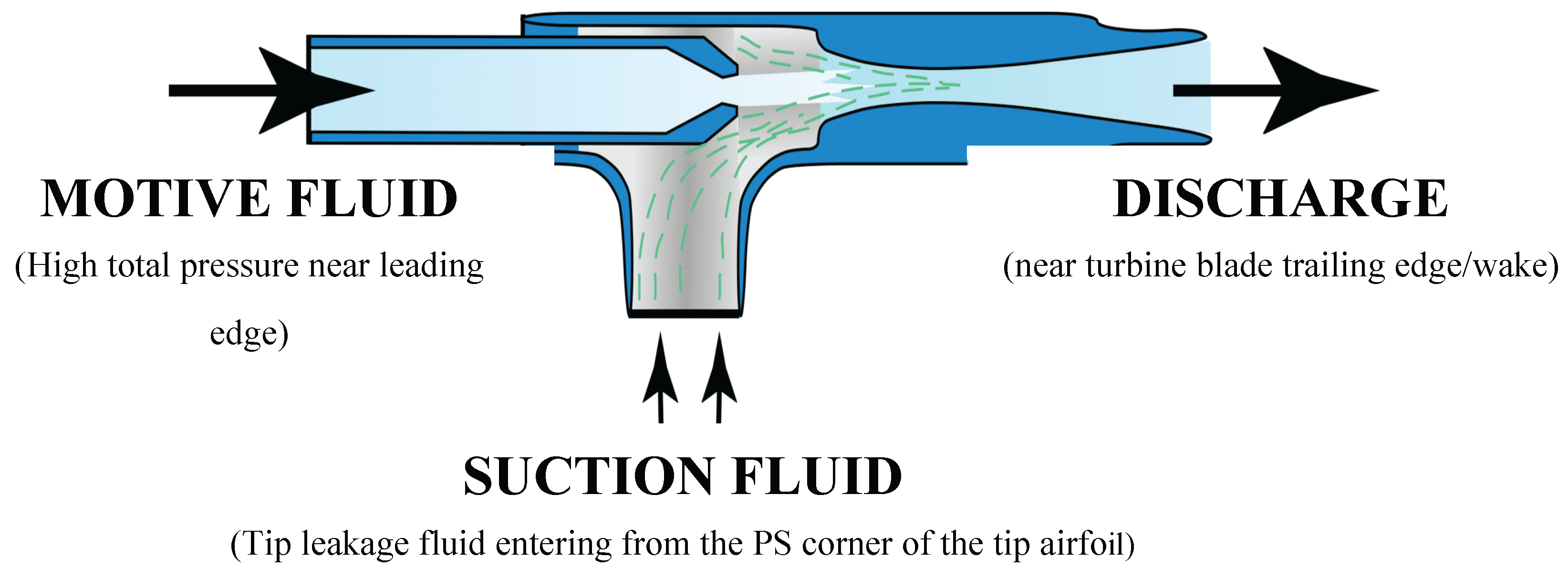
Figure 2.
(a). Untreated baseline AFTRF airfoil with flat tip. (b) Implementation of the fluid dynamic ejector on the tip platform for attracting the tip leakage fluid.
Figure 2.
(a). Untreated baseline AFTRF airfoil with flat tip. (b) Implementation of the fluid dynamic ejector on the tip platform for attracting the tip leakage fluid.
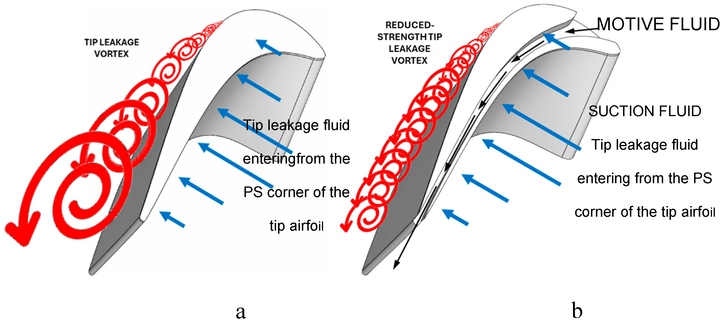
Figure 3.
AFTRF baseline Flat Tip (FT) geometry and cross-section at x/ Cax = 0.55.
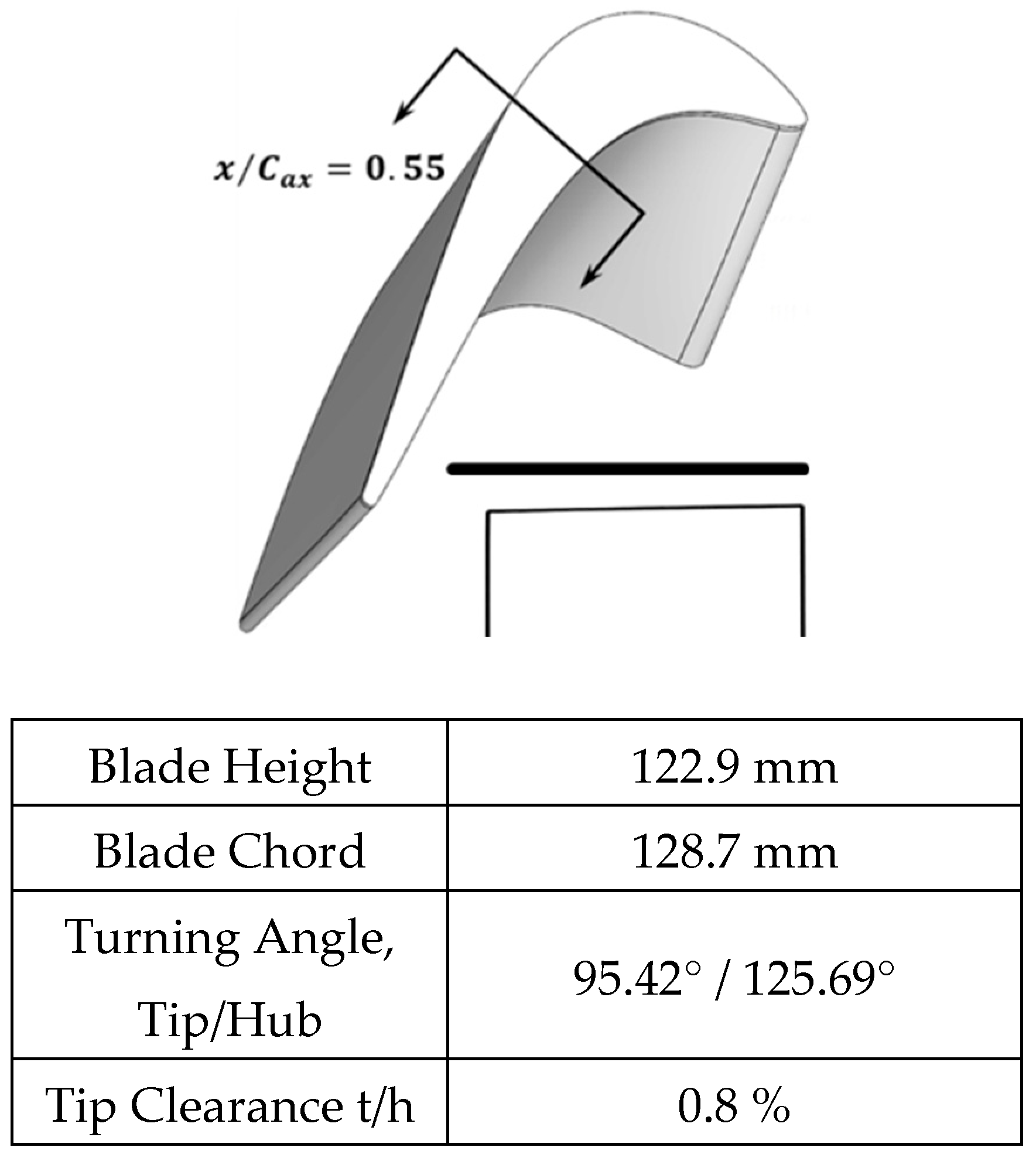
Figure 4.
Ejector Baseline (EB) and cross-section at x/ Cax = 0.55.
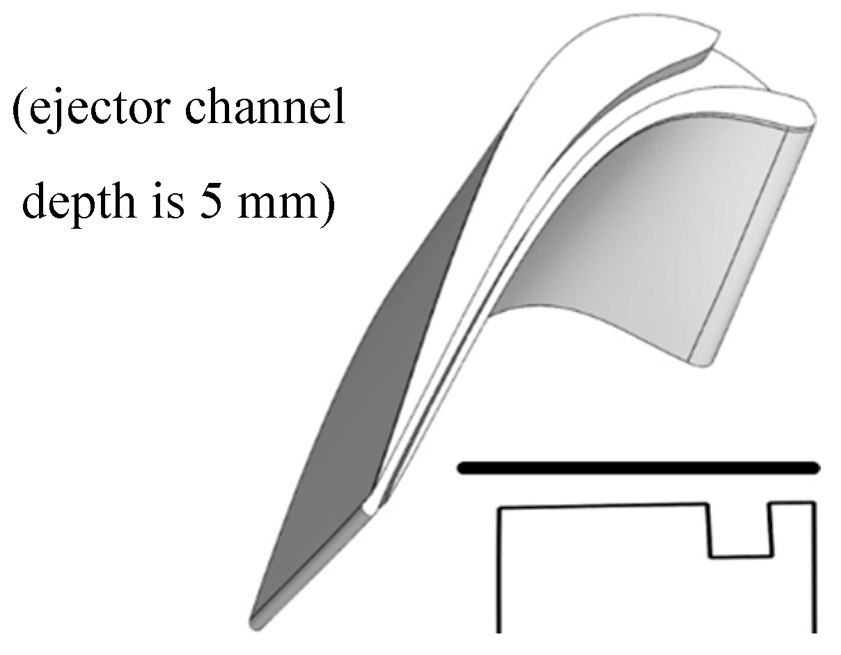
Figure 5.
Ejector Coandă (EC) and cross-section at x/ Cax = 0.55.
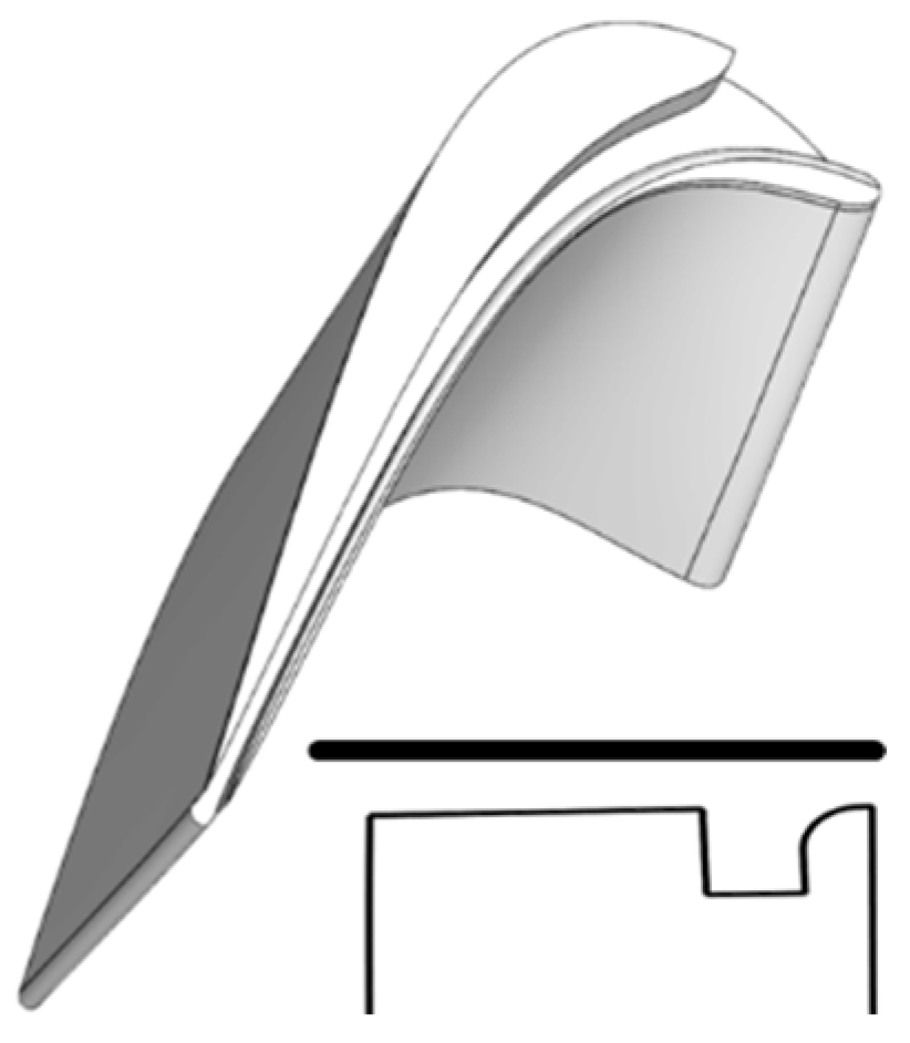
Figure 6.
Ejector Coandă-I (ECI) and cross-section at x/ Cax = 0.55.
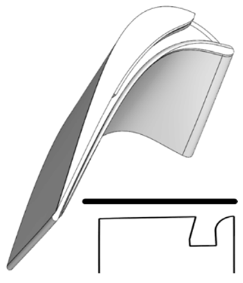
Figure 7.
Ejector Coandă-I5 (ECI5) and cross-section at x/ Cax = 0.55.
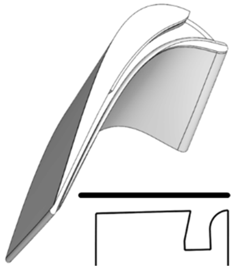
Figure 8.
Ejector Coandă-I5n (ECI5n) and cross-section at x/ Cax = 0.55.
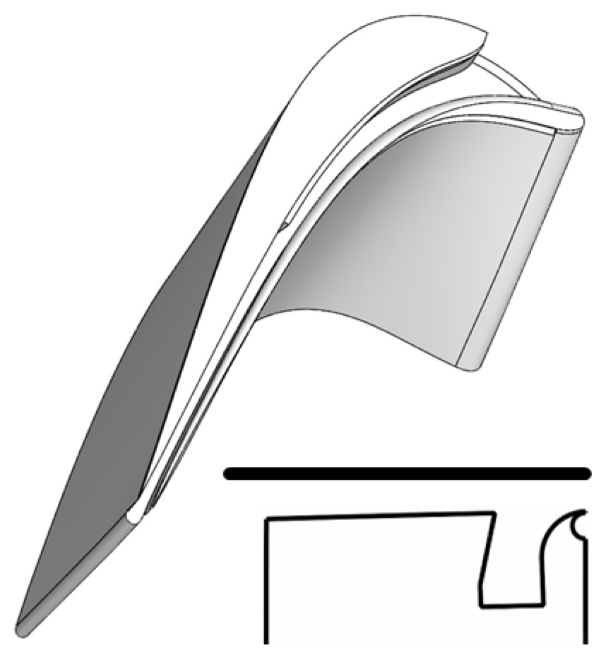
Figure 9.
Ejector Coandă-I5n Hybrid Squealer (ECI5n-HS) and cross-section at x/ Cax = 0.55.
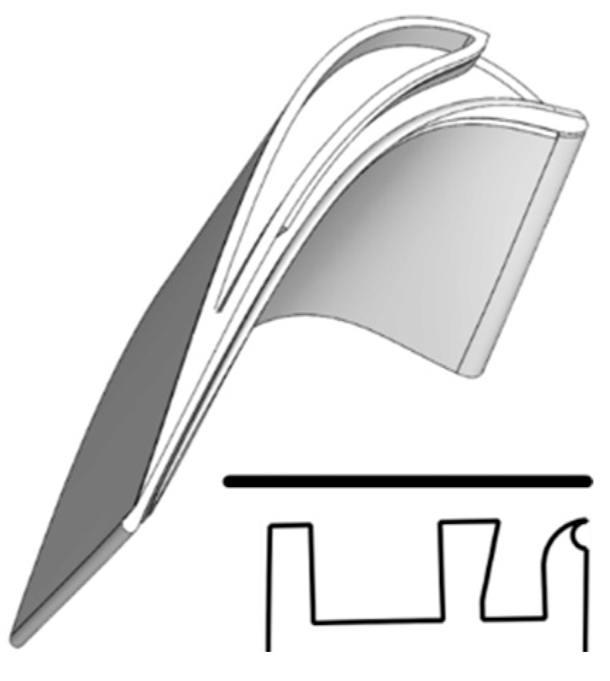
Figure 10.
Ejector Coandă-I5n Hybrid Ejection Squealer (ECI5n-HES) and cross-section at x/ Cax = 0.55.
Figure 10.
Ejector Coandă-I5n Hybrid Ejection Squealer (ECI5n-HES) and cross-section at x/ Cax = 0.55.
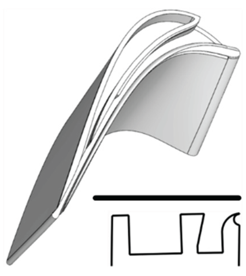
Figure 12.
Ejector Coandă-I5n Optimized Hybrid Ejection Squealer (ECI5n-OHES) and cross-section at x/ Cax = 0.55.
Figure 12.
Ejector Coandă-I5n Optimized Hybrid Ejection Squealer (ECI5n-OHES) and cross-section at x/ Cax = 0.55.
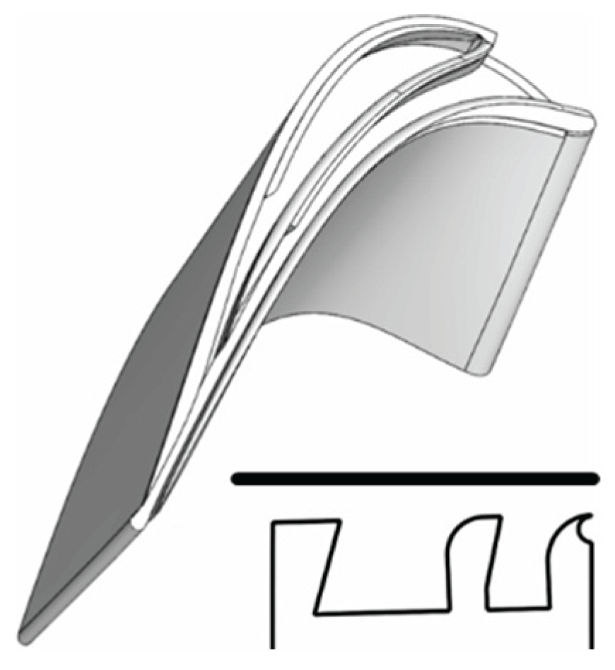
Figure 13.
Dual Ejector Coandă-I5n (D-ECI5n) and cross-section at x/ Cax = 0.55.
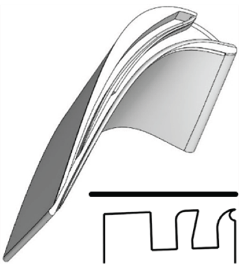
Figure 14.
Dual Ejector Coandă-I5n Hybrid Squealer (D-ECI5n-HS) and cross-section at x/ Cax = 0.55.
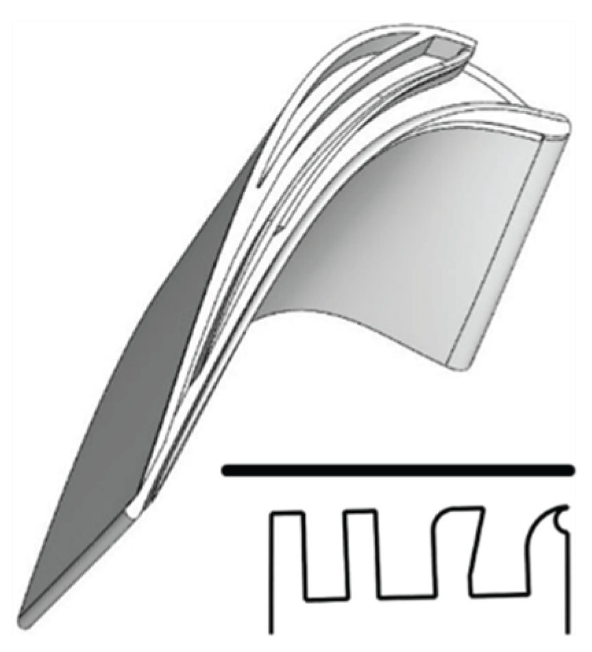
Figure 15.
Triple Ejector Coandă (T-ECI5n) and cross-section at x/ Cax = 0.55.
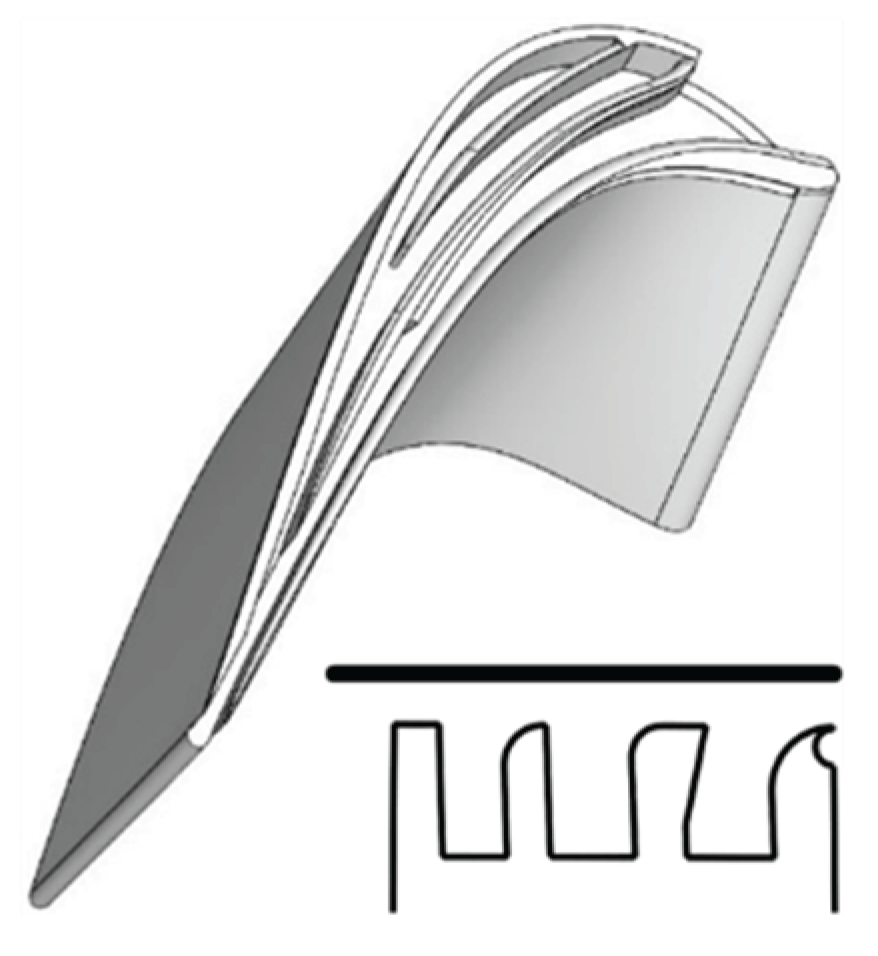
Figure 16.
Connected hybrid squealer and ejector channel near the TE ((ECI5n-HES).
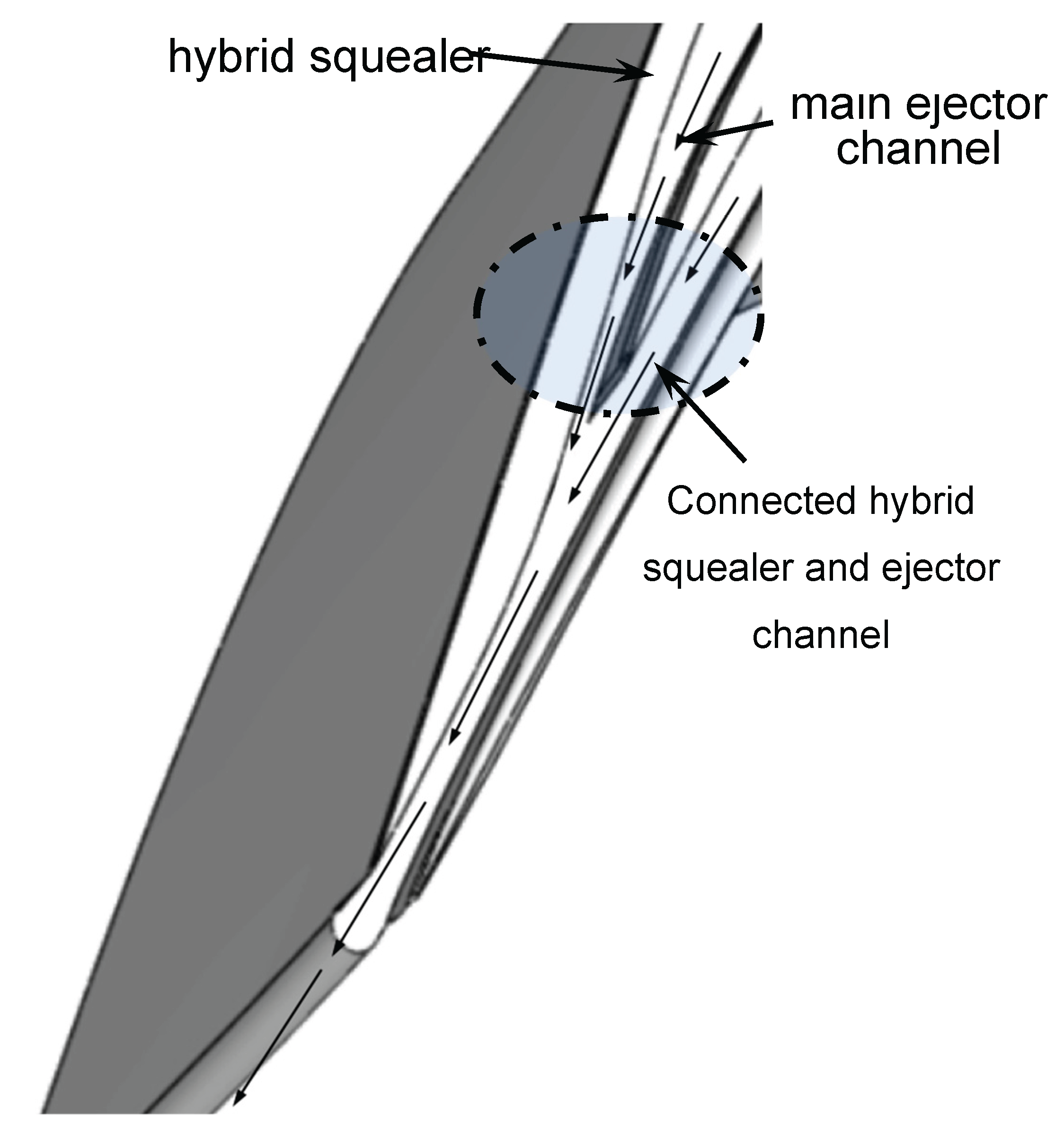
Figure 17.
Schematic of Penn State Axial Turbine Research Facility AFTRF.
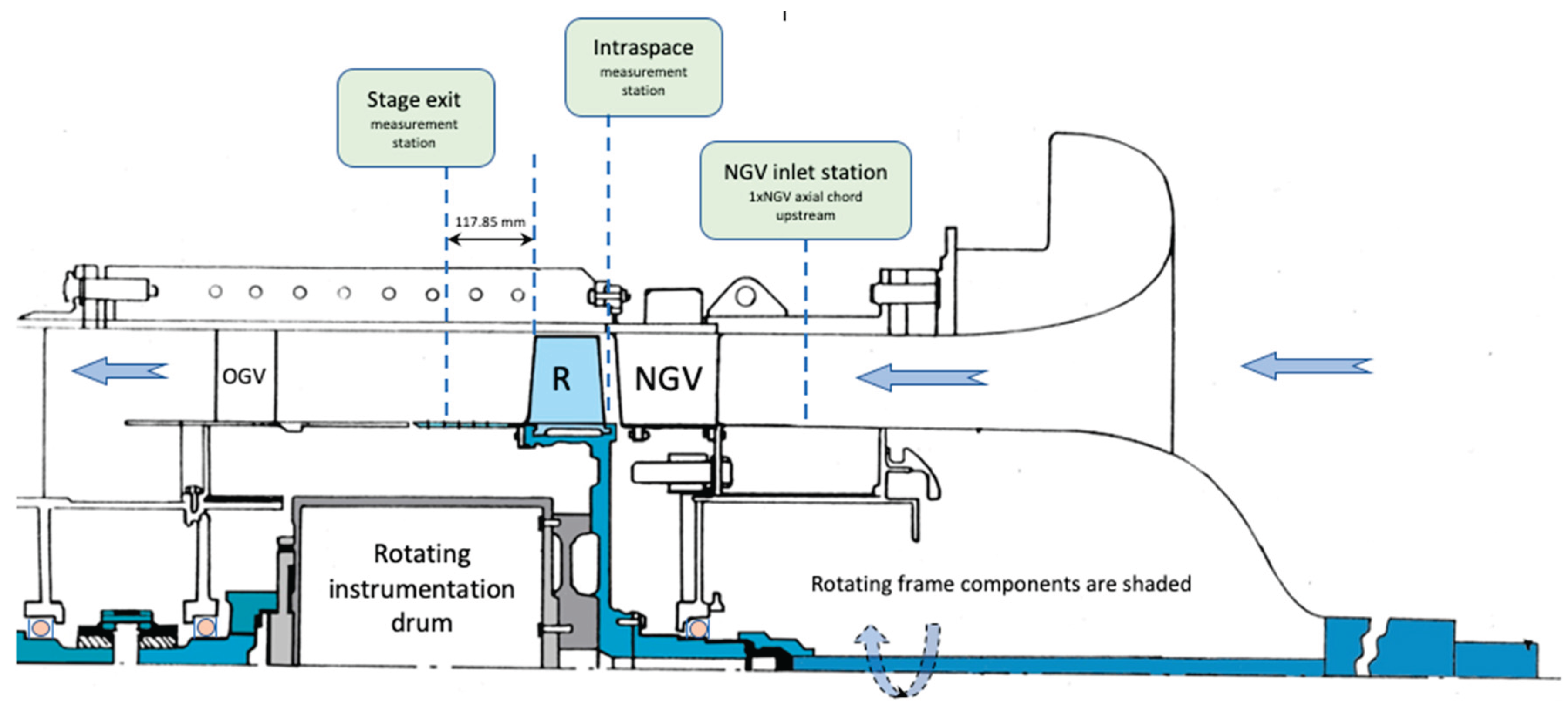
Figure 18.
(a) Measured Velocity and Turbulent kinetic energy profile of AFTRF at the NGV inlet, [50]. (b) Stage exit total pressure probe and its positioning at the rotor exit in the stationary frame of the AFTRF.
Figure 18.
(a) Measured Velocity and Turbulent kinetic energy profile of AFTRF at the NGV inlet, [50]. (b) Stage exit total pressure probe and its positioning at the rotor exit in the stationary frame of the AFTRF.
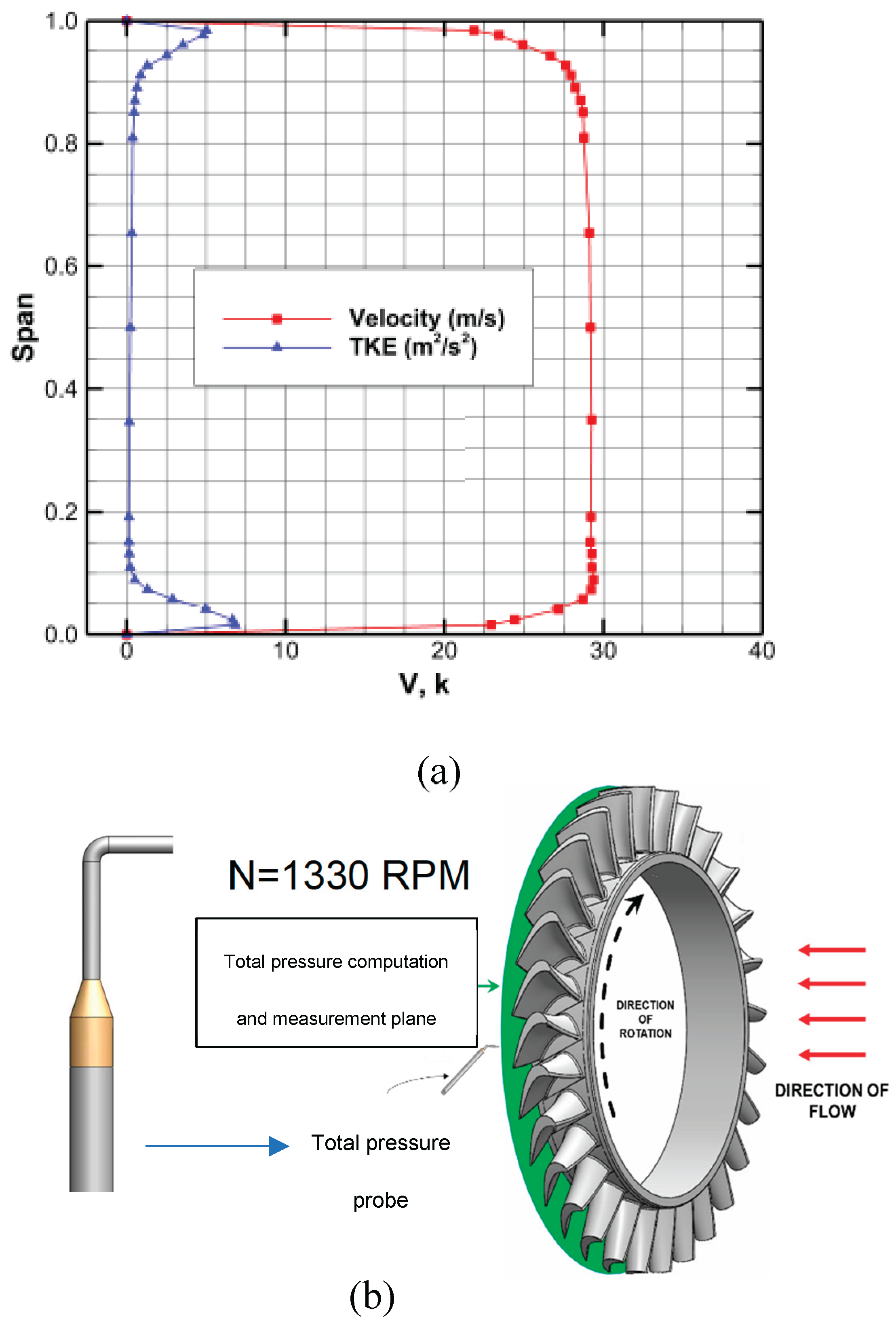
Figure 19.
AFTRF computational fluid domain.
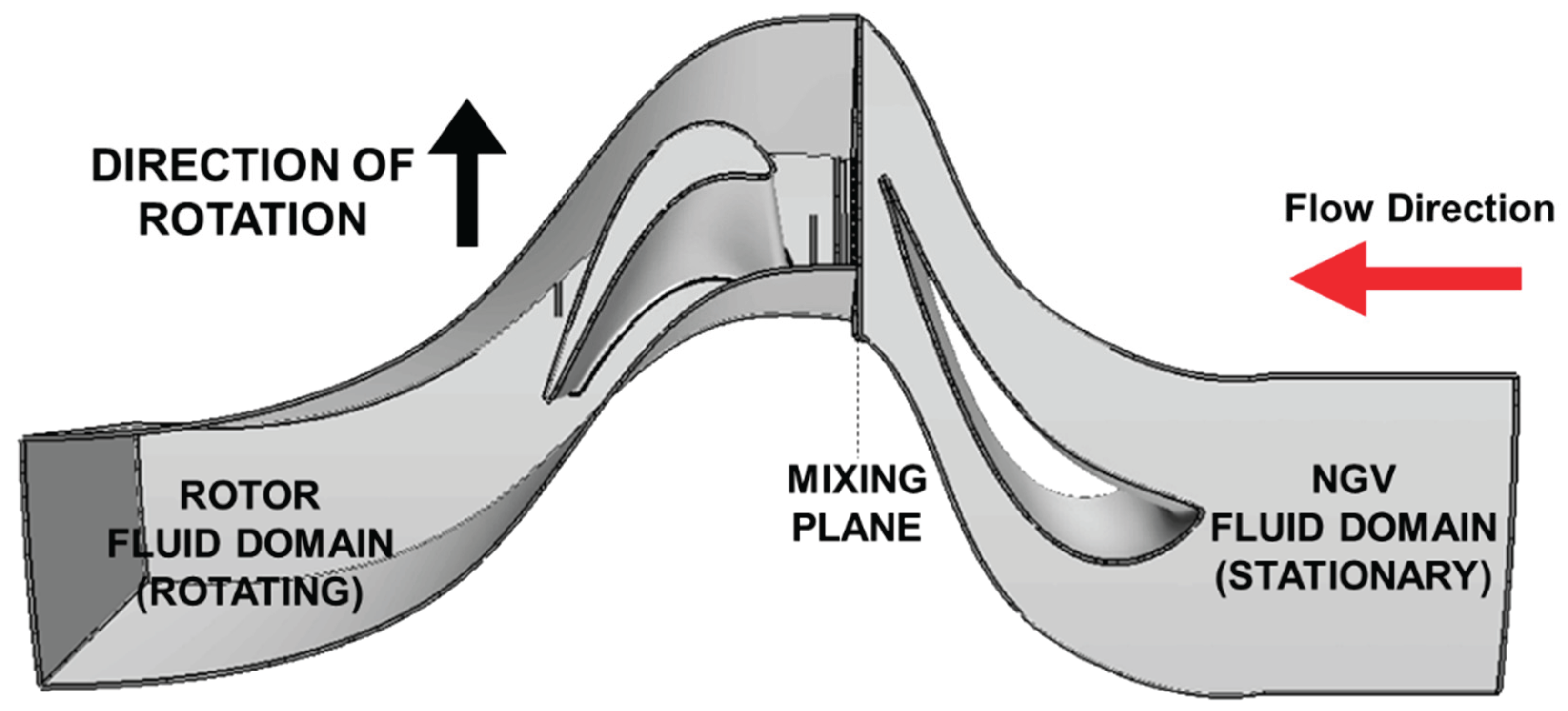
Figure 20.
The refined region near the rotor surface and NGV surface at the mid-span.
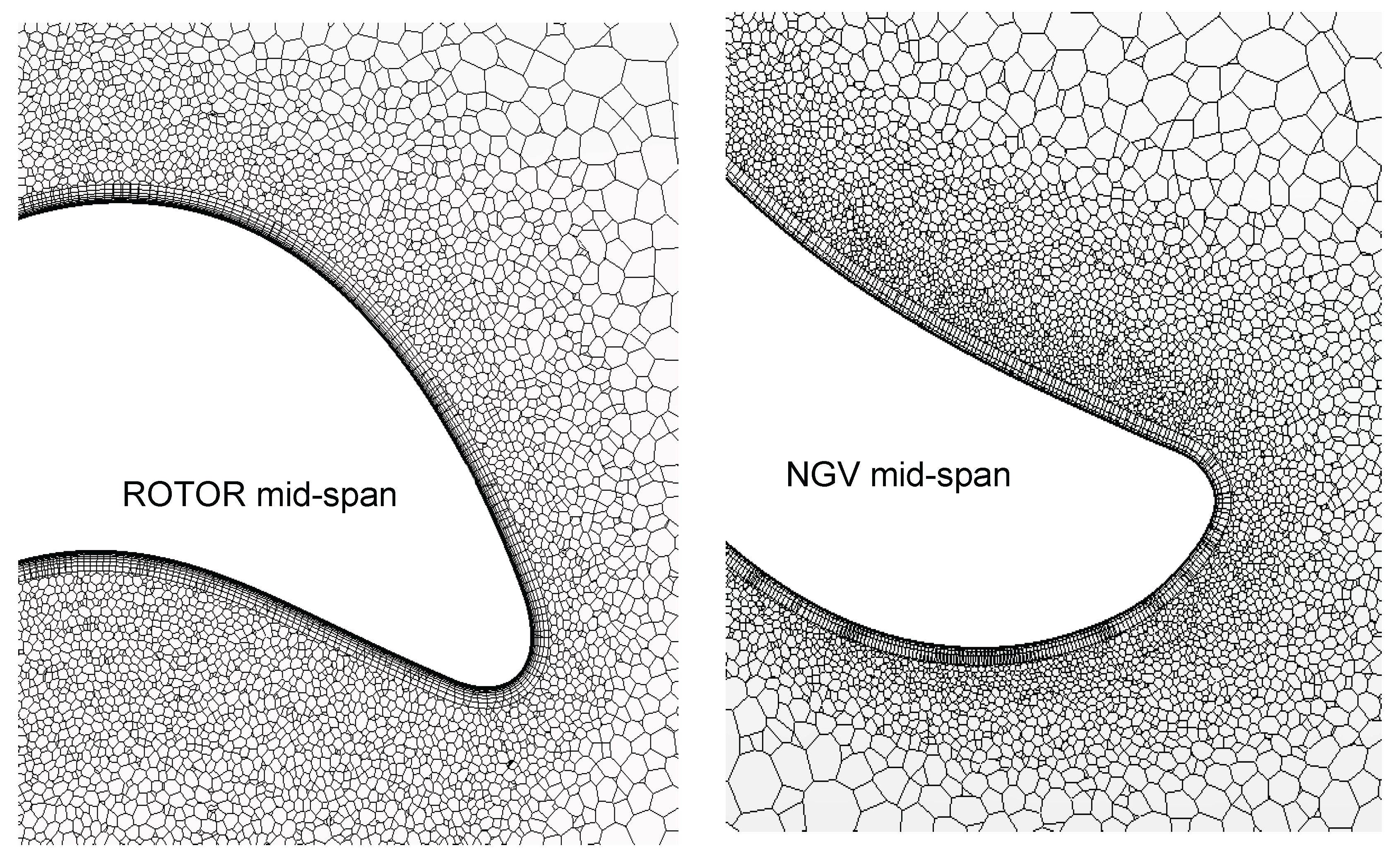
Figure 21.
Mesh on a cylindrical section at stage mid-span.
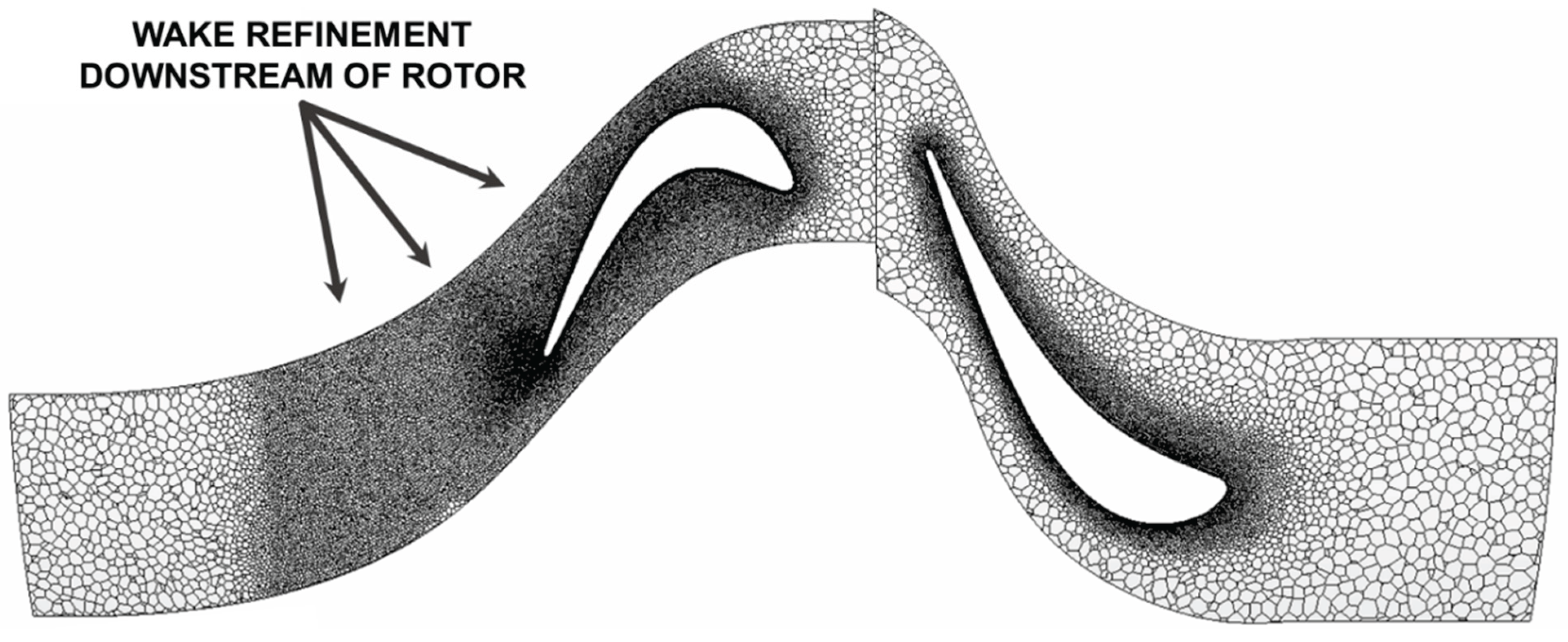
Figure 24.
(a) Baseline Flat Tip (FT), relative velocity streamlines in a plane positioned at x/Cax = 0.3, oriented normal to camber. (b) Baseline Flat Tip (FT), circumferentially averaged total pressure at rotor exit.
Figure 24.
(a) Baseline Flat Tip (FT), relative velocity streamlines in a plane positioned at x/Cax = 0.3, oriented normal to camber. (b) Baseline Flat Tip (FT), circumferentially averaged total pressure at rotor exit.
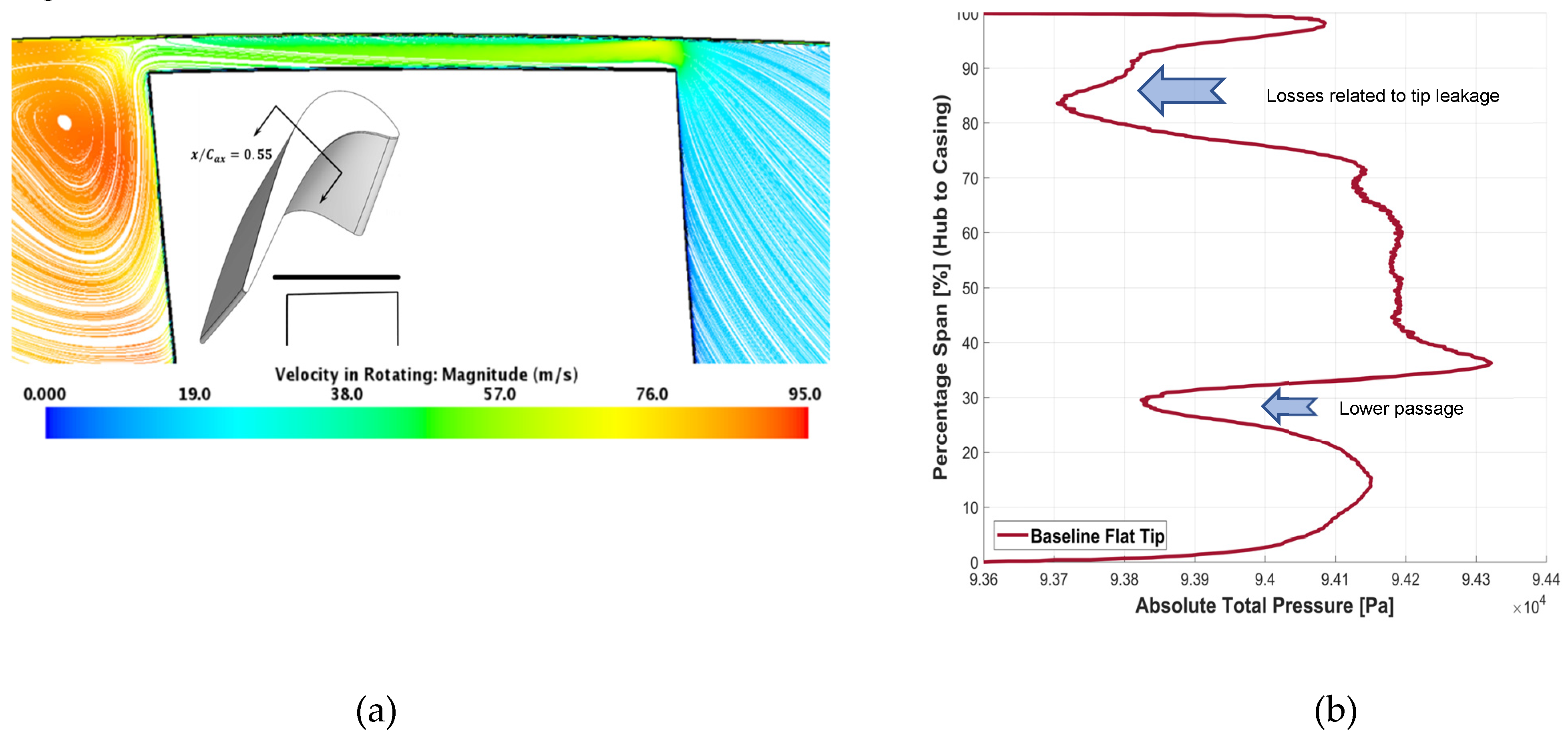
Figure 25.
EB relative streamlines at x/Cax = 0.3.
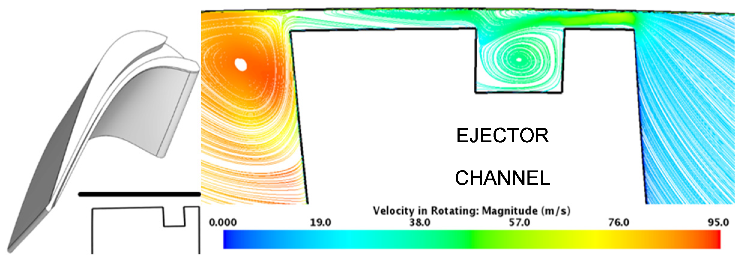
Figure 26.
EC relative streamlines at x/Cax = 0.3.
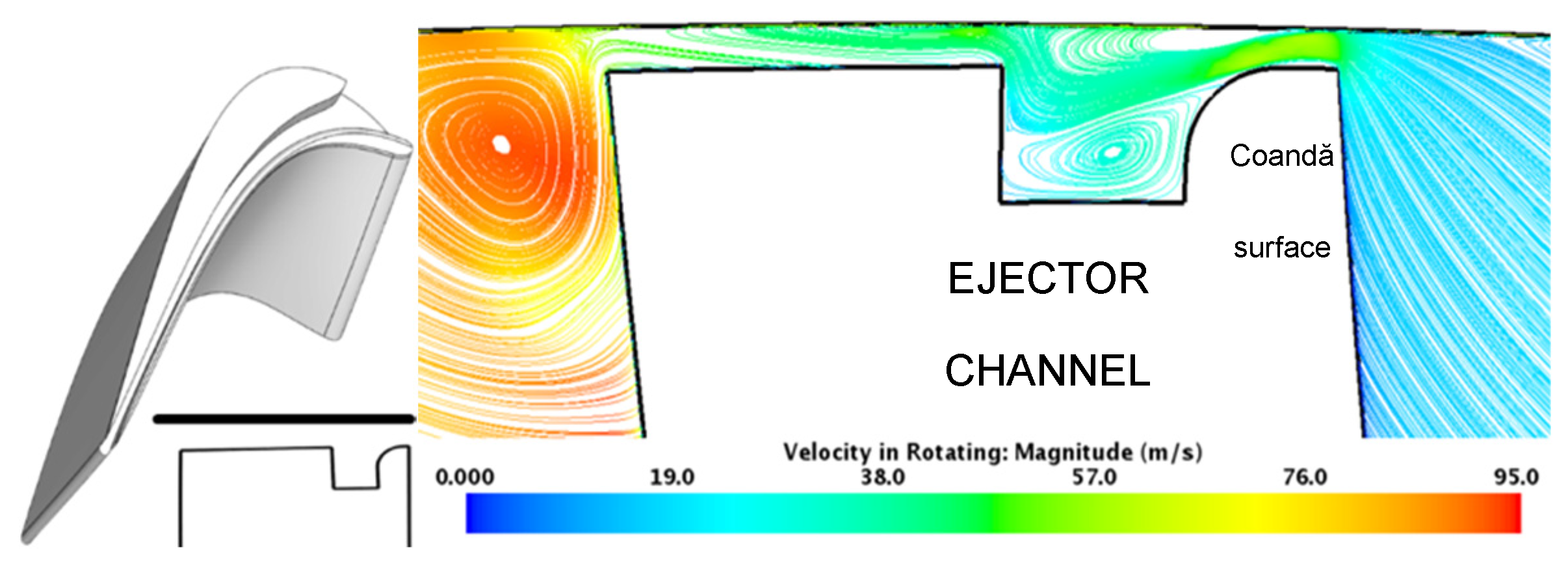
Figure 27.
ECI relative streamlines at x/Cax = 0.3.
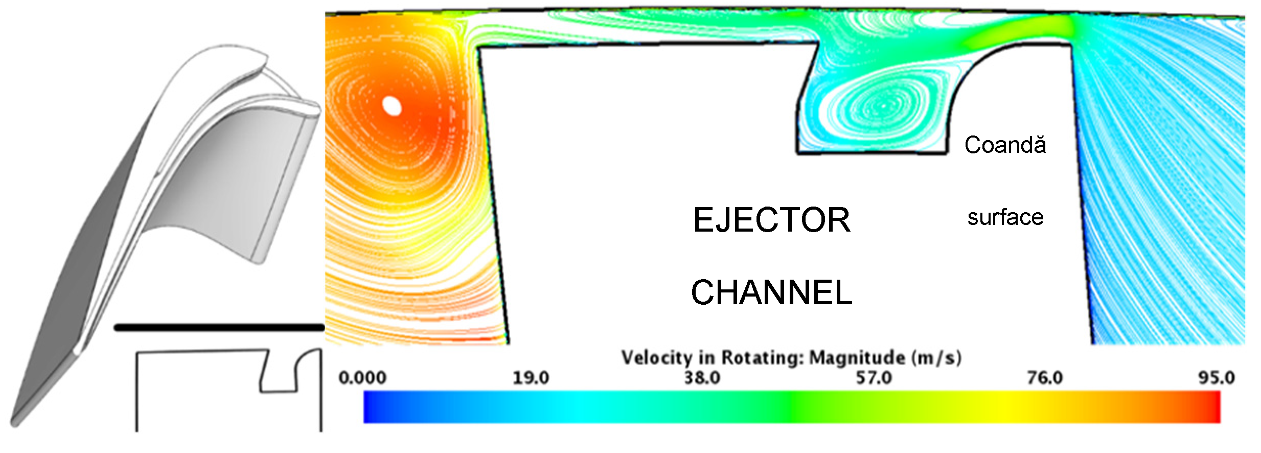
Figure 28.
ECI5 relative streamlines at x/Cax = 0.3.
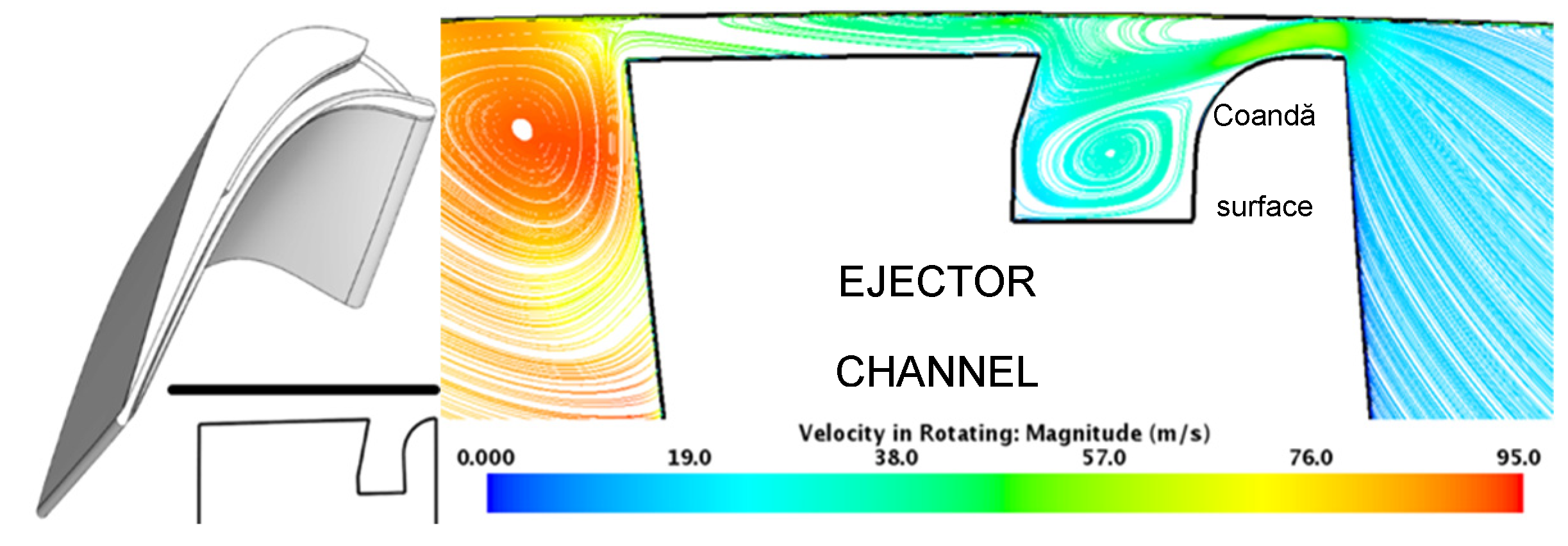
Figure 29.
ECI5n relative streamlines at x/Cax = 0.3.
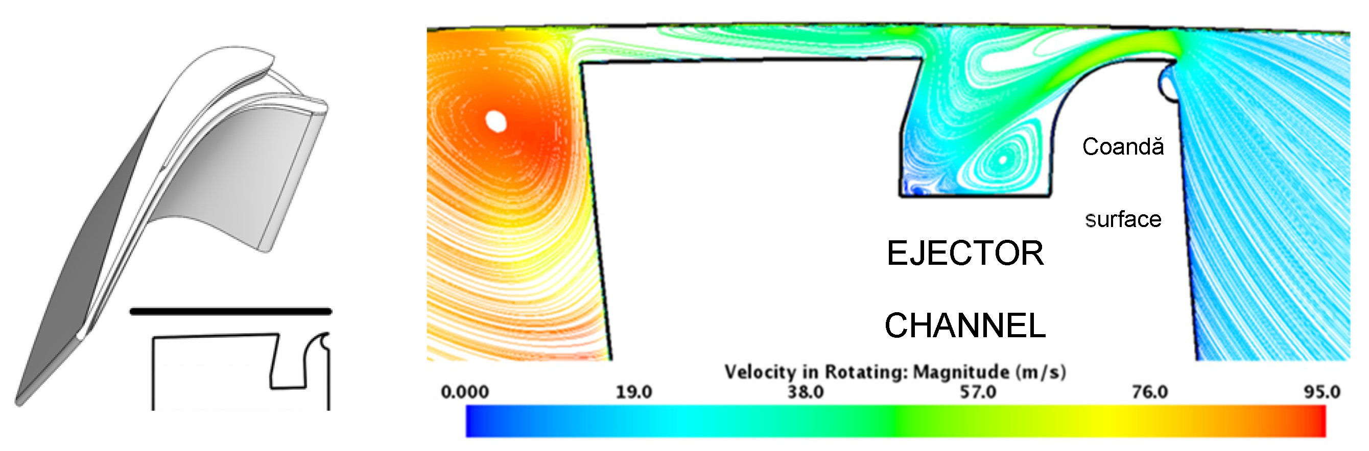
Figure 30.
ECI5n-HS relative streamlines at x/Cax = 0.3.
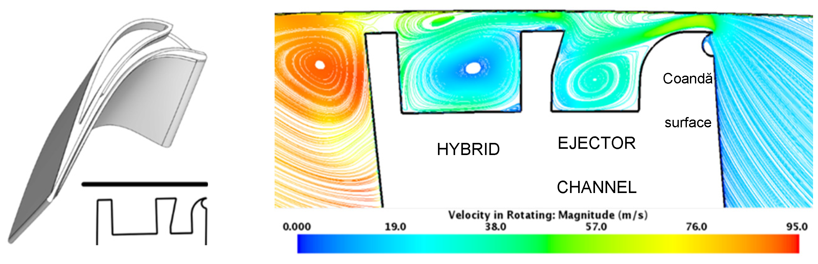
Figure 31.
ECI5n-HES relative streamlines at x/Cax = 0.3.
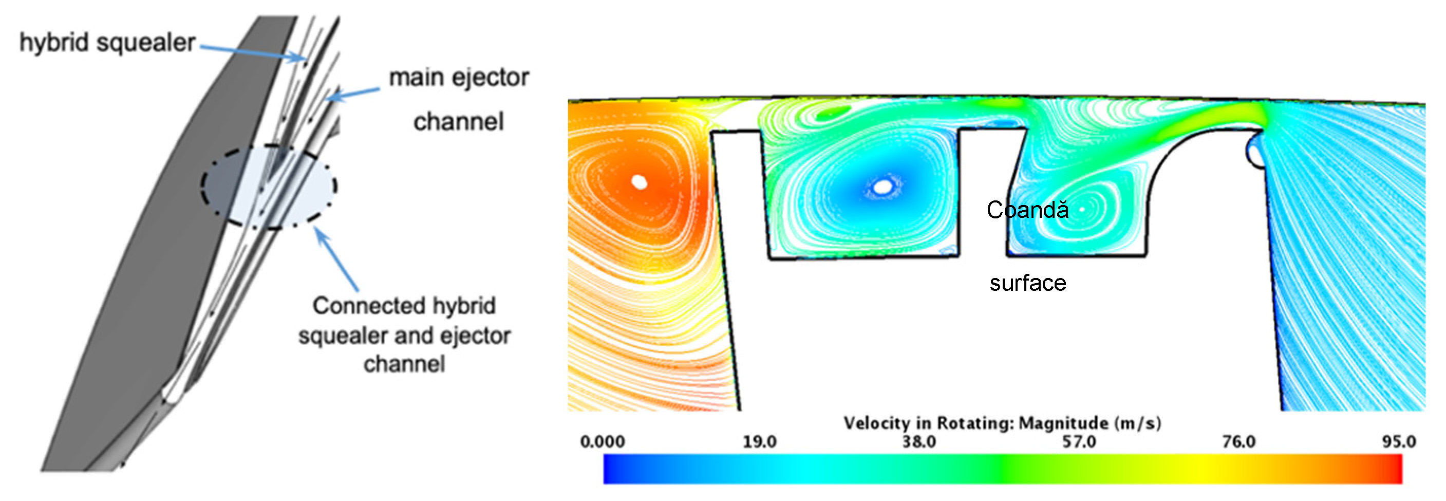
Figure 32.
ECI5n-OHES relative streamlines at x/Cax = 0.3.
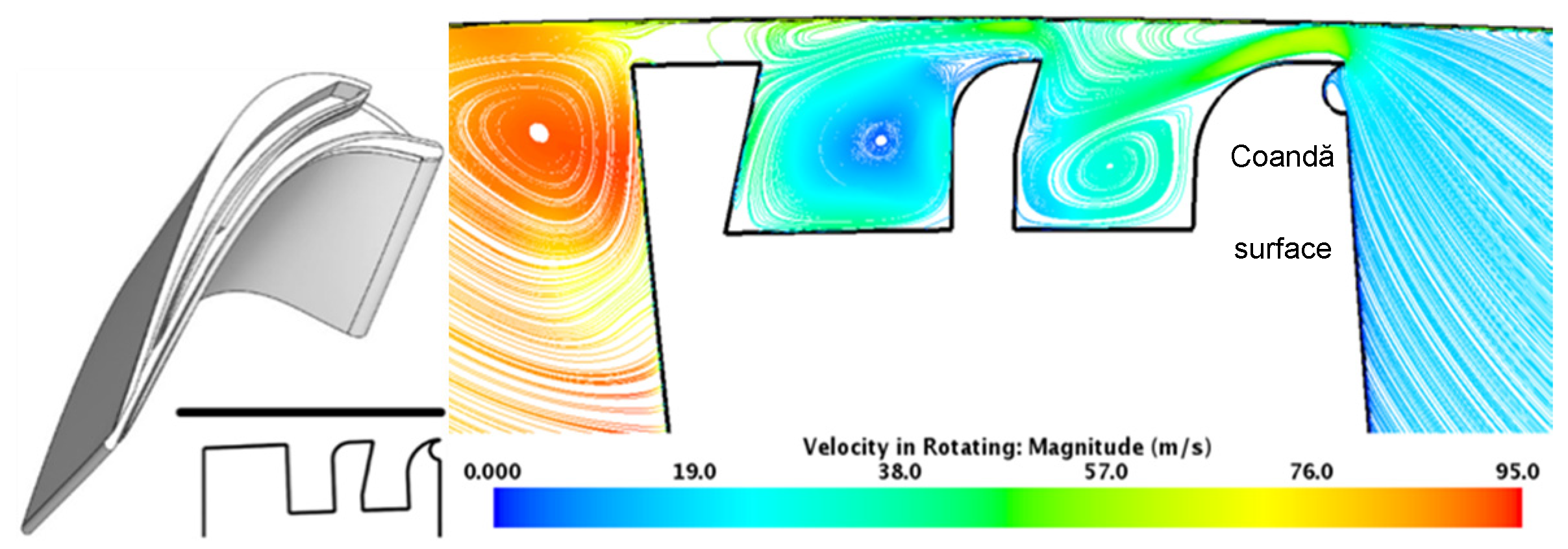
Figure 33.
D-ECI5n relative streamlines at x/Cax = 0.3.
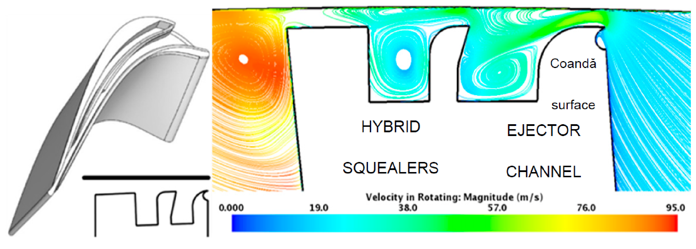
Figure 34.
D-ECI5n-HS relative streamlines at x/Cax = 0.3.
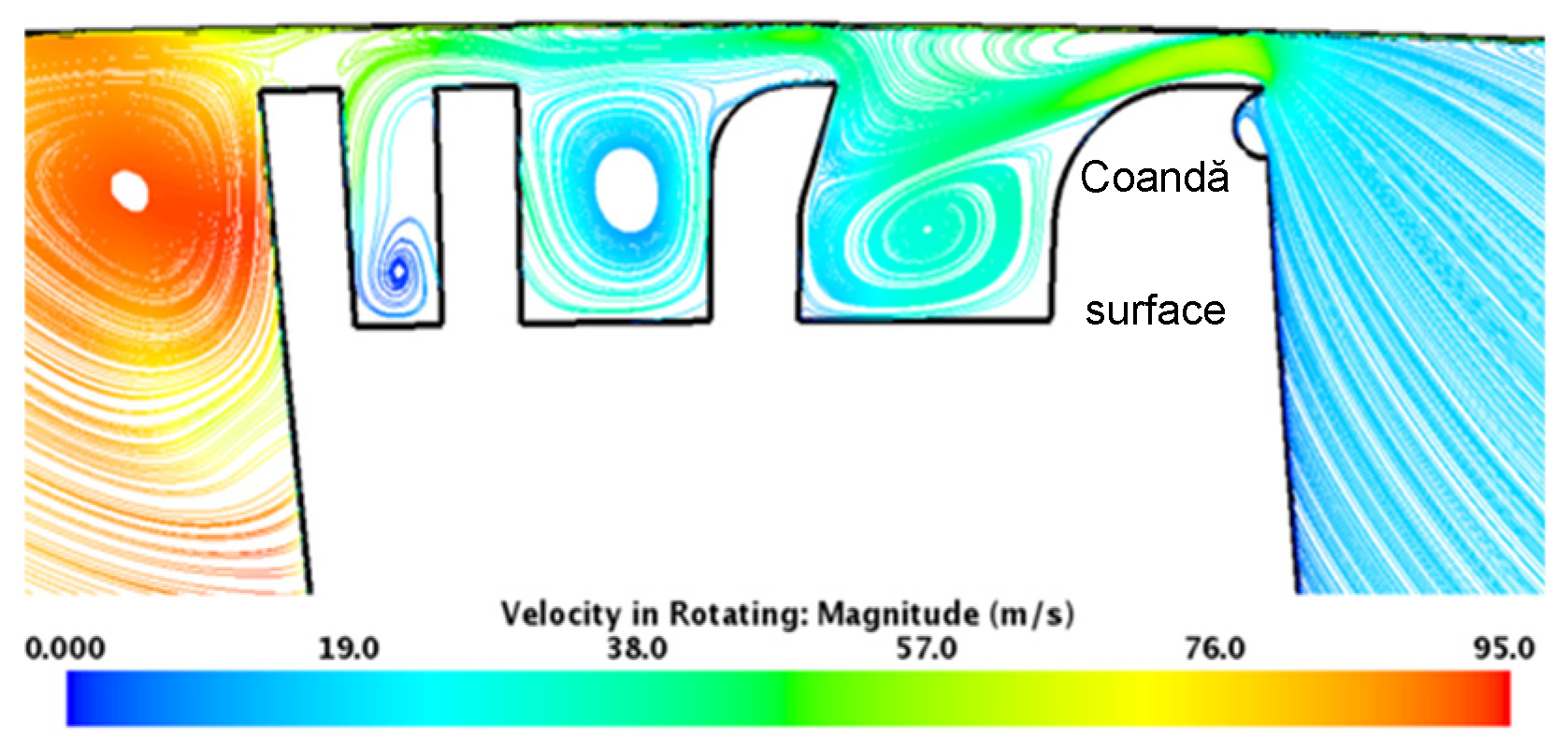
Figure 35.
T-ECI5n relative streamlines at x/Cax = 0.3.
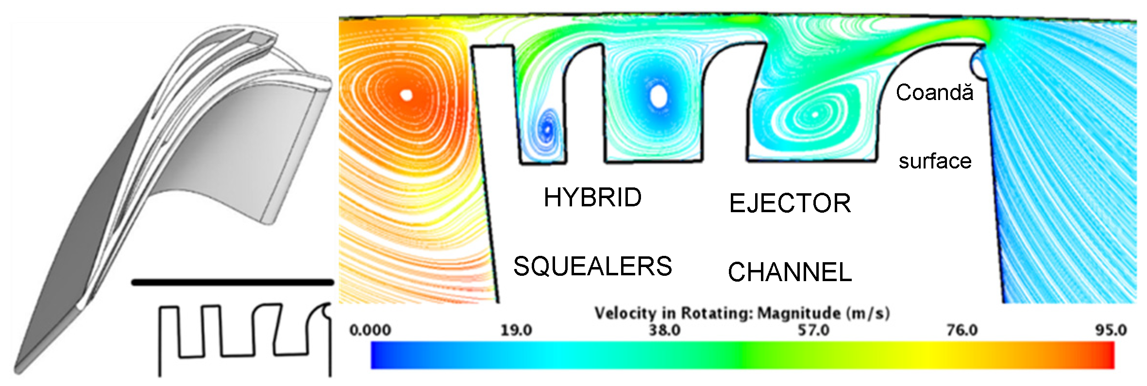
Figure 36.
EB5 relative streamlines at x/Cax = 0.3.
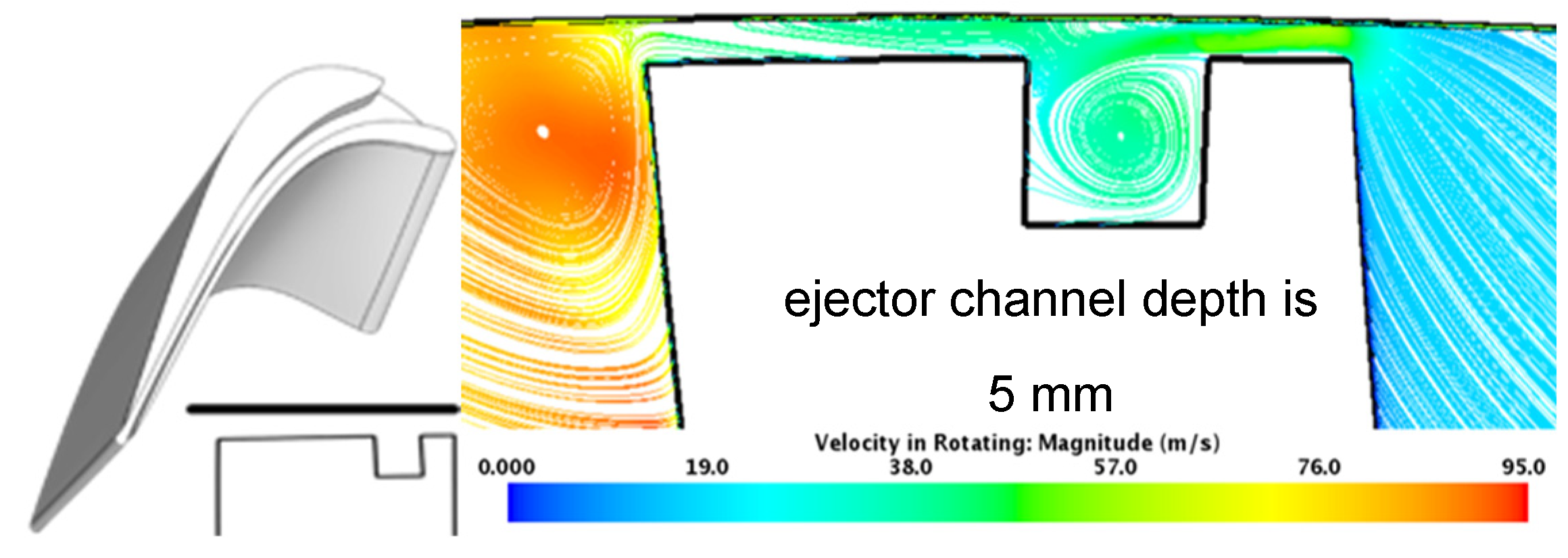
Figure 37.
Stage exit total pressure in the spanwise direction for the best four tip leakage mitigator design cases with (obtained 23 mm downstream of the trailing edge, nominal tip clearance is t/h=0.8% for all four designs).
Figure 37.
Stage exit total pressure in the spanwise direction for the best four tip leakage mitigator design cases with (obtained 23 mm downstream of the trailing edge, nominal tip clearance is t/h=0.8% for all four designs).
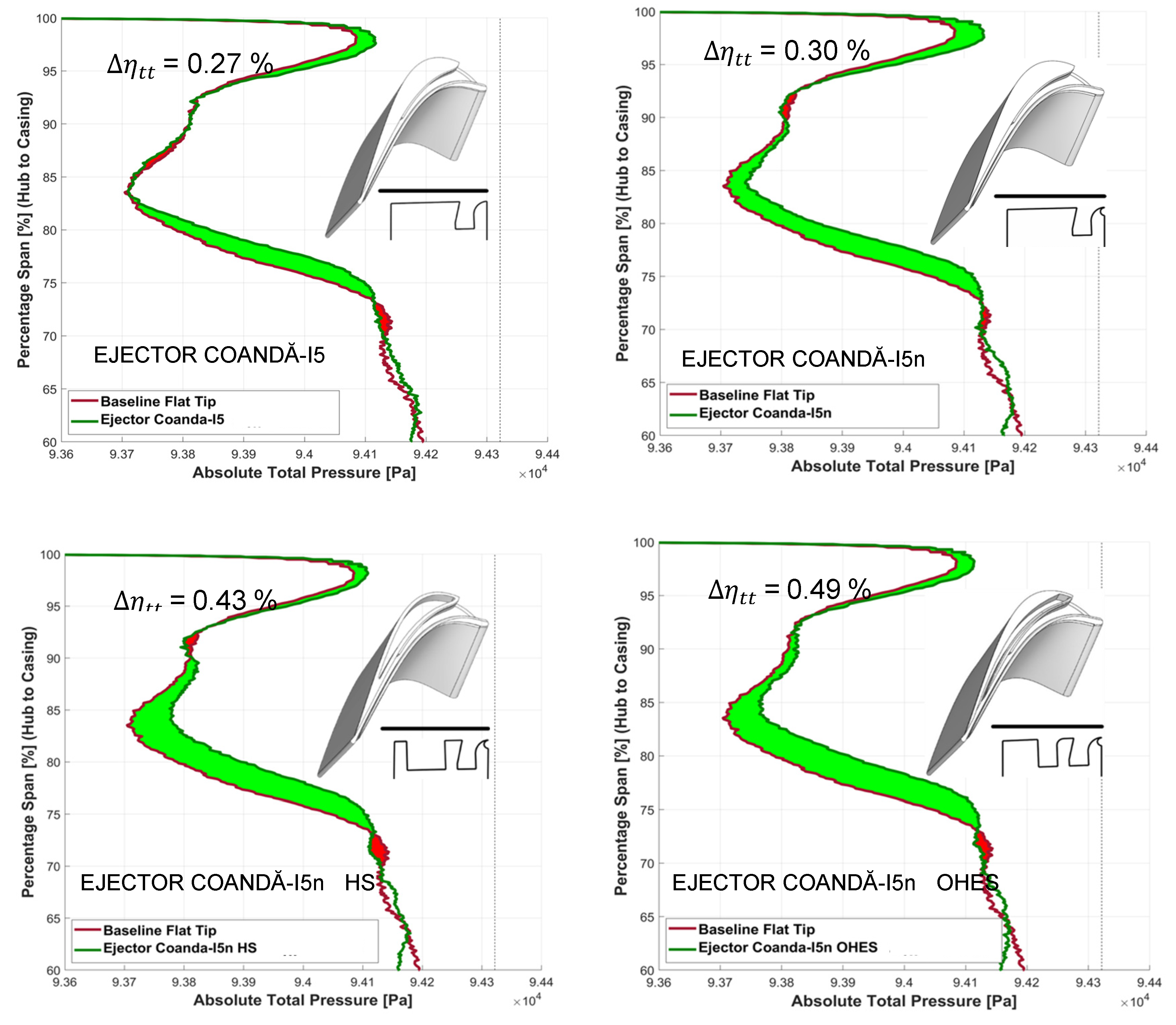
Figure 38.
(a) Percent change in leakage , and FOMTip for all designs compared to AFTRF baseline flat tip (arrows indicate selected cases).
Figure 38.
(a) Percent change in leakage , and FOMTip for all designs compared to AFTRF baseline flat tip (arrows indicate selected cases).
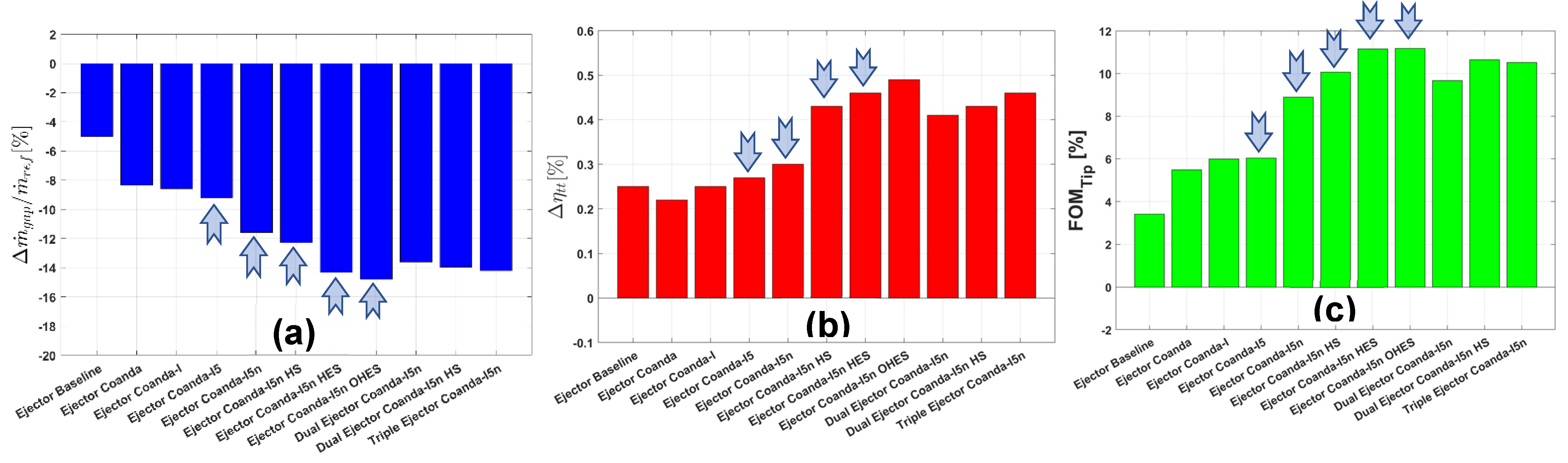
Figure 39.
The exchange rate between and FOMTip for all concepts compared to baseline Flat Tip (FT).
Figure 39.
The exchange rate between and FOMTip for all concepts compared to baseline Flat Tip (FT).
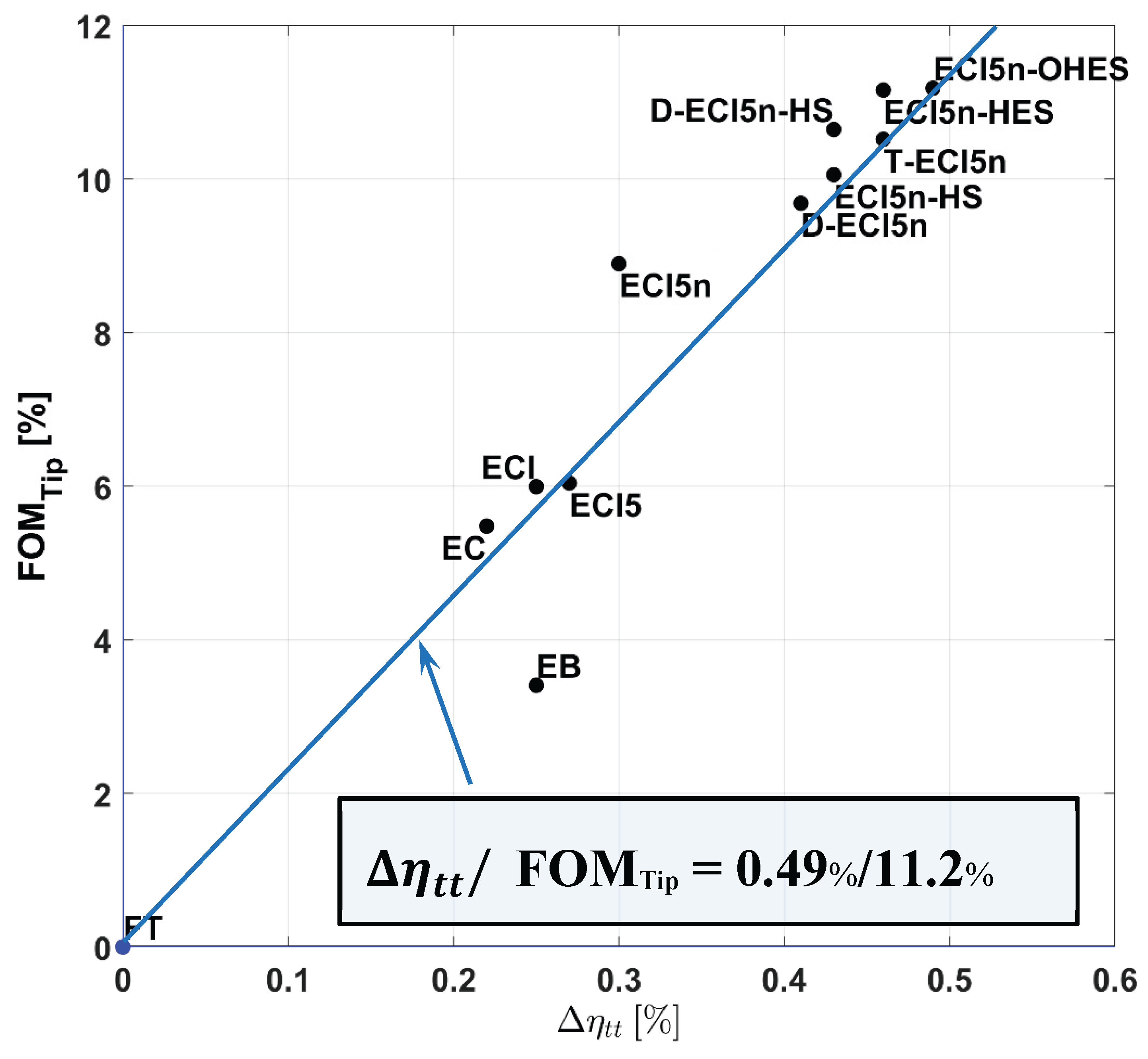

Table 1.
The AFTRF Performance Parameters.
| Inlet Total Temperature (K) | 289 |
| Inlet Total Pressure (KPa) | 101.36 |
| Mass Flow Rate(kg/s) | 11.4 |
| Rotational Speed(RPM) | 1333 |
| Total Pressure Ratio(/) | 1.0778 |
| Total Temperature Ratio(/) | 0.981 |
| Pressure Drop(mmHg); - | 56.04 |
| Power (KW) | 60.6 |
Table 2.
The AFTRF Design Parameters.
| Rotor Hub Tip Ratio | 0.7269 |
| Tip Radius (m) | 0.4582 |
| Blade Height h (m) | 0.1229 |
| Tip Relative Mach Number | 0.24 (max) |
| Nozzle Guide Vane | |
| Number | 23 |
| Mid-span axial chord (m) | 0.1123 |
| Turning angle (deg) | 70 |
| Reynolds number based on inlet velocity | 3~4 x |
| rotor-stator axial spacing at hub (mm) | 36.32 |
| Rotor Blade | |
| Number | 29 |
| Mid-span axial chord (m) | 0.0929 |
| Turning at tip angle (deg) Turning angle at hub (deg) |
94.42 125.69 |
| Tip clearance t/h | 0.8 % |
| Reynolds number based on inlet velocity | 2.5~5.0x |
Table 3.
A comparison of tip-gap mass flow rate, total-to-total isentropic efficiency, and FOMTip, for all tip designs (best designs are background-shaded).
Table 3.
A comparison of tip-gap mass flow rate, total-to-total isentropic efficiency, and FOMTip, for all tip designs (best designs are background-shaded).
| Concept | Tip Gap Mass Flow Rate |
Percent Change |
Total-to-Total Isentropic Efficiency |
(from Baseline FT) |
FOMTip |
|---|---|---|---|---|---|
| Flat Tip (FT) |
8.38 g/s | 0.00% | 89.44% | 0.00% | 0.00% |
| Ejector Baseline (EB) |
7.96 g/s | -5.01% | 89.69% | 0.25% | 3.41% |
| Ejector Coandă (EC) |
7.68 g/s | -8.35% | 89.66% | 0.22% | 5.48% |
| Ejector Coandă-I (ECI) |
7.66 g/s | -8.59% | 89.69% | 0.25% | 5.99% |
| Ejector Coandă-I5 (ECI5) |
7.61 g/s | -9.91% | 89.71% | 0.27% | 6.04% |
| Ejector Coandă-I5n (ECI5n) |
7.41 g/s | -11.58% | 89.74% | 0.30% | 8.90% |
| Ejector Coandă-I5n Hybrid Squealer (ECI5n-HS) |
7.35 g/s | -12.29% | 89.87% | 0.43% | 10.05% |
| Ejector Coandă-I5n Hybrid Ejection Squealer (ECI5n-HES) |
7.18 g/s | -14.32% | 89.90% | 0.46% | 11.16% |
| Ejector Coandă-I5n Optimized Hybrid Ejection Squealer (ECI5n-OHES) | 7.14 g/s | -14.80% | 89.93% | 0.49% | 11.18% |
| Dual Ejector Coandă-I5n (D-ECI5n) |
7.24 g/s | -13.60% | 89.85% | 0.41% | 9.68% |
| Dual Ejector Coandă-I5n Hybrid Squealer (D-ECI5n-HS) |
7.21 g/s | -13.96% | 89.87% | 0.43% | 10.65% |
| Triple Ejector Coandă-I5n (T-ECI5n) |
7.19 g/s | -14.20% | 89.90% | 0.46% | 10.52% |
| Ejector Baseline-5 (EB5) |
7.91 g/s | -5.61% | 89.60% | 0.16% | 3.61% |
Disclaimer/Publisher’s Note: The statements, opinions and data contained in all publications are solely those of the individual author(s) and contributor(s) and not of MDPI and/or the editor(s). MDPI and/or the editor(s) disclaim responsibility for any injury to people or property resulting from any ideas, methods, instructions or products referred to in the content. |
© 2025 by the authors. Licensee MDPI, Basel, Switzerland. This article is an open access article distributed under the terms and conditions of the Creative Commons Attribution (CC BY) license (http://creativecommons.org/licenses/by/4.0/).
Copyright: This open access article is published under a Creative Commons CC BY 4.0 license, which permit the free download, distribution, and reuse, provided that the author and preprint are cited in any reuse.


