
Submitted:
01 August 2025
Posted:
04 August 2025
You are already at the latest version
Abstract
Adverse pressure gradients are intrinsic to the flow behavior in compressors and are further ex-acerbated by secondary effects arising from rotor tip clearance flow interactions, a phenomenon common across various turbomachinery configurations, axial and radial. Tip clearance induces leakage flow, which leads to the formation of tip leakage vortices—a principal contributor to aerodynamic losses in axial compressors. These vortices exert a significant impact on both com-pressor performance and the operational stability range. Extensive prior research has demon-strated that passive casing treatments, particularly the implementation of axial slots, can sub-stantially enhance stall margin in axial compressors. The recirculating flow established within semi-circular axial slots acts to mitigate the strength of the tip leakage vortex by redirecting low-momentum leakage flow upstream of the rotor leading edge, thereby introducing a resistance mechanism that suppresses flow leakage through the clearance gap. Many existing studies on axial slot implementation focus predominantly on high-performance single-stage axial compressors. Consequently, there remains a gap in the literature regarding the application and performance implications of such treatments in multi-stage compressor systems. In the present study, a passive casing treatment employing axial slots was integrated into a multi-stage axial compressor. The slot geometry was selected based on recent experimental findings involving single-rotor configura-tions. The casing treatment was applied over the first rotor row in a three-and-a-half-stage (3.5-stage) axial compressor configuration, comprising an inlet guide vane (IGV) followed by three rotor-stator stages. Three-dimensional steady-state numerical simulations were conducted to investigate the aerodynamic effects of the axial slot treatment across various rotational speeds. The results obtained for the slotted configuration were compared against a baseline case featuring a smooth casing. The introduction of axial slots induced noticeable modifications to the internal flow structure, particularly in the tip region, leading to an improvement in overall compressor stability within the operating range between 85% to 100% of design speed. Stall margins improved 3.55% at design speed. Significant stall margin improvement occurred at 95% design speed with ΔSM of 11.24%. At 85% design speed, the efficiency starts to deteriorate and axial slots did not improve the stall margins with ΔSM of -1.03 %.
Keywords:
casing treatment
; axial compressor
; gas turbine
1. Introduction
Compressor designers must meet a range of performance requirements, among which two primary aerodynamic objectives are paramount: achieving high efficiency and ensuring sufficient stall margin throughout the turbomachine’s operational life. In high-performance compressors, the internal flow often encounters significant adverse pressure gradients due to the elevated pressure loading across each blade row. This can lead to boundary-layer separation on the suction side of the blades, occurring at various spanwise positions and resulting in unsteady flow phenomena.
Despite decades of investigation, the current understanding of flow instabilities and stall mechanisms in axial compressors remains incomplete. Even state-of-the-art numerical tools frequently fail to accurately predict stall onset. As highlighted by Day [1], after more than 75 years of focused research, a comprehensive understanding of compressor stall has yet to be achieved, underscoring the complexity of the phenomenon.
In addition to the inherent aerodynamic challenges, external factors—such as rising fuel costs and growing environmental concerns—continue to drive the development of gas turbine engines toward improved overall efficiency and reduced fuel consumption, as noted by Berdanier [2].
Berdanier further emphasizes that the latest generation of high-bypass-ratio turbofan engines, characterized by smaller axial compressor core diameters, poses additional design challenges. These include maintaining high efficiency and aerodynamic stability in multi-stage axial compressors operating with reduced tip clearance and elevated rotational speeds.
The reduction in engine core size results in smaller blade geometries, particularly in the rear stages of axial compressors. As engine cores become more compact, the corresponding flow passage areas decrease, and endwall losses become increasingly significant, accounting for a larger proportion of the overall aerodynamic losses, as noted by Berdanier [2].
Additionally, tip clearances do not scale proportionally with blade miniaturization due to manufacturing tolerances, design constraints, and the allowances required for transient operation and thermal expansion. Tip clearance exerts a substantial influence on turbomachinery performance, representing a dominant source of aerodynamic loss in axial compressors. Excessive tip clearances lead to deteriorated efficiency and a reduction in the operational range of the machine [2,3].
In the tip clearance region, the pressure differential between the pressure and suction sides of the blade drives a cross-flow known as tip leakage flow [4,5,6]. This flow interacts with the primary stream and gives rise to complex flow structures known as tip leakage vortices. Studies by Furukawa [7] and Wilke & Kau [8] have demonstrated that tip leakage vortices are critical contributors to the onset of stall in axial compressors.
The adverse pressure gradients inherent in compressor operation are further amplified by the effects of tip leakage vortices, which are prevalent in various types of turbomachinery, as described by Leitner et al. [9]. These vortical structures introduce unsteady flow behavior and localized loss mechanisms that degrade overall compressor performance.
A comprehensive understanding of tip leakage flow physics, particularly in multistage environments, is essential for optimizing compressor design. Improving off-design performance and achieving effective stage matching become increasingly complex as pressure ratios rise. This challenge is especially critical in the preliminary design phase of multistage axial compressors, as emphasized by Day [1].
The tip leakage flow also interacts with the main flow and other vortical structures, contributing to the formation and intensification of the tip leakage vortex. This vortex plays a significant role in the onset of compressor stall and surge phenomena [10]. Stall is characterized by flow separation on the compressor blades, which limits the operational range of the machine. As a result, both efficiency and performance are constrained under stall conditions.
There are two primary approaches to enhancing stall margin in axial compressors. The first approach involves active flow control technologies. These techniques typically inject flow into regions with low momentum or extract weak flows to reduce aerodynamic blockage. In some cases, both injection and extraction are employed simultaneously, as described by Culley [11].
In active systems, part of the flow mechanism—often referred to as a “surge avoidance controller”—is used as a backup mode to enhance operational safety. Under active control, the compressor can operate stably beyond the conventional surge line. This configuration, known as a hybrid system, is under investigation by Sheng et al. [12], but it remains far from practical implementation in industrial applications. Furthermore, challenges persist in detecting stall precursors and actuating bleed flows in real time to restore stable operation. Technologies such as Bleed Valve Control fall outside the scope of the present study.
Similarly, active casing treatments involving injection mechanisms near the blade tip region will not be addressed here. Despite their potential, many of these advanced control strategies have not transitioned to commercial engines due to their complexity, additional weight, and cost implications.
A second approach involves passive flow control through casing treatments (CT). Unlike active systems, passive CTs have no moving parts and are comparatively simpler to design, install, and manufacture. Examples of passive casing treatments include circumferential grooves and axial slots. These techniques were extensively studied in the 1970s and have recently regained attention due to their demonstrated ability to significantly improve stall margin with minimal degradation in efficiency.
Numerous casing treatment configurations have been proposed in the literature to enhance stall margin with minimal impact on overall machine performance [13,14,15,16]. Casing treatments work by obstructing leakage flow within the tip gap region, thereby modifying the local flow field to delay stall onset. However, each compressor design requires a tailored casing treatment to optimize its stall margin improvement potential.
The current availability of advanced Computational Fluid Dynamics (CFD) tools enables detailed investigations of three-dimensional flow structures within turbomachinery. Numerical simulations have been extensively employed to support the engineering decision-making process, particularly for evaluating geometric modifications to compressor casing treatments (CT). These CFD tools have facilitated significant advancements in turbomachinery design, fostering the development of innovative concepts aimed at reducing internal losses associated with complex flow fields.
It is important to note that the installation of CTs does not universally lead to improved stall margins. Therefore, the selection and configuration of CTs should be guided by insights from recent studies, with CFD simulations used as a key tool to evaluate expected improvements in operational stability, while minimizing efficiency penalties. As a result, substantial research efforts have been devoted to developing effective solutions for this engineering challenge [17].
In recent years, there has been increasing interest in the influence of CTs on enhancing stall margin in multistage axial compressors. Experimental studies have been conducted on multistage compressors, such as the two-stage axial compressor investigated by Rabe [18], and the four-stage DLR research compressor studied by Goinis [19]. This line of research has been significantly accelerated by improvements in CFD capabilities. Rabe employed a single-passage, steady-state numerical analysis focused on the first rotor to assess the effects of CTs on the overall compressor performance. Goinis utilized a computational domain that included the Inlet Guide Vanes (IGV), as well as the first rotor and stator, to analyze CT effects in a four-stage configuration.
The DLR study was conducted on an existing laboratory compressor to confirm whether the rotor operated as a tip-limited compressor, characterized by spike-type or wall-initiated stall mechanisms in the rotor tip region. The presence of a tip-limited stall behavior in the first stage is highly desirable for casing treatment implementation, as it tends to offer the greatest benefit.
Bruno Diaz conducted numerical investigations on a four-stage high-performance axial compressor, employing passive wall treatments in the form of axisymmetric circumferential grooves. Details of this work can be found in reference [20]. The author observed that applying circumferential groove-type CTs to the second stage did not yield significant benefits at rotational speeds above 60% of design speed (N60). This finding aligns with Rabe’s earlier conclusion [18] that the flow field of the first rotor predominantly determines the stall characteristics in two-stage compressors.
In the present study, axial slot-type passive wall treatments were implemented on the casing above the first rotor of the well-documented 3.5-stage axial compressor “74A” described by Steinke [21]. For this purpose, three-dimensional CFD simulations based on the Reynolds-Averaged Navier–Stokes (RANS) equations were conducted. These simulations were used to validate the smooth-wall case against experimental performance data and to assess the performance impact of the axial slot-type casing treatment.
2. Description of the Casing Treatment and Methodology
In the present study, an axial slot casing treatment (ASCT) was implemented in the casing above the first rotor row of a multistage axial compressor. The compressor under investigation is a 3.5-stage turbomachine operating in the transonic flow regime. Figure 1 presents the meridional view of the compressor analyzed in this work. Further details regarding the characteristics of the compressor can be found in the works of Steinke and Veres [21,22].
Figure 2 presents an isometric view of the axial compressor, highlighting the physical boundaries and the casing treatment, with y⁺ ≤ 1.1.
Among various configurations of variable geometry for the Inlet Guide Vanes (IGV) and stators, the most effective configuration, based on laboratory testing at 100% design speed—was selected, with resetting angles of 15 degrees for the IGV and 10 degrees for stators 1, 2, and 3.
Experimental data for this configuration indicated a rapid deterioration in compressor efficiency when operating below 85% of the design speed. In this off-design regime, the flow is dominated by separation, recirculation, reattachment, and strong unsteadiness.
As a result, Reynolds-Averaged Navier-Stokes (RANS) numerical simulations are not reliable below 85% of the design speed. In this region, predictions of surge margin, efficiency, and mass flow rate become increasingly inaccurate, and simulations often fail to converge.
Nonetheless, the enhancement of stall margin within the high-efficiency operating region of high-performance, transonic, multi-stage axial compressors continues to be a topic of interest in both academic and industrial research.
In the present study, only rotational speed lines equal to or greater than 85% of the design speed were analyzed to evaluate the influence of axial slots on stall margin performance.
Table 1 (adapted from Steinke [21]) presents the geometric parameters of the 3.5-stage axial compressor. The design speed is 16,042.3 rpm under standard ambient conditions (288.2 K and 1 atm), and the blade tip speed at Rotor 1 reaches approximately 431 m/s.
The solidity of Rotor 1 varies between 1.3 and 2.5, with an average of 1.7. The solidity of Rotor 2 ranges from 1.2 to 1.8, averaging 1.4, while Rotor 3 presents values between 1.2 and 1.5, with an average of 1.3. According to Greitzer [23], whose findings were experimentally validated, passive casing treatment tends to be more effective when rotor solidity exceeds 1.5. In such cases, blade loading is higher, and the stall initiation mechanism transitions from blade stall to wall stall. Greitzer’s research played a pivotal role in advancing the understanding of stall initiation mechanisms in axial compressors. By systematically varying rotor solidity, Greitzer demonstrated the ability to shift the stall inception mechanism between blade stall and wall stall.
In the present work, passive wall treatment is applied exclusively to Rotor 1, based on prior justification provided by Rabe [17] and Greitzer [23]. Given the low solidity values for Rotors 2 and 3, significant improvements in stall margin are not anticipated in the downstream stages.
The primary objective is to stabilize the flow near the tip region of Rotor 1 by energizing the boundary layer and reducing tip leakage flow (TLF). This approach aims to suppress the formation of the tip leakage vortex (TLV), thereby delaying flow separation and minimizing the propagation of flow disturbances to subsequent rotor stages.
The proposed configuration is a modified version of the standard casing treatment (CT) described by Lu et al. [24] and Brignole [25]. It consists of 84 axial skewed slots, corresponding to three axial slots per blade passage, as illustrated in Figure 3. The slot width remains consistent with the standard CT configuration. The number of slots was increased from 64 (in the standard configuration) to 84 to maintain proportionality with the increased tip diameter of Rotor 1, which was scaled from 0.380 m (standard CT) to 0.505 m (present CT), corresponding to three axial slots per passage.
The shape of a single cavity is a semi-circular slot with a rectangular opening surface. The axial length is approximately 66% of length of the axial rotor 1 tip chord. The axial overlap ratio Lex is defined by the ratio of the distance between the blade LE and the treatment TE to the rotor tip chord, which is used to determine the axial position of slots which is 33% of blade tip cord with value of 13.97 mm. The open area ratio (OAR) is defined as the ratio between the opening surface area of slots and the casing area in a single passage. Skew angle (SA) is defined as the angle at which the axial slot deviates from the normal outside the casing. Lex, OAR, and SA of the proposed casing treatment are 33% (corresponding 13.97 mm), 0.5, and 0◦.
Selection of skew angles of 0 degrees came from conclusions of Engels [26] who proposed simplifications of the complex axial slot model implemented in the first rotor of TP-400 engine and the validity of this approach was shown by the comparison with rig data.
Selection of axial slot casing treatment with 33% cord exposure came from Lu et al. study in 2006 [27], which was the highest stall margins obtained in the study. Nearly 21.43% stall margin improvement in terms of the corrected mass flow rate was achieved with 33.3% rotor blade tip axial chord exposure.
The casing treatment (CT) configuration consisted of three identical semicircular cavities per blade passage. These axial slots were positioned directly above the leading edge of Rotor 1 blades and oriented axially, with a standard circumferential lean angle of 0° in the direction of rotation. Due to the semicircular geometry, the slot depth was implicitly defined by the axial length. The tip chord of Rotor 1 measures approximately 42.3 mm, which is comparable to the tip chord length of the Darmstadt Transonic Compressor (DTC). However, the axial slot length employed in this study is shorter than that of the standard casing treatment used in the DTC, corresponding to approximately 66% of the Rotor 1 blade tip chord, i.e., about 28.3 mm.
A slicing interface was applied between the rotor mesh and the axial slot mesh to eliminate non-axisymmetric boundary conditions, enabling steady-state simulations for operating points relatively close to the design point.
It is anticipated that the flow within the axial slots will exhibit time-independent recirculation patterns. As a result, meaningful improvements in compressor stall margins can be predicted using steady Reynolds-Averaged Navier-Stokes (RANS) simulations, even though circumferential averaging between rotors and stators may not capture the inherently unsteady nature of the underlying flow structures.
The three-dimensional CFD solver will be used to characterize the flow field through a numerically approximated solution. The resulting compressor performance map will be synthesized and compared against experimental data. Subsequently, the CFD simulations with casing treatment applied to Rotor 1 will be used to evaluate performance differences between the smooth casing and the treated casing configurations. The stall margin improvements will be assessed for various operating conditions, specifically at corrected speed lines of N = 100%, N = 95%, and N = 85%.
3. Numerical Scheme Used for 3D Flow Calculations
The ANSYS® CFX version 19.2 solver was employed to perform numerical simulations based on the discretized three-dimensional Reynolds-Averaged Navier-Stokes (RANS) equations. The solver utilizes the finite volume method to discretize the governing equations. It was used to compute the flow field characteristics and subsequently evaluate the influence of the passive wall treatment on the axial compressor’s stall margin.
Steady-state simulations were carried out by solving the RANS equations. The Rhie-Chow interpolation scheme [28] was applied for the discretization of mass terms to prevent pressure-velocity decoupling. A high-resolution, second-order scheme was adopted for the discretization of the momentum equations. This scheme employs a Monotonic Upstream-centered Scheme for Conservation Laws (MUSCL) approach with limiter functions to dynamically adjust the discretization order in the presence of flow discontinuities. The two-equation k-ω Shear Stress Transport (SST) turbulence model, developed by Menter [29], was selected for eddy viscosity calculations due to its capability to accurately model both near-wall and free-stream turbulence characteristics.
At the compressor inlet, boundary conditions included specified total pressure, total temperature, turbulence intensity, and axial flow direction. The inlet guide vane (IGV) inlet conditions were set with a constant total pressure of 101,325 Pa and a total temperature of 288.15 K. Advection terms were discretized using the high-resolution scheme described earlier. Solid boundaries were modeled as adiabatic with a no-slip condition.
Mixing-plane interfaces were established between blade rows to simulate the interaction between rotating and stationary components. Rotational periodicity was enforced in the blade-to-blade direction to reduce computational costs, enabling simulation of a single passage per blade row rather than the full annulus geometry. This modeling approach is widely accepted and has been shown to yield accurate results near the design point, as reported by Liu, Ju, and Zhang [35].
For simulations involving casing treatment, a frozen rotor interface was defined between Rotor 1 and the axial slot region to accommodate the relative motion between these zones. At the outlet boundary, the spanwise distribution of static pressure was prescribed based on the radial equilibrium equation.
The compressor performance map was constructed using results from steady-state simulations. For each rotational speed, a speed line was generated by incrementally increasing the static back pressure at the compressor outlet, starting from a low value (near the choke condition) [30] and progressing until the numerical solution failed to converge, this is an indicative of stall onset. This non-convergence criterion has been adopted in previous studies [31,32], recognizing that the stall point is characterized by highly unsteady flow behavior that is incompatible with the steady-state boundary conditions applied here.
Steady-state convergence in simulations with casing treatment may also indicate an extended operational range and increased stall margin for the axial compressor. The same stall detection criteria used for the smooth casing configuration were applied to the treated cases. Numerical stall was identified by diverging mass flow, a monotonic decrease in total pressure ratio and efficiency, or failure to converge within a static back pressure variation of 1%, consistent with the methodology used by Wilke and Kau [33] and Engels [26].
Convergence of the RANS equations was monitored using the decay and stabilization of Root Mean Square (RMS) residuals. Acceptable convergence was achieved when RMS residuals for continuity fell below 10−4, and those for momentum fell below 10−3. Additionally, global imbalances in continuity, momentum, and energy across the computational domain remained under 0.01(< 1%). Figure 4 presents the RMS residuals for the smooth wall case. Other monitored parameters included pressure ratio, inlet and outlet mass flow rates (plotted as values/10 for clarity), compressor efficiency, and inlet-outlet mass imbalance, as illustrated in Figure 5.
4. Mesh Generation and Its Evaluation
Unstructured meshes composed of tetrahedral elements were generated using the commercial software ICEM CFD version 19.2 developed by ANSYS®, to discretize the fluid domain of the compressor (both physical and computational domains). To accurately resolve the near-wall flow and capture the viscous effects of the boundary layer, prism layers were applied to all solid surfaces. Figure 6 illustrates a cross-sectional view of the axial slot mesh, highlighting the unstructured tetrahedral elements and the wall-adjacent prism layers, which enhance resolution of the boundary-layer flow—a critical requirement for the numerical treatment of convective terms in the momentum equations.
Each blade row, including rotors and stators, was meshed independently to ensure mesh quality and to allow for localized refinements. Additionally, the axial slots were meshed separately to avoid introducing non-axisymmetric interfaces with the Rotor 1 shroud surface. Figure 7 presents the axial slot mesh superimposed above the Rotor 1 mesh, illustrating the interface strategy employed.
The independent meshing of each component offers several advantages, including greater flexibility in mesh refinement, easier control over key meshing parameters, and simplification of mesh modifications and treatment implementation. This modular approach also facilitates the application and integration of the axial slot casing treatment mesh onto the Rotor 1 domain.
As previously mentioned, a single-passage fluid domain was simulated for each blade row to reduce computational cost. Periodic boundary conditions were imposed in the circumferential (blade-to-blade) direction, which is a widely adopted practice in turbomachinery CFD to achieve computational efficiency while maintaining acceptable accuracy.
A transitional slice was employed to interface the casing treatment (CT) region with the rotating domain. The slice thickness corresponds to 3% of the blade tip clearance height, consistent with the configuration adopted by Lu et al. [34]. The lateral boundaries of both the passage and the slice were modeled using periodic boundary conditions to ensure consistent circumferential periodicity.
To adequately resolve the boundary layer and capture near-wall flow phenomena, grid refinement was applied in the vicinity of solid surfaces. The first grid point off the wall was positioned at 1.0×10⁻⁷ m from the blade and endwall surfaces, yielding a dimensionless wall distance of y⁺ < 1.1. This resolution ensures that the viscous sublayer is fully captured without the need for wall function approximations, thereby enhancing the accuracy of turbulence modeling near walls.
The computational domain outlet was positioned 0.11681 m downstream of Stator 3 trailing edge (TE), consistent with the extension tested in the experimental facility. In this region, a progressively coarsened grid was employed to reduce numerical cost while preserving flow accuracy. A non-reflective boundary condition was applied at the outlet to suppress artificial wave reflections and ensure physical outflow behavior.
The frozen rotor approach was adopted at the Rotor 1/slice interface to model the interaction between the rotating and stationary components, while mixing plane interfaces were used for all other rotor–stator interfaces to enable steady-state simulations. This approach facilitates the circumferential averaging of flow properties across adjacent blade rows, allowing efficient yet reliable predictions of time-averaged flow fields.
To verify mesh independence of the numerical results for smooth wall cases, four distinct unstructured grids were generated. Table 2 summarizes the main characteristics of these meshes. In all cases, the dimensionless wall distance y⁺ was maintained below 1.1, ensuring adequate resolution of the near-wall viscous sublayer.
The smooth wall compressor performance map at design-point rotational speed (N = 100) was obtained through numerical simulations using the four different mesh configurations, as shown in Figure. 8. The pressure ratio (PR) and mass airflow are normalized values in the Figure 8. Reference values are: PR=4.0 and mass airflow=29.71 kg/s. The overall behavior and predicted values of the smooth wall performance curves were found to be in close agreement across all four meshes, indicating mesh-independent results up to static pressure outlet of 320 kPa.
Grid refinement study involves performing the simulation on three successively finer grids. The method examining numerical convergence of CFD simulations is presented by Celik [35] with use of Grid Convergence Index (GCI) as estimative of grid refinement error.
Grid Convergency Index (GCI) methodology was applied over smooth wall compressor performance curves presented in Figure 8. The methodology provides 5% uncertainty and discretization errors (GCI) within 5%.
The refinement study selected 3 distinct meshes (Mesh 2, 3 and 4) and results are presented on Table 3.
The variable nomenclatures used in the Table 3 are based on the methodology presented by Celik. N are number of nodes of each simulation model, r is refinement ratio which is the cubic root of number of nodes ratio, φ is variable of interest which is the compressor pressure ratio (PR), p is the local order of accuracy and “e” is the relative error of variable φ which in this case is pressure ratio (PR). GCI is the estimative error of fine grid (Mesh 3) compared to high fine grid (Mesh 4).
The selection of fine mesh (Mesh 3) as reference compared to high fine mesh (Mesh 4) provided maximum discretization error of order of 2.79 % at outlet pressure of 325 kPa.
The GCI study for smooth wall compressor configuration drives the selection of Mesh 3 (fine mesh) as reference for the subsequent simulations due to its balance between computational effort, mesh refinement verification and solution accuracy validated with experimental data in section 5 of this paper.
The compressor performance map with axial slots casing treatment at design-point rotational speed (N = 100) was obtained through numerical simulations using the three distinct mesh configurations, as shown in Figure 9.
The pressure ratio (PR) and mass airflow are normalized values in the Figure 9. Reference values are: PR=4.0 and mass airflow=29.71 kg/s. The overall behavior and predicted values of the axial slots casing treatment performance curves were found to be in close agreement across all three meshes, indicating mesh-independent results up to static pressure outlet of 320 kPa.
The grid refinement study methodology presented by Celik [35] was also used to verify the mesh independency of numerical results for axial slots compressor casing treatment configuration. The independency mesh study was applied in these three distinct unstructured grids to define the grid refinement level and to select the appropriate mesh, ensuring numerical accuracy while minimizing computational cost.
Table 4 summarizes the main characteristics of these meshes. In all cases, the dimensionless wall distance y⁺ was maintained below 1.1, ensuring adequate resolution of the near-wall viscous sublayer.
Grid Convergency Index (GCI) methodology provides 5% uncertainty and discretization errors (GCI) within 5%. The grid refinement study results of 3 distinct meshes (Mesh 5, 6 and 7) are presented on Table 5. The selection of medium grid (Mesh 6) as reference compared to fine mesh (Mesh 7) provided discretization error of order of 3.69 % at compressor static pressure outlet of 250 kPa. Other static pressure outlet conditions, the discretization error for pressure ratios were less than 1.2% up to outlet static pressure of 320 kPa.
The GCI study for axial compressor with axial slots casing treatment configuration drives the selection of Mesh 7 (fine mesh) as reference for the subsequent simulations due to its balance between computational effort and acceptable discretization error in a CFD simulation.
Mesh 7 (fine grid) is the combination of Mesh 3 (fine grid) from smooth wall axial compressor model with addition of axial slots compressor casing model in the fine grid level of refinement.
5. Validation of CFD Simulations with Experimental Data of Multi-Stage Axial Compressor (Smooth Wall at 100% Speed Line)
Following the 3D flow simulations to generate the compressor map for the smooth wall configuration, the numerically predicted results were compared with the available experimental data for the same configuration [21]. The comparisons between experimental and predicted compressor performance are presented in the figures below.
For the smooth wall casing, the stall point is overpredicted by the simulation. In regions of higher mass flow, the predicted total pressure ratios are consistently lower than the experimental values. This discrepancy is primarily attributed to the overprediction of blade boundary layer and endwall losses by the CFD model. While the overall trends of the predicted total pressure ratio curves, both with and without axial slot casing treatment, generally follow the experimental data at higher mass flow rates, notable deviations occur near the stall point. Specifically, the experimental pressure ratio curve tends to plateau and then slightly decrease near stall, whereas the numerical predictions display a similar profile but with a lower overall pressure ratio.
Regarding isentropic efficiency, only minor discrepancies are observed between simulation and experiment. These differences may stem from limitations in the turbulence model employed and/or experimental uncertainties, particularly due to the measurement of small temperature rises.
A relevant study by Liu et al. [36] conducted 3D CFD simulations of the NASA 3.5-stage axial compressor 74 using both in-house Parallel RANS and URANS solvers, as well as the commercial software NUMECA, under identical meshing conditions. Their results were benchmarked against the experimental dataset provided by Steinke [21]. In the present work, the CFD simulations using ANSYS® CFX RANS version 19.2 for the smooth casing at the design speed line (N = 100%) were compared against the same experimental reference. The resulting compressor maps (total pressure ratio vs. mass flow rate and isentropic efficiency vs. mass flow rate) are shown in Figure 10 and Figure 11. While good agreement is observed over most of the operating range, deviations become more pronounced under highly throttled conditions near the compressor outlet, where static pressure is elevated.
Another possible explanation for the deviation from experimental data in the high-pressure ratio region lies in the modeling of the stators within the numerical simulations. In the laboratory-tested axial compressor, the stators are mounted using a cantilevered construction, with the stator vanes attached to the compressor casing and a clearance present at the hub. The magnitude of this stator hub clearance is comparable to that of the rotor tip clearance.
In the present simulations, ideal stators without hub clearance were modeled, which may have contributed to the observed discrepancy. A hub vortex originating from the stator region was identified in the simulations, and a similar phenomenon was also reported by Liu et al. [36] for stators 2 and 3.
Interestingly, the presence of hub clearance in stators may have a beneficial effect on compressor performance. According to Lee [37], hub leakage can suppress hub vortex development, thereby improving overall compressor efficiency. This contrasts with the detrimental effect of rotor tip leakage, which enhances the formation of tip leakage vortices and impedes flow near the rotor tip region.
6. Results
To compare the performance of the passive wall treatment against the reference smooth wall case across different speed lines, the following equation was employed to quantify the variation in compressor stall margin:
The compressor map for the smooth wall case was calculated through 3D flow CFD simulations, extending up to the last convergence point before numerical divergence, which represents the physical stall conditions. Subsequently, the axial slot wall treatment at the casing of the first rotor row was simulated, and the compressor maps with casing treatment (CT) were generated up to the stall condition. The variation in stall margin was then calculated using Equation 6.1, with mass flow and the respective pressure ratio at the compressor outlet at the last convergence point, comparing both smooth wall and CT conditions.
6.1. Performance Map at Speed Line 100%N (N100) – with Axial Slots
6.2. Performance Map at Speed Line 95%N (N95)– with Axial Slots
The stall margin was improved with axial slots, and the results were compared with simulations without axial slots at a corrected speed line of 95% N (16,042.3 rpm). However, deviations from the experimental results were observed at high throttling static pressures at the outlet for both 3D CFD simulation models, as shown in Figure 14 and Figure 15.
6.3. Performance Map at Speed Line 85%N (N85) – with Axial Slots
No improvement in stall margins was observed with axial slots compared to simulations without axial slots at the corrected speed line of 85% N (16,042.3 rpm). However, deviations from the experimental results were noted at high throttling static pressures at the outlet for both 3D CFD simulation models, as shown in Figure 16 and Figure 17. A marginal improvement in efficiency of 0.792% was observed.
6.4. Stall Margins Calculations of Axial Compressor with Axial Slots CT
Table 6 shows the variation of (airflow close to stall), PR (pressure ratio), ηisen,peak (isentropic efficiency peak), and ΔSM or SMI (stall margin improvement) with respect to the smooth wall case at different corrected rotational speeds for the axial slots created on the casing of the first rotor blade row. Significant improvements in stall margins with the axial slots were observed at 95% N (16,042.3 rpm), along with an increase in efficiency. However, at 85% N, no improvement in stall margins was observed. A marginal gain in efficiency was noted with the axial slots.
6.5. Meridional Pressure Distributions of Axial Compressor With and Without Axial Slots CT
Figure 18 shows the meridional pressure distribution of the axial compressor (without CT) at 95% N, with an outlet static pressure of 285 kPa (near stall).
Figure 19 presents the meridional pressure distribution of the axial compressor with axial slots implemented in the R1 casing at 95% N and an outlet static pressure of 295 kPa (near stall). No significant difference in pressure distribution is observed in the meridional plane in the rotor 1 region. But it is observed more pressure recovery in the stator 1 outlet for Axial Slot casing treatment.
6.6. Mach Number Distributions of Multi-Stage Axial Compressor With and Without Axial Slots CT
Figure 20 and Figure 21 compare the Mach number contours at 95% N for the smooth wall configuration and the axial slot casing treatment. It is observed that shock waves are weaker with casing treatment compared to a smooth casing. Axial slots casing treatment improved compressor stability by reducing the severity of shock wave interactions. Also, the introduction of axial slots reduces the penetration of the tip leakage vortex into the blade passage mitigating the effects of tip leakage vortex. The reduction of tip leakage vortex contributes to enhanced flow stability in the blade tip region, thereby delaying the onset of compressor stall.
Figure 22 and Figure 23 compare the Mach number contours at 95% N for the smooth wall configuration and the axial slot casing treatment at 30% span from hub. The shock wave interactions are observed from 30% span up to Rotor 1 axial compressor shroud. Also, shock is observed at approximately 30% span from the hub in Stator 1 and subsequent stages, which may be linked to boundary-layer thickness effects in the stator’s hub region. However, the shock waves are weaker with casing treatment compared to a smooth casing even at 30% span.
It is concluded that axial slots casing treatment improved compressor stability by reducing the severity of shock wave interactions also in the stator 1. Also, the introduction of axial slots reduces the effects of tip leakage vortex into the blade passage mitigating the effects of tip leakage vortex. The reduction of tip leakage vortex contributes to enhanced flow stability in the stator 1 passage thereby delaying the onset of compressor stall.
6.7. Relative Pressure Distributions over Passage Rotor 1 of Multi-Stage Axial Compressor (Smooth Casing and with Axial Slots)
At 95% N, Figure 24 presents pressure contours in blade-to-blade planes under near-stall conditions. With the incorporation of axial slots, the low-pressure region associated with the tip leakage vortex (TLV) is noticeably reduced. The flow enters the slots, where vortices are generated, mitigating the leakage effect between blade surfaces. The flow recirculating within the slots re-enters the mainstream at a more forward axial position, interacting with the TLV, as illustrated in Figure 25. This interaction weakens the TLV, delaying stall onset and thereby extending the compressor stall margin.
6.8. Streamlines Inside Axial Slots over Rotor 1 Multi-Stage Axial Compressor
The recirculation effect within the axial slot casing treatment, as observed in the experimental validation presented by Brignole, Danner, and Kau [25], was confirmed in the present multi-stage axial compressor configuration with casing treatment applied to the Rotor 1 casing, as illustrated in Figure 26.
Streamline visualization feature of post processing software was used to plot the streamlines in the Figure 26. Initial flow seed was a semi-circle area installed in the second axial slot as shows in the gray color. Figure 27 presents initial flow seed in the line installed in the second axial slot. Axial line segment seed is represented by black color. Streamlines departing from this starting area or line inside slots are low speed colors and that streamlines get out from the leading edge of slots in the yellow streamlines (high speed colors). The streamlines originating from this region reveal that the flow exits through the leading edge of the slot, as indicated by the yellow streamlines. Due to periodic symmetry, these streamlines re-enter the computational domain and continue downstream toward the subsequent compressor stages.
7. Conclusions and Future Work
Improvements in the design margins of a multistage, high-performance axial-flow compressor were achieved, even in the context of highly optimized transonic blade designs. The results presented in this study demonstrate a reasonable enhancement in stall margin at 100% of the corrected rotational speed and a significant improvement at 95%N. However, no improvement in stall margin was observed at 85%N.
Despite these gains, compressor efficiency did not improve, which is consistent with the findings of researchers such as Goinis, Voss, and Nicke [38], and Goinis, Voss, and Aulich [39]. Their studies indicate that casing treatment (CT) is effective in enhancing stall margins, but not in increasing overall efficiency when the blade design is already optimized. This highlights the performance versus efficiency trade-off in axial compressor design. The major challenge in such designs is to enhance pressure ratio and stall margin while maintaining overall machine efficiency.
It is possible that for the multistage axial compressor 74A, no gains in efficiency were observed because the CT may increase entropy generation. Therefore, the focus should be on evaluating the potential improvements in stall margins. This study contributes by providing insights into the flow mechanisms in the rotor tip region that facilitate improvements in stall margin in high-performance compressors.
The present study focused on the axial compressor 74A, optimized for maximum efficiency at the design speed of 16,042.3 rpm, with inlet guide vane (IGV) set at 15°, and stators 1 through 3 all set at 10°. The maximum efficiency obtained from CFD simulations was approximately 83.8% at design speed, which exceeds the original design target of 79.9%. In laboratory experiments, after resetting the IGV and stator angles for maximum performance, a peak adiabatic efficiency of approximately 86% was recorded at design speed.
CFD simulations in this study yielded an adiabatic efficiency of 85% at 95%N, which aligns with the value obtained through NASA’s mean-line flow analysis for the same compressor, as reported by Veres [22] in 2009. The NASA mean-line tool, calibrated with Steinke’s [21] data for compressor 74A, incorporates rotor efficiency and stator loss coefficients at the design point as inputs. Off-design performance is calculated using models within the code, based primarily on rotor incidence levels.
Laboratory tests reported an adiabatic efficiency of 87.5% at 95% of design speed. The difference of 2.5% between the experimental and CFD values remains unexplained. However, recent research on multistage axial compressors with cantilever stator constructions suggests that hub rotation may positively influence hub leakage flow, potentially improving efficiency, as demonstrated by Zhang [40]. It is plausible that the unusually high efficiencies observed in the experimental tests are attributed to the stator cantilever design in compressor 74A.
Stator hub vortices were observed in this study (which assumes ideal stators with no hub clearance), as well as by Liu et al. [36] for stators 2 and 3. According to Lee [41] and Si [42], compressor efficiency can be improved by hub leakage, which reduces the intensity of hub vortices—contrary to tip leakage, which increases the strength of tip leakage vortices and restricts airflow near the rotor tips.
At the design point and under steady-state operation, compressor 74A exhibits elevated velocities near the tip of rotor 1. Additionally, a pronounced shock is observed at approximately 30% span from the hub in stator 1 and in subsequent stages. This phenomenon may be associated with boundary layer thickness effects in the stator hub region. Hub leakage in the stators could influence the boundary layer development in this area.
For future work, it is recommended to perform 3D CFD simulations of compressor 74A with axial slot casing treatments and varied stator clocking to better understand the influence of stator angular positioning on stall margin improvement. Furthermore, investigating the effects of hub clearance in stators could help clarify the efficiency gains observed experimentally, particularly the measured adiabatic efficiency of 87.5% at 95% of nominal rotational speed.
Acknowledgments
The authors would like to thank the ITA (Aeronautics Institute of Technology) Department of Turbomachines for the support and infrastructure provided during this research work; as well as the Coordenação de Aperfeiçoamento de Pessoal de Nível Superior (CAPES - Higher Education Improvement Coordination); the Fundação de Amparo à Pesquisa do Estado de São Paulo (FAPESP - São Paulo Research Foundation); and the Conselho Nacional de Desenvolvimento Científico e Tecnológico (CNPq - Brazilian National Council for Scientific and Technological Development).
Conflicts of Interest
The authors declare no conflicts of interest.
References
- Day I. J., 2016, “Stall, Surge and 75 years of Research,” ASME GT2015-44109. [CrossRef]
- Berdanier, Reid A., Toward Understanding Tip Leakage Flows in Small Compressor Cores Including Stator Leakage Flow, NASA, NASA/CR 2017-219687. https://ntrs.nasa.gov/api/citations/20170011073/downloads/20170011073.pdf.
- Guinet, C.; Streit, A.; Kau, H. P.; Gummer, V., Tip Gap Variation on a Transonic Rotor in the Presence of Tip Blowing. Dusseldorf, Germany. ASME, 2014. Paper No. GT2014-25042. [CrossRef]
- Inoue, M.; Kuromaru, M., Structure of Tip Clearance Flow in an Isolated Axial Compressor Rotor. Journal of Turbomachinery, v. 111, n. 3, p. 250, 1989. [CrossRef]
- Yamada, K.; Furukawa, M.; Inoue, M.; Funazaki, K., Numerical Analysis of Tip Leakage Flow Field in a Transonic Axial Compressor Rotor. In: Proceedings of the International Gas Turbine Congress 2003. Tokyo, 2003. p. 1-8.
- Diaz, R. B.; Tomita, J.T.; Bringhenti C.; Silva, D. T.; Cavalca, D. F., An Evaluation of Passive Wall Treatment with Circumferential Grooves in a High-Performance Multi-Stage Axial Compressor. ASME, GT2022-83100, V10AT29A038; 11 pages. [CrossRef]
- Furukawa, M.; Inoue, M.; Saiki, K.; Yamada, K. The Role of Tip Leakage Vortex Breakdown in Compressor Rotor Aerodynamics. Journal of Turbomachinery, v. 121, n. 3, p. 469–480, Jul. 1999. [CrossRef]
- Wilke, I.; Kau, H.-P. A Numerical Investigation of the Influence of Casing Treatments on the Tip Leakage Flow in a HPC Front Stage. In: ASME TURBO EXPO 2002: POWER FOR LAND, SEA AND AIR, 2002, Amsterdam. Proceedings… New York: ASME, 2002. GT2002-30642. [CrossRef]
- Leitner, M. W., Zippel, M., Staudacher, S., Interaction of Tip Clearance Flow with Incoming flow in a Compressor Cascade Exceeding the Stability Limit. Stuttgart, Germany. DLR Congress 2017. Paper No. 450090-2017. https://www.dglr.de/publikationen/2017/450090.pdf.
- J. J. Adamczyk, M. L. Celestina, and E. M. Greitzer, “The Role of Tip Clearance in High-Speed Fan Stall,” J Turbomach, vol. 115, no. 1, pp. 28–38, Jan. 1993. [CrossRef]
- Culley, D.; Bright, M.; Prahst, P., and Strazisar, A., 2004, Active Flow Separation Control of a Stator Vane Using Embedded Injection in a Multistage Compressor Environment, ASME GT2003-38863. [CrossRef]
- Sheng, H.; Huang, W.; Zhang, T.; Huang, X., Active/Passive Hybrid Control System for Compressor Surge Based on fuzzy Logic. Journal of Engineering for Gas Turbines and Power, ASME, v.136, 092601, 2014. [CrossRef]
- D. B. Alone et al., “Experimental assessment on effect of lower porosities of bend skewed casing treatment on the performance of high-speed compressor stage with tip critical rotor characteristics,” Aerosp Sci Technol, vol. 60, pp. 193–202, Jan. 2017. [CrossRef]
- D. Ba, Q. Zhang, J. Du, Z. Li, H. Zhang, and C. Nie, “Design optimization of axial slot casing treatment in a highly-loaded mixed-flow compressor,” Aerosp Sci Technol, vol. 107, p. 106262, Dec. 2020. [CrossRef]
- B. Lu, M. Zhu, J. Teng, and X. Qiang, “Design strategy of axial slot casing treatment for a transonic compressor rotor based on parametric analysis,” Aerosp Sci Technol, vol. 119, p. 107142, Dec. 2021. [CrossRef]
- J. Du, J. Qiu, Q. Zhang, D. Ba, N. Maroldt, and J. R. Seume, “Unsteady Interaction Mechanisms of Axial-Slot Casing Treatment with Tip Region Flow in a Highly-Loaded Mixed-Flow Compressor,” J Eng Gas Turbine Power, vol. 144, no. 9, Sep. 2022. [CrossRef]
- Yoon, S.; Cargill, P., Casing Treatment: Its Potential and Limitations. ASME 2022. Paper No. GT2022-80461. [CrossRef]
- Rabe, D. C.; Hah, C. Application of Casing Circumferential Grooves for Improved Stall Margin in a Transonic Axial Compressor. In: ASME TURBO EXPO 2002: POWER FOR LAND, SEA, AND AIR, 2002, Amsterdam. Proceedings… New York: ASME, 2002. Paper No. GT2002-30641. [CrossRef]
- Goinis, G.; Voss, C.; Aulich, M., Circumferential Grooves for a Modern Transonic Compressor: Aerodynamics Effects, Benefits and Limitations. ETC10, 2013, Lappeenranta, Finland. https://elib.dlr.de/85510/1/ETC2013-060.pdf.
- Díaz, R.; B., Tomita, J.; T.; Bringhenti, C.; Silva, F.J.S.; Cavalca, D.; F., An Evaluation of Passive Wall Treatment with Circumferential Grooves at the Casing of the First and Second Blade Rotor Rows of a High-Performance Multi-Stage Axial Compressor. In: Aerospace, MDPI, August 12, 2024. https://www.mdpi.com/2226-4310/11/8/662.
- Steinke, R.J., Design of 9.271-pressure-ratio five-stage core compressor and overall performance for first three stages, NASA Technical Paper 2597, 1986, pp.1–35. https://ntrs.nasa.gov/citations/19870008266.
- Veres, Joseph P., Axial and Centrifugal Compressor Mean Line Flow Analysis Method, AIAA 2009-1641, 2009. [CrossRef]
- Greitzer, E. M.; Nikkanen, J. P.; Haddad, D. E., Mazzawy, R. S. and Joslyn, H. D., 1979, “A Fundamental Criterion for the Application of Rotor Casing Treatment,” ASME J. Fluids Engineering, 101(2), pp. 237-243. [CrossRef]
- Lu, B.; Zhu, M.; Teng, J.; Qiang, X. Design strategy of axial slot casing treatment for a transonic compressor rotor based on parametric analysis. Aerospace Science and Technology, v. 119, p. 107142, Dec. 2021. [CrossRef]
- Brignole, G.A.; Danner, F.C.T.; Kau, H.P., Time resolved simulation and experimental validation of the flow in axial slot casing treatments for transonic axial compressors, GT2008-50593, in: ASME Turbo Expo 2008: Power for Land, Sea, and Air, 2008. [CrossRef]
- Engel, K.; Zscherp, C.,;Wolfrum, N.; Nurnberger, D.; Kugeler, E., 2009, “CFD Simulations of the TP400 IPC with Enhanced Casing Treatment in Off-design operating Conditions,” ASME GT2009-60324. [CrossRef]
- Lu, X.; Zhu, J., et al.: Experimental and Numerical Investigation of a Subsonic Compressor with Bend Skewed Slots Casing Treatment “, ASME GT2006-90026,2006. [CrossRef]
- C. M. Rhie and W. L. Chow, “Numerical study of the turbulent flow past an airfoil with trailing edge separation,” AIAA Journal, vol. 21, no. 11, pp. 1525–1532, 1983. [CrossRef]
- F. R. Menter, “Two-equation eddy-viscosity turbulence models for engineering applications,” AIAA Journal, vol. 32, no. 8, pp. 1598–1605, 1994. [CrossRef]
- H. Chen et al., “A Computational Fluid Dynamics Study of Circumferential Groove Casing Treatment in a Transonic Axial Compressor,” J Turbomach, vol. 136, no. 3, Mar. 2014. [CrossRef]
- Sakuma, Y.; Watanabe, T.; Himeno, T.; Kato, D.; Murooka, T.; Shuto, Y. Numerical Analysis of Flow in a Transonic Compressor with a Single Circumferential Casing Groove: Influence of Groove Location and Depth on Flow Instability. Journal of Turbomachinery, v. 136, n. 3, Mar. 2014. [CrossRef]
- Qiang, X.Q.; Zhu, M.M.; Teng, J.F., Effect of circumferential grooves casing treatment on tip leakage flow and loss in a transonic mixed-flow compressor. Journal of Theoretical and Applied Mechanics (Poland), v. 51, n. 4, p. 903–913, 2013. https://bibliotekanauki.pl/articles/279263.pdf.
- Wilke, I.; Kau, H., P., A numerical investigation of the flow mechanisms in a high-pressure compressor front stage with axial slots, J. Turbomachine. ASME 2004 vol.126 pages 339–349. [CrossRef]
- Lu, B.; Zhu, M.; Teng, J.; Qiang, X. Design strategy of axial slot casing treatment for a transonic compressor rotor based on parametric analysis. Aerospace Science and Technology, v. 119, p. 107142, Dec. 2021. [CrossRef]
- Celik et. al. Procedure for Estimation and Reporting of Uncertainty Due to Discretization in CFD Applications. Journal of Fluid Engineering, Jul 2008, 130(7): 078001 (4 pages) . [CrossRef]
- Liu, A.; Ju, Y.; Zhang, C. Parallel rotor/stator interaction methods and steady/unsteady flow simulations of multi-row axial compressors: ELSEVIER, 2021. [CrossRef]
- Lee, Changyong et. al., Effects of a gap between inner casing and stator blade on axial compressor performance, Glasgow, UK: ASME 2010, Paper No. GT2010-22439. [CrossRef]
- Goinis, G.; Voss, C. and Nicke, E., 2019, “The Potential of Casing Treatments for Transonic Compressors: Evaluation Based on Axial-Slot and Rotor Blade Optimization,” ISABE-2019-24368. https://elib.dlr.de/130658/1/ISABE_2019_24368_Goinis_Final.pdf.
- Goinis, G.; Voss, C.; Aulich, M., Automated optimization of an axial-slot type casing treatment for a transonic compressor, GT2013-94765, in: ASME Turbo Expo 2013: Turbine Technical Conference and Exposition, 2013. [CrossRef]
- Zhang, B.; Liu, B.; Sun, X.; Zhao, H., Investigation into the effects of Hub rotation on the Hub Leakage Flow of Cantilever stator in a Transonic Axial Compressor. ASME Turbo Expo 2020, GT2020-14324. [CrossRef]
- Lee, Changyong et. al., Effects of a gap between inner casing and stator blade on axial compressor performance, Glasgow, UK: ASME 2010, Paper No. GT2010-22439. [CrossRef]
- Si, X.; Teng, J.; Qiang, X.; Feng, J., Different Effects of Cantilevered and Shrouded Stators on Axial Compressor Performance, Charlotte, NC, USA. ASME 2017, Paper No. GT2017-63261. [CrossRef]
Figure 1.
Meridional view of the geometry model of the 3.5-stages axial compressor.
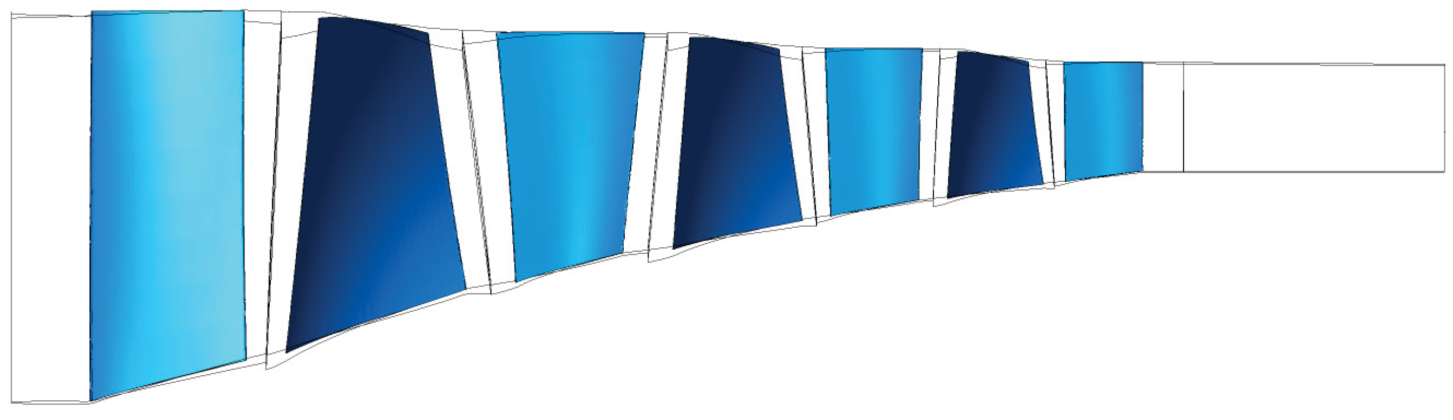
Figure 2.
Isometric view of compressor model with Casing Treatment and y+ ≤ 1.1.
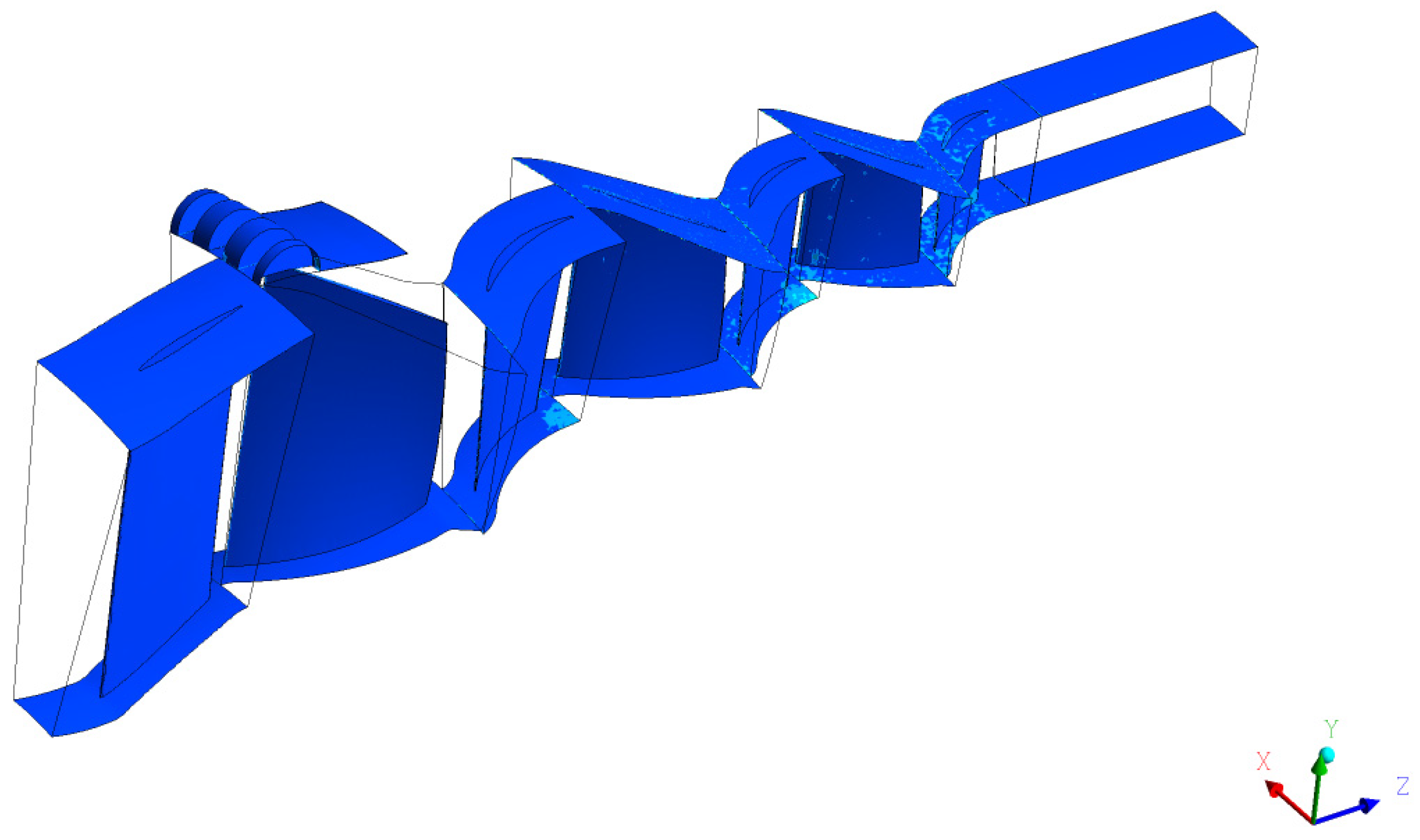
Figure 3.
Proposed Axial Slot casing treatment configuration. [24].
Figure 3.
Proposed Axial Slot casing treatment configuration. [24].
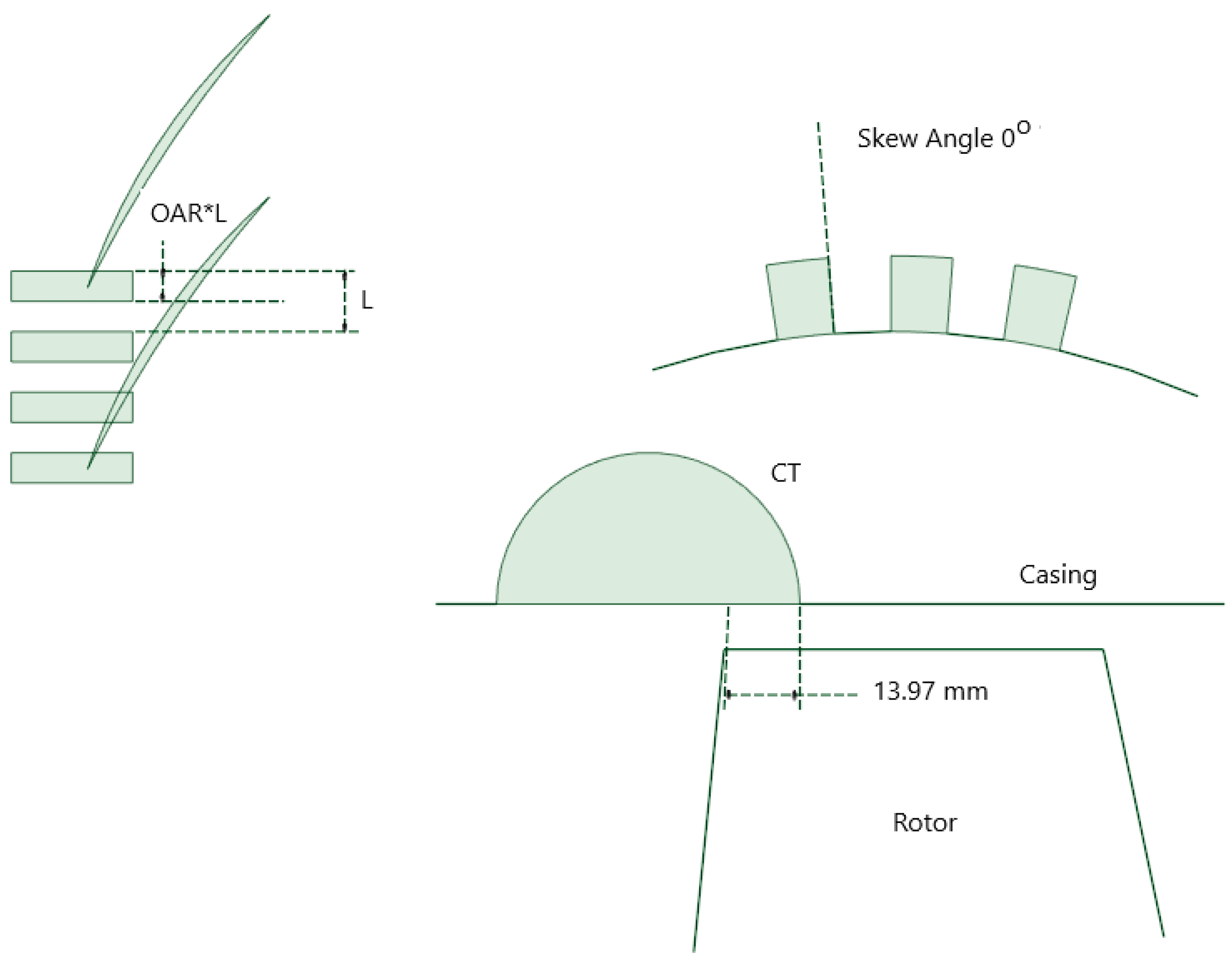
Figure 4.
RMS residuals of the RANS equations for the smooth wall case.
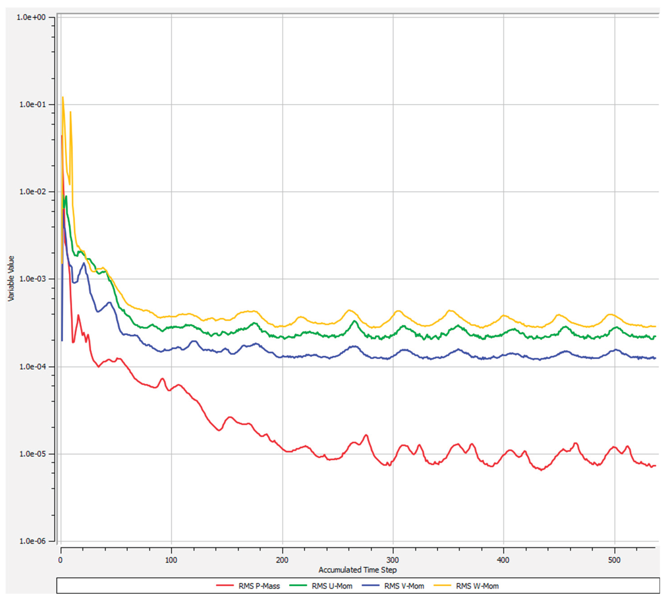
Figure 5.
10 relevant engine parameters monitored including mass imbalance between inlet and outlet in red color for numerical control.
Figure 5.
10 relevant engine parameters monitored including mass imbalance between inlet and outlet in red color for numerical control.
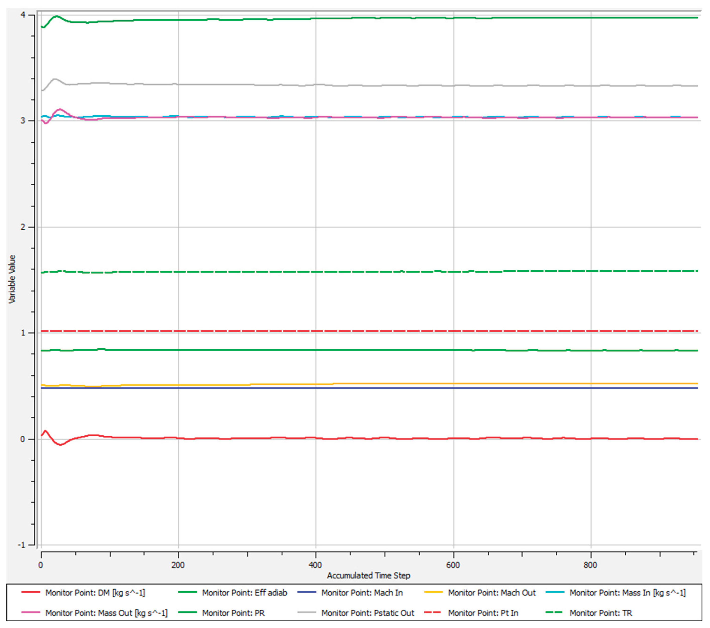
Figure 6.
Details of the mesh and prism layers inside the axial slots.
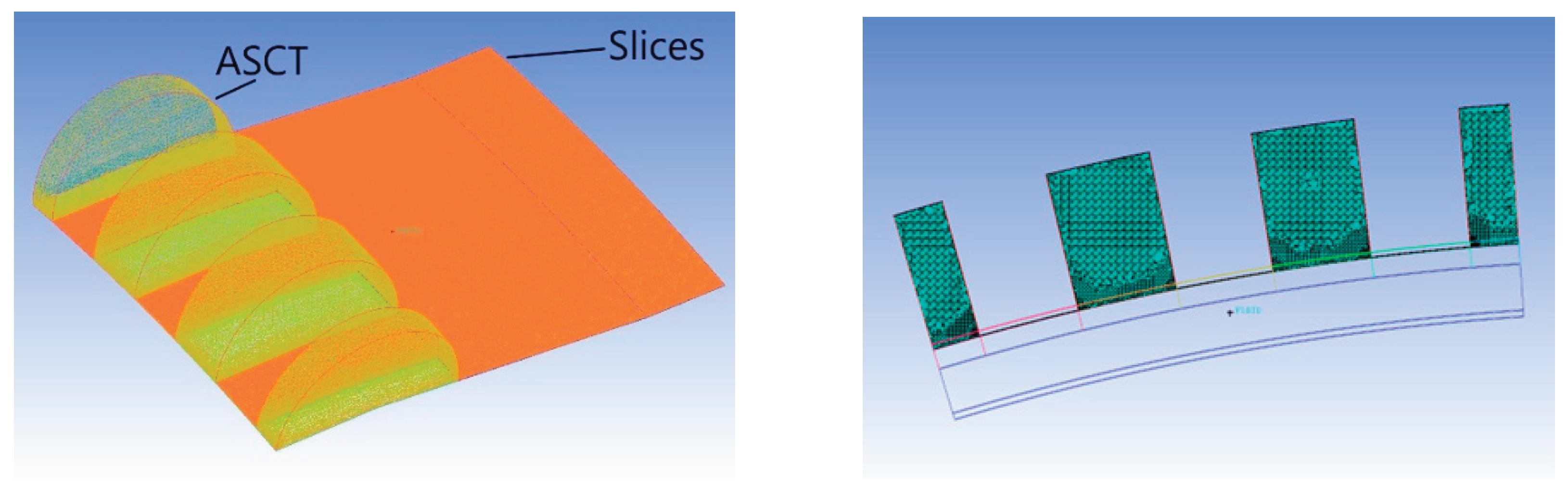
Figure 7.
Unstructured mesh of Rotor 1 blade with prism layers smooth wall and Rotor 1 with Axial Slots cases.
Figure 7.
Unstructured mesh of Rotor 1 blade with prism layers smooth wall and Rotor 1 with Axial Slots cases.
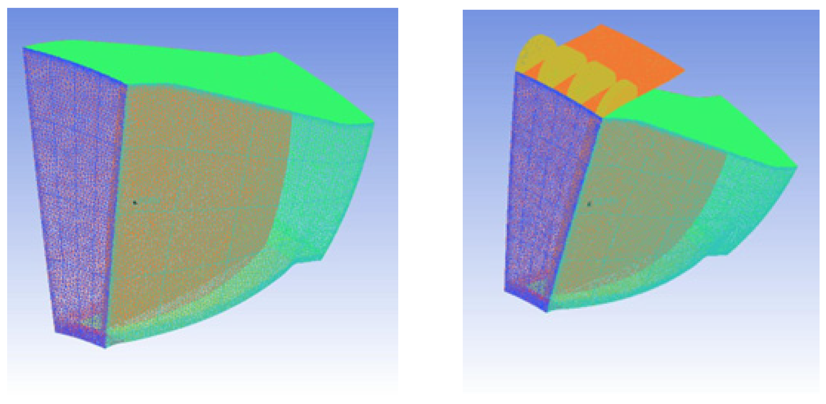
Figure 8.
Compressor map characteristics (relative pressure ratio) for N=100 % for the smooth wall.
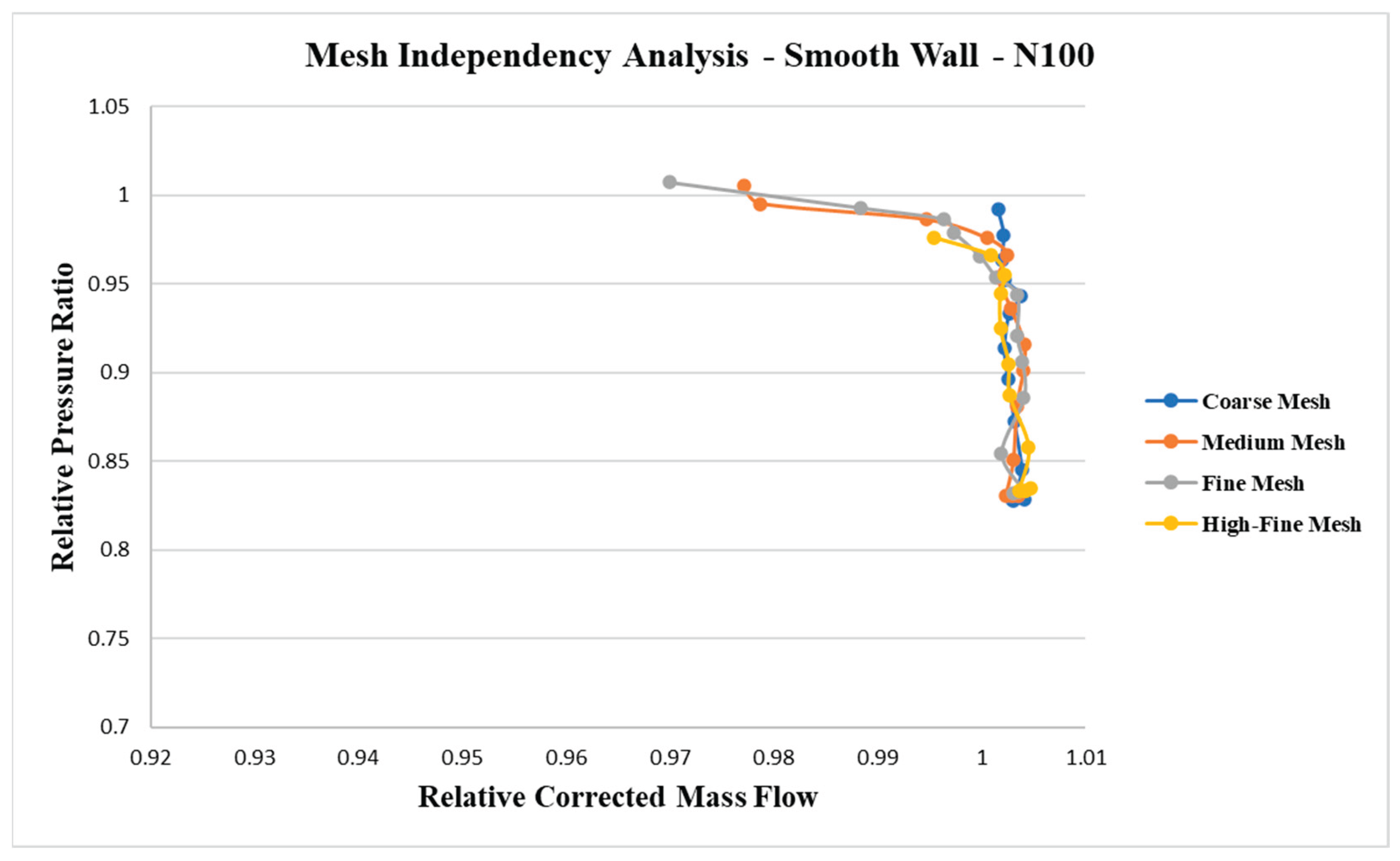
Figure 9.
Compressor map characteristics (relative pressure ratio) for N=100 % for the casing treatment with Axial Slots.
Figure 9.
Compressor map characteristics (relative pressure ratio) for N=100 % for the casing treatment with Axial Slots.
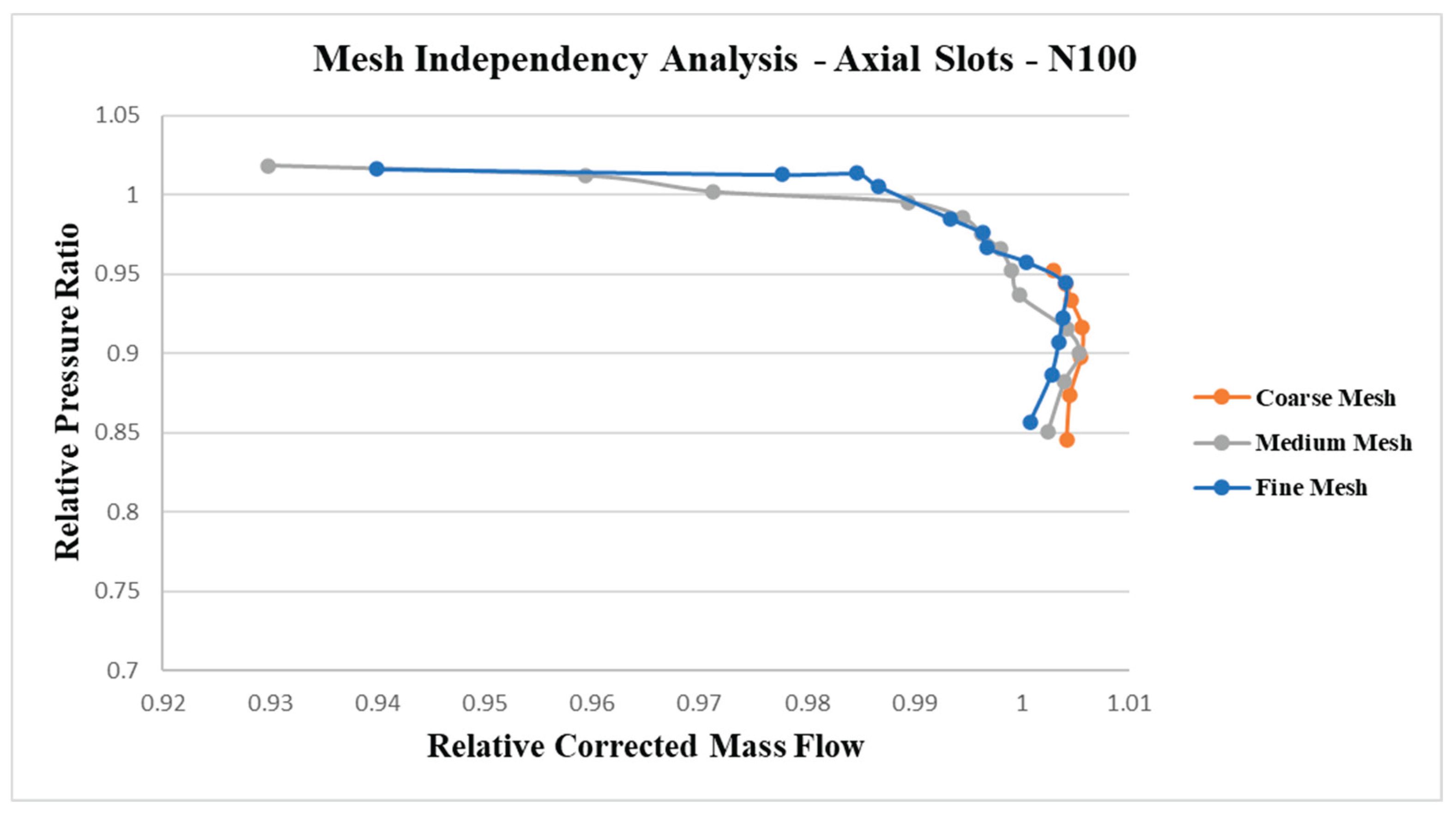
Figure 10.
Total pressure ratio vs Corrected mass flow – N100. Results from the present work (considering SC) compared with different references.
Figure 10.
Total pressure ratio vs Corrected mass flow – N100. Results from the present work (considering SC) compared with different references.
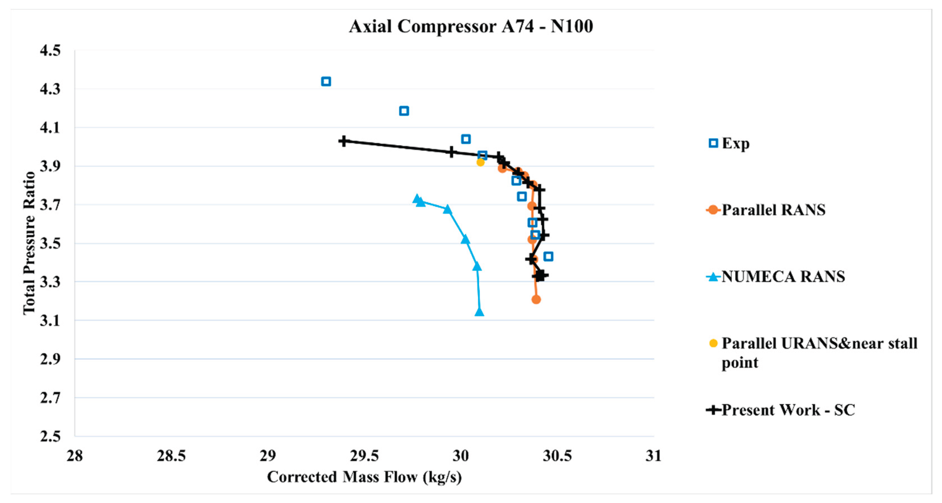
Figure 11.
Adiabatic efficiency vs Corrected mass flow – N100 - Results from the present work (considering SC) compared with different references.
Figure 11.
Adiabatic efficiency vs Corrected mass flow – N100 - Results from the present work (considering SC) compared with different references.
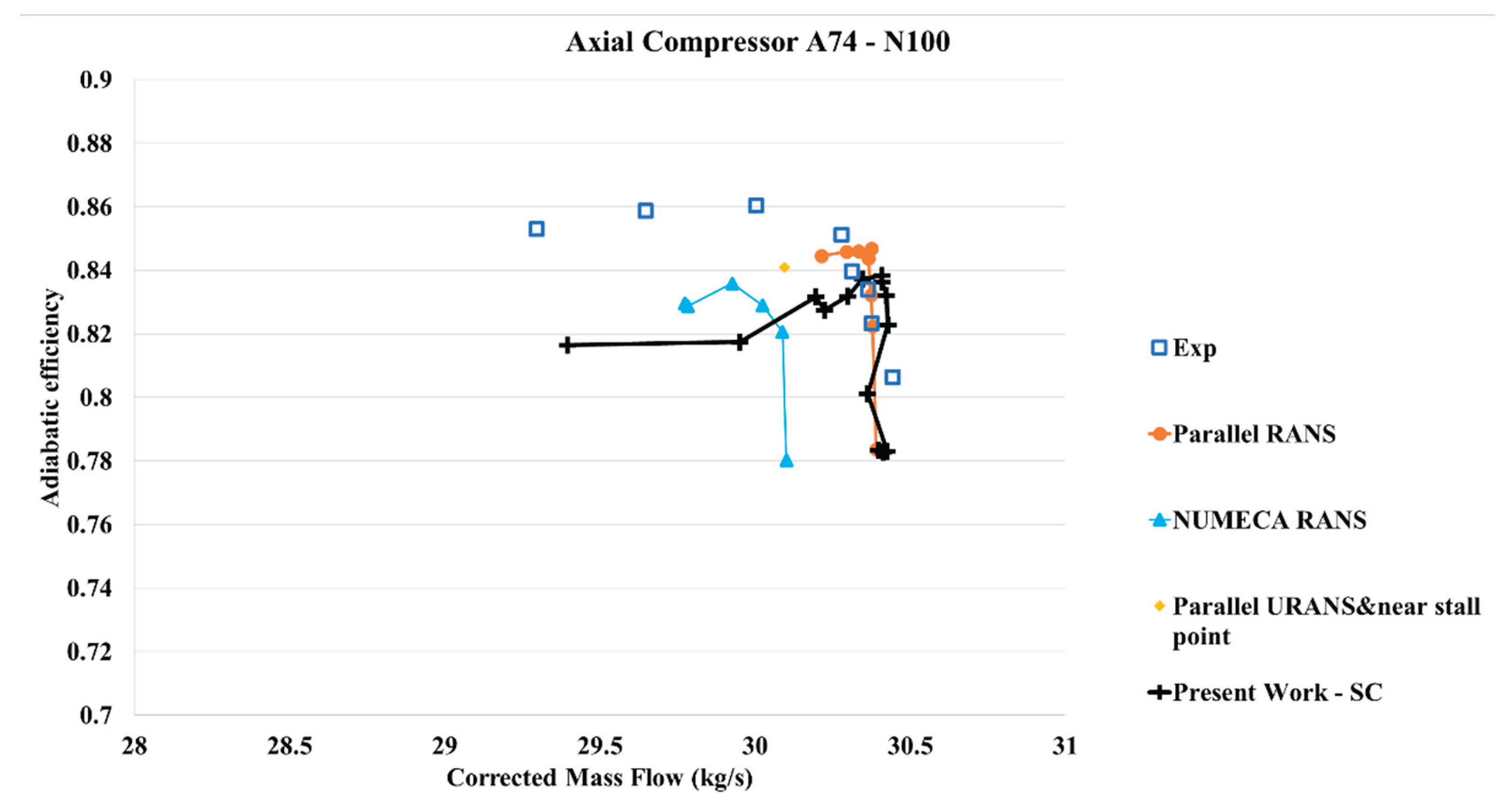
Figure 12.
Total pressure ratio vs Corrected mass flow – 100%N – Present work – CT compared to present work – SC, experimental data, and other CFD simulations.
Figure 12.
Total pressure ratio vs Corrected mass flow – 100%N – Present work – CT compared to present work – SC, experimental data, and other CFD simulations.
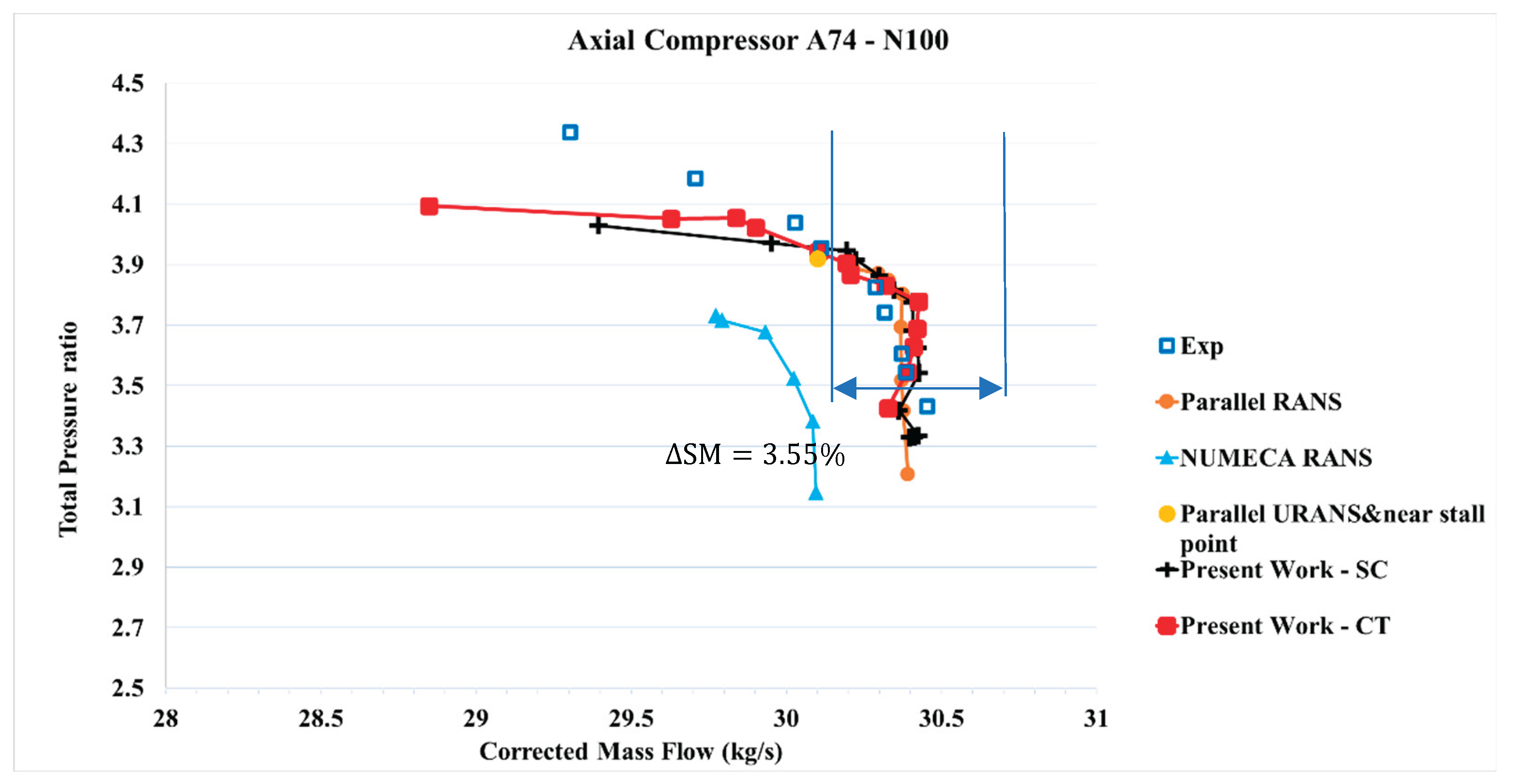
Figure 13.
Adiabatic efficiency vs Corrected mass flow – 100%N – Present work - CT compared to present work – SC, experimental data, and others CFD simulations.
Figure 13.
Adiabatic efficiency vs Corrected mass flow – 100%N – Present work - CT compared to present work – SC, experimental data, and others CFD simulations.
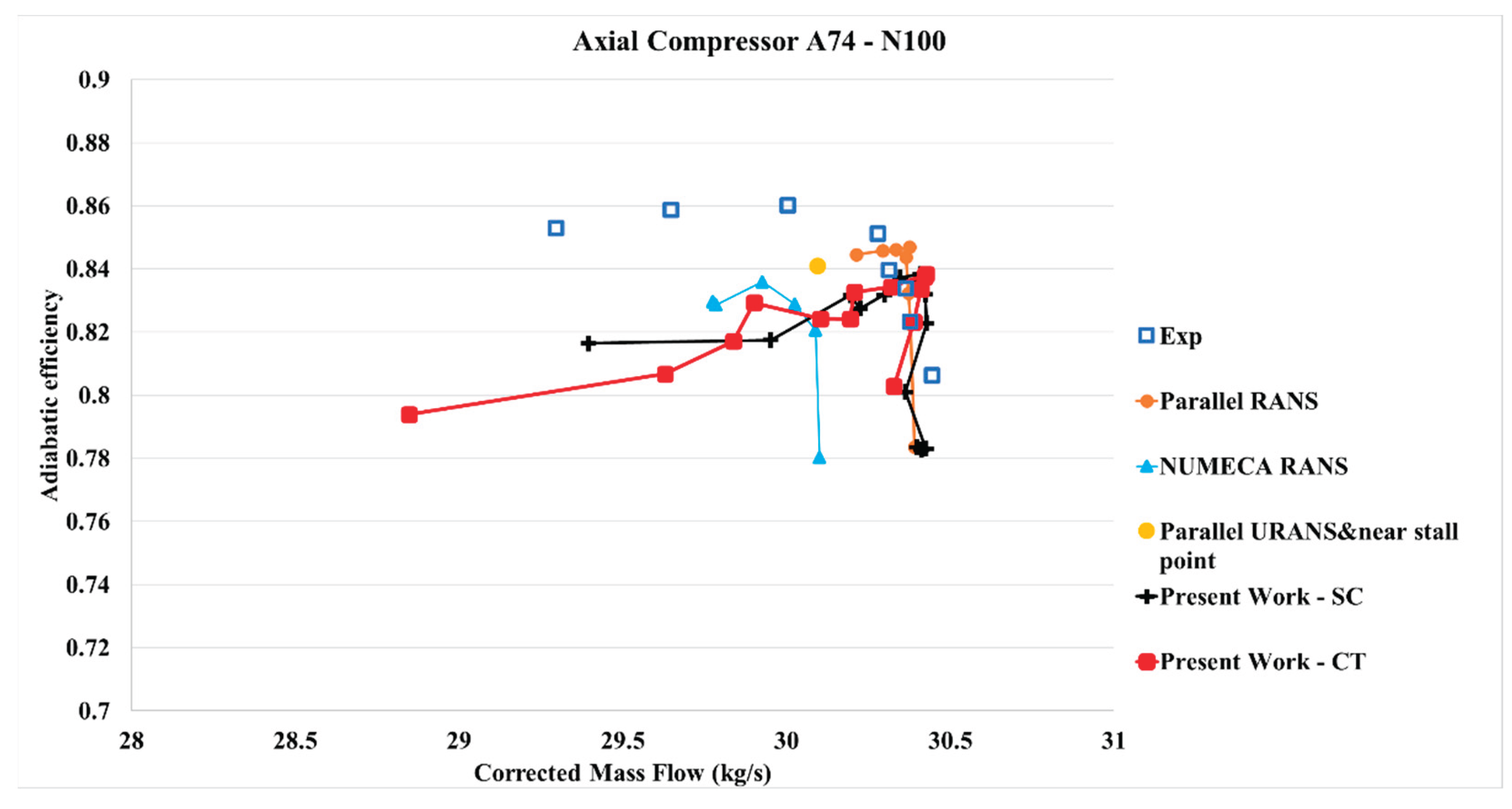
Figure 14.
Total Pressure ratio vs Corrected mass flow – 95%N – Results from the present work (considering SC and CT) compared with different references.
Figure 14.
Total Pressure ratio vs Corrected mass flow – 95%N – Results from the present work (considering SC and CT) compared with different references.
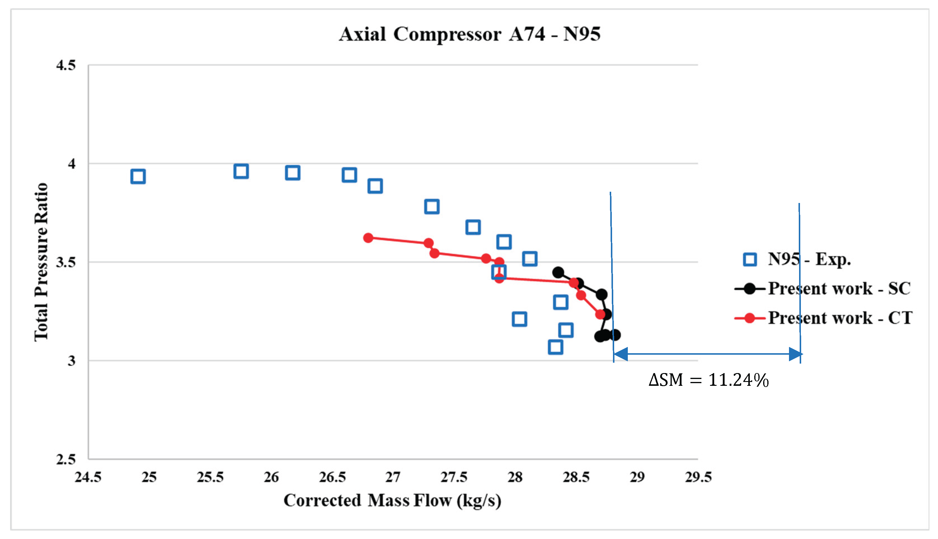
Figure 15.
Adiabatic efficiency vs Corrected mass flow – 95%N – Results from the present work (considering SC and CT) compared with different references.
Figure 15.
Adiabatic efficiency vs Corrected mass flow – 95%N – Results from the present work (considering SC and CT) compared with different references.
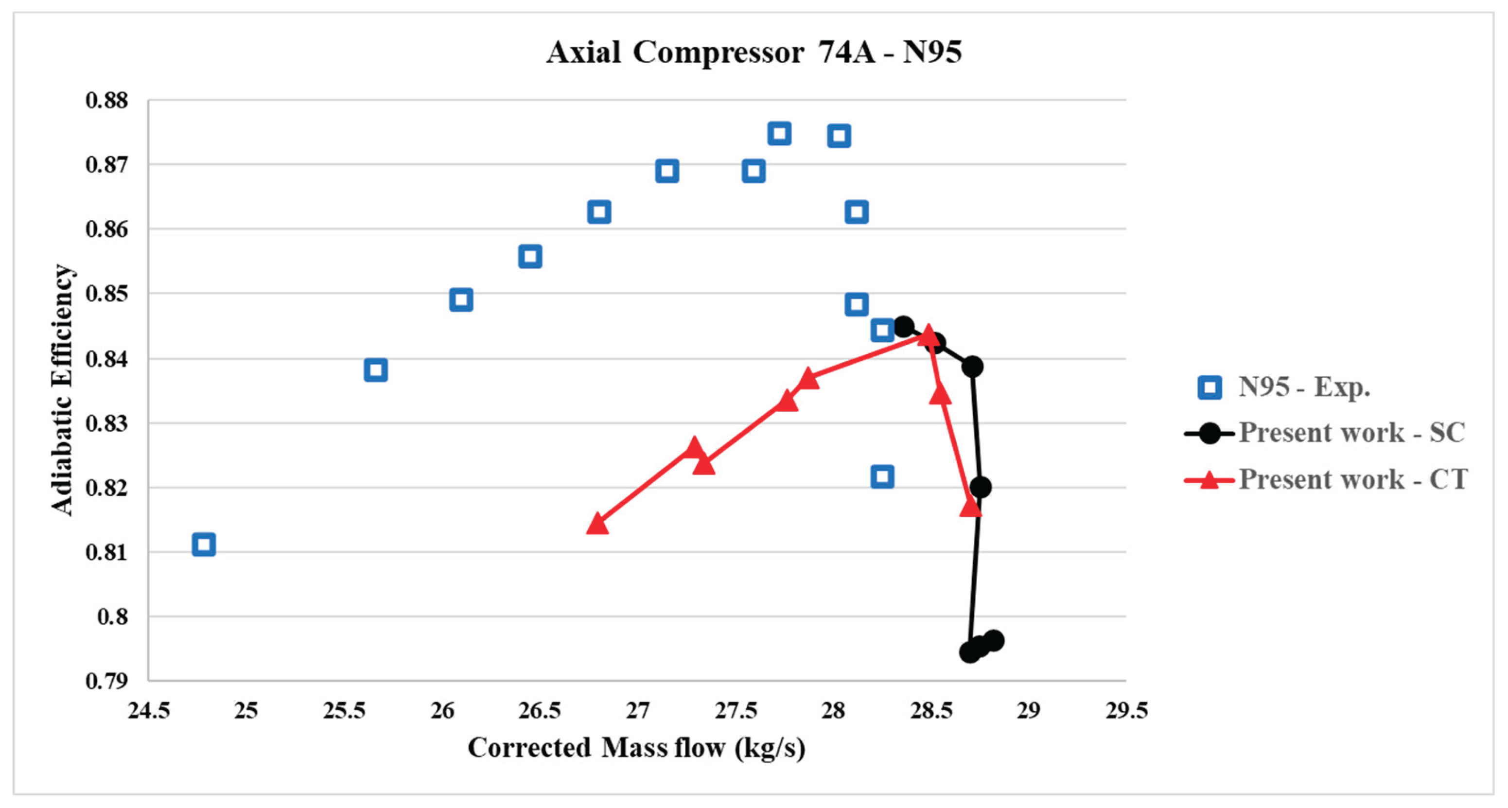
Figure 16.
Total Pressure vs Corrected mass flow – 85%N – Results from the present work (considering SC and CT) compared with different references.
Figure 16.
Total Pressure vs Corrected mass flow – 85%N – Results from the present work (considering SC and CT) compared with different references.
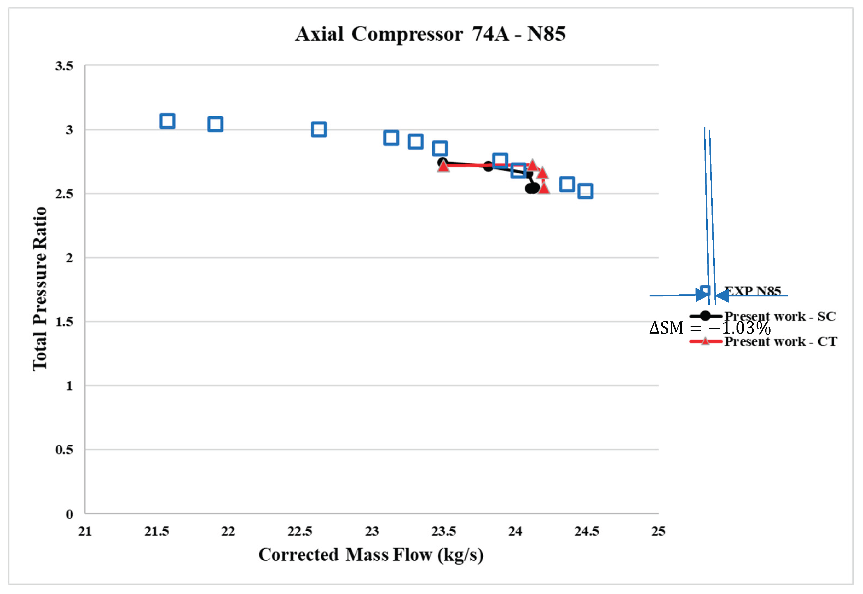
Figure 17.
Adiabatic efficiency vs Corrected mass flow – 85%N – Results from the present work (considering SC and CT) compared with different references.
Figure 17.
Adiabatic efficiency vs Corrected mass flow – 85%N – Results from the present work (considering SC and CT) compared with different references.
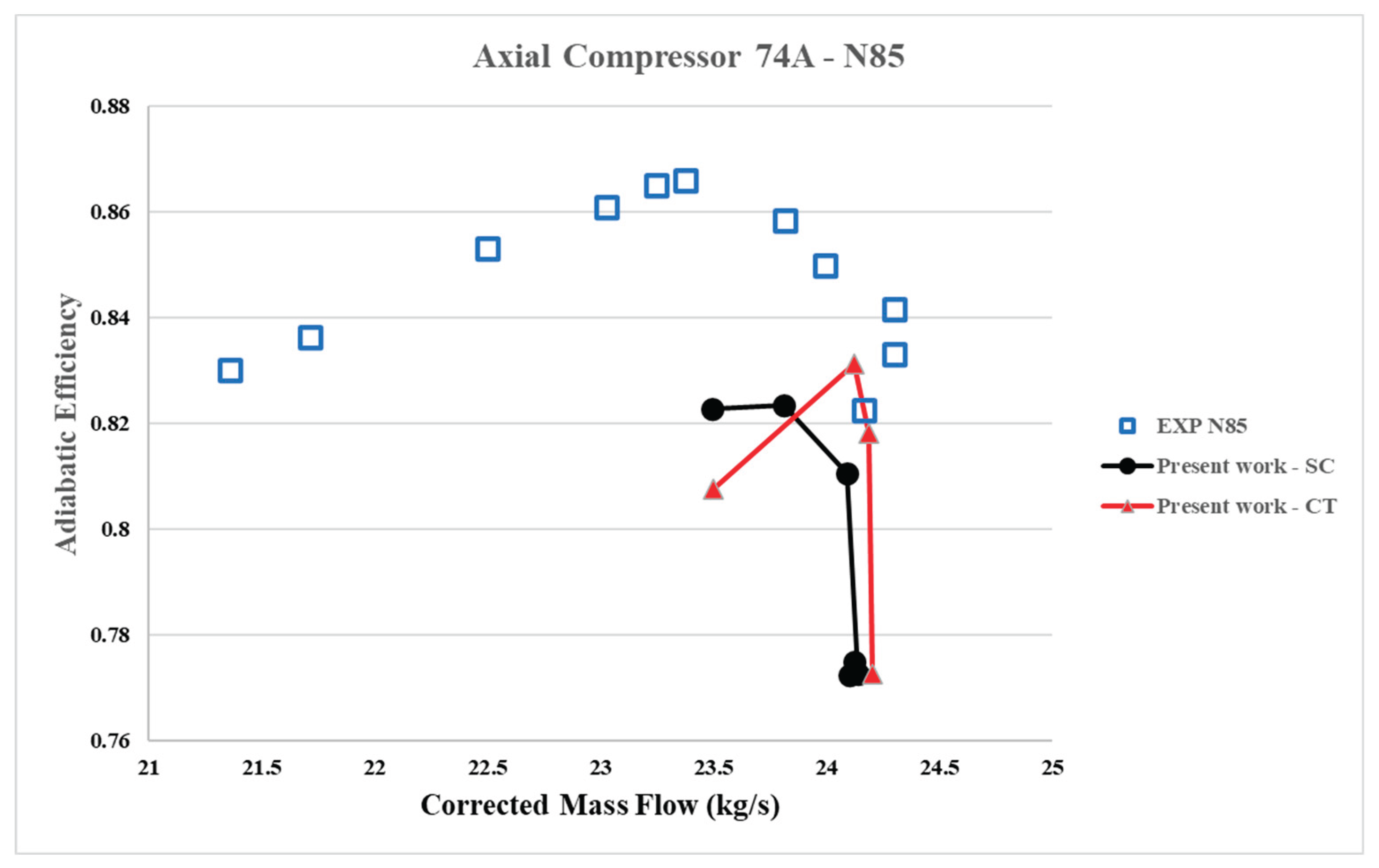
Figure 18.
Pressure distribution for smooth casing in the meridional view for N=0.95.
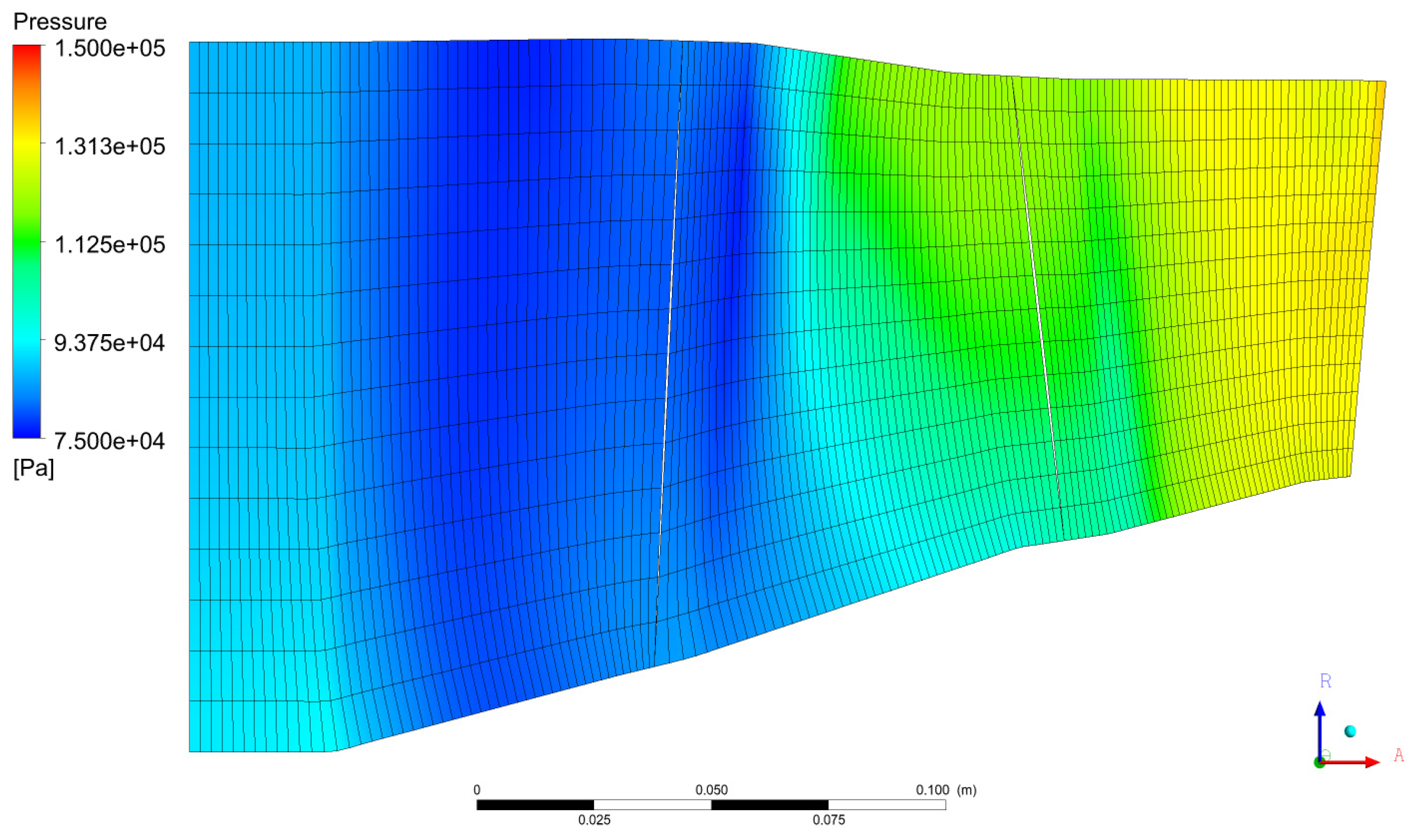
Figure 19.
Pressure distribution with CT in the meridional view for N=0.95.
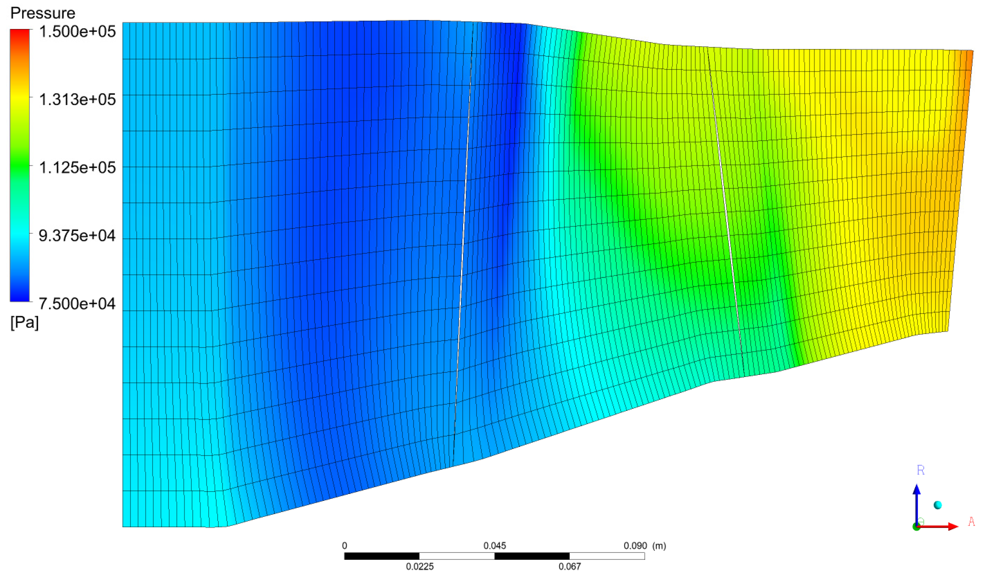
Figure 20.
Mach number contours for 95%N for the smooth casing at 95% of blade span.
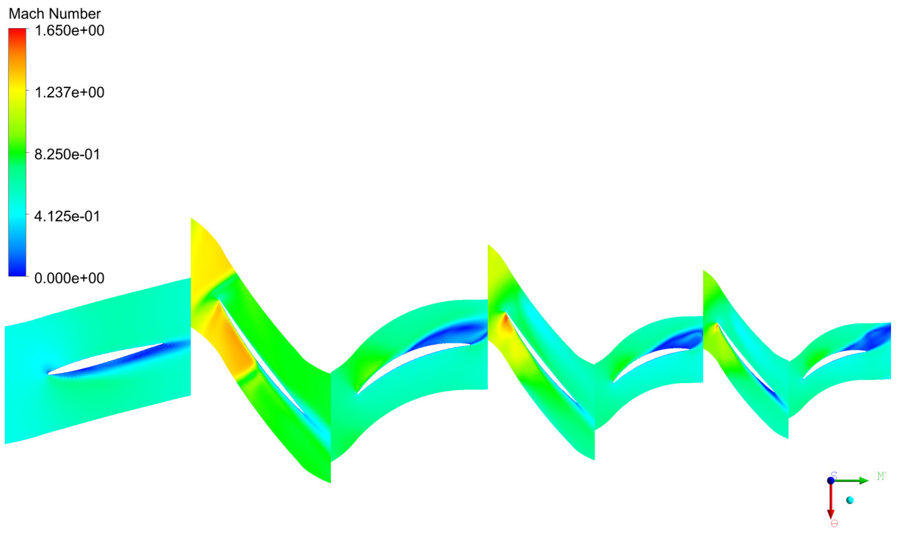
Figure 21.
Mach number contours for 95%N with casing treatment in the Rotor 1 at 95% of blade span.
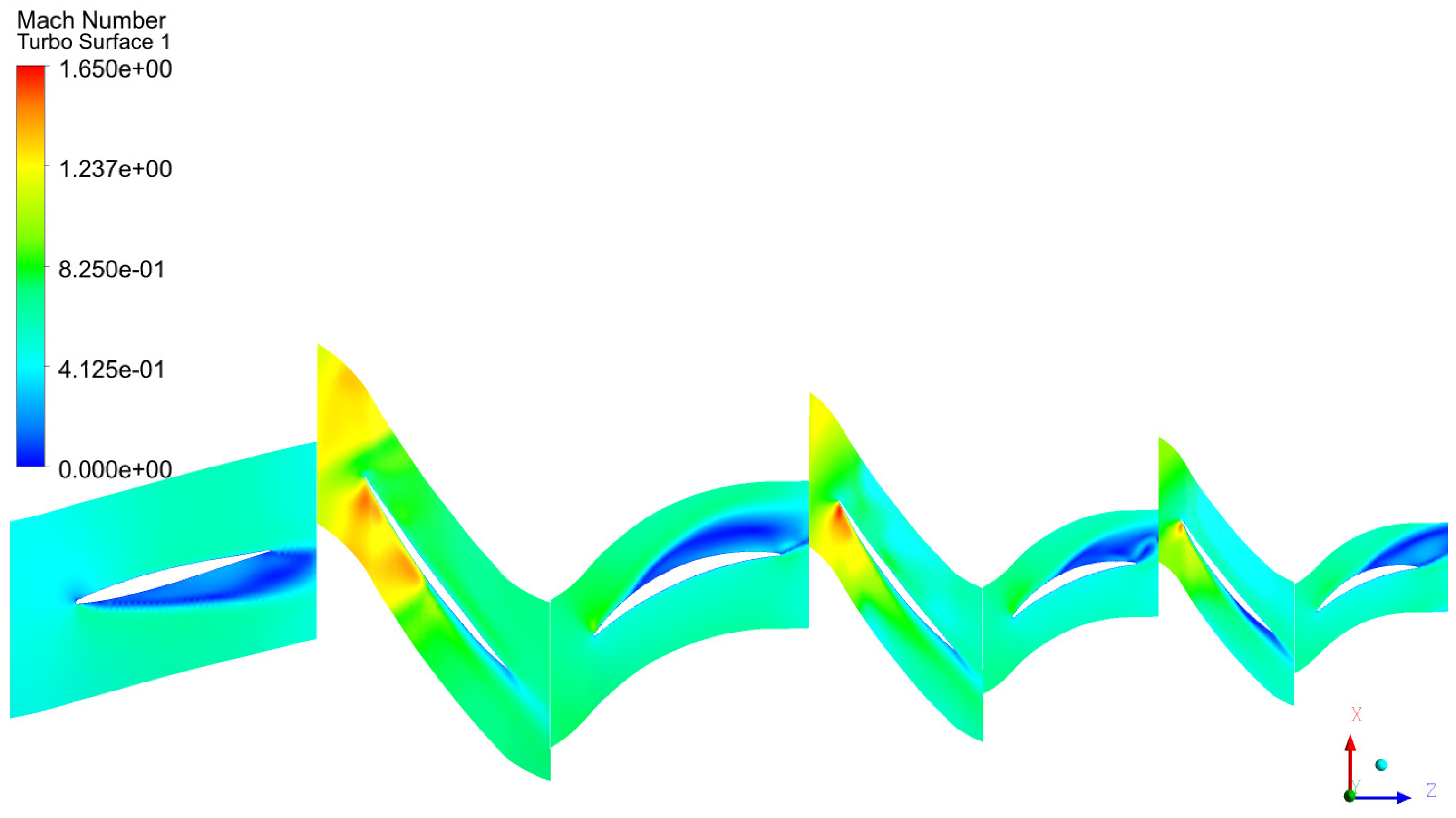
Figure 22.
Mach number contours for 95%N for the smooth casing at 30% of blade span from hub.
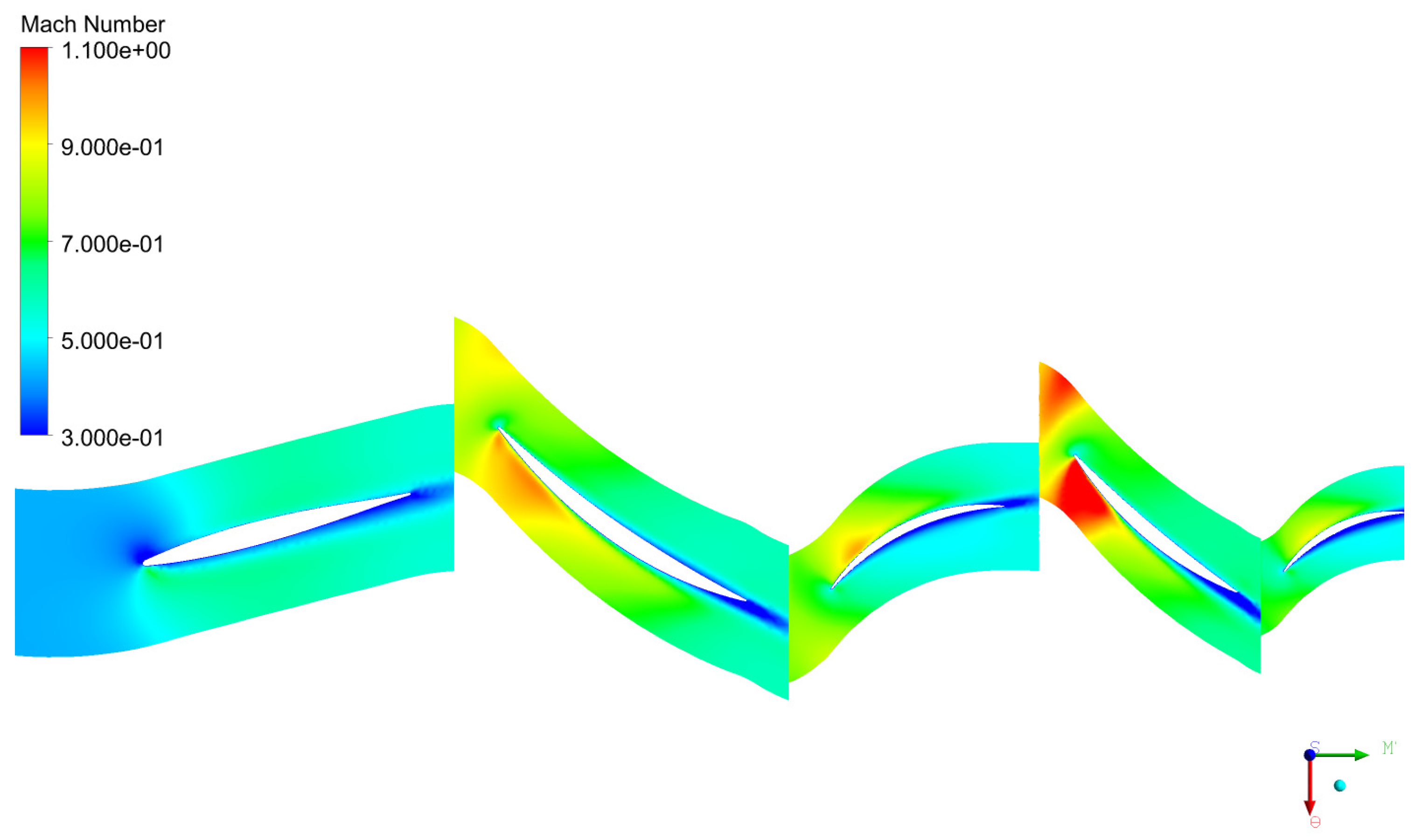
Figure 23.
Mach number contours for 95%N with casing treatment in the Rotor 1 at 30% of blade span from hub.
Figure 23.
Mach number contours for 95%N with casing treatment in the Rotor 1 at 30% of blade span from hub.
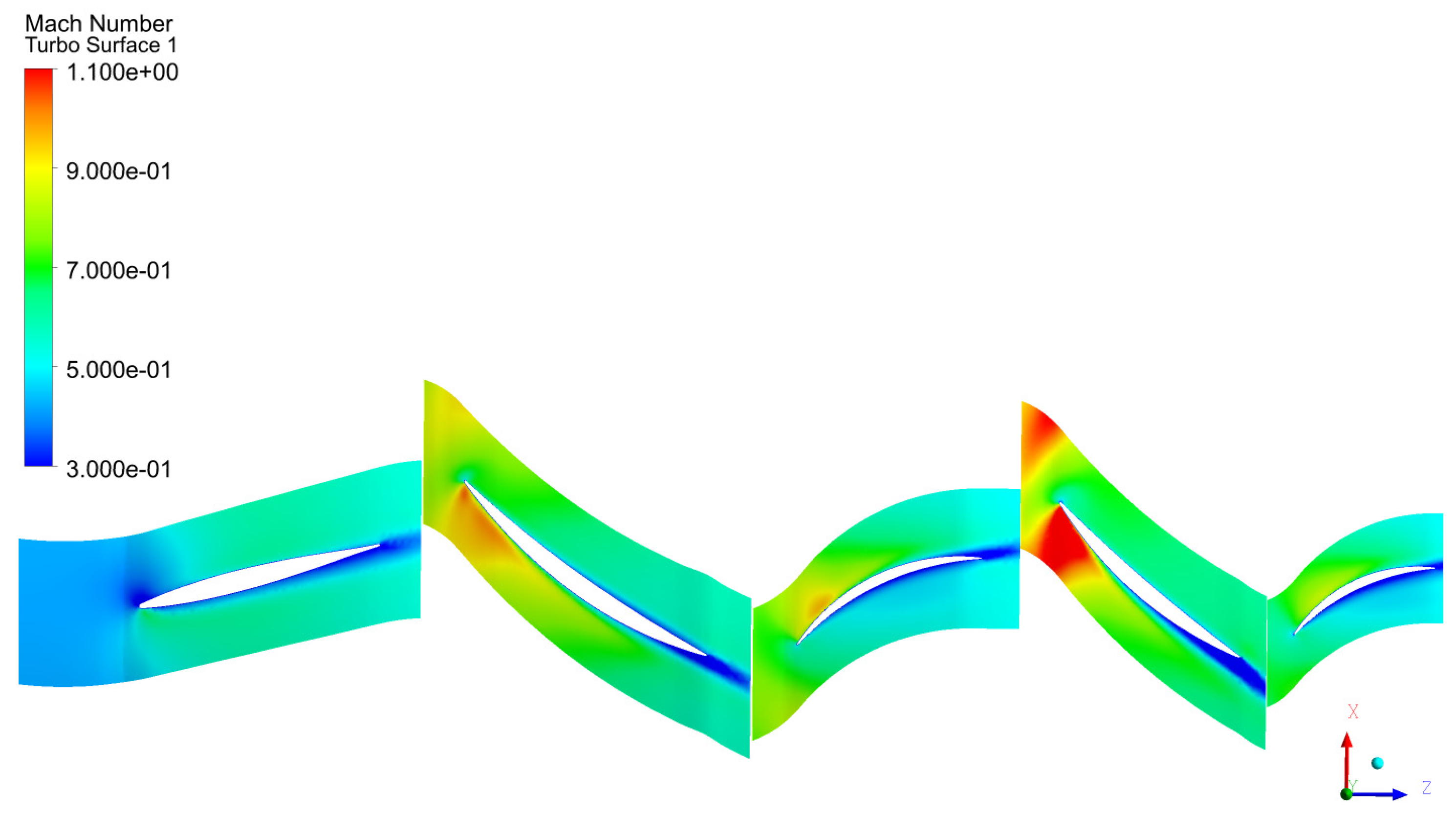
Figure 24.
Relative total pressure contours for 95%N in blade-to-blade planes at near-stall condition smooth wall.
Figure 24.
Relative total pressure contours for 95%N in blade-to-blade planes at near-stall condition smooth wall.
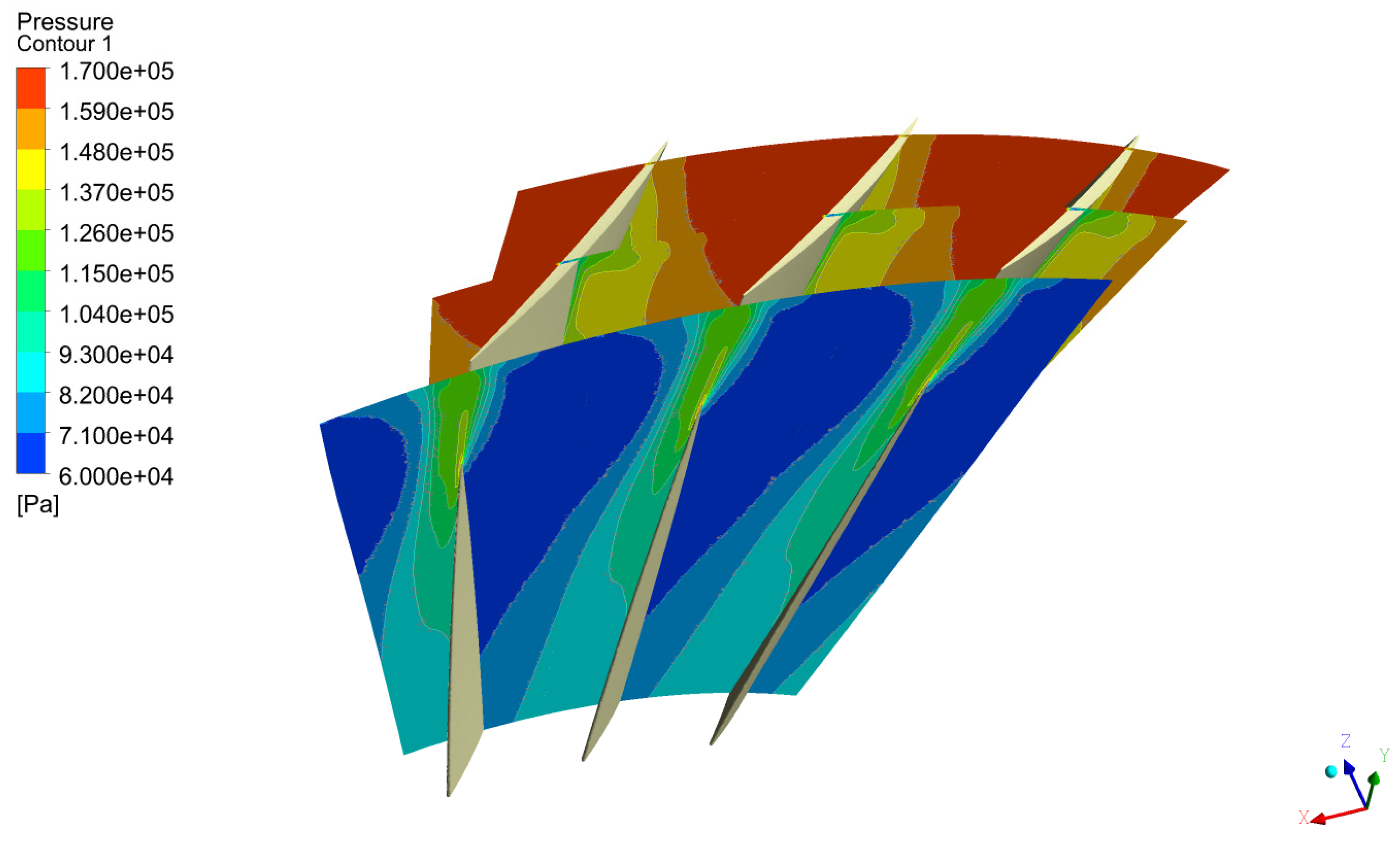
Figure 25.
Relative total pressure contours for 95%N in blade-to-blade planes at near-stall condition axial slots.
Figure 25.
Relative total pressure contours for 95%N in blade-to-blade planes at near-stall condition axial slots.
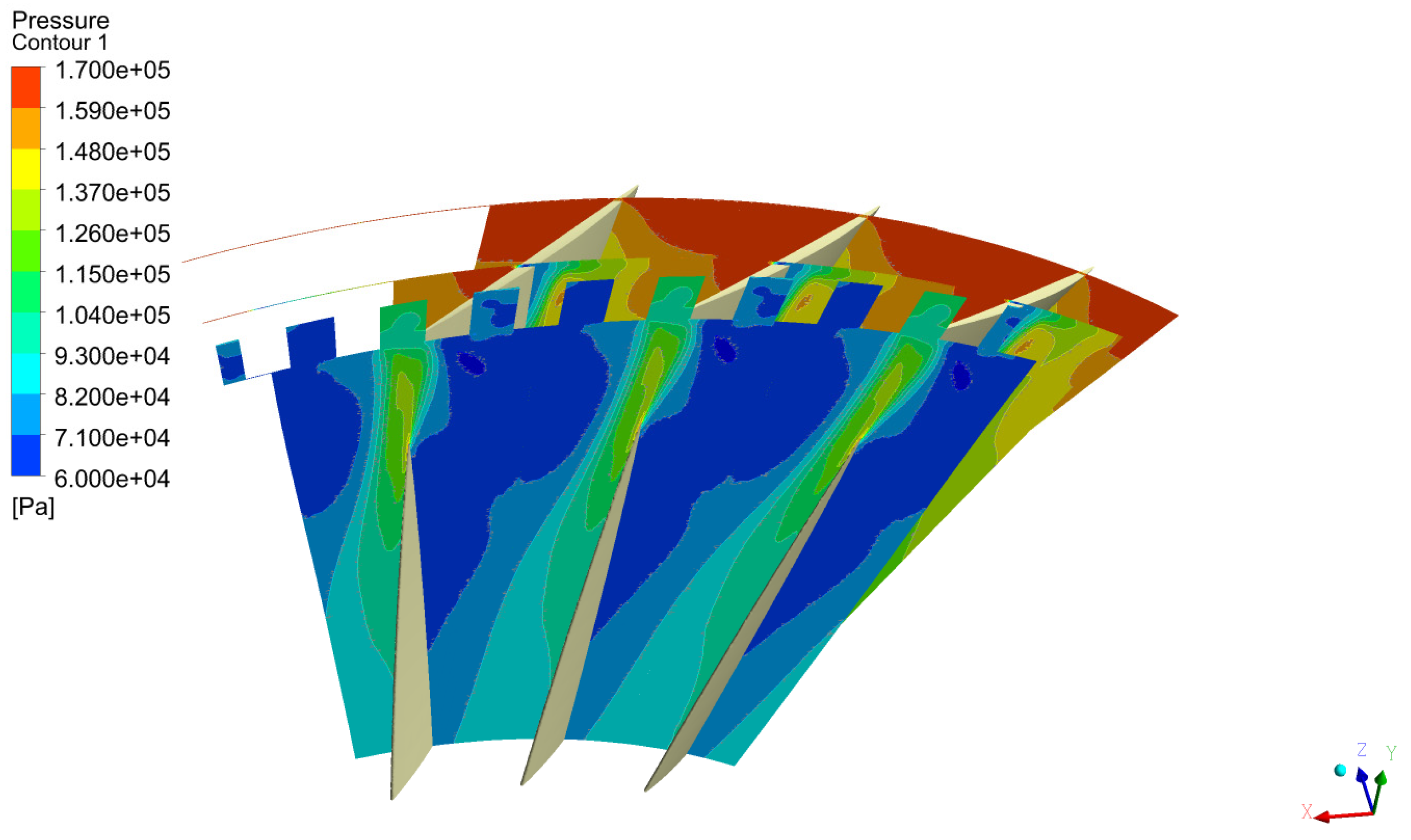
Figure 26.
Streamlines starting from a plane inside one axial slot for 95%N at outlet static pressure of 295 kPa (near stall).
Figure 26.
Streamlines starting from a plane inside one axial slot for 95%N at outlet static pressure of 295 kPa (near stall).
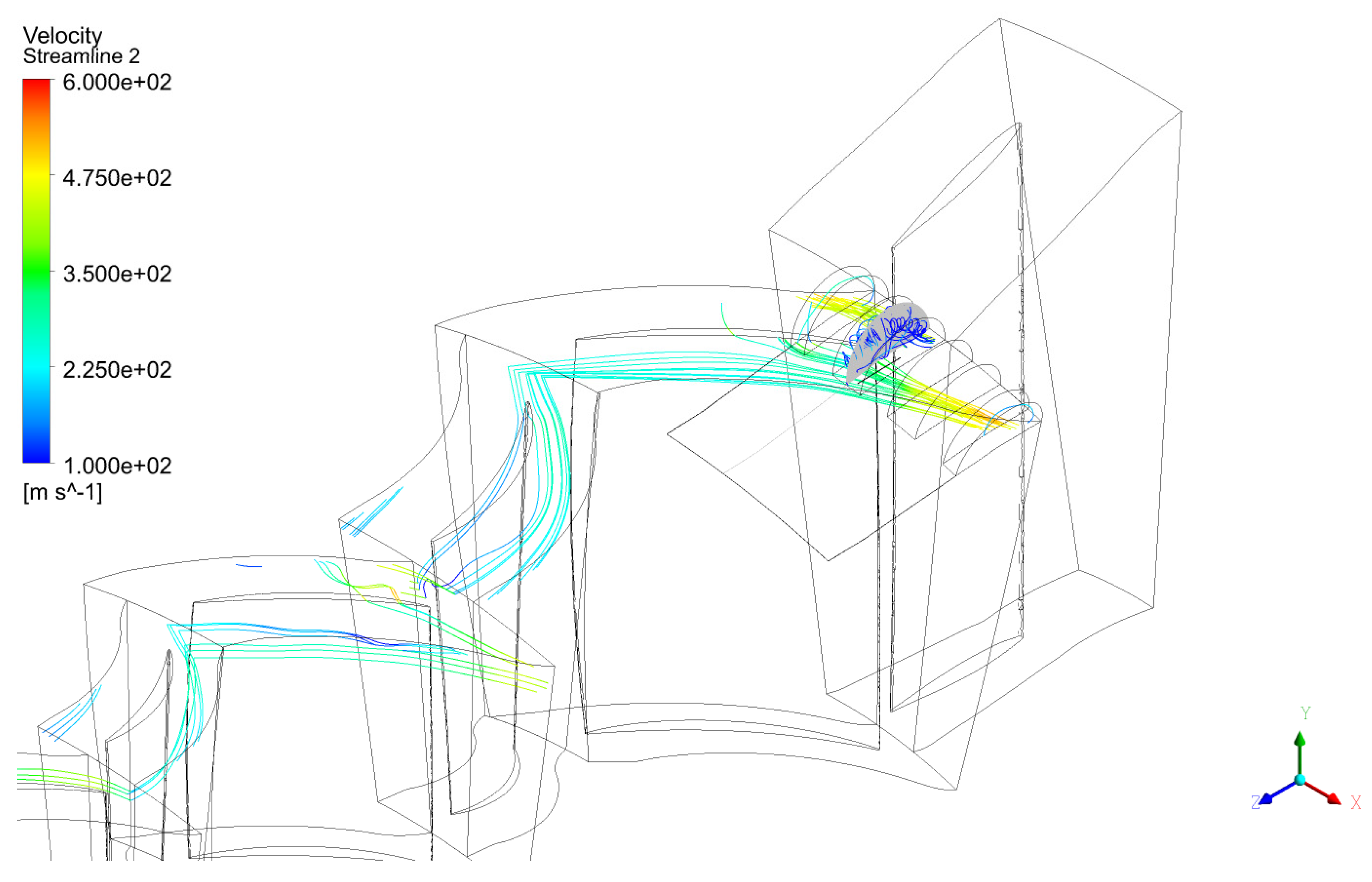
Figure 27.
Streamlines starting from a line inside one axial slot for 95%N at outlet static pressure of 295 kPa (near stall).
Figure 27.
Streamlines starting from a line inside one axial slot for 95%N at outlet static pressure of 295 kPa (near stall).
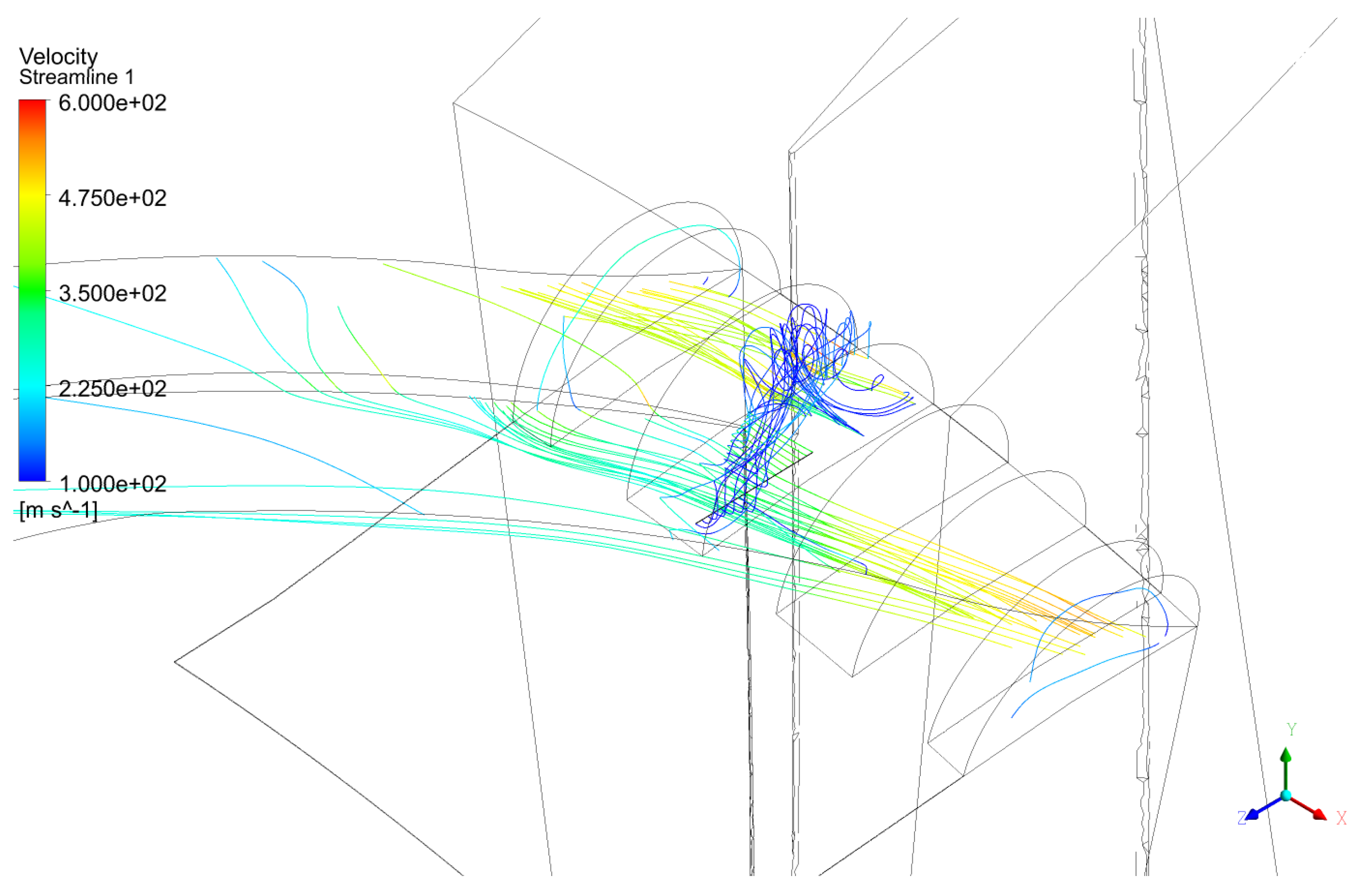

Table 1.
Geometrical parameters for 3.5 stages axial compressor from Steinke [21].
Table 1.
Geometrical parameters for 3.5 stages axial compressor from Steinke [21].
| Design Parameters | Value |
| Number of the IGV Blade | 26 |
| Blade Count R1 | 28 |
| Blade Count S1 | 34 |
| Blade Count R2 | 32 |
| Blade Count S2 | 46 |
| Blade Count R3 | 39 |
| Blade Count S3 | 54 |
| Estimated Efficiency | 79.9 % |
| Tip diameter of Rotor 1 | 0.505 m |
| Rotor 1 hub to tip ratio | 0.54 |
| Rotor 1 tip gap (% of span) | < 1.0 % |
Table 2.
Main parameters of axial compressor with smooth wall grid refinement study.
| Number of elements (Millions) | Number of prism layers | Initial height (m) | y+ | |
| Mesh 1(coarse) | 8.2 | 27 | 1e-7 | < 1.1 |
| Mesh 2(medium) | 14.3 | 27 | 1e-7 | < 1.1 |
| Mesh 3(fine) | 25.2 | 27 | 1e-7 | < 1.1 |
| Mesh 4(high fine) | 33.9 | 27 | 1e-7 | <1.1 |
Table 3.
Smooth wall axial compressor calculations of discretization error for meshes 2, 3 and 4.
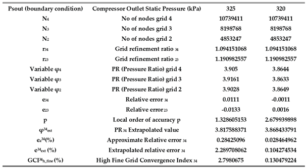 |
Table 4.
Main parameters of axial compressor with casing treatment grid refinement study.
| Number of elements (Millions) | Number of prism layers | Initial height (m) | y+ | |
| Mesh 5(coarse) | 10.4 | 27 | 1e-7 | < 1.1 |
| Mesh 6(medium) | 17.9 | 27 | 1e-7 | < 1.1 |
| Mesh 7(fine) | 31.3 | 27 | 1e-7 | < 1.1 |
Table 5.
Axial Slots calculations of discretization error for meshes 5, 6 and 7.
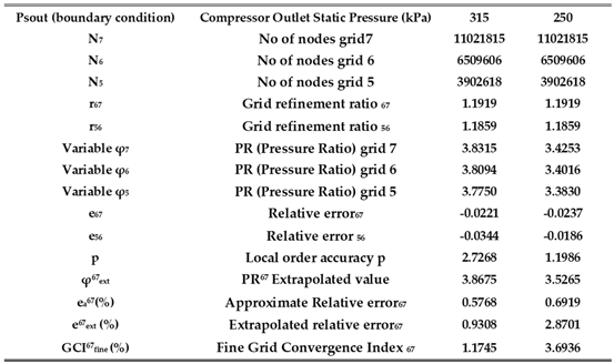 |
Table 6.
Variation of , PR, ηis, peak and SM with axial slots at different speeds.
| N (%) | PR | ηisen, peak | ΔSM | |
|---|---|---|---|---|
| 100 | -1.86% | +1.62% | -0.01% | +3.55% |
| 95 | -5.49% | +2.05% | +0.67% | +11.24% |
| 85 | +0.00% | -0.70% | +0.79% | -1.03% |
Disclaimer/Publisher’s Note: The statements, opinions and data contained in all publications are solely those of the individual author(s) and contributor(s) and not of MDPI and/or the editor(s). MDPI and/or the editor(s) disclaim responsibility for any injury to people or property resulting from any ideas, methods, instructions or products referred to in the content. |
© 2025 by the authors. Licensee MDPI, Basel, Switzerland. This article is an open access article distributed under the terms and conditions of the Creative Commons Attribution (CC BY) license (http://creativecommons.org/licenses/by/4.0/).
Copyright: This open access article is published under a Creative Commons CC BY 4.0 license, which permit the free download, distribution, and reuse, provided that the author and preprint are cited in any reuse.


