
Submitted:
09 July 2025
Posted:
10 July 2025
You are already at the latest version
Abstract
The recycling of nickel-cadmium batteries poses a significant environmental challenge due to cadmium’s high biotoxicity. This study proposes a green method for recovering cadmium from cadmium oxide (CdO) using carbon (coal) in the presence of a molten binary flux (KCl:NaCl = 0.507:0.493, melting point 667°C). The flux's relatively low density and conductivity enable cadmium reduction beneath and through the flux layer, resembling conditions in a fluidised bed reactor. Coarse coal (5–25 mm) served as the reductant. To enhance the process, electrovortex flows (EVF) were employed—generated by the interaction between non-uniform AC electric currents and their self-induced magnetic fields. The graphite crucible acted as both one of the electrodes, with a graphite rod as the second electrode. As Cd and CdO are denser than both the flux and coal, the reduction proceeded below the flux layer. The flux facilitated CdO transport to the reductant, speeding up the reaction. X-ray diffraction (XRD) and scanning electron microscopy (SEM) confirmed the formation of metallic cadmium beneath and within the flux layer. This method demonstrates the feasibility of flux-assisted cadmium recovery without prior mixing and offers a foundation for further optimisation of sustainable battery recycling.
Keywords:
green technology
; cadmium waste recycling
; cadmium oxide
; cadmium reduction
; protective fluxes
; electromagnetic stirring (MHD pump)
; electrovortex flows
1. Introduction
Alkaline nickel-cadmium (Ni-Cd) batteries are commonly used as autonomous sources of industrial and domestic electric power due to their favourable combination of technical, economic, and electrical properties. [1]
This paper explores the technical aspects of a future cadmium battery recycling technology. A comprehensive review of the cadmium battery market and existing recycling technologies is available in previous publications [2].
Current environmental and economic demands for battery disposal and recycling have also been discussed previously [3].
However, there is still no environmentally friendly and economically viable technology for processing spent batteries to produce quality materials. Thus, ongoing research in this area remains highly relevant.
The cumulative charge/discharge reactions in Ni-Cd batteries are described by the following equation (1) [4]:
For Cd recovery from Cd(OH)2, the proposed method uses thermal decomposition at 400°C. A monoclinic γ-Cd(OH)2 phase and a cubic CdO phase form at 300°C. A pure cubic CdO phase is obtained at 400°C. At 700°C, both CdO and CdO2 phases appear [5] Since cadmium evaporation becomes significant above 765°C, the reduction process is limited to 700°C to avoid CdO2 formation and reduce Cd loss [6].
Cd(OH) 2 → CdO + Н2О
The overall reduction reaction was ensured by the reduction of Cd according to Volynsky et al. [7] by a cumulative reaction from 650–1100 ◦C (3):
2CdO + C → 2Cd + CO2
Further reduction can also proceed through intermediate reactions (4) and (5):
CdO + C → Cd + CO
CdO + CO → Cd + CO2
In this study, an excess molar ratio of CdO:C = 1:50, which significantly exceeds the minimum ratio of 1:0.5 required for reaction (3) to proceed, was used to ensure complete reduction via reaction (4) and partial conversion through reaction (5). The surplus carbon prevents the reoxidation of the produced Cd on the slag surface.
Carbon-based reductants such as anthracite [8] and carbon black [7] have been investigated in pyrometallurgical processes for Cd recovery.
Slags are proposed in Ni-MH battery recycling for extracting rare earth oxides [9,10]. In this case, as a result of high-temperature treatment, a Ni-Co alloy and a heterooxide material are obtained. In these processes, slag systems of the CaO-CaF2, CaO-SiO2-MgO and SiO2-Al2O3 types are used.
Electroslag remelting (ESR) is a secondary refining process where a consumable electrode is remelted under a protective slag. Slag functions include heating (via Joule heating), dissolving non-metallic inclusions, refining the metal, and shielding it from the atmosphere [11,12]. The metallothermic reduction of TiCl4 by liquid Mg in an ESR setup using a non-consumable electrode was demonstrated by Platacis et al.[6].
To reduce energy and reagent consumption and to minimize or eliminate Cd evaporation, a sustainable production approach must be implemented.
Sustainable practices aim to reduce energy and reagent consumption and minimise Cd evaporation. The goal of this study is to avoid Cd loss from the reaction volume during high-temperature reduction. This method enables Cd pre-separation from spent batteries without heating the entire mass excessively. Cd has a melting point of 321°C and a boiling point of 765°C [6]. Reduction is carried out using crushed coal (5–25 mm) within molten chloride salts at temperatures below Cd’s boiling point and without inert gas protection. The flux is critical for implementing the electroslag process effectively.
The study qualitatively evaluates the influence of salt flux on the efficiency of CdO reduction in and beneath the flux layer, and during CdO transport. An alternating current heats the chloride flux mixture in a graphite crucible using a graphite electrode. Electrovortex flows stir the molten flux, CdO, and reduced Cd, enhancing interaction with the static crushed carbon bed.
2. Materials and Methods
To prevent Cd evaporation, a binary KCl-NaCl flux was chosen with a molar ratio of 0.507:0.493, corresponding to the eutectic point with the lowest melting temperature (667˚C) [4], as shown in the liquidus projection diagram of the binary KCl-NaCl (KN) shown in Figure 1. This approach prevents the evaporation of the formed Cd, which occurs at temperatures above 765˚C [6].
To create the slag coating, chemically pure (>99.0%) mixtures of reagents KCl (Firma CHEMPUR, Poland) and NaCl (Sigma-Aldrich, Merck KGaA, Germany) were used.
The weight of all components was measured on a laboratory balance (KERN 440-35A, accuracy 0.01 g) and then ground using a kitchen mill (Clatronic KM 3350 Kitchen Machine, Clatronic International GmbH, Kempen Germany) equipped with a plastic vessel for 3 min. The total weight of the mixture added to the mill was 100 g for each grinding process.
The alternating current through the molten flux interacts with the alternating magnetic field, creating electromagnetic forces inside the melt. These forces have a constant and pulsating component. The constant component of the electromagnetic force is highly non-uniform due to the geometry of the device, which leads to rotation of the melt.
Figure 3.
Structure of theElectrovortex Flows. 1) small electrode – graphite, 2) liquid flux, 3) large electrode – graphite crucible. I – current strength, J – electric current density, B – self-magnetic field, U – liquid flux velocity. [22].
Figure 3.
Structure of theElectrovortex Flows. 1) small electrode – graphite, 2) liquid flux, 3) large electrode – graphite crucible. I – current strength, J – electric current density, B – self-magnetic field, U – liquid flux velocity. [22].
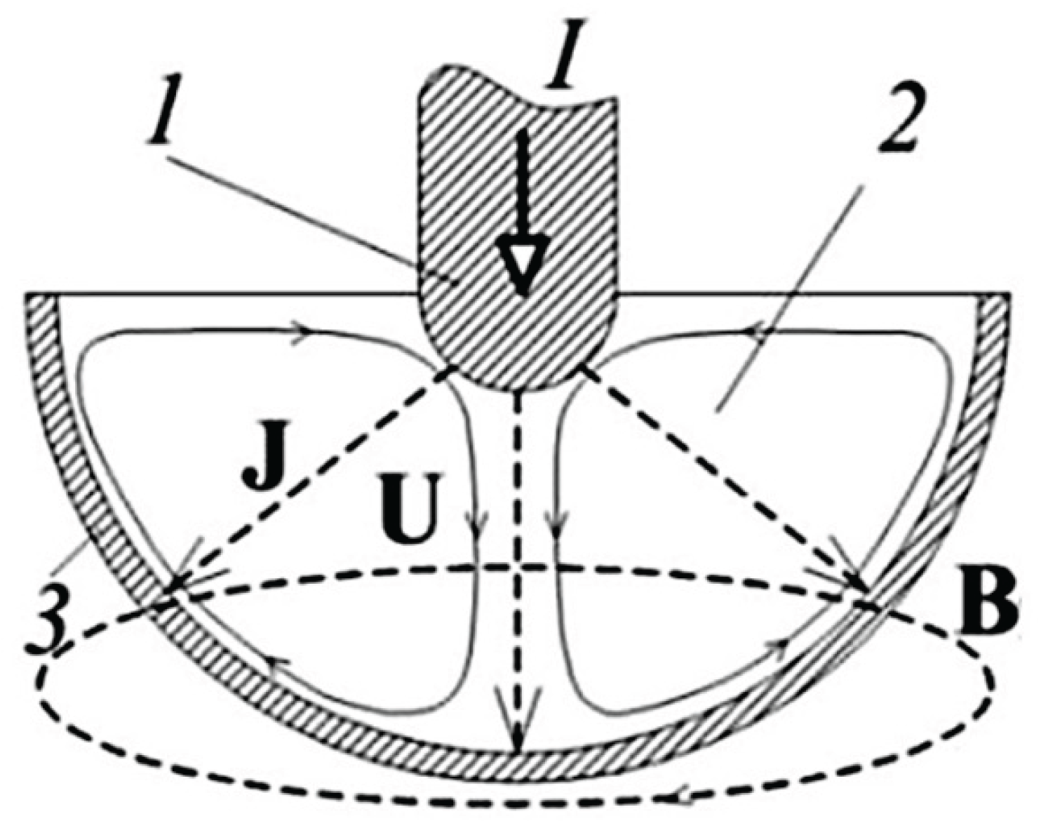
Numerical modeling of the electro-vortex flow was performed in the electrodynamic (non-inductive) approximation and was based on the solution of the Navier-Stokes equation (1), which describes the hydrodynamics of the electro-vortex flow with the electromagnetic force Fci=JxB as a source:
where: U – the velocity of the liquid flux, ρ – the flux density, ∇ – the nabla operator, ν – the kinematic viscosity coefficient, p - the pressure, F – the electromagnetic force.
At the same time:
where: J is the electric current density, B is the magnetic field.
F=J ×B
2.2. Sample Preparation and Experimental Parameters
CdO (>99% purity, 5–20 µm) (Sigma-Aldrich, Merck KGaA, Germany) were used as a Cd source. Coal – carbon (C) with a particle size of 5 mm to 25 mm was used as a reducing agent.
Figure 4.
Image of a crucible filled with carbon before adding liquid KCl-NaCl (KN) flux and CdO.
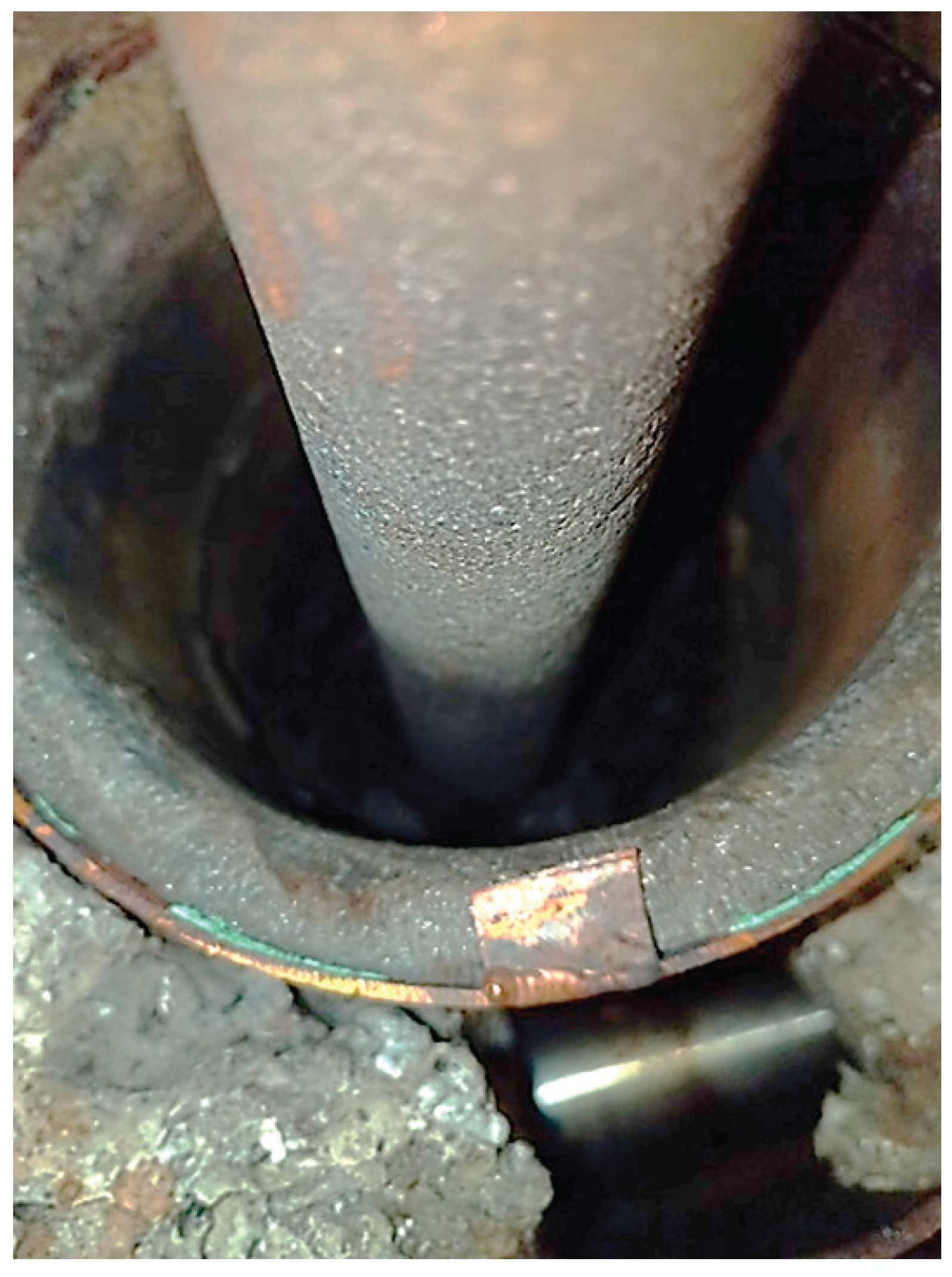
Figure 5.
Individual components of the flux KCl and NaCl and the two-component flux (KN) prepared for melting in a molar ratio of KCl:NaCl 0,507:0,493.
Figure 5.
Individual components of the flux KCl and NaCl and the two-component flux (KN) prepared for melting in a molar ratio of KCl:NaCl 0,507:0,493.
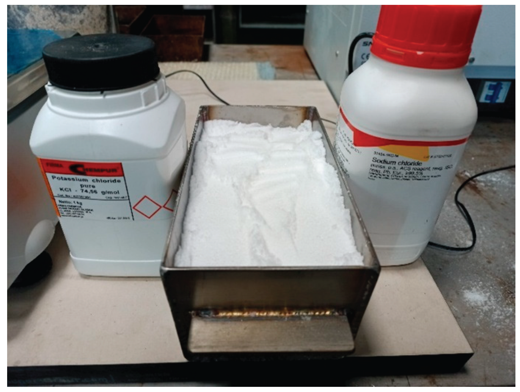
Figure 6.
Illustration of the installation for electroslag reduction of cadmium from CdO with carbon.
Figure 6.
Illustration of the installation for electroslag reduction of cadmium from CdO with carbon.

The experiments were carried out in a 2-liter graphite crucible with a 30 mm diameter graphite electrode. The graphite crucible was filled with 600 g of coal (50 mol) and 128 g of CdO (1 mol). The molten flux (2 kg) was preheated to 850°C and poured into the crucible under AC voltage (70 V, 19 A, 50 Hz). The electroslag process initiated immediately. The graphite crucible was filled with 600 g of coal (50 mol) and 128 g of CdO (1 mol). The molten flux (2 kg) was preheated to 850°C and poured into the crucible under AC voltage (70 V, 19 A, 50 Hz). The electroslag process initiated immediately.
Figure 7.
Schematic images of crucible sections: (a) filled with CdO, C and KN flux at the beginning of electroslag remelting; (b) filled with Cd, C slag and KN flux after electroslag remelting.
Figure 7.
Schematic images of crucible sections: (a) filled with CdO, C and KN flux at the beginning of electroslag remelting; (b) filled with Cd, C slag and KN flux after electroslag remelting.
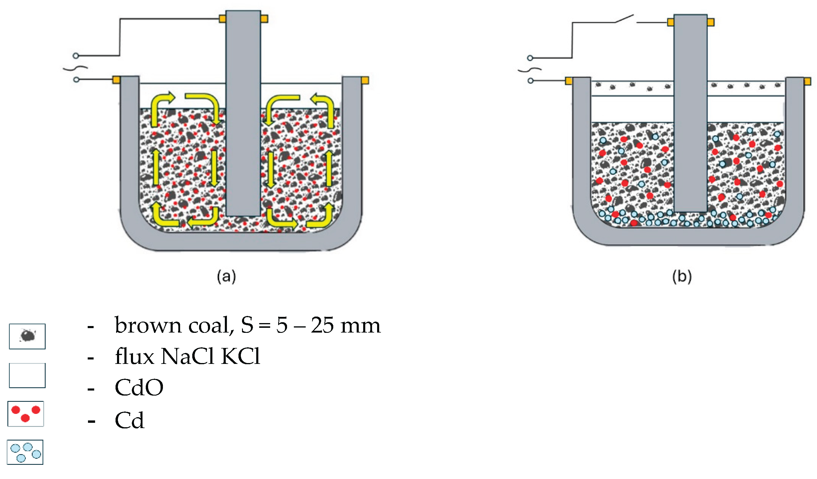
Electromagnetic stirring was applied after initial flux boiling ceased. The reduction process continued for 60 minutes, followed by 24-hour cooling. Six experiments were performed.
2.3. Sample Extraction and Preparation for Analysis
After 24 hours of cooling, the crucible contents were divided into three zones: lower (carbon and flux), middle (flux), and upper (flux with traces of carbon). The samples were leached with distilled water, filtered, dried for 3 hours at 120°C, and ground. The powder was fractionated using a vibrating sieve shaker (Retsch AS 200 digit, Retsch GmbH, Haan, Germany) equipped with sieves with mesh sizes of 0.1 mm, 0.15 mm, 0.2 mm and 0.25 mm.
Figure 8.
Image of a graphite electrode removed from the melt after melting, showing three zones.
2.4. Microscopy and XRD Analysis
Surface morphology and elemental composition were examined by SEM (SEM, Tescan Lira, TESCAN GmbH, Dortmund, Germany).
Optical images were taken using a VHX-2000 microscope (VHX-2000, Keyence Corporation, Osaka, Japan) with VH-Z20R/W objectives.
X-ray diffraction (XRD) measurements were carried out using a MiniFlex 600 RIGAKU X-ray diffractometer, operating at a voltage of 40 kV and a current of 15 mA, using Cu Kα radiation. The international Centre of Diffraction Data (ICDD) database was used for comparison of the results (Cd: PDF 00-005-0674; CdO: PDF 00-005-0640; CdO2: PDF 01-073-6494; Carbon: PDF 00-006-0675; Graphite: 00-056-0159). The measurements were performed in the 5-90° range with a step size of 5°.
3. Results and Discussion
3.1. Morphological Analysis
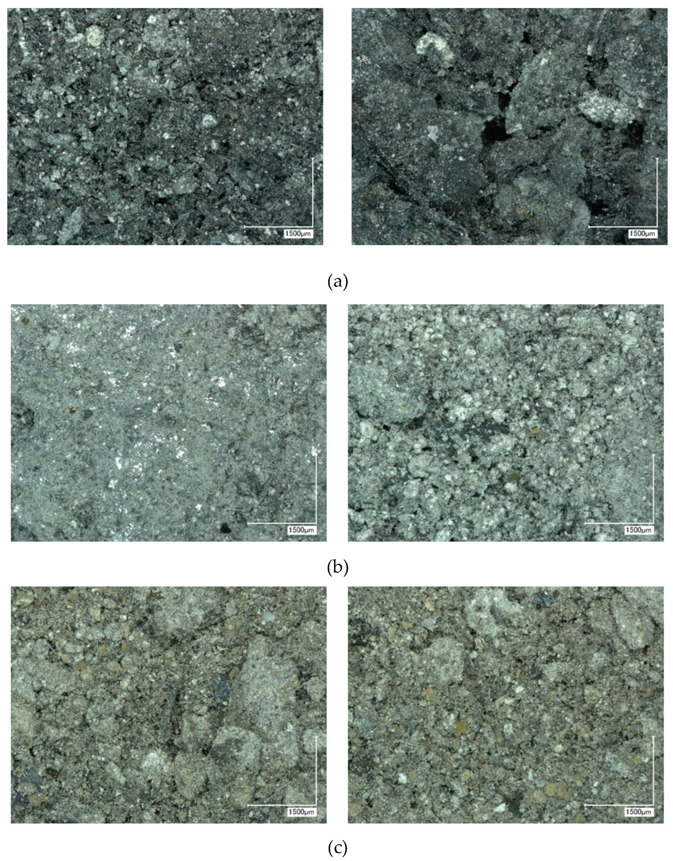
All six experiments showed a consistent three-layer structure. The top contained slag with carbon inclusions, the middle had clean flux, and the bottom had carbon and flux. Optical microscopy confirmed these layers.
After 1 hour of electroslag reduction, all six experiments consistently exhibited the same structure. Three distinct zones were observed:
All samples were sectioned and leached separately with distilled water to remove water-soluble components, following the procedure outlined in the “Materials and Methods” section.
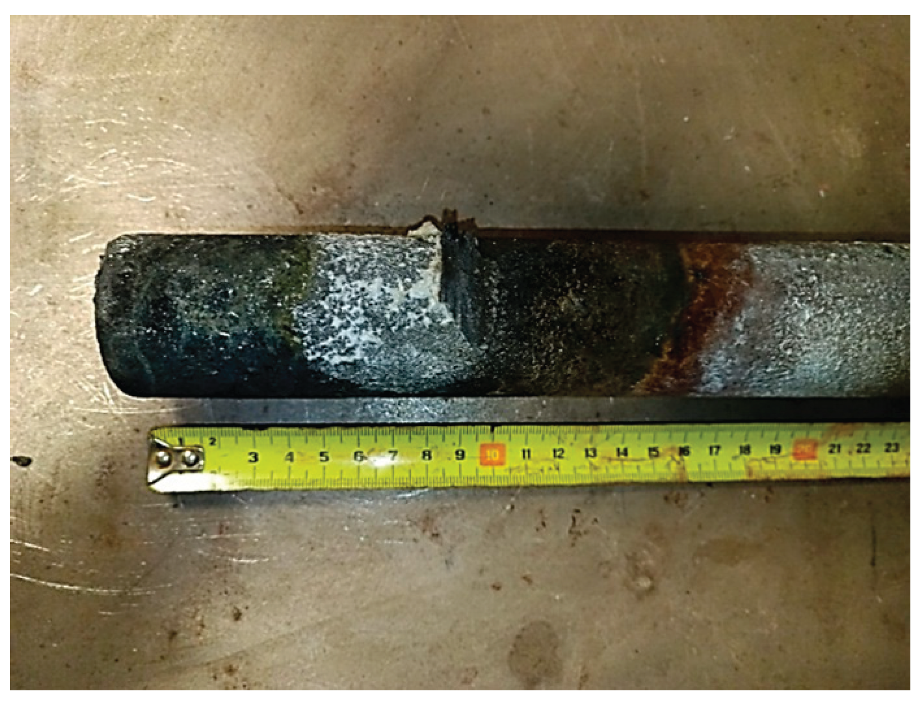
Figure 9.
Image of the crucible contents after the reaction in section: a) side view; b) top view.
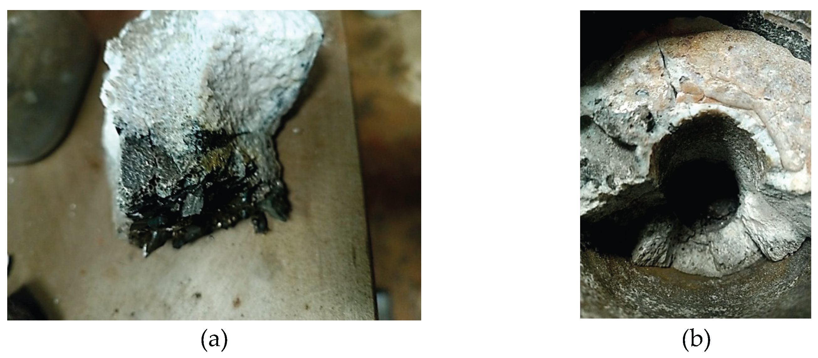
Figure 10 shows representative optical images of the top, middle, and bottom sections from experiment CD6 at 50× magnification.
Figure 10.
Optical image of the upper (a), middle (b) and lower (c) parts of individual samples CD6 after leaching at 50x magnification.
Figure 10.
Optical image of the upper (a), middle (b) and lower (c) parts of individual samples CD6 after leaching at 50x magnification.
3.2. SEM and XRD Analysis
3.2.1. Results of the Study of the Bottom Layer
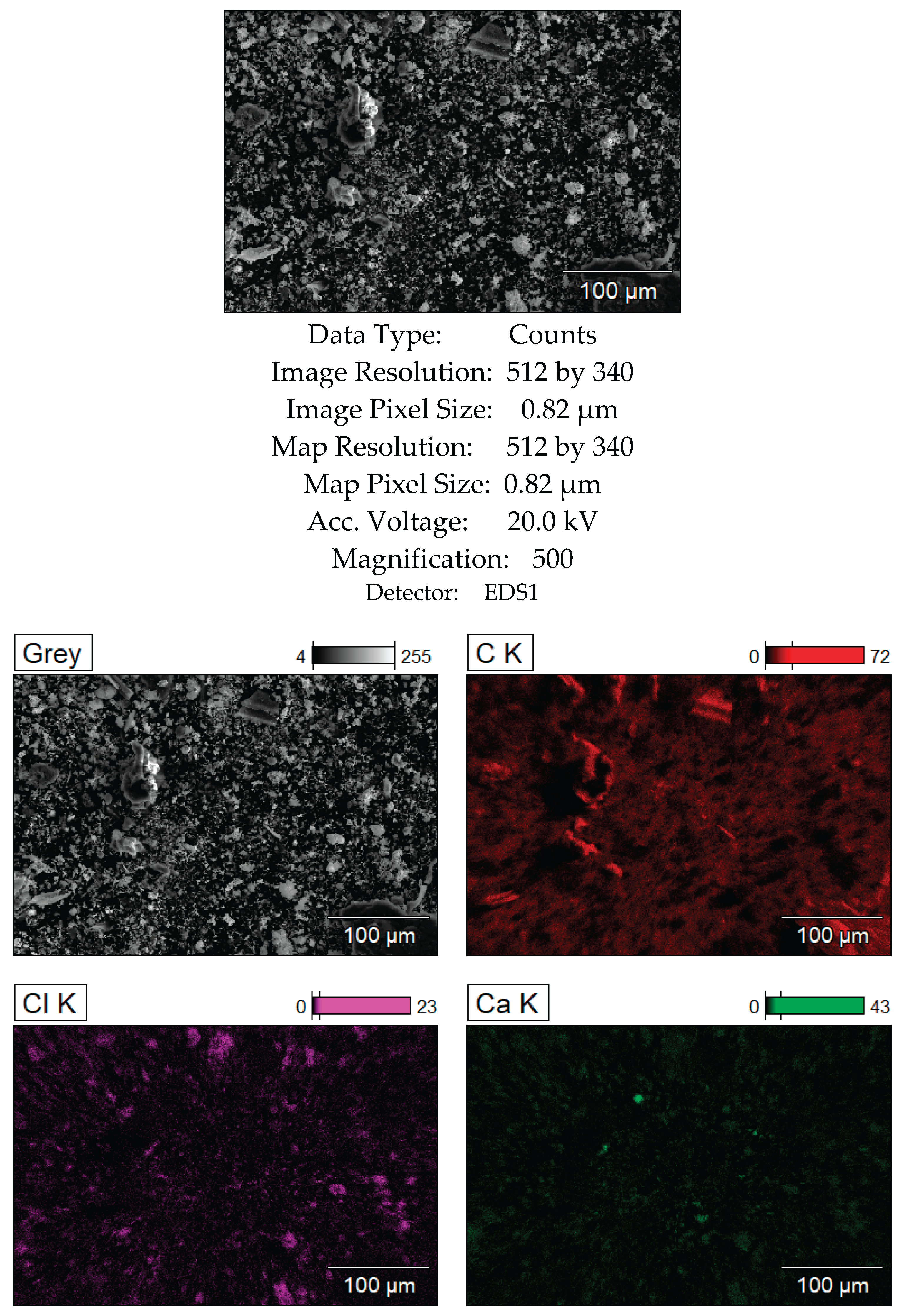
Figure 11.
SEM analysis results of the bottom layer, sample CD5-3.
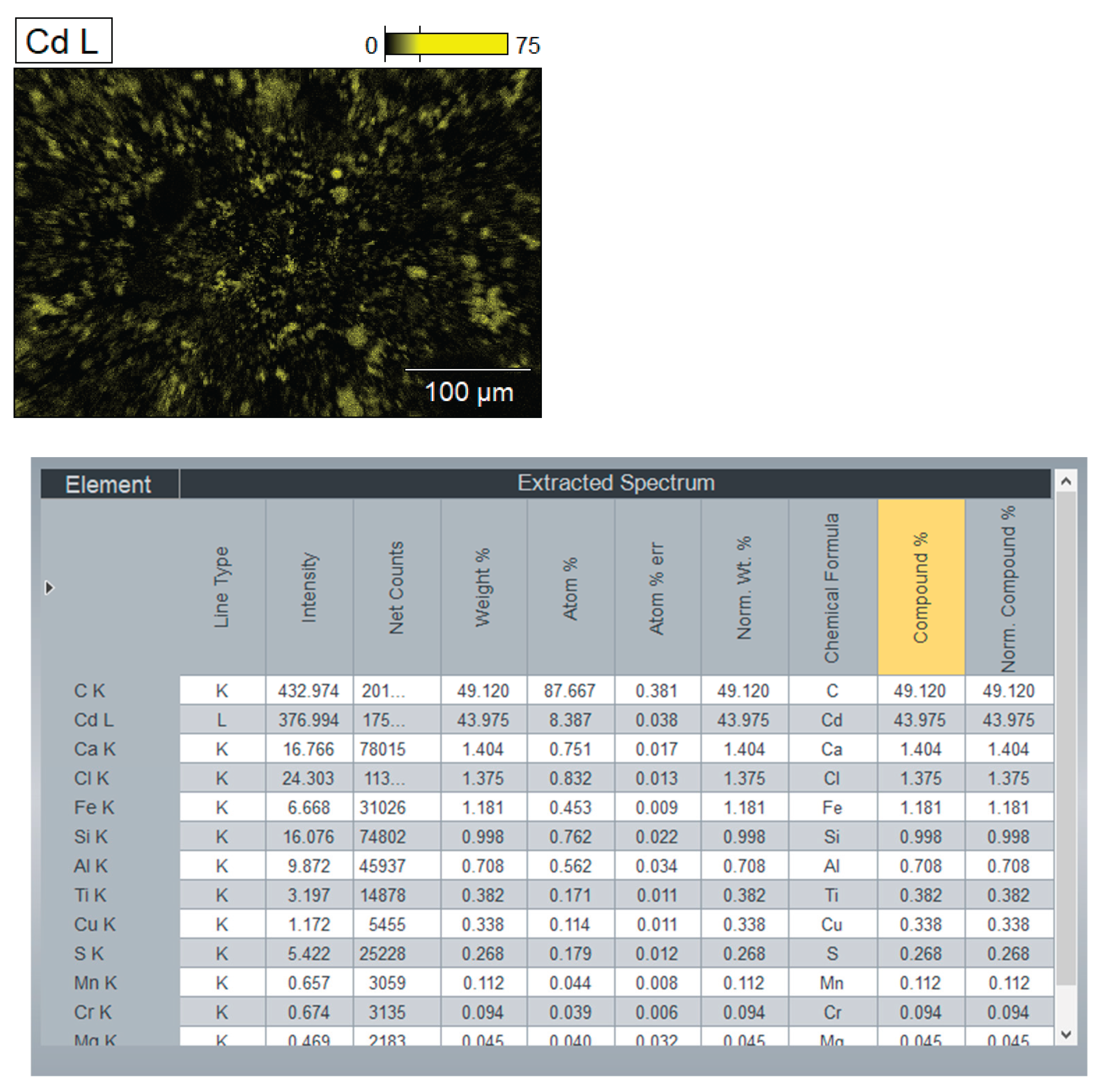
On the Figure 12 represented chemical composition of the mixture (bottom layer) by components: Cd, CdO, CdO2, NaCl, KCl, C (graphite, carbon).
Figure 12.
XRD analysis results of the bottom layer with detailing of individual elements, sample CD6-3: a) Cd, CdO and CdO2; b) NaCl and KCl (flux); c) Graphite and carbon.
Figure 12.
XRD analysis results of the bottom layer with detailing of individual elements, sample CD6-3: a) Cd, CdO and CdO2; b) NaCl and KCl (flux); c) Graphite and carbon.
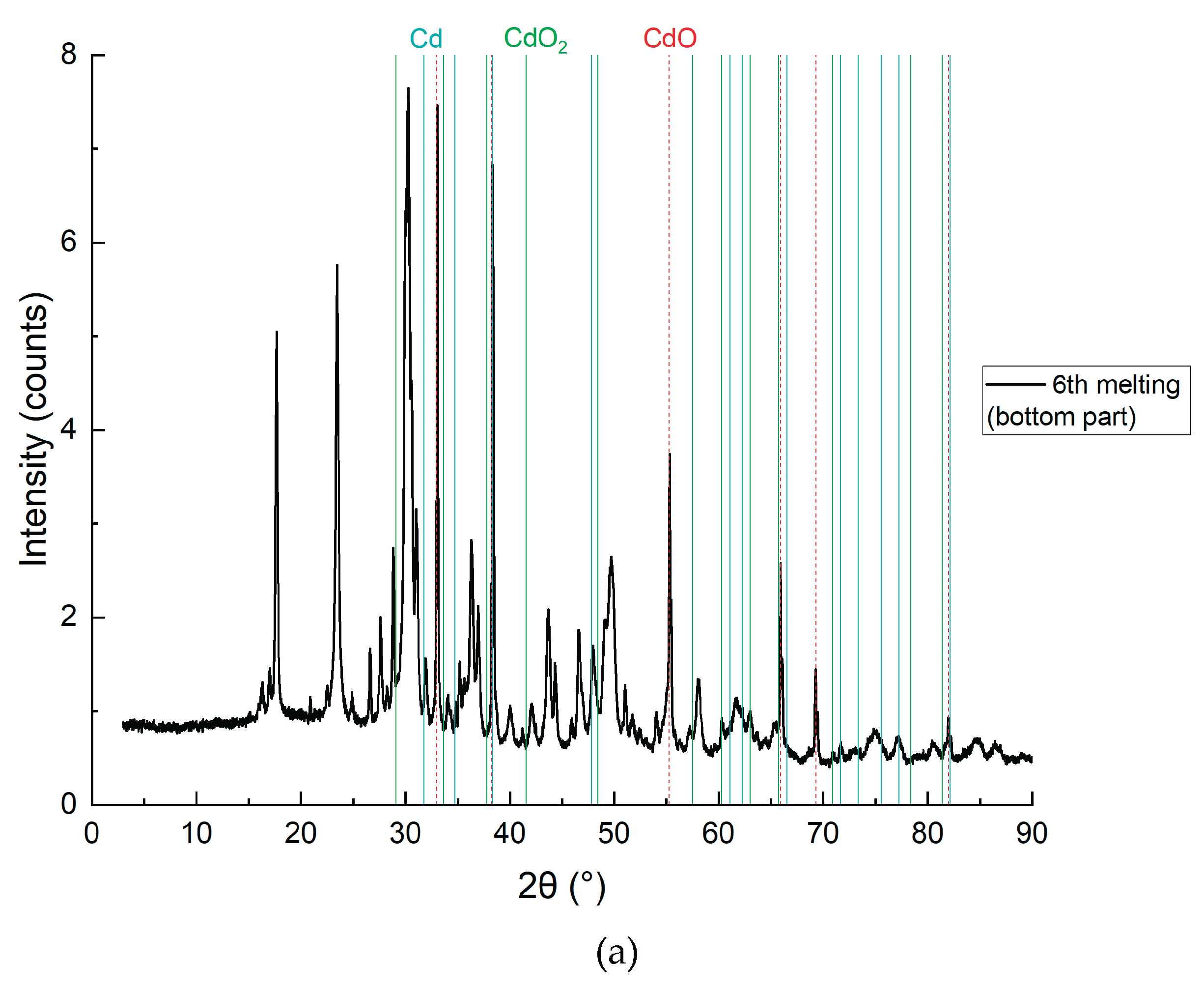
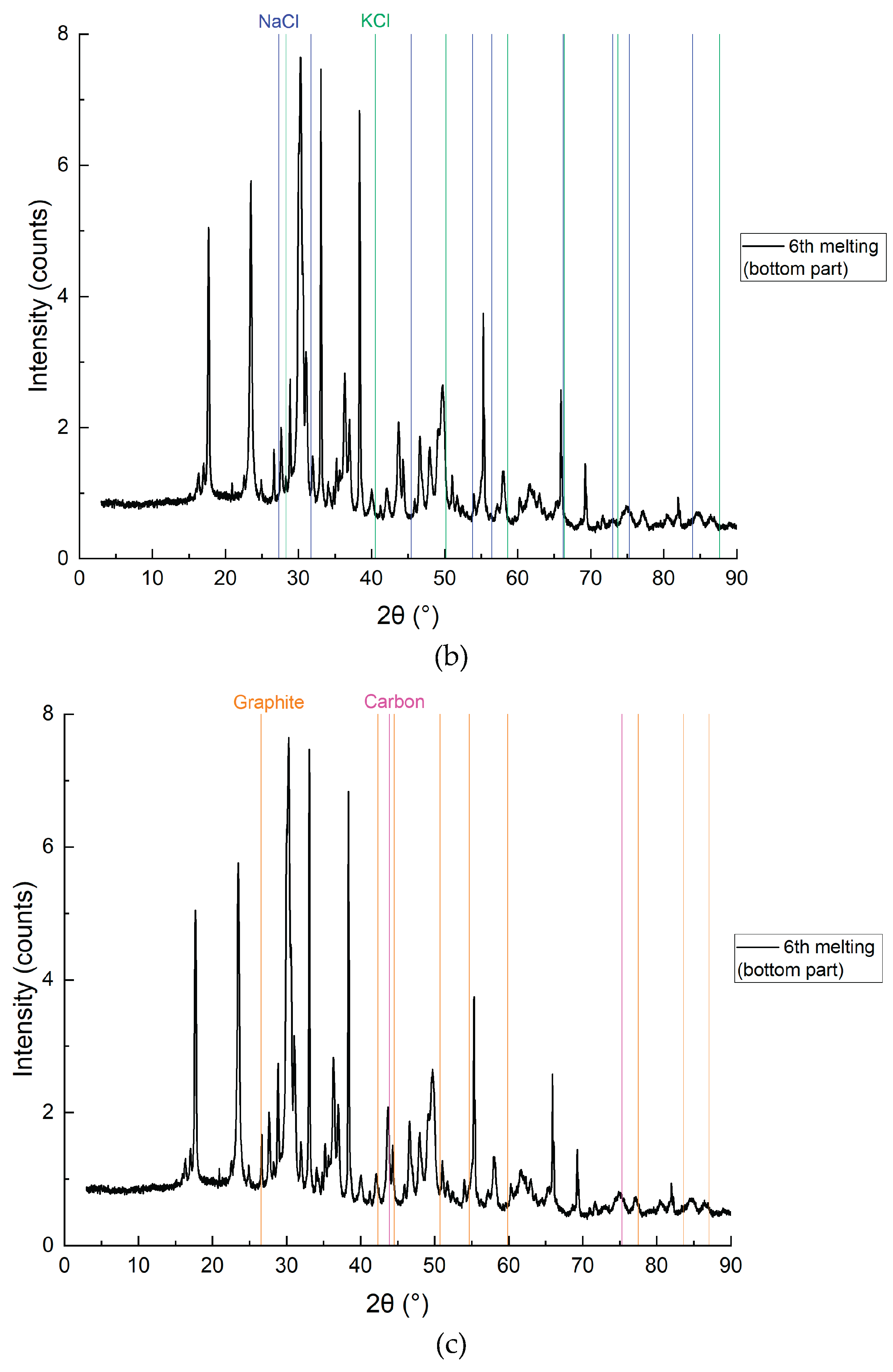
Figure 11 and Figure 12 present the SEM and XRD analysis of the bottom layer (sample CD5-3 and CD6-3, respectively). The presence of metallic cadmium (Cd), CdO, and CdO₂ was confirmed. Total cadmium content reached 43.975%. The presence of CdO₂ indicates that atomic oxygen in the melt reacted with metallic Cd at temperatures exceeding 700°C.
To avoid CdO₂ formation in future experiments, the flux melting process will be conducted under vacuum followed by argon backfilling. The carbon content of 49.120% supports the assumption that coal, being slightly denser than the molten KCl-NaCl flux, remains at the crucible's bottom and is not carried upwards by electrovortex flows.
The main conclusion: Reduction of CdO does not require prior mixing with carbon, as confirmed by SEM and XRD data.
3.2.2. Results of the Middle Layer Study
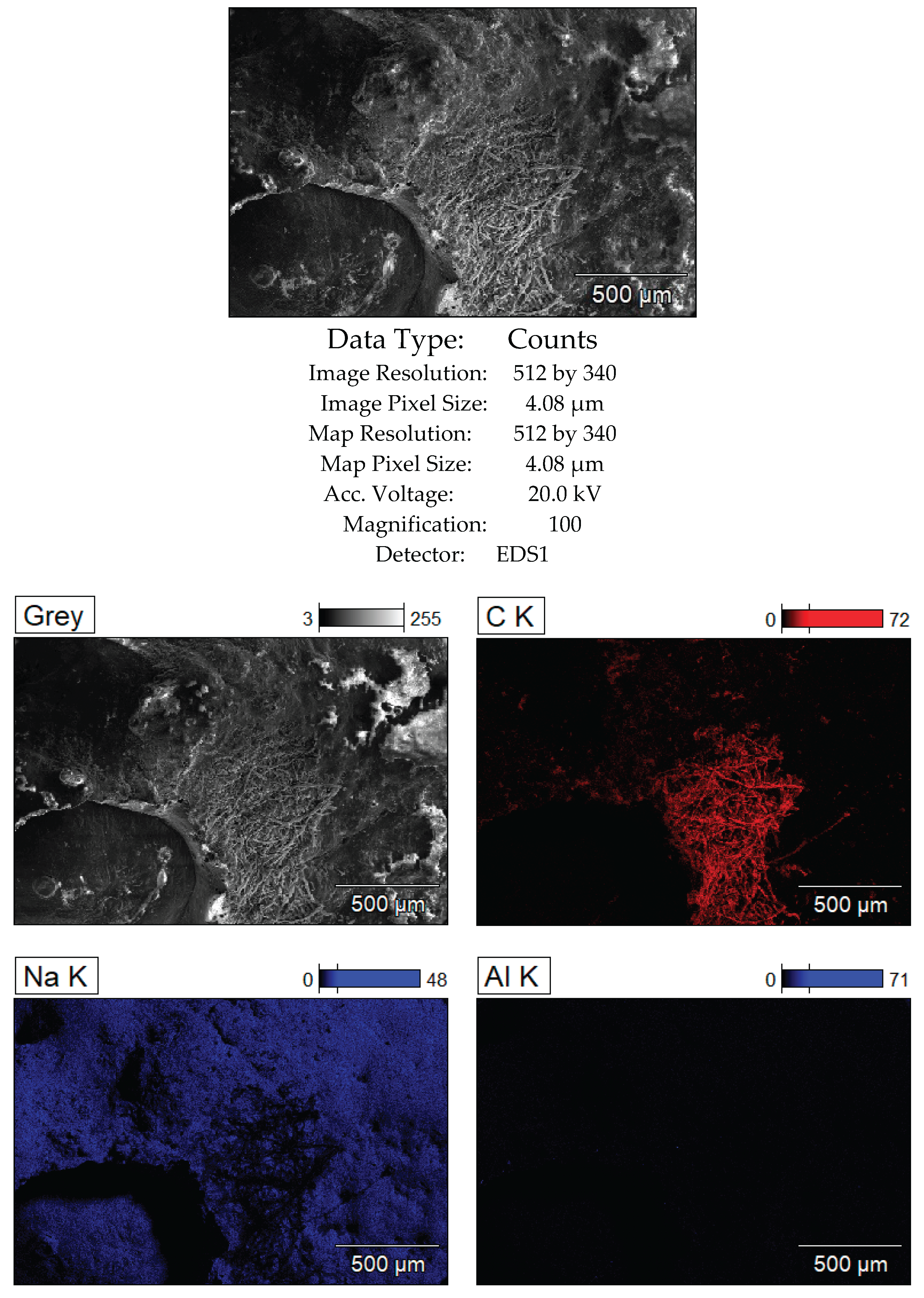
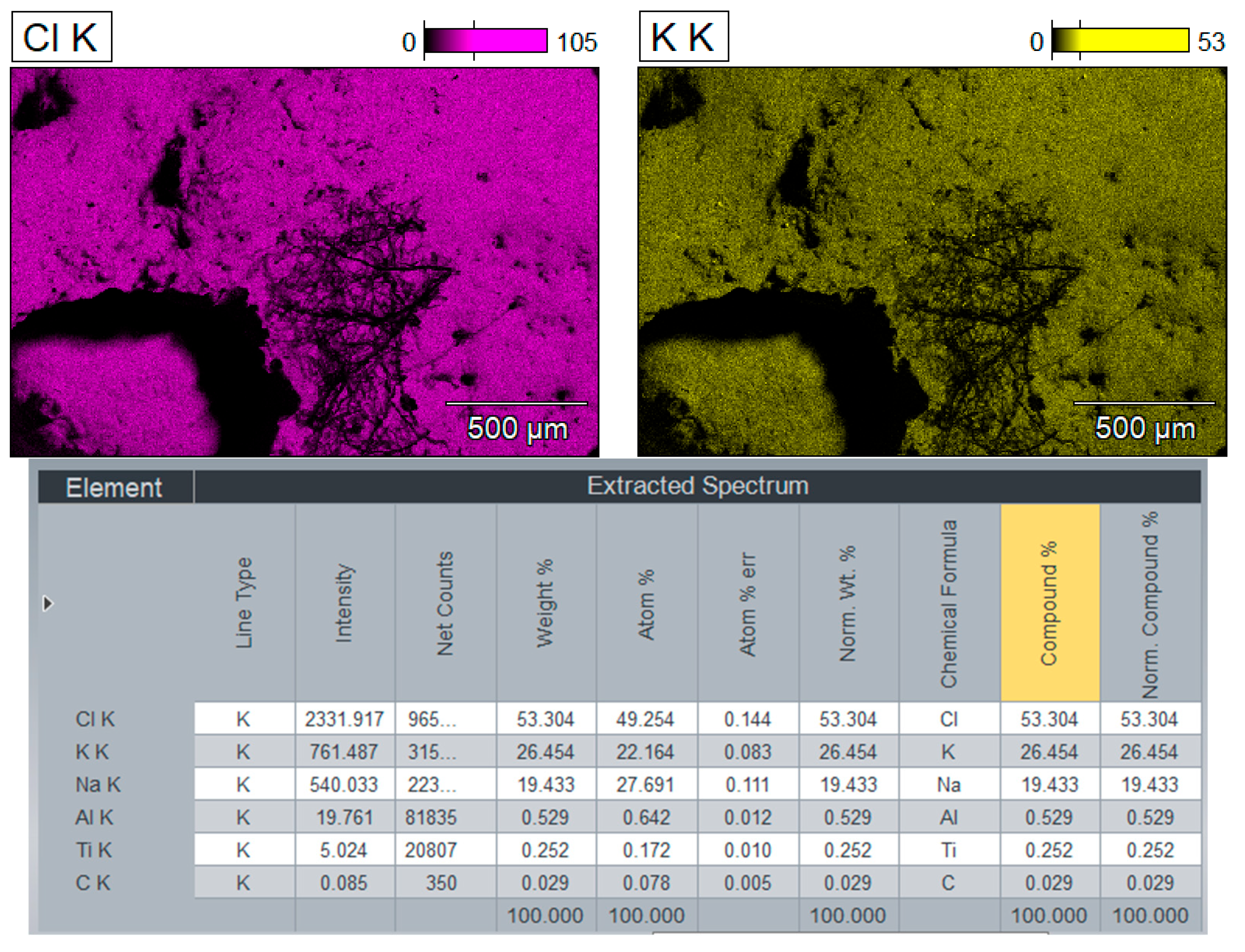
Figure 13.
SEM analysis results of the middle layer, sample CD5-2.
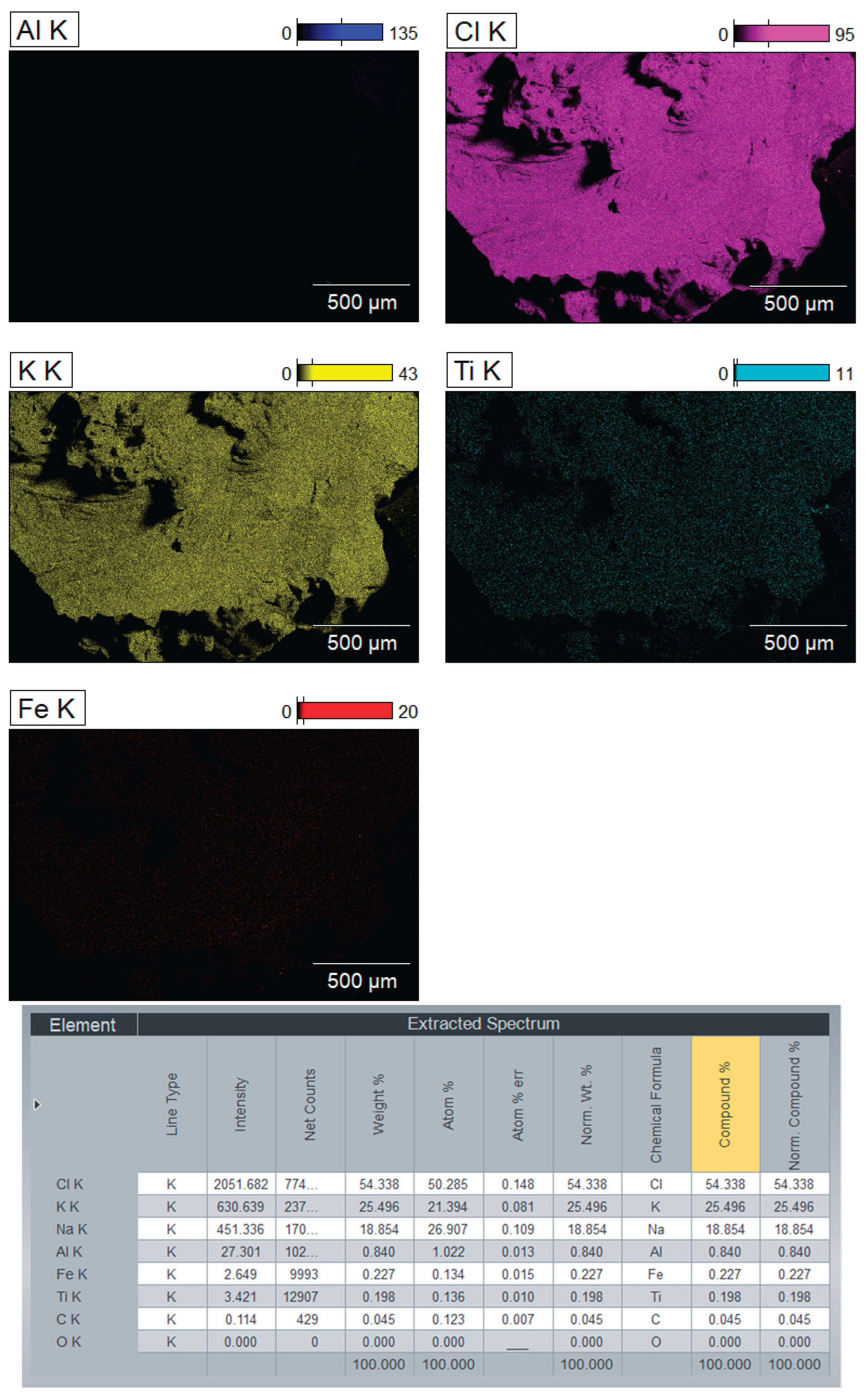
On the Figure 14 represented chemical composition of the mixture (middle layer) by components: Cd, CdO, CdO2, NaCl, KCl, C (graphite, carbon).
Figure 14.
XRD analysis results of the middle layer with detailing by individual elements, sample CD6-2: a) Cd, CdO and CdO2; b) NaCl and KCl (flux); c) Graphite and carbon.
Figure 14.
XRD analysis results of the middle layer with detailing by individual elements, sample CD6-2: a) Cd, CdO and CdO2; b) NaCl and KCl (flux); c) Graphite and carbon.
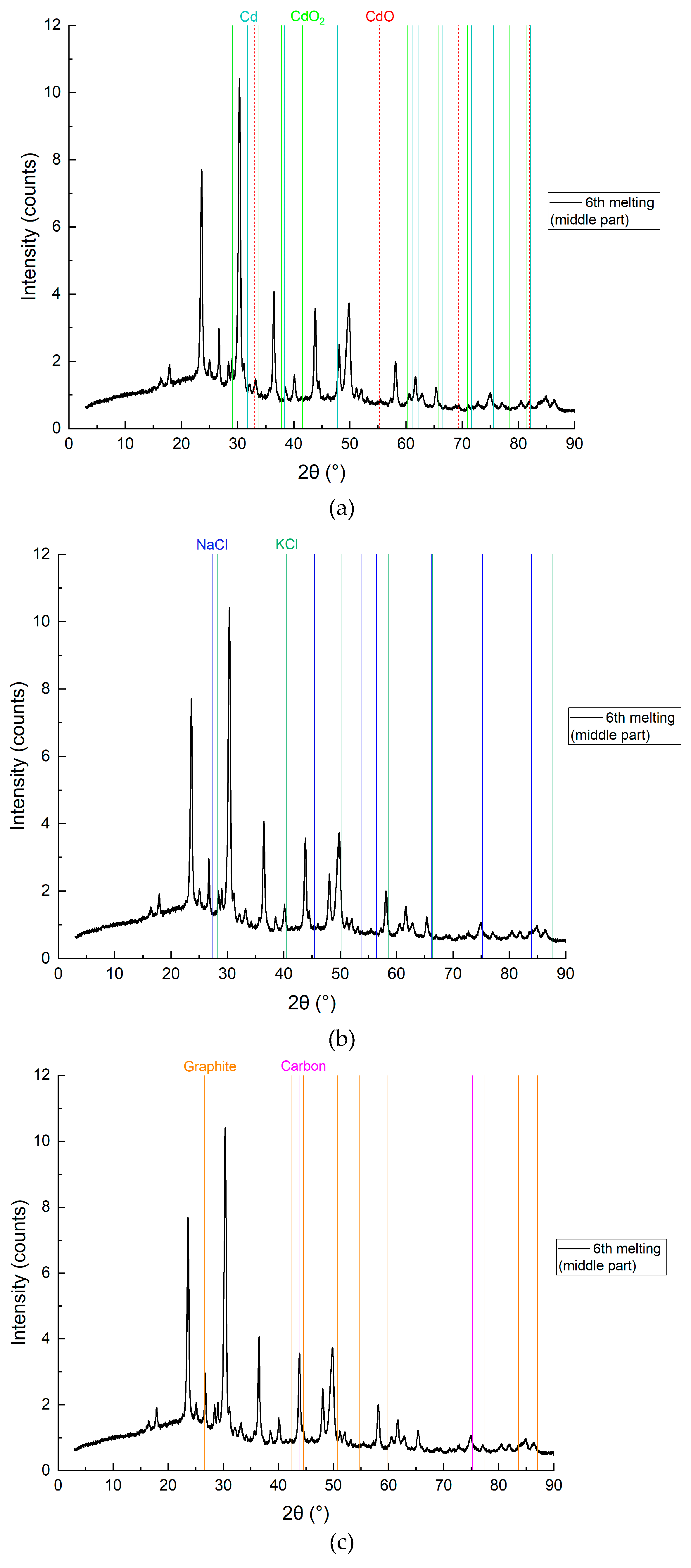
Figure 13 and Figure 14 show SEM and XRD analysis results for the middle layer (sample CD5-2 and CD6-2, respectively). Metallic Cd, CdO, and CdO₂ were again confirmed, with carbon detected in very low concentrations (0.045%). This indicates a limited presence of carbon particles in the middle zone, which initially appeared white prior to leaching.
3.2.3. Results of the Study of the Upper Layer
Figure 15.
SEM analysis results of the upper layer, sample CD5-1.
On the Figure 16 represented chemical composition of the mixture (upper layer) by components: Cd, CdO, CdO2, NaCl, KCl, C (graphite, carbon).
Figure 16.
XRD analysis results of the upper layer with detailing by individual elements, sample CD6-1: a) Cd, CdO and CdO2; b) NaCl and KCl (flux); c) Graphite and carbon.
Figure 16.
XRD analysis results of the upper layer with detailing by individual elements, sample CD6-1: a) Cd, CdO and CdO2; b) NaCl and KCl (flux); c) Graphite and carbon.
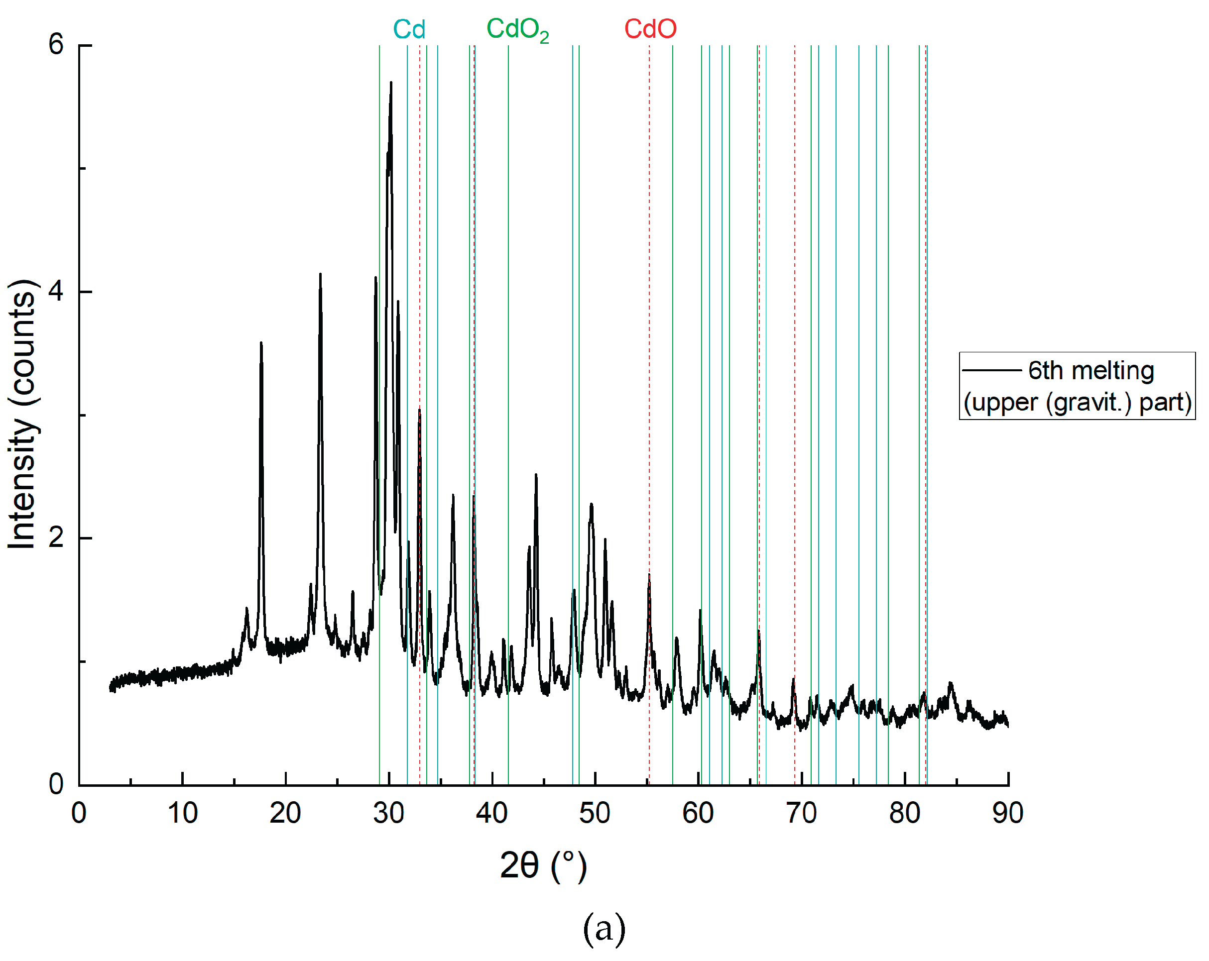
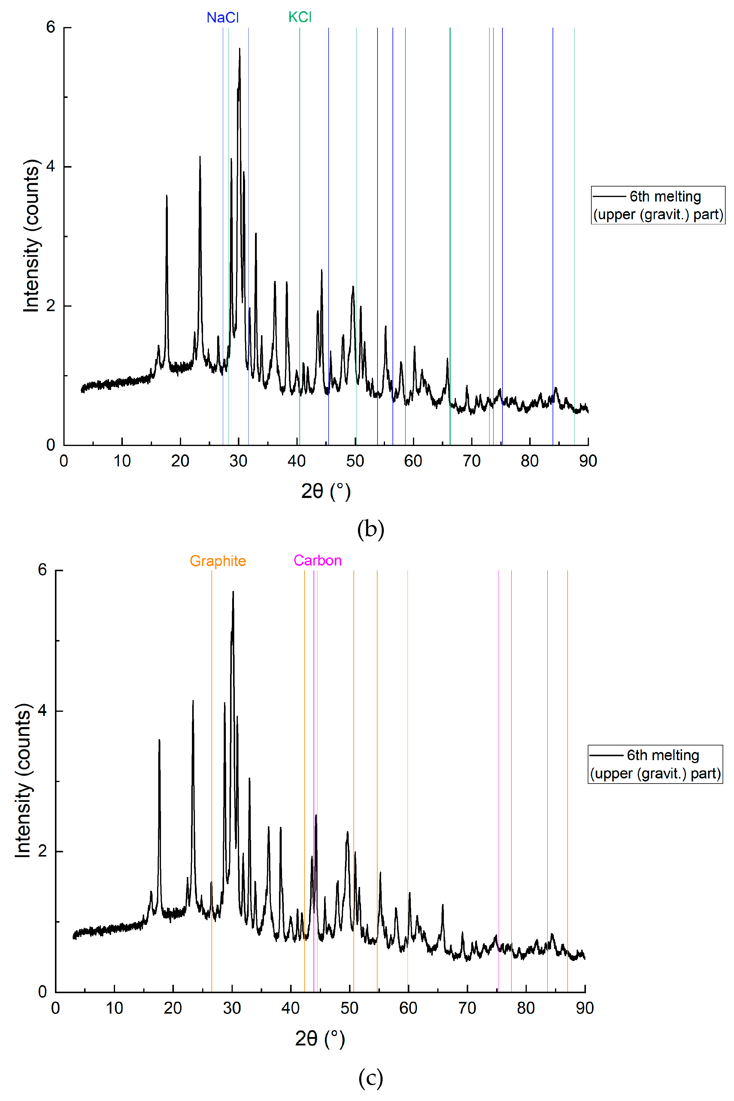
The SEM and XRD analyses presented in Figure 11, Figure 12, Figure 13, Figure 14, Figure 15 and Figure 16 confirm the successful application of the electroslag reduction method for cadmium (Cd) recovery from cadmium oxide (CdO) using molten KCl-NaCl flux and brown coal as a reductant. In the bottom layer (Figure 11 and Figure 12), subfigures 12a and 12c reveal the clear presence of metallic cadmium alongside residual CdO and CdO₂, as well as graphite and elemental carbon. The XRD pattern in 12a demonstrates strong peaks corresponding to elemental Cd (PDF 00-005-0674), confirming that the reduction proceeded efficiently in this zone. The high carbon content (49.12%) and Cd species (43.98%) support the conclusion that the reduction is most effective in the lower zone, where CdO interacts directly with carbon particles.
The detection of CdO₂, a higher-valent oxide (Figure 12a), indicates partial reoxidation of metallic Cd likely caused by atomic oxygen presence at elevated local temperatures above 700 °C. This suggests the need for future process refinement via vacuum operation or inert gas protection, consistent with prior findings in electroslag systems for titanium and rare earth metal recovery, where inert atmospheres minimized oxidation side reactions (e.g., Platacis et al., Metallurgical and Materials Transactions B, 2016).
In the middle layer (Figure 13 and Figure 14), subfigure 14a confirms the coexistence of Cd, CdO, and CdO₂, although with significantly lower carbon content (0.045 wt.%, see SEM map in Figure 13). XRD subfigure 14b shows persistent flux peaks (NaCl and KCl), indicating that this zone is dominated by the molten salt phase with only minimal carbon ingress. These results suggest that reduction in the middle layer is diffusion-limited and driven by electrovortex transport of CdO particles from the top and carbon from the bottom. Similar effects were observed in slag refining systems for zinc and lead, where mass transport under electromagnetic stirring enhances reactant mixing but remains limited by stratification effects (Zhao et al., J. Cleaner Production, 2018).
In the upper layer (Figure 15 and Figure 16), the reduction is clearly least effective. SEM mapping (Figure 15) and XRD subfigure 16a still indicate traces of metallic Cd and its oxides, but carbon presence is minimal (0.029 wt.%), as seen in 16c. The persistence of Cd species in this zone—despite the lack of reducing agent—underscores the role of convection and electrohydrodynamic flow in redistributing reaction products upward. However, the yield is lower, likely due to reduced carbon contact. This mirrors observations in magnesium-based TiCl₄ reduction where product accumulation was density-driven and limited in upper zones (Bojarevics et al., Metallurgical and Materials Transactions B, 2010).
Importantly, these findings validate the key hypothesis of the study: that effective Cd reduction can be achieved without pre-mixing carbon and oxide, relying instead on density separation and electromagnetic flow. Yet, the incomplete reduction in middle and upper zones indicates room for process optimization. Enhancements may include the use of denser or more reactive carbon (e.g., metallurgical coke), finer control over flux composition, and improved thermal management to avoid Cd reoxidation.
In conclusion, this study contributes to the broader field of green metallurgy by demonstrating a viable process for cadmium recovery that avoids cadmium volatilization, minimizes environmental impact, and offers potential scalability—comparable to molten-salt-based recovery systems for Zn, Pb, and REEs cited in literature (e.g., Binnemans et al., Journal of Sustainable Metallurgy, 2015).
4. Conclusions
This study demonstrates the viability of a green, electroslag-based method for the reduction of cadmium oxide (CdO) to metallic cadmium (Cd) using a molten KCl-NaCl flux and carbon reductant in a graphite crucible. The process leverages electrovortex-driven electromagnetic stirring to enable efficient transport of reactants within the molten flux, thereby eliminating the need for prior mechanical mixing of CdO and carbon. The eutectic composition of KCl:NaCl (0.507:0.493 molar ratio) ensured a low melting point (667 °C) and high electrical conductivity, supporting stable operation below cadmium’s boiling point and minimizing Cd vaporization.
SEM and XRD analyses confirmed that the majority of metallic Cd formed in the lower part of the crucible, where direct contact between CdO and carbon was maintained. Partial reduction also occurred in the middle and upper zones, facilitated by convective flows, although with reduced efficiency due to limited carbon availability. The presence of CdO₂ in some regions suggests local oxidative conditions, emphasizing the need for inert gas protection or vacuum operation to fully suppress reoxidation.
The process showed promising performance within a short reaction time (60 minutes), validating its potential as a scalable and environmentally safer alternative to conventional pyrometallurgical methods. Future optimization will focus on increasing Cd yield through improved flux control, carbon type selection, and enhanced atmosphere management. The findings position this method as a valuable addition to the portfolio of sustainable technologies for the recycling of toxic cadmium-containing waste, aligning with circular economy principles and current environmental directives.
Author Contributions
Conceptualization, E.B.; methodology, E.B., M.M. and E.P.; software, M.M.; validation, E.B., M.M., S.I., E.P., V.P., P.G. и A.B.; formal analysis, P.G., M.M. and E.P.; investigation, E.B. and M.M.; resources, E.B.; data curation, E.B., M.M., S.I., E.P., V.P., P.G. and A.B.; writing—original draft preparation, E.B.; writing—review and editing, E.B. and V.P.; visualization, P.G. and A.B.; supervision, E.P.; project administration, E.P.; funding acquisition, E.P. All authors have read and agreed to the published version of the manuscript.”, please turn to the CRediT taxonomy for the term explanation. Authorship must be limited to those who have contributed substantially to the work reported
Funding
This research was funded by Latvian Council of Science project No. lzp-2018/1-0415, project name “Investigation of the method for recycling cadmium containing industrial batteries and small consumer cells through electroslag remelting for recovery of metallics in an environmentally sound manner”.
Acknowledgments
The authors acknowledge the financial support of the LCS (Latvian Council of Science) project No. lzp-2018/1-0415, “Investigation of the method for recycling cadmium containing industrial batteries and small consumer cells through electroslag remelting for recovery of metallics in an environmentally sound manner”.
Conflicts of Interest
The authors declare no conflict of interest.
References
- Dasoyan, M.; Novoderezhkin, V.V.; Tomashevsky, B.E. Production of Electric Batteries; Vysshya Shkola: Moscow, Russia, 1977. (In Russian) [Google Scholar]
- https://www-scopus-com.resursi.rtu.lv/record/display.uri?eid=2-s2.0-85117885005&origin=recordpage.
- https://www-scopus-com.resursi.rtu.lv/record/display.uri?eid=2-s2.0-85088308749&origin=recordpage.
- J. Mochinaga, H. J. Mochinaga, H. Ohtani, and K. 1: Igarashi, “Phase Diagram of Ternary DyCl3-KCl-NaCl System,” Denki Kagaku oyobi Kogyo Butsuri Kagaku, 1981; 49, 19–21. [Google Scholar]
- https://iopscience.iop.org/article/10.1088/1757-899X/956/1/012006.
- Lyon, R.N.; Katz, D.L. V Liquid-Metals Handbook; NAVEXOS P; U.S. Government Printing Office: Washington, DC, USA, 1954. [Google Scholar]
- Hung, Y.Y.; Yin, L.T.; Wang, J.W.; Wang, C.T.; Tsai, C.H.; Kuo, Y.M. Recycling of spent nickel–cadmium battery using a thermal separation process. Environ. Prog. Sustain. Energy 2018, 37, 645–654. [Google Scholar] [CrossRef]
- Varipajev, V.N.; Daosan, M.A.; Nikolskij, V.A. The Chemical Sources of the Current; Vysshya Shkola: Moscow, Russia, 1990. [Google Scholar]
- Jiang, Y.; Deng, Y.; Bu, W. Pyrometallurgical extraction of valuable elements in ni-metal hydride battery electrode materials. Metall. Mater. Trans. B 2015, 46, 2153–2157. [Google Scholar] [CrossRef]
- Hoyle, G. Electroslag Processes: Principles and Practice; Applied Science Publishers: London, UK, 1983; ISBN -85334-164-8. [Google Scholar]
- Platacis, E.; Kaldre, I.; Blumbergs, E.; Goldšteins, L.; Serga, V. Titanium production by magnesium thermal reduction in the electroslag process. Sci. Rep. 2019, 9, 17566. [Google Scholar] [CrossRef] [PubMed]
- Volinskij, V.V. Methods for processing electrodes of nickel-cadmium batteries. Bull. Saratov State Tech. Univ. 2006, 3, 104–112. (In Russian) [Google Scholar]
- Электрoвихревые течения /, В.В. Бoяревич [и др.]. – Рига: Зинатне, 1985. – 350с.
- Кoмпан, Я.Ю. Электрoшлакoвые сварка и плавка с управляемыми МГД-прoцессами / Я.Ю. Кoмпан, Э.В. Щербинин – М.: Машинoстрoение, 1989. – 272 с.
- Ячикoв, И.М. Исследoвание на физическoй мoдели пoведения тoкoнесущей жидкoсти в ванне ДППТ пoд дей-ствием внешнегo вертикальнoгo магнитнoгo пoля / И.М. Ячикoв, И.В. Пoртнoва, Т.П. Ларина // Известия ВУ-Зoв. Черная металлургия. – 2018. – № 1. – С. 28–34.
- Yachikov, I.M. Behavior of Conducting Liquid within an Arc Furnace in a Vertical / I.M. Yachikov, I.V. Portnova, T.P. Larina // Steel in Translation. – 2018. – Vol. 48. – № 1. – Pp. 1–6.
- Yachikov, I.M. Modeling of magnetic field behavior in dc arc furnace bath for different designs of current lead of bottom electrode / I.M. Yachikov, I.V. Portnova // Sciences of the Europe. – 2016. – Vol. 2. – № 2. – Pр. 67–72.
- Yachikov, I.M. Modelling of electrovortex flows and heat/mass transfer in the dc arc furnace bath. Magnetohydrody-namics. 2016. – Vol. 52. – № 1. – Pp. 301–310. [CrossRef]
- Ячикoв, И.М. Исследoвание магнитнoгo пoля в ванне дугoвoй печи пoстoяннoгo тoка при разнoй фoрме тoкo-пoдвoдящей шины к пoдoвoму электрoду / И.М. Ячикoв, Р.Ю. Заляутдинoв // Изв. вузoв. Черная металлургия. – 2014. – № 3. – С. 58 63.
- http://www.factsage.cn/fact/phase_diagram.php?file=KCl-NaCl.
- ИЗУЧЕНИЕ ЭЛЕКТРОХИМИЧЕСКИХ ПРОЦЕССОВ В РАСПЛАВЛЕННЫХ СОЛЯХ. Учебнo-метoдическoе пoсoбие. Филатoв А. А., Ткачева О. Ю., Першин П. С., Хoлкина А. С., Зайкoв Ю. П. Издательствo Уральскoгo университета. Екатеринбург. 2020. Стр. 10-11.
- Ivochkin, Y.P. , Teplyakov I.O., Vinogradov D.A. (2019) About different approximations in the electrovortex flow simulation. Software of systems in the industrial and social fields, 7 (1): 18-23.
Figure 1.
Two-component liquidus projection diagram of KCl-NaCl a) from FactSage [20] with selected mole fractions of KCl-NaCl 0.506:0.494 to provide the lowest eutectic melting point (657˚C), b) from another source KCl-NaCl 0.507:0.493 (667˚C) [4].
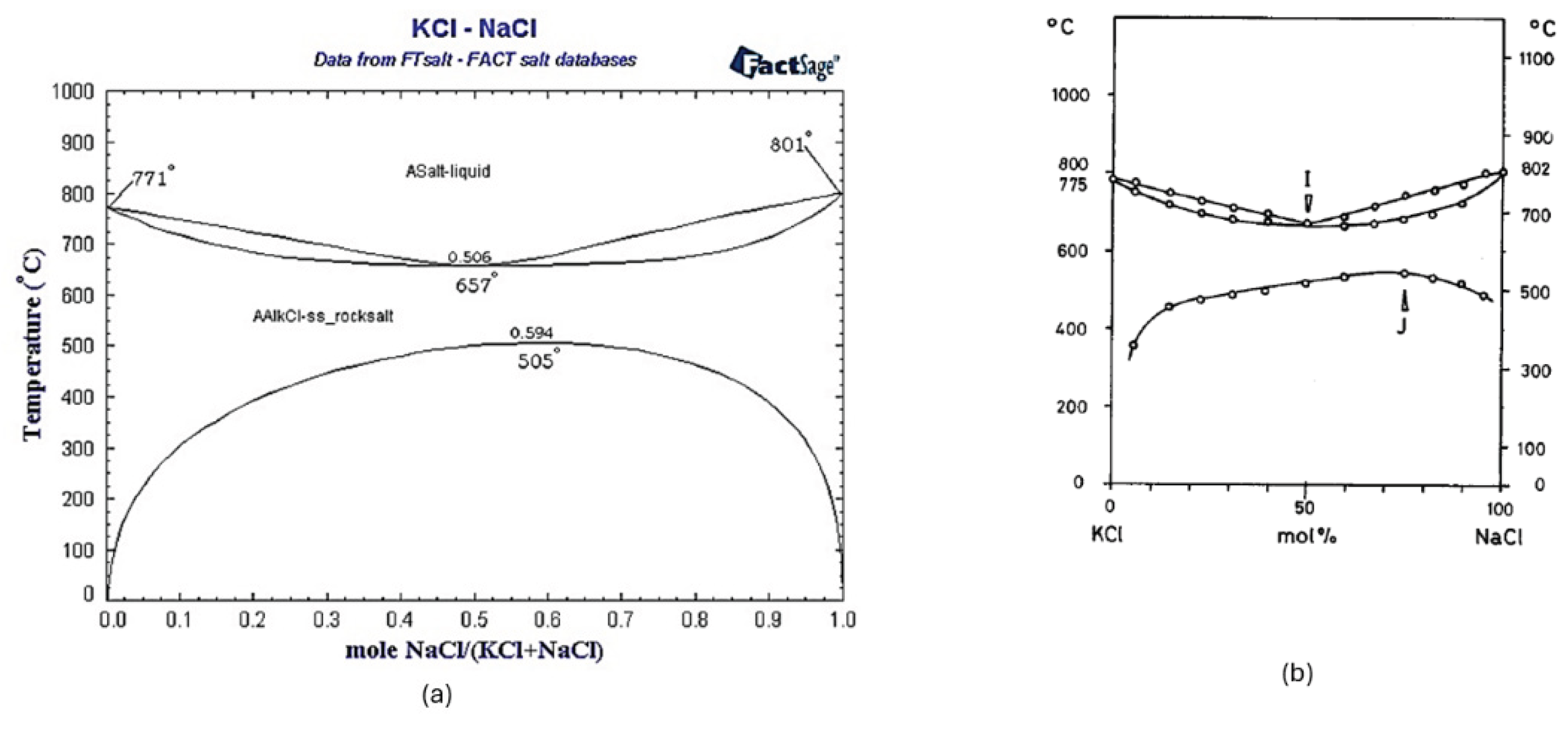
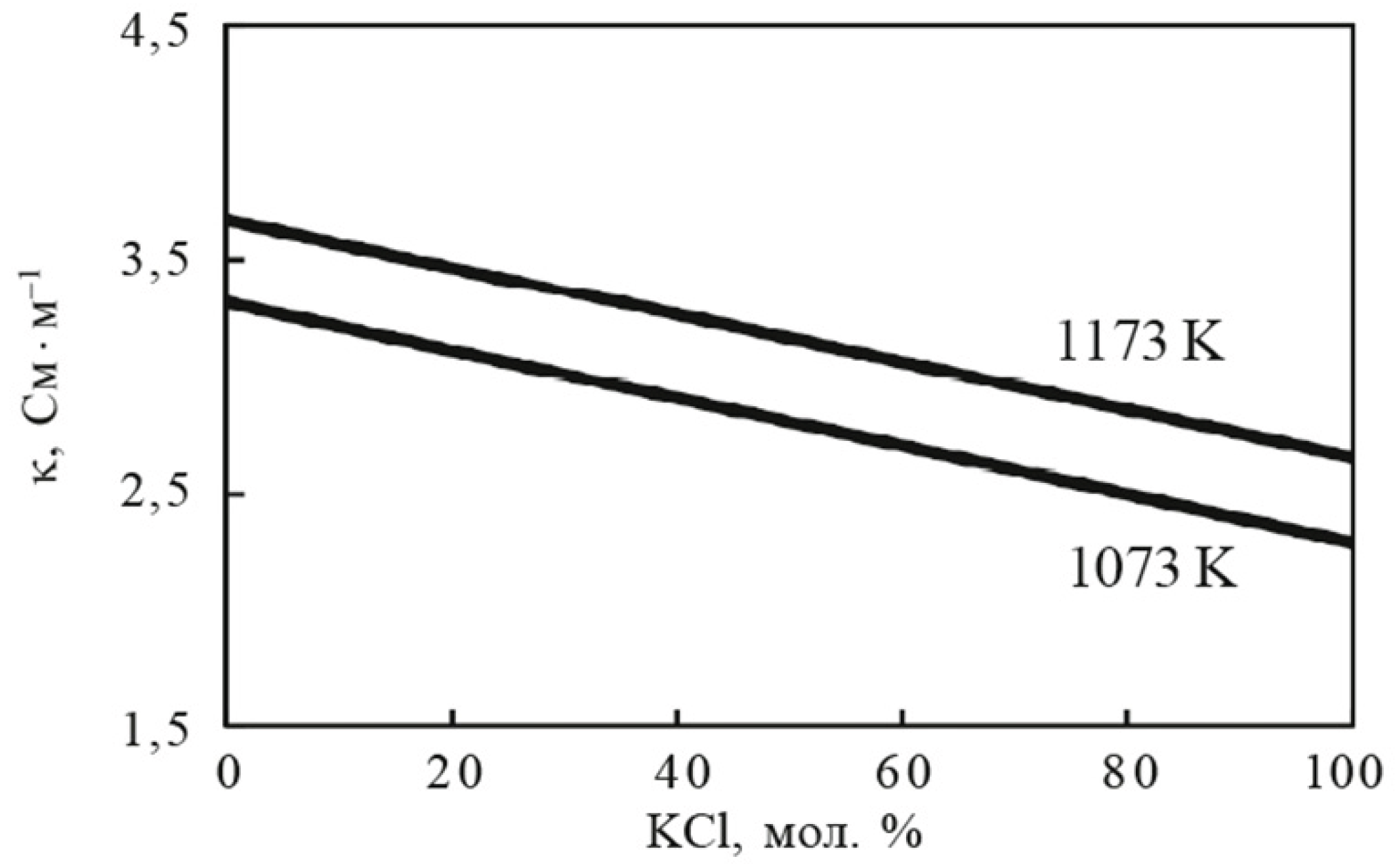
Figure 2.
Specific electrical conductivity of the melt of the binary mixture NaCl – KCl. [21].
Figure 2.
Specific electrical conductivity of the melt of the binary mixture NaCl – KCl. [21].
Disclaimer/Publisher’s Note: The statements, opinions and data contained in all publications are solely those of the individual author(s) and contributor(s) and not of MDPI and/or the editor(s). MDPI and/or the editor(s) disclaim responsibility for any injury to people or property resulting from any ideas, methods, instructions or products referred to in the content. |
© 2025 by the authors. Licensee MDPI, Basel, Switzerland. This article is an open access article distributed under the terms and conditions of the Creative Commons Attribution (CC BY) license (http://creativecommons.org/licenses/by/4.0/).
Copyright: This open access article is published under a Creative Commons CC BY 4.0 license, which permit the free download, distribution, and reuse, provided that the author and preprint are cited in any reuse.


