
Submitted:
23 January 2025
Posted:
24 January 2025
You are already at the latest version
Abstract
The increasing demand for Lithium-ion batteries (LIBs) in several applications, from consumer electronics to electric vehicles (EVs), has led to a substantial rise in their production, posing serious risks in the supply of critical raw materials (CRMs, e.g.: Li, Ni, Co, and graphite). Additionally, an improper disposal of end-of-life (EoL) batteries can lead to environmental pollution and loss of technological value (e.g., burning of electrolyte and fluorinated binder) stressing the necessity for a sustainable recycling. Current methods involve shredding whole batteries into a black mass, from which the components are separated through pyrometallurgy (energy-intensive) or hydrometallurgy with inorganic acids (potentially harmful to environment and workers). However, a more refined approach to LIBs recycling involves the dismantling and the sorting of their components, allowing for a targeted extraction.
Here, a recycling process for spent cathodes is presented, involving the delamination from the current collector and the leaching of the cathode active material (CAM) into the same citric acid (CA) solution; this also enables the recovery of PVDF and Carbon conducting filler as a residue of the leaching. Lastly, the metals recovered as precursors, are used to resynthesize fresh CAM, thus closing the recycling loop.
Keywords:
Lithium-ion batteries
; recycling
; hydrometallurgy
; delamination
; PVDF recovery
1. Introduction
Lithium-ion batteries (LIBs) are renowned for their remarkable properties, making them the cornerstone of modern energy storage technologies. The increasing demand for LIBs in consumer electronics and electric vehicles (EVs) has led to a substantial rise in their production. In 2021, the global LIB market was valued between USD 40.9 and 49.7 billion, with a forecasted compound annual growth rate (CAGR) for the period 2022-2028 ranging from 11.9% to 16.3% [1,2]; by 2023, the LIB market size had increased to between USD 54.4 and 63.0 billion, with a projected CAGR for the period 2024-2030 ranging from 16.5% to 20.3% [3,4].
The widespread use of these batteries presents both environmental and economic challenges, primarily due to their reliance on certain critical raw materials (CRMs) such as Li, Ni, Mn, Co, Cu, Al and graphite [5]. Additionally, the disposal of End-of-Life (EoL) batteries poses risks of pollution and the loss of the technological value of some of their components (e.g., electrolyte and fluorinated binder) stressing the necessity for sustainable recycling processes [6,7,8,9,10].
Recycling of LIBs can be approached through two main methods: shredding and dismantling [11]. Each method has distinct advantages and disadvantages that significantly impact efficiency, environmental footprint, and quality of the recovered materials within the overall recycling process. Shredding involves the rapid and straightforward comminution of the entire battery into a powder (known as black mass) without prior disassembly. This method is suitable for industrial-scale processing of large volumes of batteries [12]. However, black mass requires several separation and purification steps to isolate the desired material and does not permit direct recycling of components, which is preferable to the pyrometallurgical or hydrometallurgical processes commonly used. These separation and purification issues may compromise the economic viability of the process [13].
On the other hand, dismantling involves disassembling the battery into its constituent components before further processing. Despite being more time-consuming, this method allows for targeted extraction and treatment of specific parts (i.e., cathodes, anodes, separators, and electrolytes). However, the variability in chemistries (LCO, LNO, LNCO, NMC, LFP, etc.) and configurations (cylindrical, pouch, prismatic) complicates the automation of the dismantling process on an industrial scale, and the required manpower substantially increases the costs of recycling [14]. Consequently, many studies on LIBs recycling are now focusing on the pre-treatment steps needed to separate individual components, a process previously overlooked in favour of simply shredding the entire LIB [15,16,17,18].
Focusing on the most valuable component within a battery, the cathode from a dismantled LIB needs to be delaminated (i.e., separation of the cathode material from the current collector) to prevent contamination from the Al current collector during metal recycling. Delamination is often achieved industrially through pyrometallurgical treatments which, in addition to being energy-intensive, burn the binder (often a fluoropolymer) causing potential harm to the environment and resulting in a loss of technological value [19]. In recent years, several innovative techniques have been studied to delaminate the cathode more efficiently and sustainably, including the use of lithium salts, organic solvents (e.g., Cyrene or ethylene glycol), deep eutectic solvents (DESs), and delamination by air degradation or ultrasonication [20,21,22,23,24,25,26].
Furthermore, after delamination, if the cathode material cannot be reused as it is or cannot be relithiated for the remanufacturing of new cells (in accordance with the Waste Management Hierarchy principles), it must be recycled to recover as many valuable metals as possible [27,28]. Current recycling methods for cathode material often involve pyrometallurgy and hydrometallurgy. Pyrometallurgy primarily uses pyrolysis to burn away the binder, and carbothermic reduction to reduce the cathode active material (CAM, e.g., LiCoO2, LiNi0.5Mn0.3Co0.2O2, LiNi0.9Co0.1O2) exploiting the reducing properties of carbon at high temperatures [29]. Hydrometallurgy involves leaching metals from the CAM using lixiviants (e.g., inorganic acid solutions) which, despite their effectiveness, pose environmental hazards and require high volumes of water (or solvents) [30].
Innovations and new alternative approaches are, therefore, crucial to enhancing the sustainability of LIBs recycling. In this context, several studies in recent years have explored the use of greener solvents and technologies for leaching metals from the CAM, ranging from the use of organic acids, ammonia, and DESs to the exploitation of bacteria and fungi [31,32,33,34,35,36].
Cathode delamination and metal leaching are typically conducted separately; however, combining these two steps into a single process would speed up recycling processes and reduce solvent use. This paper proposes a new process utilising citric acid solutions for cathode delamination followed by metal leaching upon the addition of hydrogen peroxide as a reducing agent in the same solution.
2. Results & Discussion
2.1. Spent Cathodes Identification
Three different EoL 18650-type Li-ion cells were deactivated and discharged by immersion in a 5wt.% NaNO2 solution, which already proved to be the best compromise in terms of efficiency, time of discharge and safety against steel corrosion [37]. The OCVs of the cells were tested before and after 24h of discharge: cell #1 OCV decreased from 2.96 V to 1.94 V; cell #2 OCV decreased from 3.69 V to 2.17 V; cell #3 OCV decreased from 2.34 V to 1.63 V. The cells were subsequently opened and manually disassembled; the separators and anodes were set aside, while the cathodes were characterised prior to proceed to their recycling.
Part of the cathode material of the electrodes taken from the batteries was scraped off the collector, washed with water and characterized. ICP-OES analyses confirmed the composition of the CAM from cells #1, #2 and #3 which were found to be, respectively, Li0.94Ni0.90Co0.10O2 (namely, LNCO91), Li0.83Ni0.50Mn0.30Co0.20O2 (namely, NMC532) and Li0.94CoO2 (namely, LCO); Table 1. shows the ratio between Ni, Mn and Co within the CAM and the ratio between Li and all the transition metals, along with the name attributed to the samples. Li-sub-stoichiometry was detected in all the EoL cell, as expected considering the usual lithium loss upon cycling.
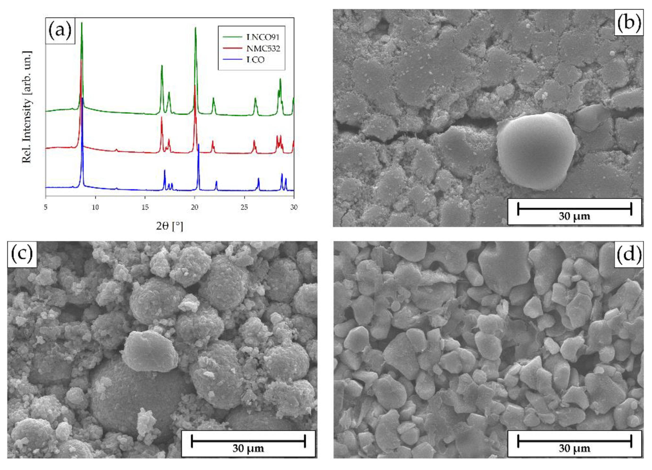
XRPD analyses of LNCO91 (Figure 1a, green), NMC532 (Figure 1a, red) and LCO (Figure 1a, blue) confirmed the crystal structure of the CAMs, which crystallize with a trigonal lattice, space group R-3m (166) and lattice parameters: #1) a=2.8443 Å, c=14.0679 Å for LNCO91; #2) a=2.8654 Å and c=14.2868 Å for NMC532; #3) and a=2.8175 Å and c=14.0802 Å for LCO. The slight differences in 2θ position of the peaks and their intensity were due to the small differences in the size of the cell and in the scattering factor of the three transition metals. All of three structures were consistent with the data widely reported in the literature [38,39,40].
As for the morphological analyses, SEM images of LNCO91 (Figure 1b) and NMC532 (Figure 1c) showed a dense packing of small CAM crystal forming large grains (about 5-50 μm diameter) surrounded by smaller Carbon particles (about 1-3 μm diameter) and held together by the polymeric binder (i.e. Polyvinylidene Fluoride, PVDF); LCO (Figure 1d) was composed by bigger and more regular crystals (about 3-20 μm diameter) than those of LNCO91 and NMC532.
Figure 1.
(a) XRD pattern of LNCO91 (green), NMC532 (red) and LCO (blue); Secondary Electrons (SE) 2000x SEM images of (b) LNCO91, (c) NMC532 and (d) LCO.
Figure 1.
(a) XRD pattern of LNCO91 (green), NMC532 (red) and LCO (blue); Secondary Electrons (SE) 2000x SEM images of (b) LNCO91, (c) NMC532 and (d) LCO.
2.2. The Recycling Process
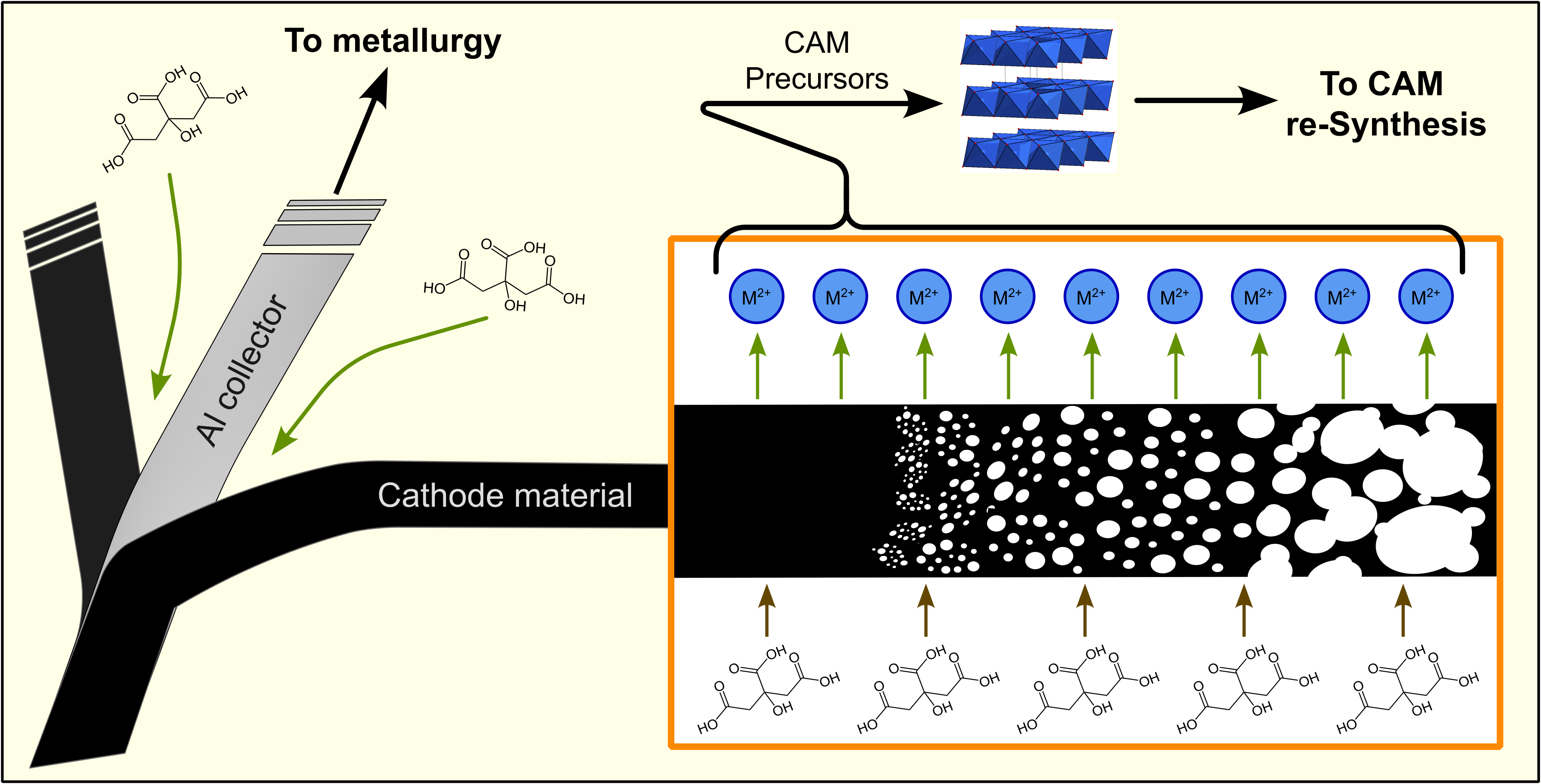
The whole cathode recycling process, as summarised in Figure 2, was based on a soft hydrometallurgical route adopting mild treatment conditions, such as natural organic acids, low temperature, short time and the potential to re-use the leaching solution in a multiple-step approach. It consisted of a simultaneous delamination/leaching process allowing the isolation of the current collector foil, the dissolution of the CAM and the separation of the cathode binder (PVDF). The leaching solution was then processed to precipitate the CAM precursors (p-CAM), necessary to resynthesise the starting cathode materials.
2.3. Delamination & Leaching
The disassembled cathodes were used to validate the proposed delamination/leaching process by means of treatment with citric acid (CA). A preliminary washing of the electrode was essential to remove the electrolyte salt (most commonly LiPF6) and its degradation products (mainly PF5, POF3). The reason is that many of these products react with water to form HF, a weak acid (pKa = 3.17 at 25°C) which is highly corrosive when in its undissociated form. As reported in literature, the corrosive power of HF is strongly dependent on the pH of the solution in which it is dissolved. At pH values below pKa, the hydrofluoric acid is completely undissociated [41]. Consequently, when the cathode is delaminated in a 1M CA-based solution, whose pH is ~ 1.6, without any washing step, the generated HF corrodes the aluminium current collector, which cannot be recovered anymore. Instead, a rapid washing of the electrode with distilled H2O allows LiPF6 and other fluorinated degradation products to be removed in a neutral environment, thus reducing the corrosive effect of HF, and preserving the aluminium collector during the subsequent delamination process (Figure 3).
Delamination allows the removal of Al current collector from the cathode active material (CAM). This step is crucial in cathode recycling for at least two reasons: Al is a valuable material which is usually metallurgically recycled; moreover, the aluminium separation avoids Al contaminations during the recovery of the CRMs from CAM or from the black mass, which are very difficult to isolate at a later stage. Manual delamination is time-consuming and currently requires an operator to scrape the cathode material from the current collector. Delamination in solution guarantees an efficient, automatable, and time-saving alternative to manual delamination, and may also be coupled with the subsequent leaching of the metals from the CAM, as described in the present work.
Delamination by means of agents (e.g., CA) that simultaneously leach the CAM metal ions can also offer several advantages in terms of process optimization. However, leaching of the metals from the cathode with a plain CA solution leads to unsatisfactory yields (around 60%); therefore, a reductant is needed to enhance the total rate of extraction. For this reason, several reductants have been proposed during these last years (H2O2, Cu, Glucose, Ascorbic Acid) to leach metal ions from various batteries (Li-ion, alkaline and zinc–carbon battery) and printed circuit boards (PCBs) [42,43,44,45,46]. Here, H2O2 was used, allowing very high leaching yields exceeding 95%.
More specifically, all the disassembled cathodes were treated in a 1M CA solution with 0.5wt.% H2O2 to detach the cathode layer from the Al current collector and allow the dissolution of the CAMs. Each current collector was easily recovered, washed and weighed to determine the fractions of Al on the total cathode, which were: #1) 6.2wt.% (for LNCO91); #2) 5.9wt.% (for NMC532); and #3) 9.0wt.% (for LCO).
2.4. PVDF+C Mixture
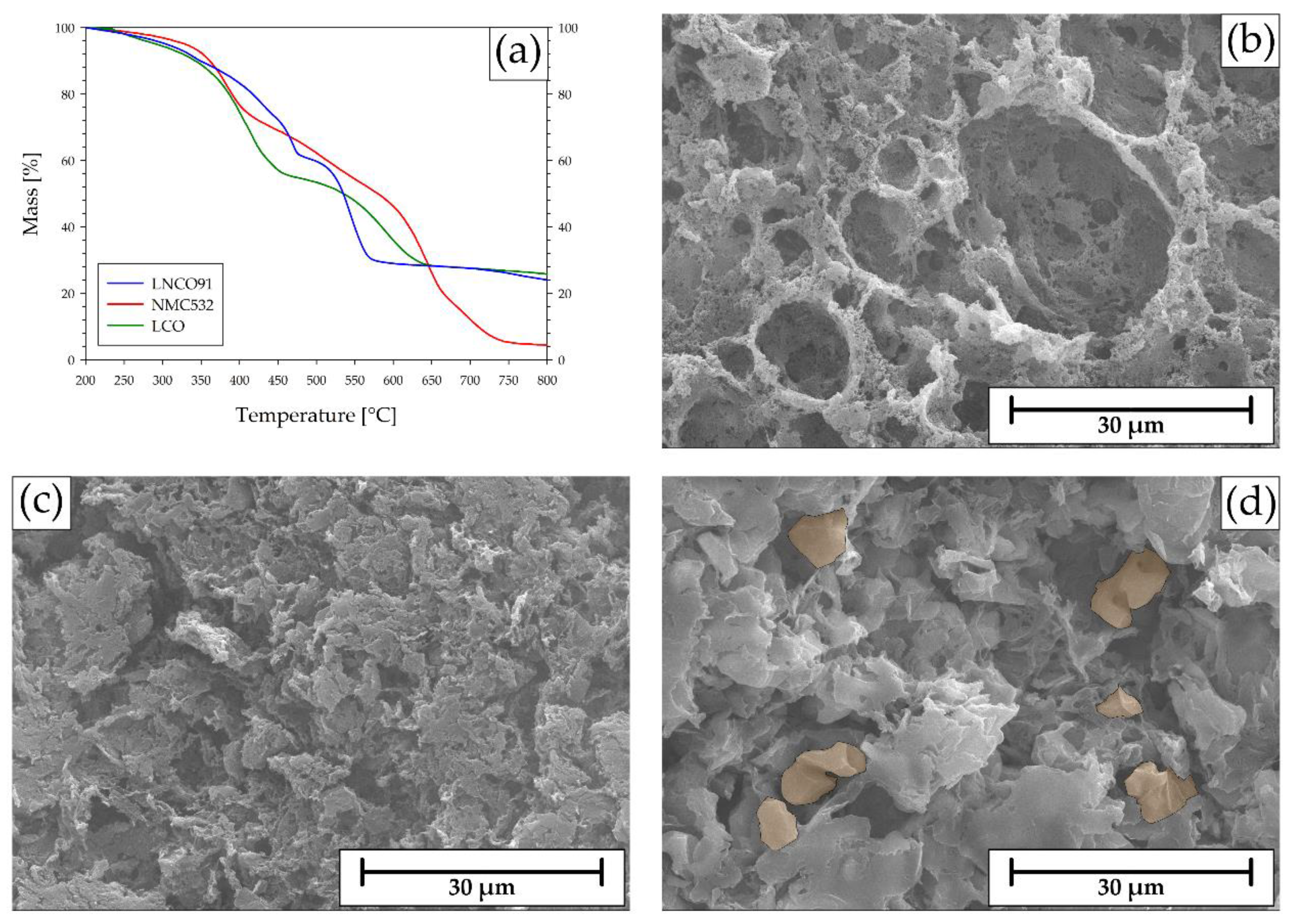
After the recovery of the current collector, each system was left stirring to achieve a complete leaching of the transition metal ions from the CAM. The results of this step were dark solutions (whose colours depended on the leached cathode) with black solid residue, composed by a mixture of PVDF and the Carbon conducting filler. The TGA analyses conducted in air on the black residues from the three cells (Figure 4a) showed different temperatures at which the binder decomposed and the carbon oxidized. In the specific case of LNCO91 and LCO, thermogravimetry allowed a good estimation of the PVDF/C ratio within the residue, which were about 1.1 and 1.6, respectively, while the estimation for the residue obtained from NMC532 was harder due to the overlapping of the mass loss steps (roughly 0.5). However, the PVDF+C mixtures were still contaminated by undissolved CAM, depending on the kind of cathode, namely about 25wt.% for LNCO91 and LCO and only 4% in case of NMC532. These results were used to determine the efficiency of the leaching process (L.E.) with the following equation:
where is the cathode mass, is the mass of the recovered Al current collector, is the mass of the recovered PVDF+C mixture and is the unleached CAM fraction in the mixture given by the TGA curve. The calculated leaching efficiency for LNCO91, NMC532 and LCO were 97.1%, 99.3%, and 95.8%, respectively.
The presence of undissolved CAM in the fraction of separated binder was also proved by the SEM analyses carried out on the PVDF+C composites (Figure 4b, c, d). In the specific residue obtained for example in case of LCO treatment (cell #3), large crystals of undissolved CAM were clearly evident and distributed along the porous polymeric network.
Figure 4.
(a) TGA curves of PVDF+C mixtures recovered from LNCO91 (blue), NMC532 (red) and LCO (green); SEM images of PVDF+C residues from: (b) LNCO91; (c) NMC532; (d) LCO (CAM crystals highlighted).
Figure 4.
(a) TGA curves of PVDF+C mixtures recovered from LNCO91 (blue), NMC532 (red) and LCO (green); SEM images of PVDF+C residues from: (b) LNCO91; (c) NMC532; (d) LCO (CAM crystals highlighted).
2.5. Precipitation of the CAM Precursors
Each solution containing the CAM leached was treated with Dihydrate Oxalic Acid (OA) to precipitate the transition metal ions as oxalate dihydrate from the corresponding cathode (Figure 5a, b, c). The Oxalates were produced with very high yields, all exceeding 85% (namely 88%, 88% and 92%, respectively). The elemental characterization of the products, performed by means of an ICP-OES and summarised in Figure 5, confirmed that the chemical composition well fits that one of the starting CAM, with the following formulas: (Ni0.90Co0.10)C2O4 ∙ 2H2O; (Ni0.49Mn0.31Co0.20)C2O4 ∙ 2H2O; (c) CoC2O4 ∙ 2H2O.
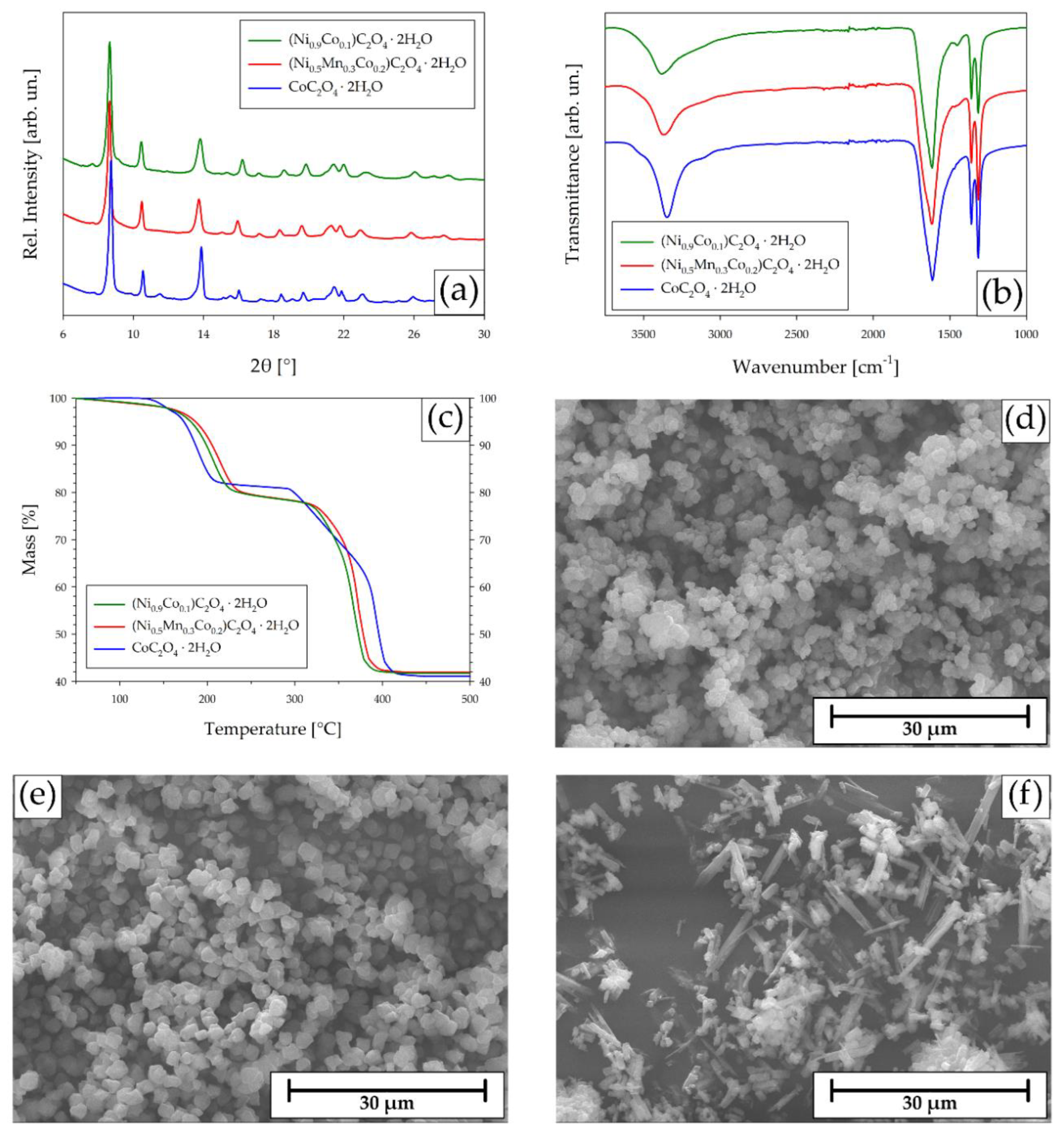
The XRD patterns of the oxalates (Figure 6a) confirm the crystallization with a monoclinic lattice, space group C2/c (15) reported in literature for CoC2O4 ∙ 2H2O [47]. The Rietveld refined structures, whose data are reported in Table 2, showed obvious similarities in terms of lattice parameters as well as XRD pattern (Figure 6a) since Ni2+, Mn2+, and Co2+ occupy the same crystallographic sites and have similar ionic radius and scattering factors.
FT-IR spectra of the oxalates (Figure 6b) overlapped: the broad band at around 3400 cm-1 was attributed to the presence of water of hydration; the intense peak at about 1600 cm-1 was attributed to the oxalate group and, in particular, was generated by the stretching of the C=O bond, which covered the C-C stretching signal of the same group; the two peaks at about 1350 cm-1 were due to the symmetric stretching of the O-C=O group.
A TGA analysis in nitrogen atmosphere was performed on the oxalates (Figure 6c) to determine the hydration state of the compounds. All the products showed the same thermal degradation behaviour, with two main losses of mass. The first one of about 20wt.% between 100°C and 250°C was attributed to the loss of two water molecules (in agreement with the nominal composition). The second one of about 40wt.% between 250°C and 450°C was actually a two-step mass loss, the first compatible with the release of one molecule of CO (accounting for 15wt.% of the total weight) and the second involving the loss of one molecule of CO2 (25wt.%). Given the general formula TC2O4 ∙ 2H2O (where, T is Ni0.9Co0.1, Ni0.5Mn0.3Co0.2 and Co for LNCO91, NMC532 and LCO, respectively), the complete thermal degradation process in nitrogen atmosphere may be described as:
As evident from the SEM analyses, the three recovered oxalates showed different morphologies. In more details, (Ni0.90Co0.10)C2O4 ∙ 2H2O (Figure 6d) and (Ni0.51Mn0.29Co0.2)C2O4 ∙ 2H2O (Figure 6e) were composed by several monodispersed 1-2 μm crystals with sphere-like shape. Instead, CoC2O4 ∙ 2H2O (Figure 6f) was formed by several agglomerates of rod-like grains with different lengths.
Figure 6.
Results of the analyses conducted on (Ni0.9Co0.1)C2O4∙2H2O (blue), (Ni0.5Mn0.3Co0.2)C2O4∙2H2O (red) and CoC2O4∙2H2O (black): (a) XRD patterns; (b) FT-IR spectra; (c) TGA curves; SE SEM 2000x images of (d) (Ni0.9Co0.1)C2O4∙2H2O, (e) (Ni0.5Mn0.3Co0.2)C2O4∙2H2O and (f) CoC2O4∙2H2O.
Figure 6.
Results of the analyses conducted on (Ni0.9Co0.1)C2O4∙2H2O (blue), (Ni0.5Mn0.3Co0.2)C2O4∙2H2O (red) and CoC2O4∙2H2O (black): (a) XRD patterns; (b) FT-IR spectra; (c) TGA curves; SE SEM 2000x images of (d) (Ni0.9Co0.1)C2O4∙2H2O, (e) (Ni0.5Mn0.3Co0.2)C2O4∙2H2O and (f) CoC2O4∙2H2O.
The TMs oxalates dihydrate were treated with NaOH to convert them to the corresponding hydroxide (Figure 7a, b, c) which are usually employed as industrial precursors for the synthesis of the pristine CAM. The proper identification of the resulting products was quite complex. While the hydroxide obtained from LNCO91 has a vibrant green colour typical of Ni(OH)2 (Figure 7a), the colour of the hydroxides from NMC532 (Figure 7b) and from LCO (Figure 7c) did not match the colours of the expected corresponding hydroxides of Ni, Mn or Co or a mixture of these. In case of Ni/Mn/Co mixed system (Figure 6b), a dark brown colour dominates, likely related to the formation of a mixture of Mn(OH)3 (dark brown) and MnO(OH) (black). Concerning the Co-based matrix, the resulting colour was related to the coexistence of the two Co(OH)2 phases: α-Co(OH)2, a rather unstable compound formed when Co(OH)2 is precipitated in a solution containing other anions, and the more stable β-Co(OH)2 that the α-phase is converted to, upon ageing (Figure 7c).
However, as for the oxalates, the compositional ratio among the transition metals well fitted the stoichiometry of the pristine CAMs (Table 3) which is then preserved throughout the whole recovery process.
The XRD patterns of the CAMs precursors are reported in Figure 8a. As evident, a proper interpretation was a hard task due to the presence of very broadened peaks. The poor quality of the patterns, especially those of (Ni0.90Co0.10)(OH)2 and (Ni0.51Mn0.29Co0.20)(OH)2, might be due to: (i) the co-existence of two deeply related structures for nickel(II) hydroxide, α-Ni(OH)2 ∙ xH2O (0.41 < x < 0.7) with space group P1m (162), and β-Ni(OH)2 with space group Pm1 (164) [48]; (ii) the presence of disorder-inducing defects in the crystal structures, such as stacking faults, from which a structure such as Ni(OH)2 suffers when precipitated at room temperature [49] and (iii) the partial dehydration and oxidation of the hydroxides of Ni, Mn and Co that lead to mixtures of oxyhydroxide with different stoichiometry. Apart from these issues, it is possible to consider a unique generic β-T(OH)2 structure with spacegroup Pm1 (164), where T represents the different transition metal fractions in the isolated hydroxides (namely, Ni0.90Co0.10, Ni0.51Mn0.29Co0.20 and Co). The patterns of (Ni0.90Co0.10)(OH)2 and (Ni0.51Mn0.29Co0.20)(OH)2 showed peaks attributable to the aforementioned structure with several signals matching those of β-Ni(OH)2 (since Ni was the most abundant metal in the structure), whereas in the case of Co(OH)2 (T = Co) the peaks could be ascribed exclusively to β-Co(OH)2.
TGA analyses in air were conducted to establish the state of hydration of the obtained hydroxides (Figure 8b). The following preliminary consideration on the thermal degradation of each TM hydroxide, namely Ni(OH)2, Mn(OH)2 and Co(OH)2, should be done. Ni(OH)2 undergoes a simple degradation process based on the elimination of one water molecule to form NiO between 248°C and 340°C [50]. Mn(OH)2 oxidizes easily in air at room temperature to form Mn(OH)3 which loses one molecule of water spontaneously to form MnOOH; this oxyhydroxide dehydrates between 220°C and 500°C to form Mn2O3 and, finally, oxidizes to MnO2 between 550°C and 950°C [51]. Co(OH)2 degradation involves the partial oxidation of Co2+ to Co3+ and the dehydroxylation of the compound at about 110°C, forming CoOOH; this oxyhydroxide undergoes a final dehydration between 150°C and 220°C to form the mixed oxide Co3O4 (CoO∙Co2O3) [52]. Above 800°C, the Co3+ part of Co3O4 is reduced to Co2+, giving CoO as a product and releasing oxygen.
In case of the precursor of LCO (namely Co(OH)2, blue curve in Figure 8b), the thermogram showed one thermal step describing the following decomposition process:
6 Co(OH)2 + O2 → 2 Co3O4 + 6 H2O
According to this reaction, the total calculated loss of mass is 14.0%, which is in line with the experimental 14.2% loss measured between 100°C and 300°C for Co(OH)2. Above 800°C, the evolution of O2 from the reduction of Co3+ to Co2+ corresponds to a calculated loss of mass of 5.7% which, again, is coherent with the second experimental loss of 5.9% experimentally measured.
The thermal decomposition processes of Ni0.90Co0.10(OH)2 (green curve in Figure 8b) and Ni0.51Mn0.29Co0.20(OH)2 (red curve in Figure 8b) could be similarly rationalised as in the following. Both the precursors lost water up to 350-400°C to likely form the relative mixtures of relevant TM oxide (NiO and CoO in the first case, and NiO, Mn2O3 and CoO in the second one). Calculated residual mass after elimination of water from Ni0.90Co0.10(OH)2 and Ni0.51Mn0.29Co0.20(OH)2 are, respectively, 81.2% and 81.6% which are in very good agreement with the losses measured via TGA analyses (80.4% and 81.5%, respectively). In conclusion these results suggest that the hydroxides precursors were fully hydroxylated, in agreement with the obtained complex XRD patterns.
Figure 8.
(a) XRD patterns of (Ni0.90Co0.1)(OH)2, (Ni0.51Mn0.29Co0.20)(OH)2 and Co(OH)2 (peaks of the references - Ni(OH)2 and Co(OH)2 - are reported in green and blue); (b) TGA analyses of (Ni0.90Co0.1)(OH)2 (green), (Ni0.51Mn0.29Co0.20)(OH)2 (red) and Co(OH)2 (blue); SEM images showing the morphologies of (c) (Ni0.90Co0.1)(OH)2, (d) (Ni0.51Mn0.29Co0.20)(OH)2 and (e) Co(OH)2.
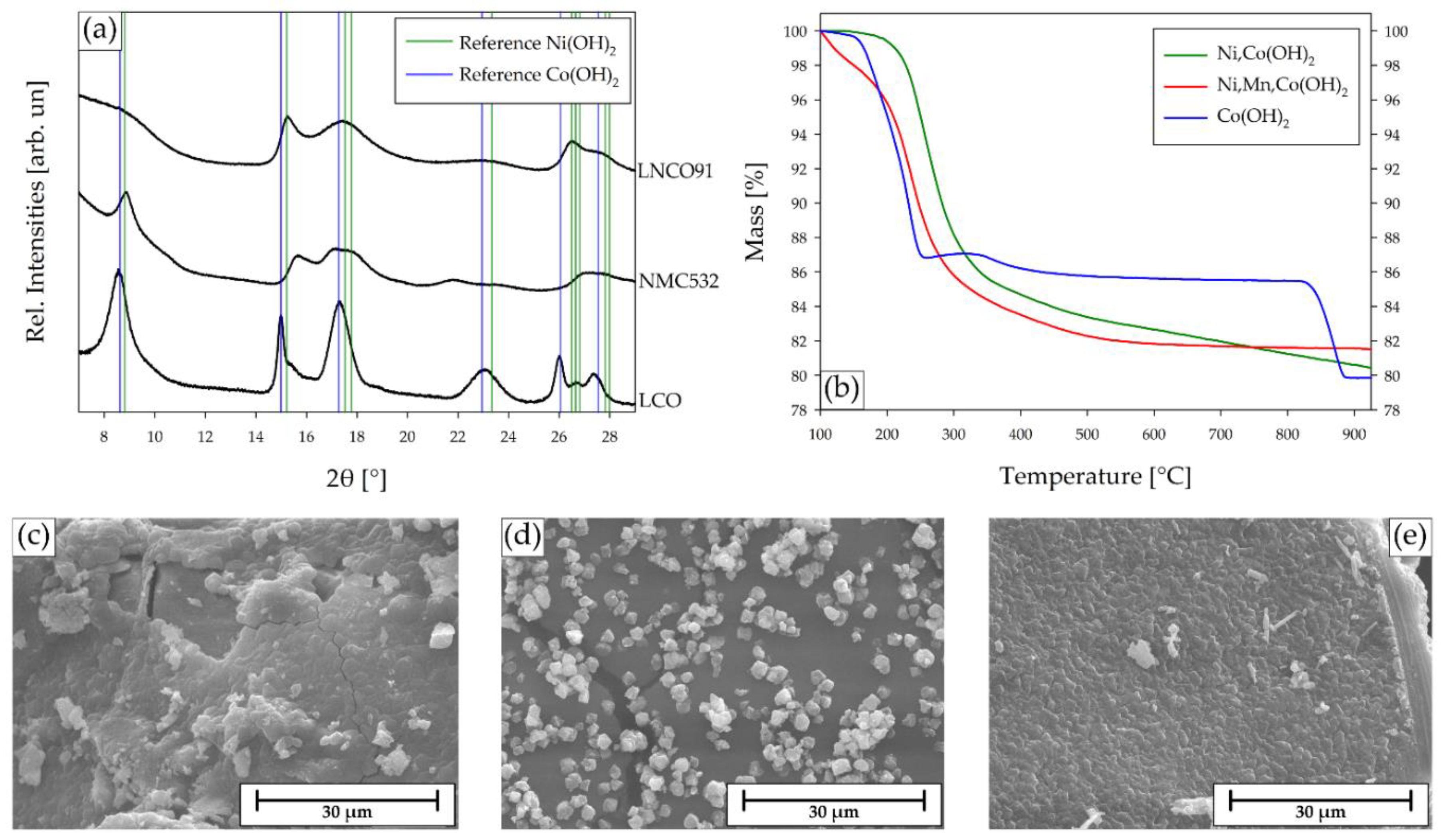
SEM images of the CAM precursors showed different morphologies. (Ni0.90Co0.10)(OH)2 (Figure 8c) and Co(OH)2 (Figure 8e) were composed by a densely packed structure of crystals, whereas (Ni0.51Mn0.29Co0.2)(OH)2 (Figure 8d) morphology resembled that of the corresponding oxalate, (Ni0.49Mn0.31Co0.20)C2O4 ∙ 2H2O (Figure 8c), showing several single grains of about 1 μm side.
2.6. Resynthesis of the NMC532 CAM from the Recovered Precursors
As an example of recycling loop, the (Ni0.51Mn0.29Co0.2)(OH)2 obtained in the previous step was used to resynthesise the CAM NMC532 by means of solid-state reaction with Li2CO3 as a Li source, used in proper excess to compensate eventual Li losses (ratio Li/metals was 1.2:1). The elemental analyses with ICP-OES confirmed the Ni/Mn/Co ratio of 5:3:2 and the correct Li stoichiometry, resulting in the global formula LiNi0.5Mn0.3Co0.2O2.
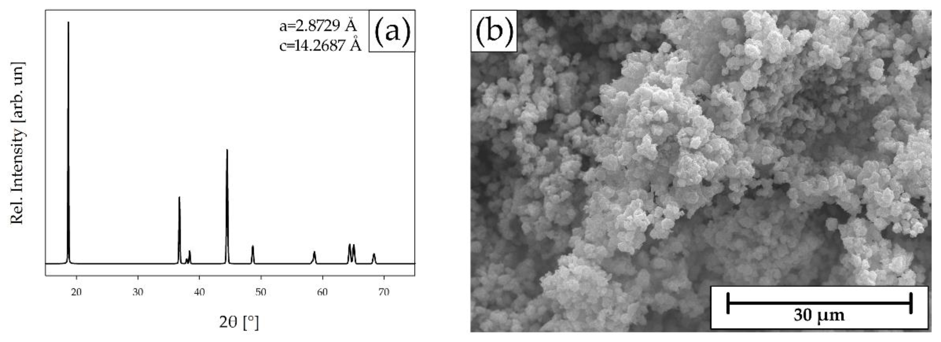
The XRD analyses (Figure 9a) on the sample confirmed the layered structure of NMC532, trigonal with space group Rm (166). The Rietveld-refined lattice parameters of the resynthesized NMC532 (a=2.8729 Å and c=14.2687 Å) were in very good agreement with those reported in the literature and used as a reference (a=2.8775 Å and c=14.2696 Å) [39].
The SEM image of the resynthesized NMC532 (Figure 9b) showed a homogeneous morphology composed by agglomerations of single grains with size lower than 5 μm.
Figure 9.
(a) XRD pattern and Rietveld-refined parameters of the resynthesized NMC532; (b) SE SEM images showing the morphology of the resynthesized NMC532.
Figure 9.
(a) XRD pattern and Rietveld-refined parameters of the resynthesized NMC532; (b) SE SEM images showing the morphology of the resynthesized NMC532.
3. Materials & Methods
3.1. Deactivation & Disassembling
Three different EoL 18650-type Li-ion cells (LNCO91, NMC532 and LCO) were discharged in a 5wt.% solution of NaNO2, which has already proved to be the best compromise in terms of time and efficiency of discharge, with low to no corrosion of the external shell [37]; corrosion of the outer shell can cause its breaking, leading the salt-saturated solution to infiltrate inside the cell. The discharged cells were then opened by breaking the outer steel casing, all the components were unrolled and easily manually separated without any breakage or loss of materials into the couple of electrodes and two layers of separator. The cathodes were washed and characterized by means of SEM, ICP-OES, TGA and XRPD analyses and, finally, processed as follows.
3.2. Recycling Process
A piece of cathode (2-3 g) was immersed in 100 mL of a 20wt.% CA + 0.5wt.% H2O2 solution. The system was heated to 50°C and left slowly stirring until the cathode material detaches from the Al current collector, which was manually recovered. The system was left stirring for another 1h to let the CAM dissolve; the solution was then gravity filtered on filter paper to recover the undissolved fractions composed by binder and carbon, which were washed with water and characterised.
The leaching solution was treated with 1.2 equivalents of OA, slowly added as a 10wt% solution at 50°C until the solution becomes colourless, and the corresponding transition metals oxalates precipitate; the system is, then, left stirring for 1h before filtering the products, which were washed and characterized.
The transition metals oxalates dihydrate (1 g) were treated with 2.5 equivalents of NaOH dissolved in 40 mL of distilled water; the system was left stirring for 1h at room temperature until the complete formation of the hydroxides, which were recovered by vacuum filtration, washed, and characterized.
The (Ni0.51Mn0.29Co0.20)(OH)2 obtained from NMC532 was used to resynthesise new NMC532 CAM. A batch of hydroxide (500 mg) was mixed with 0.6 equivalents of Li2CO3 to have a final Li/metals ratio of 1.2, pressed into a pellet and thermally treated at 900°C in air for 8h.
3.3. Characterization
Morphological analyses on cathodes and products were conducted with a SEC SNE-4500M Plus Scanning Electron Microscope (SEM) in high vacuum, with an accelerating voltage of 20 kV.
Crystal structures of cathodes, oxalates and hydroxides were analysed using a Bruker D8 ADVANCE A25 X-Ray Powder Diffractometer with Mo Kα radiation, equipped with an Eiger 250K detector. Analyses were conducted with a Bragg-Brentano geometry in the 2θ range 4-40° with 0.005° step size and 2s time steps. Crystal structure of the resynthesized NMC532 were analysed with a Bruker D6 X-Ray Powder Diffractometer with Cu Kα radiation. Analyses were conducted with a Bragg-Brentano geometry in the 2θ range 13-80° with 0.03° step size and 2s time steps. Lattice parameters of the crystal structures were Rietveld-refined using the program FullProf implemented in the software Match! – Version 3.15.
Compositional analyses were conducted with a Perkin-Elmer AvioTM 220 Max Inductively Coupled Plasma Optical Emission Spectroscope (ICP-OES). Five standard solutions were used to calibrate the instrument (0.3 – 0.6 – 2.0 – 5.0 – 9.0 ppm) and Li, Ni, Mn, and Co emissions were read at, respectively, 670.784 nm, 231.604 nm, 257.610 nm, and 228.616 nm. Solid samples were digested in 68wt.% HNO3 and diluted with distilled water to a concentration between the extremes of the calibration curve; liquid samples were directly diluted with distilled water.
Thermogravimetric analyses were conducted using a Perkin-Elmer Simultaneous Thermal Analyzer 8000 (STA) in air atmosphere, from 30°C to 1000°C with a 10°C/min rate under air flow (50 mL min-1 for PVDF+C mixtures) or N2 flow (50 mL min-1 for metal oxalates).
Infrared spectroscopic analyses were conducted using a Perkin-Elmer Spectrum Two Fourier Transform Infrared Spectrometer (FT-IR) equipped with ATR crystal. Analyses were conducted by registering and co-adding 4 scans at room temperature in the range 400-4000 cm-1 at 4 cm-1 resolution.
4. Conclusions
In this study, a sustainable recycling process for EoL Li-ion batteries based of a soft hydrometallurgical approach is proposed and discussed for different chemistries, namely LNCO91, NMC532 and LCO. More specifically, a one-step delamination/leaching treatment was carried to simultaneously recover the cathode current collector (Al) as undamaged metallic foil, to separate the polymeric binder (PVDF) ready to be used and to extract the transition metal ions of the cathode active materials. To this aim, a natural organic acid was used, namely citric acid, instead of mineral inorganic acids usually employed in the state-of-the-art hydrometallurgy. High leaching yields, exceeding 88%, were obtained by means of mild conditions, namely short time (1 hour) and low temperature (50°C), for Li Ni, Co and Mn. The transition metal ions were quantitatively precipitated as oxalates and easily converted to the corresponding hydroxides as precursors of the cathode active materials, preserving the same proper stoichiometry of the corresponding CAM. In the case of NMC, the obtained precursors were finally used to resynthesize the fresh CAM, thus closing the recycling loop.
The proposed single delamination/leaching process has the potential to speed up the battery recycling processes with promising improvements in terms of sustainability aspects (e.g. use of water, energy consumption, environmental impact of the reactants).
Author Contributions
Conceptualization, F.D.A., A.R. and P.C.; Methodology, P.C. and D.C.; Investigation, P.C. and D.C..; Data Curation, P.C..; Writing – Original Draft Preparation, P.C..; Writing – Review & Editing, E.Q.; Supervision, F.D.A., A.R and E.Q.; Project Administration, E.Q.; Funding Acquisition, E.Q.
Funding
The authors acknowledge funding from the European Union’s Horizon Europe research and innovation program under Grant Agreements Ns° 101137745 (RENOVATE) and 101104022 (BATTERY2030 CSA3).
Acknowledgments
Additionally, EQ thanks Regione Lombardia (IT) for the economic support in the context of the institutional agreement in the establishment of EcoCirc facilities for a “System integrator towards circular economy”.
Conflicts of Interests
The authors declare no conflicts of interests.
References
- Zion Market Research. Lithium-Ion Battery Market Size, Share by Type, by Industry, and By Region - Global And Regional Industry Overview, Market Intelligence, Comprehensive Analysis, Historical Data, And Forecasts 2022-2028; ZMR-2165; 2022.
- Facts & Factors. Lithium-Ion Battery Market Size, Share, Growth Analysis Report by Application, by Type, by Capacity, and by Region - Global and Regional Industry Insights, Overview, Comprehensive Analysis, Trends, Statistical Research, Market Intelligence, Historical Data and Forecast 2022-2030; FAF-2228; 2022.
- Grand View Research. Lithium-Ion Battery Market Size, Share & Trends Analysis Report by Product, by Application, by Region, and Segment Forecasts, 2024-2030; GVR-1-68038-601-1; 2024. grandviewresearch.com/industry-analysis/lithium-ion-battery-market.
- Global Market Insights. Lithium-Ion Battery Market Size - by Chemistry, Component, Application & Forecast, 2024-2032; GMI1135; 2024. gminsights.com/industry-analysis/lithium-ion-battery-market.
- European Parliament; Council of the European Union. Regulation (EU) 2024/1252 of the European Parliament and of the Council of 11 April 2024 Establishing a Framework for Ensuring a Secure and Sustainable Supply of Critical Raw Materials and Amending Regulations (EU) No 168/2013, (EU) 2018/858, (EU) 2018/1724 and (EU) 2019/1020. Official Journal of the European Union. May 3, 2024. http://data.europa.eu/eli/reg/2024/1252/oj (accessed 2024-05-29).
- Mrozik, W.; Rajaeifar, M. A.; Heidrich, O.; Christensen, P. Environmental Impacts, Pollution Sources and Pathways of Spent Lithium-Ion Batteries. Energy Environ. Sci. 2021, 14, 6099–6121. [Google Scholar] [CrossRef]
- Harper, G. D. J.; Kendrick, E.; Anderson, P. A.; Mrozik, W.; Christensen, P.; Lambert, S.; Greenwood, D.; Das, P. K.; Ahmeid, M.; Milojevic, Z.; Du, W.; Brett, D. J. L.; Shearing, P. R.; Rastegarpanah, A.; Stolkin, R.; Sommerville, R.; Zorin, A.; Durham, J. L.; Abbott, A. P.; Thompson, D.; Browning, N. D.; Mehdi, B. L.; Bahri, M.; Schanider-Tontini, F.; Nicholls, D.; Stallmeister, C.; Friedrich, B.; Sommerfeld, M.; Driscoll, L. L.; Jarvis, A.; Giles, E. C.; Slater, P. R.; Echavarri-Bravo, V.; Maddalena, G.; Horsfall, L. E.; Gaines, L.; Dai, Q.; Jethwa, S. J.; Lipson, A. L.; Leeke, G. A.; Cowell, T.; Farthing, J. G.; Mariani, G.; Smith, A.; Iqbal, Z.; Golmohammadzadeh, R.; Sweeney, L.; Goodship, V.; Li, Z.; Edge, J.; Lander, L.; Nguyen, V. T.; Elliot, R. J. R.; Heidrich, O.; Slattery, M.; Reed, D.; Ahuja, J.; Cavoski, A.; Lee, R.; Driscoll, E.; Baker, J.; Littlewood, P.; Styles, I.; Mahanty, S.; Boons, F. Roadmap for a Sustainable Circular Economy in Lithium-Ion and Future Battery Technologies. J. Phys. Energy 2023, 5, 021501. [Google Scholar] [CrossRef]
- Zeng, X.; Li, J.; Liu, L. Solving Spent Lithium-Ion Battery Problems in China: Opportunities and Challenges. Renew. Sustain. Energy Rev. 2015, 52, 1759–1767. [Google Scholar] [CrossRef]
- Winslow, K. M.; Laux, S. J.; Townsend, T. G. A Review on the Growing Concern and Potential Management Strategies of Waste Lithium-Ion Batteries. Resour. Conserv. Recycl. 2018, 129, 263–277. [Google Scholar] [CrossRef]
- Ferrara, C.; Ruffo, R.; Quartarone, E.; Mustarelli, P. Circular Economy and the Fate of Lithium Batteries: Second Life and Recycling. Adv. Energy Sustain. Res. 2021, 2, 2100047. [Google Scholar] [CrossRef]
- Kim, S.; Bang, J.; Yoo, J.; Shin, Y.; Bae, J.; Jeong, J.; Kim, K.; Dong, P.; Kwon, K. A Comprehensive Review on the Pretreatment Process in Lithium-Ion Battery Recycling. J. Clean. Prod. 2021, 294, 126329. [Google Scholar] [CrossRef]
- Colledani, M.; Gentilini, L.; Mossali, E.; Picone, N. A Novel Mechanical Pre-Treatment Process-Chain for the Recycling of Li-Ion Batteries. CIRP Ann. 2023, 72, 17–20. [Google Scholar] [CrossRef]
- Woeste, R.; Drude, E.-S.; Vrucak, D.; Klöckner, K.; Rombach, E.; Letmathe, P.; Friedrich, B. A Techno-Economic Assessment of Two Recycling Processes for Black Mass from End-of-Life Lithium-Ion Batteries. Appl. Energy 2024, 361, 122921. [Google Scholar] [CrossRef]
- Thompson, D.; Hyde, C.; Hartley, J. M.; Abbott, A. P.; Anderson, P. A.; Harper, G. D. J. To Shred or Not to Shred: A Comparative Techno-Economic Assessment of Lithium Ion Battery Hydrometallurgical Recycling Retaining Value and Improving Circularity in LIB Supply Chains. Resour. Conserv. Recycl. 2021, 175, 105741. [Google Scholar] [CrossRef]
- Zha, Y.; Meng, Q.; Dong, P.; Zhang, Y. The Latest Research on the Pre-Treatment and Recovery Methods of Spent Lithium-Ion Battery Cathode Material. Ionics 2024, 30, 623–645. [Google Scholar] [CrossRef]
- He, L.-P.; Sun, S.-Y.; Song, X.-F.; Yu, J.-G. Recovery of Cathode Materials and Al from Spent Lithium-Ion Batteries by Ultrasonic Cleaning. Waste Manag. 2015, 46, 523–528. [Google Scholar] [CrossRef] [PubMed]
- Shaw-Stewart, J.; Alvarez-Reguera, A.; Greszta, A.; Marco, J.; Masood, M.; Sommerville, R.; Kendrick, E. Aqueous Solution Discharge of Cylindrical Lithium-Ion Cells. Sustain. Mater. Technol. 2019, 22, e00110. [Google Scholar] [CrossRef]
- Harper, G.; Sommerville, R.; Kendrick, E.; Driscoll, L.; Slater, P.; Stolkin, R.; Walton, A.; Christensen, P.; Heidrich, O.; Lambert, S.; Abbott, A.; Ryder, K.; Gaines, L.; Anderson, P. Recycling Lithium-Ion Batteries from Electric Vehicles. Nature 2019, 575, 75–86. [Google Scholar] [CrossRef] [PubMed]
- Hanisch, C.; Loellhoeffel, T.; Diekmann, J.; Markley, K. J.; Haselrieder, W.; Kwade, A. Recycling of Lithium-Ion Batteries: A Novel Method to Separate Coating and Foil of Electrodes. J. Clean. Prod. 2015, 108, 301–311. [Google Scholar] [CrossRef]
- He, L.-P.; Sun, S.-Y.; Song, X.-F.; Yu, J.-G. Leaching Process for Recovering Valuable Metals from the LiNi1/3Co1/3Mn1/3O2 Cathode of Lithium-Ion Batteries. Waste Manag. 2017, 64, 171–181. [Google Scholar] [CrossRef] [PubMed]
- Ji, Y.; Jafvert, C. T.; Zyaykina, N. N.; Zhao, F. Decomposition of PVDF to Delaminate Cathode Materials from End-of-Life Lithium-Ion Battery Cathodes. J. Clean. Prod. 2022, 367, 133112. [Google Scholar] [CrossRef]
- Bai, Y.; Muralidharan, N.; Li, J.; Essehli, R.; Belharouak, I. Sustainable Direct Recycling of Lithium-Ion Batteries via Solvent Recovery of Electrode Materials. ChemSusChem 2020, 13, 5664–5670. [Google Scholar] [CrossRef]
- Bai, Y.; Hawley, W. B.; Jafta, C. J.; Muralidharan, N.; Polzin, B. J.; Belharouak, I. Sustainable Recycling of Cathode Scraps via Cyrene-Based Separation. Sustain. Mater. Technol. 2020, 25, e00202. [Google Scholar] [CrossRef]
- Hansen, B. B.; Spittle, S.; Chen, B.; Poe, D.; Zhang, Y.; Klein, J. M.; Horton, A.; Adhikari, L.; Zelovich, T.; Doherty, B. W.; Gurkan, B.; Maginn, E. J.; Ragauskas, A.; Dadmun, M.; Zawodzinski, T. A.; Baker, G. A.; Tuckerman, M. E.; Savinell, R. F.; Sangoro, J. R. Deep Eutectic Solvents: A Review of Fundamentals and Applications. Chem. Rev. 2021, 121, 1232–1285. [Google Scholar] [CrossRef] [PubMed]
- Wang, M.; Tan, Q.; Liu, L.; Li, J. A Low-Toxicity and High-Efficiency Deep Eutectic Solvent for the Separation of Aluminum Foil and Cathode Materials from Spent Lithium-Ion Batteries. J. Hazard. Mater. 2019, 380, 120846. [Google Scholar] [CrossRef] [PubMed]
- Ji, Y.; Jafvert, C. T.; Zhao, F. Degradation of Cathode in Air and Its Influences on Direct Recycling. J. Clean. Prod. 2024, 436, 140597. [Google Scholar] [CrossRef]
- European Commission. Directive 2008/98/EC of the European Parliament and of the Council of 19 November 2008 on Waste and Repealing Certain Directives, 2008.
- European Commission. Directive (EU) 2018/851 of the European Parliament and of the Council of 30 May 2018 Amending Directive 2008/98/EC on Waste, 2018.
- Makuza, B.; Tian, Q.; Guo, X.; Chattopadhyay, K.; Yu, D. Pyrometallurgical Options for Recycling Spent Lithium-Ion Batteries: A Comprehensive Review. J. Power Sources 2021, 491, 229622. [Google Scholar] [CrossRef]
- Jain, S.; Hoseyni, S. M.; Cordiner, J. Safety Considerations for Hydrometallurgical Metal Recovery from Lithium-ion Batteries. Process Saf. Prog. 2024, 43, 1–8. [Google Scholar] [CrossRef]
- Golmohammadzadeh, R.; Faraji, F.; Rashchi, F. Recovery of Lithium and Cobalt from Spent Lithium Ion Batteries (LIBs) Using Organic Acids as Leaching Reagents: A Review. Resour. Conserv. Recycl. 2018, 136, 418–435. [Google Scholar] [CrossRef]
- Larba, R.; Boukerche, I.; Alane, N.; Habbache, N.; Djerad, S.; Tifouti, L. Citric Acid as an Alternative Lixiviant for Zinc Oxide Dissolution. Hydrometallurgy 2013, 134–135, 117–123. [CrossRef]
- Li, L.; Dunn, J. B.; Zhang, X. X.; Gaines, L.; Chen, R. J.; Wu, F.; Amine, K. Recovery of Metals from Spent Lithium-Ion Batteries with Organic Acids as Leaching Reagents and Environmental Assessment. J. Power Sources 2013, 233, 180–189. [Google Scholar] [CrossRef]
- Musariri, B.; Akdogan, G.; Dorfling, C.; Bradshaw, S. Evaluating Organic Acids as Alternative Leaching Reagents for Metal Recovery from Lithium Ion Batteries. Miner. Eng. 2019, 137, 108–117. [Google Scholar] [CrossRef]
- Ku, H.; Jung, Y.; Jo, M.; Park, S.; Kim, S.; Yang, D.; Rhee, K.; An, E.-M.; Sohn, J.; Kwon, K. Recycling of Spent Lithium-Ion Battery Cathode Materials by Ammoniacal Leaching. J. Hazard. Mater. 2016, 313, 138–146. [Google Scholar] [CrossRef]
- Roy, J. J.; Cao, B.; Madhavi, S. A Review on the Recycling of Spent Lithium-Ion Batteries (LIBs) by the Bioleaching Approach. Chemosphere 2021, 282, 130944. [Google Scholar] [CrossRef] [PubMed]
- Cattaneo, P.; Callegari, D.; Merli, D.; Tealdi, C.; Vadivel, D.; Milanese, C.; Kapelyushko, V.; D’Aprile, F.; Quartarone, E. Sorting, Characterization, Environmentally Friendly Recycling, and Reuse of Components from End-of-Life 18650 Li Ion Batteries. Adv. Sustain. Syst. 2023, 7, 2300161. [Google Scholar] [CrossRef]
- Mukai, K.; Sugiyama, J.; Aoki, Y. Structural, Magnetic, and Electrochemical Studies on Lithium Insertion Materials LiNi1−xCoxO2 with 0≤x≤0. 25. J. Solid State Chem. 2010, 183(7), 1726–1732. [Google Scholar] [CrossRef]
- Zhu, H.; Xie, T.; Chen, Z.; Li, L.; Xu, M.; Wang, W.; Lai, Y.; Li, J. The Impact of Vanadium Substitution on the Structure and Electrochemical Performance of LiNi0. 5Co0.2Mn0.3O2. Electrochimica Acta 2014, 135, 77–85. [Google Scholar] [CrossRef]
- Gummow, R.; Liles, D.; Thackeray, M.; David, W. A Reinvestigation of the Structures of Lithium-Cobalt-Oxides with Neutron-Diffraction Data. Mater. Res. Bull. 1993, 28(11), 1177–1184. [Google Scholar] [CrossRef]
- Cattarin, S.; Guerriero, P.; Musiani, M.; Tuissi, A.; Vázquez-Gómez, L. Electrochemical Etching of NiTi Alloy in a Neutral Fluoride Solution. J. Electrochem. Soc. 2009, 156, C428. [Google Scholar] [CrossRef]
- Sayilgan, E.; Kukrer, T.; Yigit, N. O.; Civelekoglu, G.; Kitis, M. Acidic Leaching and Precipitation of Zinc and Manganese from Spent Battery Powders Using Various Reductants. J. Hazard. Mater. 2010, 173, 137–143. [Google Scholar] [CrossRef] [PubMed]
- Chen, X.; Zhou, T. Hydrometallurgical Process for the Recovery of Metal Values from Spent Lithium-Ion Batteries in Citric Acid Media. Waste Manag. Res. J. Sustain. Circ. Econ. 2014, 32, 1083–1093. [Google Scholar] [CrossRef]
- Jadhav, U.; Su, C.; Hocheng, H. Leaching of Metals from Large Pieces of Printed Circuit Boards Using Citric Acid and Hydrogen Peroxide. Environ. Sci. Pollut. Res. 2016, 23, 24384–24392. [Google Scholar] [CrossRef]
- Meng, Q.; Zhang, Y.; Dong, P. Use of Glucose as Reductant to Recover Co from Spent Lithium Ions Batteries. Waste Manag. 2017, 64, 214–218. [Google Scholar] [CrossRef] [PubMed]
- Cerrillo-Gonzalez, M. D. M.; Paz-Garcia, J. M.; Muñoz-Espinosa, M.; Rodriguez-Maroto, J. M.; Villen-Guzman, M. Extraction and Selective Precipitation of Metal Ions from LiCoO2 Cathodes Using Citric Acid. J. Power Sources 2024, 592, 233870. [Google Scholar] [CrossRef]
- Deyrieux, R.; Berro, C.; Peneloux, A. Contribution a l’étude Des Oxalates de Certains Métaux Bivalents. III. Structure Cristalline Des Oxalates Dihydratés de Manganèse, de Cobalt, de Nickel et de Zinc. Polymorphisme Des Oxalates Dihydratés de Cobalt et de Nickel. Bull. Société Chim. Fr. 1973, 25–34.
- Hall, D. S.; Lockwood, D. J.; Bock, C.; MacDougall, B. R. Nickel Hydroxides and Related Materials: A Review of Their Structures, Synthesis and Properties. Proc. R. Soc. Math. Phys. Eng. Sci. 2015, 471, 20140792. [Google Scholar] [CrossRef]
- Delmas, C.; Tessier, C. Stacking Faults in the Structure of Nickel Hydroxide: A Rationale of Its High Electrochemical Activity. J. Mater. Chem. 1997, 7, 1439–1443. [Google Scholar] [CrossRef]
- Aghazadeh, M.; Ghaemi, M.; Sabour, B.; Dalvand, S. Electrochemical Preparation of Alpha-Ni(OH)2 Ultrafine Nanoparticles for High-Performance Supercapacitors. J. Solid State Electrochem. 2014, 18, 1569–1584. [Google Scholar] [CrossRef]
- Sato, M.; Matsuki, K.; Sugawara, M.; Endo, T. Pyrolysis of gamma-Manganese Hydroxide Oxide. Nippon Kagaku Kaishi 1973, 9, 1655–1660. [Google Scholar] [CrossRef]
- Ebrahimzade, H.; Khayati, G. R.; Schaffie, M. Preparation and Kinetic Modeling of Beta-Co(OH)2 Nanoplates Thermal Decomposition Obtained from Spent Li-Ion Batteries. Adv. Powder Technol. 2017, 28, 2779–2786. [Google Scholar] [CrossRef]
Figure 2.
Flow chart of the recycling process of the cathodes.
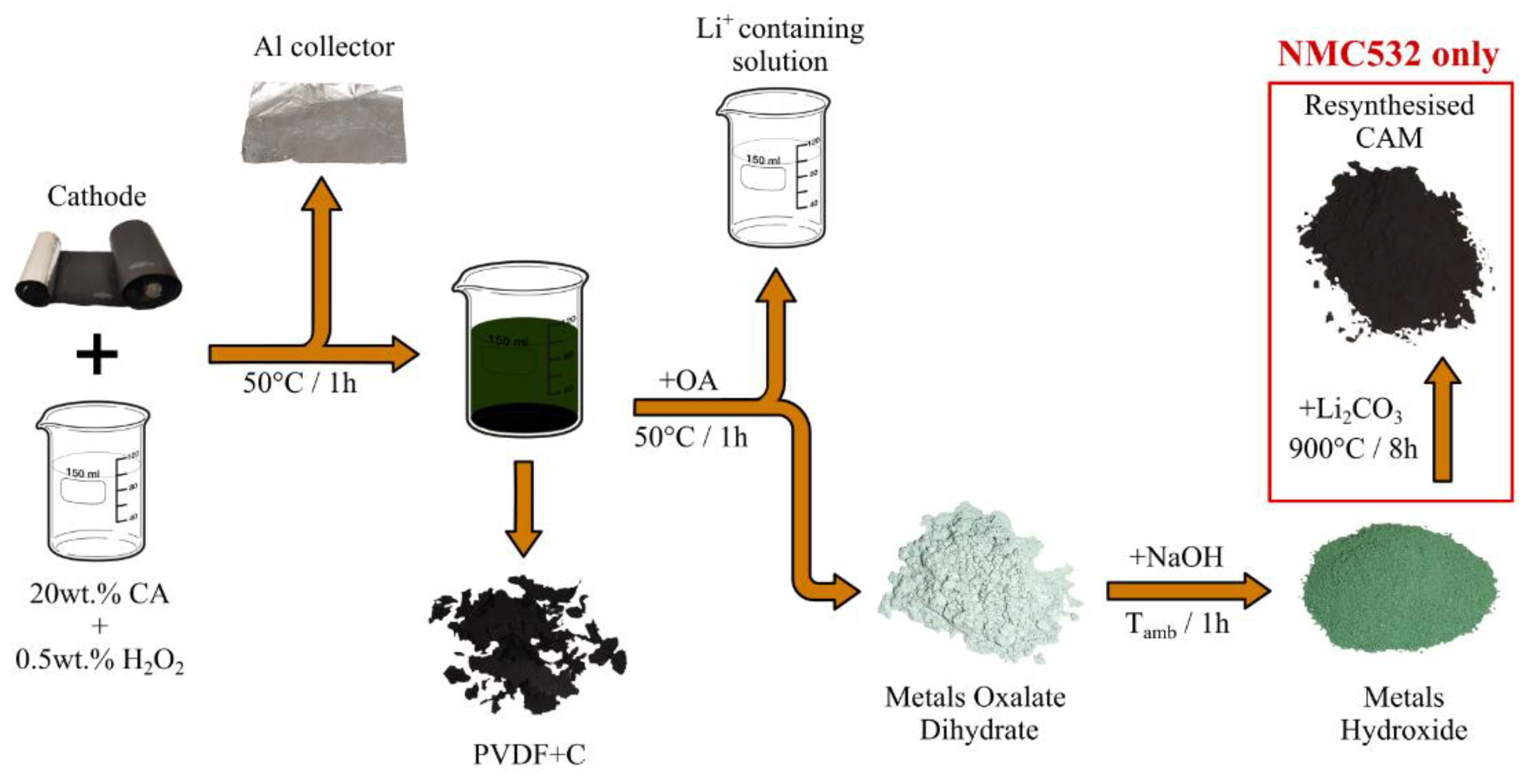
Figure 3.
(a) Collector from the washed cathode; (b) collector from the unwashed cathode.
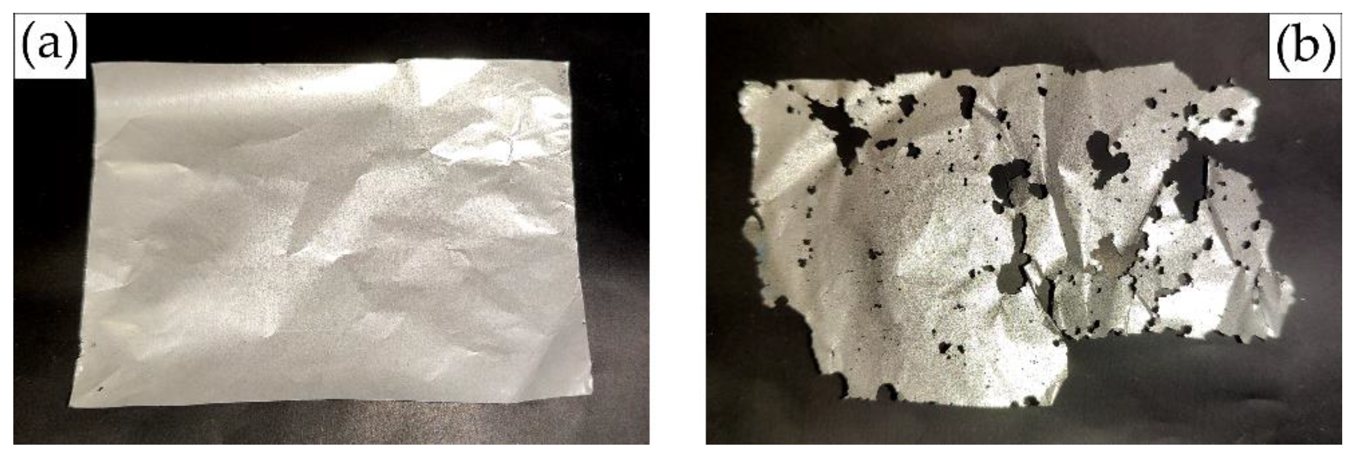
Figure 5.
(a) (Ni0.9Co0.1)C2O4∙2H2O from LNCO91; (b) (Ni0.5Mn0.3Co0.2)C2O4∙2H2O from NMC532; (c) CoC2O4∙2H2O from LCO.
Figure 5.
(a) (Ni0.9Co0.1)C2O4∙2H2O from LNCO91; (b) (Ni0.5Mn0.3Co0.2)C2O4∙2H2O from NMC532; (c) CoC2O4∙2H2O from LCO.
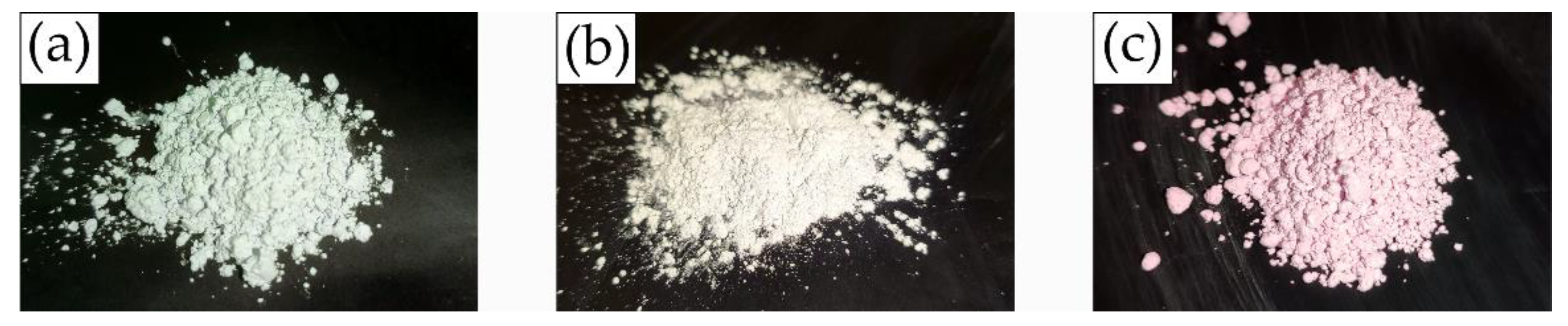
Figure 7.
(a) (Ni0.90Co0.10)(OH)2 from LNCO91; (b) (Ni0.51Mn0.29Co0.20)(OH)2 from NMC532; (c) Co(OH)2 from LCO.
Figure 7.
(a) (Ni0.90Co0.10)(OH)2 from LNCO91; (b) (Ni0.51Mn0.29Co0.20)(OH)2 from NMC532; (c) Co(OH)2 from LCO.
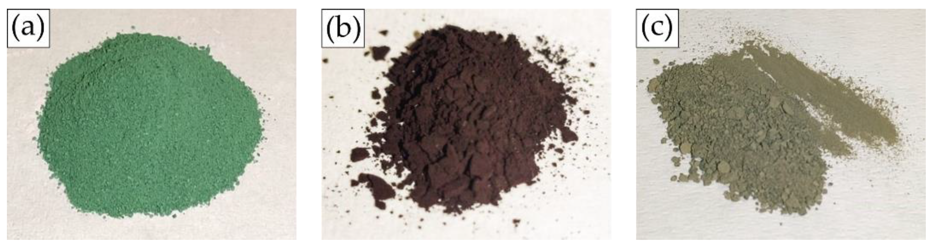

Table 1.
ICP data from the cathodes showing the ratio between Ni, Mn and Co and the ratio between Li and the transition metals.
Table 1.
ICP data from the cathodes showing the ratio between Ni, Mn and Co and the ratio between Li and the transition metals.
| Metal molar content | Sample name | ||||
| Ni | Mn | Co | Li | ||
| Cell #1 | 0.90 | 0.00 | 0.10 | 0.94 | LNCO91 |
| Cell #2 | 0.50 | 0.30 | 0.20 | 0.83 | NMC532 |
| Cell #3 | 0.00 | 0.00 | 1.00 | 0.94 | LCO |
Table 2.
Crystal systems, space-groups and lattice parameters for the oxalates obtained from the cathodes.
Table 2.
Crystal systems, space-groups and lattice parameters for the oxalates obtained from the cathodes.
| Sample | Crystal system | SG (no.) | a [Å] | b [Å] | c [Å] | β [°] |
| (Ni0.9Co0.1)C2O4 ∙ 2H2O | Monoclinic | C2/c (15) | 11.7927 | 5.3231 | 9.7454 | 126.8160 |
| (Ni0.5Mn0.3Co0.2)C2O4 ∙ 2H2O | Monoclinic | C2/c (15) | 11.9229 | 5.4360 | 9.8012 | 127.140 |
| CoC2O4 ∙ 2H2O | Monoclinic | C2/c (15) | 11.8516 | 5.4248 | 9.7568 | 126.933 |
Table 3.
Elemental composition of the products obtained from LNCO91, MNC532 and LCO.
| Starting CAM | Product | Element fractions | ||
| Ni | Mn | Co | ||
| LNCO91 | (Ni0.90Co0.10)C2O4 ∙ 2H2O | 0.90 | 0.00 | 0.10 |
| (Ni0.90Co0.10)(OH)2 | 0.90 | 0.00 | 0.10 | |
| NMC532 | (Ni0.49Mn0.31Co0.20)C2O4 ∙ 2H2O | 0.49 | 0.31 | 0.20 |
| (Ni0.51Mn0.29Co0.20)(OH)2 | 0.51 | 0.29 | 0.20 | |
| LCO | CoC2O4 ∙ 2H2O | 0.00 | 0.00 | 1.00 |
| Co(OH)2 | 0.00 | 0.00 | 1.00 | |
Disclaimer/Publisher’s Note: The statements, opinions and data contained in all publications are solely those of the individual author(s) and contributor(s) and not of MDPI and/or the editor(s). MDPI and/or the editor(s) disclaim responsibility for any injury to people or property resulting from any ideas, methods, instructions or products referred to in the content. |
© 2025 by the authors. Licensee MDPI, Basel, Switzerland. This article is an open access article distributed under the terms and conditions of the Creative Commons Attribution (CC BY) license (https://creativecommons.org/licenses/by/4.0/).
Copyright: This open access article is published under a Creative Commons CC BY 4.0 license, which permit the free download, distribution, and reuse, provided that the author and preprint are cited in any reuse.


