
Submitted:
24 June 2025
Posted:
25 June 2025
You are already at the latest version
Abstract
This research experimentally and numerically evaluates the effectiveness of viscoelastic (VE) and rotational friction (RF) dampers in enhancing the seismic performance of coupled shear wall (CSW) systems. The study consists of two phases: (1) element testing to characterize the hysteretic behavior and energy dissipation capacity of VE and RF dampers, and (2) shake table testing of a large-scale CSW structure equipped with these dampers under the white noise, sinusoidal and Kokuji wave. The experimental results are validated through numerical analysis using STERA 3D, a nonlinear finite element software, to simulate the dynamic response of the damped CSW system. Key performance indicators, including inter-story drift, base shear, and energy dissipation, are compared between experimental and numerical results, demonstrating strong correlation. The findings reveal that VE dampers effectively control high-frequency vibrations, while RF dampers provide stable energy dissipation across varying displacement amplitudes. The validated numerical model facilitates the optimization of damper configurations for performance-based seismic design. This study provides valuable insights into the selection and implementation of supplemental damping systems for CSW structures, contributing to improved seismic resilience in buildings.
Keywords:
Coupled shear wall
; viscoelastic damper
; rotational friction damper
; shake table test
; numerical validation
1. Introduction
The coupled shear wall system has been introduced due to its superior lateral stiffness compared to other lateral force-resisting systems [1]. The incorporation of high-stiffness structural members enhances the control of lateral forces acting on buildings, effectively minimizing lateral deformations. This characteristic is particularly crucial for high-rise buildings, where structural design is predominantly influenced by dynamic lateral loads. Coupling beams facilitate shear force transfer between shear walls, thereby enhancing energy dissipation. Consequently, coupled shear walls are regarded as an optimal solution for achieving the desired strength, stiffness, and ductility in structures [2]. However, inadequate design capacity or excessive lateral loading may lead to structural deterioration, including flexural failure at coupling beam joints and the base of structural walls. The degradation of lateral stiffness due to excessive damage further complicates the control of structural vibrations, posing significant challenges in maintaining the building's overall stability.
The VE damper represents a highly effective alternative for energy dissipation systems and has been widely utilized for wind and seismic protection of buildings for nearly five decades [3,4,5,6]. The implementation of VE dampers in coupled shear wall structures is particularly advantageous due to their dual function of enhancing stiffness and dissipating energy, thereby effectively mitigating drift and structural forces. The implementation of dampers as substitutes for structural elements, such as coupling beams or outriggers, ensures that no usable architectural space is compromised. Under lateral or in-plane torsional deformation of the building, the relative displacement be-tween walls induce differential vertical movement within the coupling elements, subjecting the VE material layers to shear deformation. This mechanism generates a force that is both displacement- and velocity-dependent, thereby enhancing wall coupling and providing supplemental viscous damping to the overall structural system. Proper distribution of dampers along the building's height enhances supplemental viscous damping across all lateral and torsional vibration modes, effectively mitigating dynamic responses to wind and seismic excitations. Montgomery's research [7] confirms the efficacy of viscoelastic coupling dampers in improving the dynamic performance of high-rise buildings. Full-scale experimental evaluations demonstrate that the Viscoelastic Coupling Damper (VCD), as implemented in the prototype structure, effectively contributed to both viscous damping and shear stiffness within the coupled wall system. However, further advancements in viscoelastic damper design are necessary to enhance flexibility and optimize performance. A newly developed VCD system has been introduced to enhance the dynamic performance of high-rise buildings under wind and seismic loads. This system consists of viscoelastic material layers bonded between steel plates, with alternating steel layers extending to opposite sides and securely anchored to the structural walls, thereby optimizing energy dissipation and structural stability.
Friction dampers are among the most effective and widely utilized solutions for vibration control. These devices operate by dissipating vibration energy through frictional sliding between contact surfaces. In 1989, Fitzgerald introduced a classical friction-based energy dissipation mechanism known as the slotted bolted connection to improve the seismic response of ordinary brace frame and braced moment resistance frame [8]. Friction-based energy dissipation systems have been implemented in various structural components to mitigate seismic-induced plastic damage and enhance earthquake resilience. Their widespread adoption is attributed to their high energy dissipation efficiency, ease of maintenance, and rapid post-earthquake repairability. Applications include damage-free beam-column connections [9,10,11,12,13], rocking timber walls with slip-friction connectors [14], damage-free braces with slip-friction joints [15], and steel column bases incorporating friction devices [16,17].More recently, in 2022, Javidan [18] proposed a ductile bracing system incorporating a rotational friction damper joint, characterized by an eccentric placement relative to the bay diagonal. A ductility-based design methodology was developed for structures utilizing this system, and a three-dimensional structural model was designed and analyzed through various analytical approaches. The findings demonstrated that the proposed damper-brace system and associated design methodology are effective for practical implementation. Additionally, Monir [19] modified the rotational friction damper for bracing applications by introducing a square-shaped configuration, designed specifically for installation within square spans. The results indicated a significant reduction in lateral displacements and base shear in multi-story buildings equipped with this modified energy dissipation device, highlighting its efficiency in dissipating seismic energy.
The ultimate goal of this research is to develop a hybrid damper that combines a VE damper and a RF damper. In this paper, as a first step, experiments and analyses are conducted separately for the VE damper and the RF damper to verify their effectiveness. First, the hysteretic behavior and damping effectiveness of each damper are examined through element tests and their numerical modes are constructed. Then, large-scale shake table tests of the frame with coupled shear walls and the damper are conducted to evaluate the effectiveness of the damper under the white noise, sinusoidal, and Kokuji wave excitations. Finally, the accuracy of the numerical model is verified by comparing the experimental results with the numerical results.
2. Element Test of Viscoelastic and Rotational Friction Damper
2.1. Configuration of VE with RF Damper
Figure 1 illustrates the energy dissipation device developed in this study, which integrates a VE damper at its center and RF dampers on both the left and right sides. This damper is designed to absorb energy during small to medium earthquakes with the VE damper, and to further increase energy absorption by sliding the RF damper during large earthquakes. As the first stage of this research, we examine the characteristics of each damper when they act independently. Figure 1(a) provides a detailed front view of the damper attached to a frame, while Figure 1(b) presents a top view, revealing two layers of VE material and four friction pads. Additionally, M10 bolt gauges were installed at the center of the RF dampers to apply the necessary clamping force.
2.2. Damper Material
Figure 2a illustrates the front view of the disassembled section, while Figure 2(b) presents the cross-section view of the damper assembly. The VE damper comprises two VE layers, each measuring 40 mm in width, 70 mm in length, and 5 mm in thickness. The RF damper consists of four friction disks, each with a 75 mm radius and 12 mm thickness, paired with four SUS plates (156 × 156 × 2 mm) serving as sliding surfaces. The sliding interface between the friction disk and SUS plate provides a friction coefficient of μ = 0.2 for the damper. Table 1 summarizes the material specifications of the dampers.
2.3. Specimen Setup
Figure 3 illustrates the 3D configuration of the experimental test setup, with numbered components representing key elements of the shake table test assembly. Component (1) denotes the shake table actuator that provides the output force excitation. The damper frame is mounted on the shake table platform (2), which transmits the dynamic loading. A rigid reaction frame (3) is fixed to the laboratory floor to provide structural stability. The test specimen consisting of integrated VE and RF dampers is housed within the damper frame (4). Figure 4 presents the elevation view of the test configuration. The elevation view demonstrates the deformation behavior of the RF damper during cyclic testing, providing insight into its energy dissipation mechanism. In friction dampers, both sides undergo identical angular rotation, whereas VE dampers exhibit primarily vertical displacement. Conducting element tests is crucial for evaluating the performance of individual damper units. For VE dampers, the tests assess energy dissipation, stiffness, and damping characteristics under cyclic loading, varying frequencies, temperatures, and strain levels, ensuring mechanical integrity and quantifying hysteresis behavior. For friction dampers, the tests determine frictional resistance, sliding force, and energy dissipation capacity, evaluate wear and tear, confirm long-term durability, and analyze the sliding mechanism under diverse load and pressure conditions to ensure consistent performance. Element tests for both VE and RF dampers are indispensable for validating their performance, enhancing the safety and reliability of the structure during shake table tests, and providing critical data for numerical modeling and system optimization.
2.3.1. Viscoelastic Damper Test
Figure 5 illustrates the configuration of the VE damper, wherein the RF damper sections are secured between the top and bottom plates (highlighted in blue) to ensure that only the VE damper undergoes movement during excitation.
2.3.2. Rotational Friction Damper Test
Figure 6 illustrates the configuration of the RF damper, wherein the VE damper sections are secured between the top and bottom plates (highlighted in blue), ensuring that only the RF damper is permitted to rotate during excitation.
2.4. Loading Protocol
Table 2 presents a loading protocol of the test parameters for VE and RF dampers. Both dampers were evaluated under cyclic loading conditions at a consistent frequency of 0.5 Hz to ensure a uniform comparison of their performance. The RF damper clamping forces varying at 5, 6, 8, and 10 kN. The VE damper's behavior is primarily governed by its intrinsic material properties, while the performance of the friction damper is influenced by the applied clamping forces, which regulate the sliding resistance.
2.5. Damper Hysteresis
2.5.1. Viscoelastic Damper
Figure 7 shows VE hysteresis under 0.22 volt. The damper designed with a maximum load capacity of 3 kN and an allowable displacement of 5 mm (equivalent to 100% of the VE material's thickness), was tested under cyclic loading at a frequency of 0.5 Hz.
2.5.2. Rotational Friction Damper
Figure 8(a) shows the hysteresis of the west side RF dampers while Figure 8(b) is for east side under different clamping forces. The damper hysteresis was used to evaluate the relationship between torque force and angular rotation under cyclic loading conditions. Table 3 represents the clamping force that applied to RV. The RF damper testing protocol initiated with 0 kN initial clamping force, followed by progressive increments up to 10 kN. The experimental data demonstrates a direct correlation between clamping force magnitude and resulting torque output, with measured torque values increased corresponding to the applied normal force.
3. Shake Table Test of 6 Stories Coupled Wall System with Damper
3.1. Shake Table Test Procedure
Next, the damper is incorporated into a 6-story frame with coupled shear walls to evaluate its effectiveness by the shake table test. Figure 9 shows a comprehensive shake table test procedure to investigate the dynamic behavior of four distinct structural configurations: a bare frame (case 0), a frame with coupled shear wall (case 1), a frame with coupled shear walls and a friction damper (case 2), and a frame with coupled shear walls and a VE damper (case 3). The experimental protocol in Step 1 begins with a free vibration test to determine the natural frequency and damping characteristics of each specimen. In Step 2, white noise excitation is applied at progressively increasing intensity levels. Step 3, sinusoidal excitation at a frequency of 1.1 Hz to examine resonance behavior. Finally in Step 4, earthquake simulations utilizing the Kokuji waves are conducted at incrementally scaled intensities to assess the seismic performance of each configuration.
3.2. Test Setup
Figure 10 depicts the test specimen assembly, including the rigid frame (blue) mounted at the center of the shake table. Figure 11 illustrates the test specimen for the 6- story frame, the coupled shear walls and the damper attached to the coupled shear walls. Figure 12 (a) shows the elevation view and Figure 12 (b) shows the top view of the damper.
Each story of the frame consists of a main steel plate, a Natural Rubber Bearing (NRB) with a diameter of 200 mm and height of 132 mm placed on the floor center, four linear motion (LM) guides. The steel floor size is 1,500 mm by 300 mm, with a thickness of 25 mm. The story stiffness and restoring force are provided by the NRBs. The LM guides are installed to restrain the bending deformation of the specimen during excitation.
Table 4 presents a summary of the structural properties of the 6-story frame. A damper installed between the 5th and 6th stories introduces an additional mass of approximately 3,000 N.
3.3. Loading Protocol
As illustrated in Figure 13, the input waves utilized in the experiments include the white noise, sinusoidal, and Kokuji waves. The white noise, characterized by a broad frequency spectrum, was applied to identify the structure’s natural frequencies and damping properties. The sinusoidal wave, with its incremental amplitude and frequency, was used to assess resonance effects, enabling the observation of amplified vibrations at critical frequencies. Additionally, the Kokuji wave, which simulates actual earthquake ground shaking, was implemented to evaluate structural performance under seismic loading conditions.
3.4. Measurement Scheme
The experimental setup was designed to monitor the structural response of the 6-story frame specimen under various loading conditions, as illustrated in Figure 14. Accelerometers (A0 to A18) were positioned across multiple stories to capture acceleration data, enabling a detailed analysis of dynamic responses at each level. Laser displacement sensors (D0 to D6) were employed to measure inter-story displacements. High-precision small laser displacement sensors (VE01 to VE04) were utilized to obtain detailed displacement measurements for the VE damper, while gyro sensors (R01, R02) were incorporated to detect rotational movements. Additionally, bolt gauges (F01, F02) were installed to determine the clamping force applied, and wire sensors (W01, W02) were used to record circumferential displacements of the RF damper.
3.5. Experimental Test Results of the 6-Story Frame
3.5.1. Natural Frequency Under White Noise
Table 5 presents the natural frequency of the 6-story frame under the white noise increasing excitation intensities. The analysis reveals a systematic reduction in natural frequency from 2.32 Hz to 1.48 Hz under higher excitation levels. This is because the frequency stabilizes when the LM guides slide.
3.5.2. Results Under Sinusoidal Waves
Figure 15 shows the maximum displacement response under sinusoidal wave excitations of 50 gal and 100 gal, comparing the performance of three configurations: the frame with shear wall (shear wall), the frame with shear wall and a RF damper (shear wall + RF), and the frame and shear wall and a VE damper (shear wall + VE). As shown in Figure 17, the story displacement under sinusoidal waves indicates that both the RF and VE dampers significantly reduce displacement compared to the shear wall. Under the 50 gal sinusoidal wave, the RF damper reduces displacement by approximately 42%, while the VE damper achieves a 62% reduction. Under the 100 gal excitation, the VE damper reduces displacement by 37%, whereas the RF damper achieves a 25% reduction.
Figure 16 presents the maximum acceleration response, demonstrating that the damped configurations substantially reduce peak accelerations. Under the 50 gal excitation, the RF damper reduces acceleration by 35%, whereas the VE damper provides a reduction of about 41%. Under the 100 gal excitation, the VE damper reduces acceleration by 18%, whereas the RF damper achieves a reduction of 26%. These results highlight the efficacy of friction and VE dampers in enhancing structural performance by reducing both dis-placement and acceleration under dynamic loading conditions.
3.5.3. Results Under Kokuji Waves
Figure 17 shows the maximum displacement response under Kokuji wave excitations at varying intensity levels, (ranging from 20% to 100%, corresponding to 70 gal to 350 gal) for three configurations: the frame and shear wall, the frame and shear wall equipped with a RF damper, and the frame and shear wall with a VE damper. The results demonstrate that the RF damper consistently reduces story displacement by approximately 40% across all intensity levels, highlighting its robust energy dissipation capabilities, particularly under higher excitation intensities. In contrast, the VE damper exhibits a progressive improvement in displacement reduction, achieving a 22% reduction at Kokuji 20% and increasing to 35% at Kokuji 80% intensity, indicating its enhanced effectiveness in mitigating displacement as excitation levels increase.
Figure 18 shows the maximum acceleration response under Kokuji wave excitations at progressively increasing intensities. The RF damper demonstrates consistent acceleration control, reducing peak acceleration responses by approximately 12% to 18% across all in-tensity levels. In comparison, the VE damper exhibits an intensity-dependent performance, showing moderate acceleration reduction of up to 18%. These findings under-score the superior performance of the RF damper in high-intensity scenarios, while the VE damper demonstrates reliable and adaptive performance across varying load conditions.
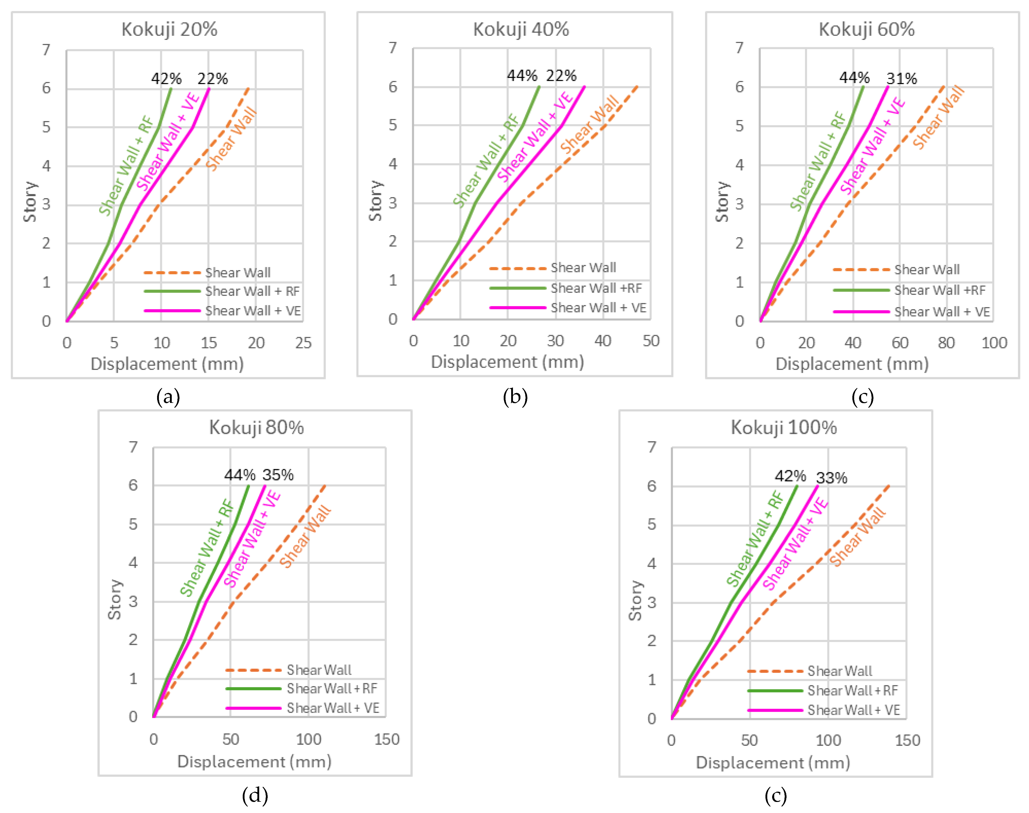
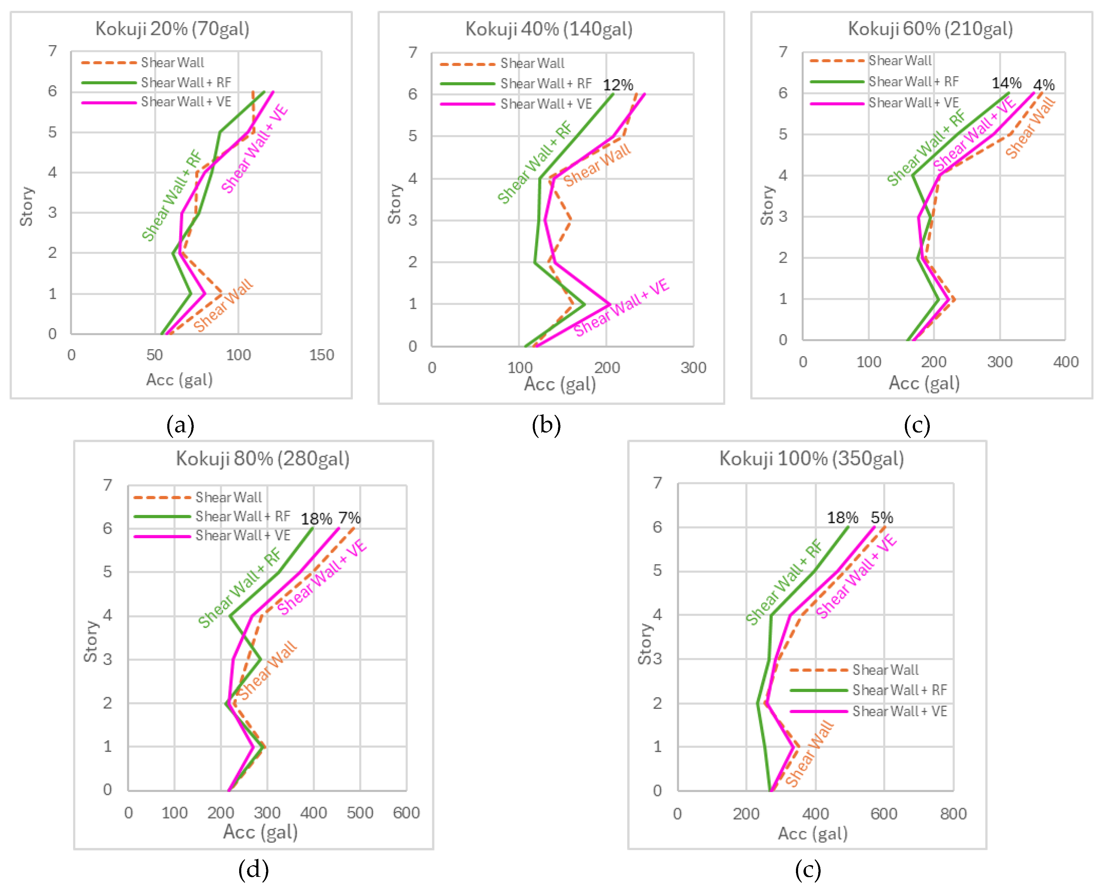
Figure 17.
The maximum displacement under Kokuji waves: (a) 20% (b) 40% (c) 60% (d) 80% (e) 100%.
Figure 18.
The maximum acceleration under Kokuji waves: (a) 20% (b) 40% (c) 60% (d) 80% (e) 100%.
4. Numerical Analysis Using STERA-3D
4.1. Introduction
In the following, numerical models of the VE damper and RF damper are constructed based on the results of the elemental test. The accuracy of the models was then verified by comparing the analytical results with shake table tests on a frame with coupled shear wall and dampers.
4.2. Numerical Model of VE Damper
Figure 19 illustrates the numerical model of the VE damper, represented by a four-element system consisting of a spring , a parallel damper , a second damper , and an additional spring [20]. The parameters and are derived from empirical formulas dependent on the shear strain γ as indicated by Equations (1), (2), and (3). These parameters exhibit power-law scaling with respect to γ, while an exponential decay term introduces a time-dependent component. The bilinear stiffness behavior of the damper is captured by the spring in Equation (4). Where, , and indicate the area, the thickness of the VE material and room temperature, respectively. Table 6 shows the parameters for adjusting the original coefficients in Ref. [20] deter-mined from the comparison of the hysteresis of the VE damper between the element test and the numerical analysis as shown in Figure 20.
4.3. Numerical Model of RF Damper
Figure 21 presents a bi-linear hysteresis depicting the moment rotation relationship of the RF damper. The graph exhibits two distinct phases: an initial elastic phase where the damper resists rotation with minimal slip, followed by a sliding phase where the moment reaches a plateau (), indicating full engagement of frictional resistance. From the schematic diagram in Figure 22, the activation moment () is calculated by Equation (5),
where represents the number of friction surfaces, is the clamping force, is the friction coefficient, and and denote the outer and inner radius of the friction interface, respectively. The parameters of the RF damper used in the shake table tests are given in Table 7, and the parameters of the hysteresis of the RF damper are given in Table 8.
4.4. Verification with Numerical Analysis (STERA-3D)
1.1.1. Numerical Model of 6 Story Coupled Wall System with Dampers
The numerical model of the 6-story coupled wall system with dampers is built using the STERA 3D, a nonlinear finite element software developed by one of the authors [21]. Figure 23 shows the interface of the STERA_3D for the test specimen. The coupling beam element is modeled as a line element with two nonlinear flexural springs for the RF dampers at both ends and one nonlinear shear spring for the VE damper at the middle as shown in Figure 24.
4.5. Results and Discussion
Figure 25 presents the maximum displacement of the structure equipped with VE dampers under five intensity levels (100%, 80%, 60%, 40%, and 20%) of Kokuji waves. From the comparison of the shear wall with VE damper (shear wall + VE) and the STERA_3D simulation (STERA 3D), the analytical and experimental results are in good agreement for all intensity levels.
Figure 26 shows the hysteresis of a VE damper under Kokuji wave excitations obtained by the STERA-3D under five intensity levels (100%, 80%, 60%, 40%, and 20%).
Figure 27 presents the maximum displacement of the structure with RF dampers under five intensity levels (100%, 80%, 60%, 40%, and 20%) of Kokuji waves. From the comparison of the shear wall with RF damper (shear wall + RF) and the STERA_3D simulation (STERA 3D), the larger the input, the closer the alignment between the analytical and test results.
Figure 28 depicts the hysteresis of a RF damper under Kokuji wave excitations obtained by the STERA-3D under five intensity levels (100%, 80%, 60%, 40%, and 20%).
5. Conclusions
The ultimate goal of this study is to develop a hybrid damper that combines VE dampers and RF dampers for use in boundary beams between coupled shear walls. As the first step, the hysteresis models for the VE damper and RF damper were constructed through element tests. Subsequently, the dampers were installed in a 6-story frame with coupled shear walls, and their effectiveness was verified through shake table tests.
The element tests successfully demonstrate the mechanical behavior and hysteretic response of both dampers. The damper characteristics obtained from these experi-mental tests provide reliable input parameters for subsequent analytical modeling.
The shake table tests were conducted using both sinusoidal and Kokuji wave ex-citations. Results demonstrated that structural walls with VE damper achieved greater story displacement reduction under sinusoidal loading, whereas RF damper exhibited superior performance under Kokuji wave excitation.
The analytical models of both dampers were constructed based on the element tests and installed to the STERA_3D software to simulate the shake table test of the 6-story specimen. The analytical results demonstrated strong agreement with tests for both VE and RF dampers, confirming the accuracy and reliability of the STERA_3D models.
Future research will focus on determining the optimal combination of damper quantities when both VE and RF dampers interact, analyzing the behavior of buildings with coupled shear walls equipped with the hybrid dampers, and developing corresponding design methods.
Author contributions
Conceptualization, T.S. and Z.N.E.M.; methodology, Z.N.E.M. and R.M; software, T.S.; writing—original draft preparation, Z.N.E.M.; writing—review and editing, T.S.; supervision, T.S. All authors have read and agreed to the published version of the manuscript.
Funding
This research received no external funding.
Institutional Review Board Statement
Not applicable.
Informed Consent Statement
Not applicable.
Data Availability Statement
The data presented in this study are available on request from the corresponding author.
Acknowledgments
The authors gratefully acknowledge the support provided by Mr. S. Sakai (Hazama Ando Corp.), Mr. Y. Yamasaki (Nishimatsu Construction Co., Ltd.), Mr. M. Uchikawa (Sato Kogyo Co., Ltd.), Mr. E. Nishimura (Toda Corp.), Mr. H. Ryujin (Maeda Co., Ltd.), Mr. R. Doi (Kumagai Gumi Co., Ltd.), and Mr. T. Kanada (Cooperative Research Facility Center, Toyohashi University of Technology). The first author appreciates MEXT scholarship for support through scholarship of doctoral degree.
Conflicts of Interest
The authors declare no conflict of interest
References
- Paulay, T.; Priestley, M.J.N. Seismic Design of Reinforced Concrete and Masonry Buildings; Wiley: New York, 1992; Vol. 768.
- Gonzalez, E. Seismic Response of Diagonally Reinforced Slender Coupling Beams (T); University of British Columbia, 2001. https://open.library.ubc.ca/collections/ubctheses/831/items/1.0063732 (accessed Oct 1, 2024).
- Aiken, I. Passive Energy Dissipation Hardware and Applications. Proc. Los Angeles County SEAOSC Symp. Passive Energy Dissip. Syst. New Exist. Build. 1996, Los Angeles.
- Soong, T.T.; Dargush, G.F. Passive Energy Dissipation and Active Control. Struct. Eng. Handb. 1999, 1–28. [Google Scholar]
- Housner, G.W.; et al. Structural Control: Past, Present, and Future. J. Eng. Mech. 1997, 123, 897–971. [Google Scholar] [CrossRef]
- Christopoulos, C.; Filiatrault, A. Principles of Supplemental Damping and Seismic Isolation; IUSS Press: Pavia, Italy, 2006.
- Montgomery, M.; Christopoulos, C. Experimental Validation of Viscoelastic Coupling Dampers for Enhanced Dynamic Performance of High-Rise Buildings. J. Struct. Eng. 2015, 141, 04014145. [Google Scholar] [CrossRef]
- Fitzgerald, T.F.; et al. Slotted Bolted Connections in Aseismic Design for Concentrically Braced Connections. Earthquake Spectra 1989, 5, 383–391. [Google Scholar] [CrossRef]
- Cavallaro, G.F.; Francavilla, A.; Latour, M.; Piluso, V.; Rizzano, G. Experimental Behaviour of Innovative Thermal Spray Coating Materials for FREEDAM Joints. Compos. Part B-Eng. 2017, 115, 289–299. [Google Scholar] [CrossRef]
- Tartaglia, R.; D’Aniello, M.; Campiche, A.; Latour, M. Symmetric Friction Dampers in Beam-to-Column Joints for Low-Damage Steel MRFs. J. Constr. Steel Res. 2021, 184. [Google Scholar] [CrossRef]
- D’Antimo, M.; Latour, M.; Demonceau, J.F. Drop-Weight Impact Tests on Free from Damage Beam to Column Connections. J. Constr. Steel Res. 2022, 192. [Google Scholar] [CrossRef]
- Colajanni, P.; La Mendola, L.; Monaco, A.; Pagnotta, S. Seismic Performance of Earthquake-Resilient RC Frames Made with HSTC Beams and Friction Damper Devices. J. Earthquake Eng. 2021, 1–27. [Google Scholar] [CrossRef]
- Steneker, P.; Wiebe, L.; Filiatrault, A. Seismic Response Comparison of Steel MRFs with Yielding and Low-Damage Connections. J. Constr. Steel Res. 2021, 179, 106502. [Google Scholar] [CrossRef]
- Loo, W.Y.; Quenneville, P.; Chouw, N. Rocking Timber Structure with Slip-Friction Connectors Conceptualized as a Plastically Deformable Hinge within a Multistory Shear Wall. J. Struct. Eng. 2016, 142. [Google Scholar] [CrossRef]
- Yousef-beik, S.M.M.; Veismoradi, S.; Zarnani, P.; Hashemi, A.; Quenneville, P. Experimental Study on Cyclic Performance of a Damage-Free Brace with Self-Centering Connection. J. Struct. Eng. 2021, 147. [Google Scholar] [CrossRef]
- Freddi, F.; Dimopoulos, C.A.; Karavasilis, T.L. Experimental Evaluation of a Rocking Damage-Free Steel Column Base with Friction Devices. J. Struct. Eng. 2020, 146. [Google Scholar] [CrossRef]
- Elettore, E.; Freddi, F.; Latour, M.; Rizzano, G. Design and Analysis of a Seismic Resilient Steel Moment Resisting Frame Equipped with Damage-Free Self-Centering Column Bases. J. Constr. Steel Res. 2021, 179. [Google Scholar] [CrossRef]
- Javidan, M.M.; Kim, J. A Rotational Friction Damper-Brace for Seismic Design of Resilient Framed Structures. J. Build. Eng. 2022, 51, 104248. [Google Scholar] [CrossRef]
- Monir, H.S.; Zeynali, K. A Modified Friction Damper for Diagonal Bracing of Structures. J. Constr. Steel Res. 2013, 87, 17–30. [Google Scholar] [CrossRef]
- Nakamura, Y.; Kaneko, M. Mechanical Modeling of Viscoelastic Damper with Amplitude- and Frequency-Dependent Properties. Proc. Second World Conf. Struct. Control 1998, 1, 181–190. [Google Scholar]
- Saito, T. Structural Earthquake Response Analysis, STERA_3D Version 11.5. http://www.rc.ace.tut.ac.jp/saito/software-e.html (accessed Oct 1, 2024).
Figure 1.
VE and RF Damper in element test: (a) front view (b) top view.
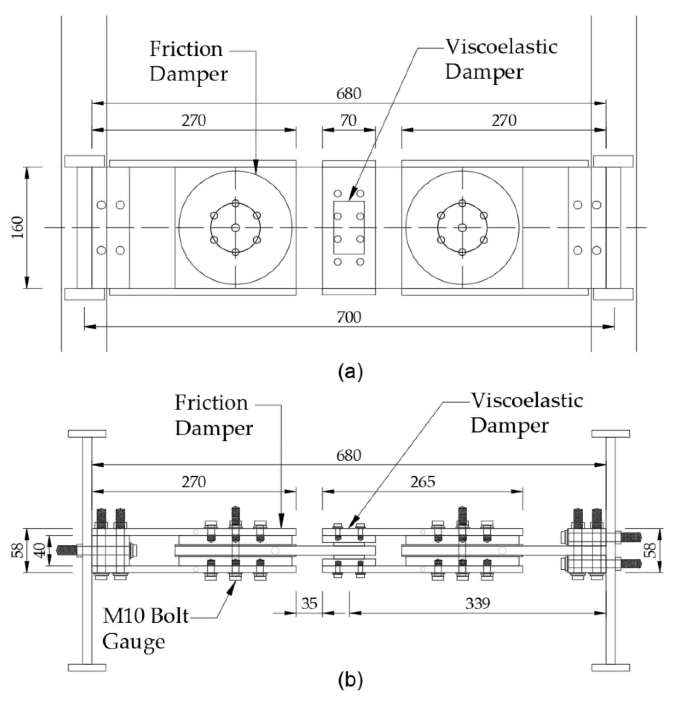
Figure 2.
Damper details: (a) front view (b) cross-section view.
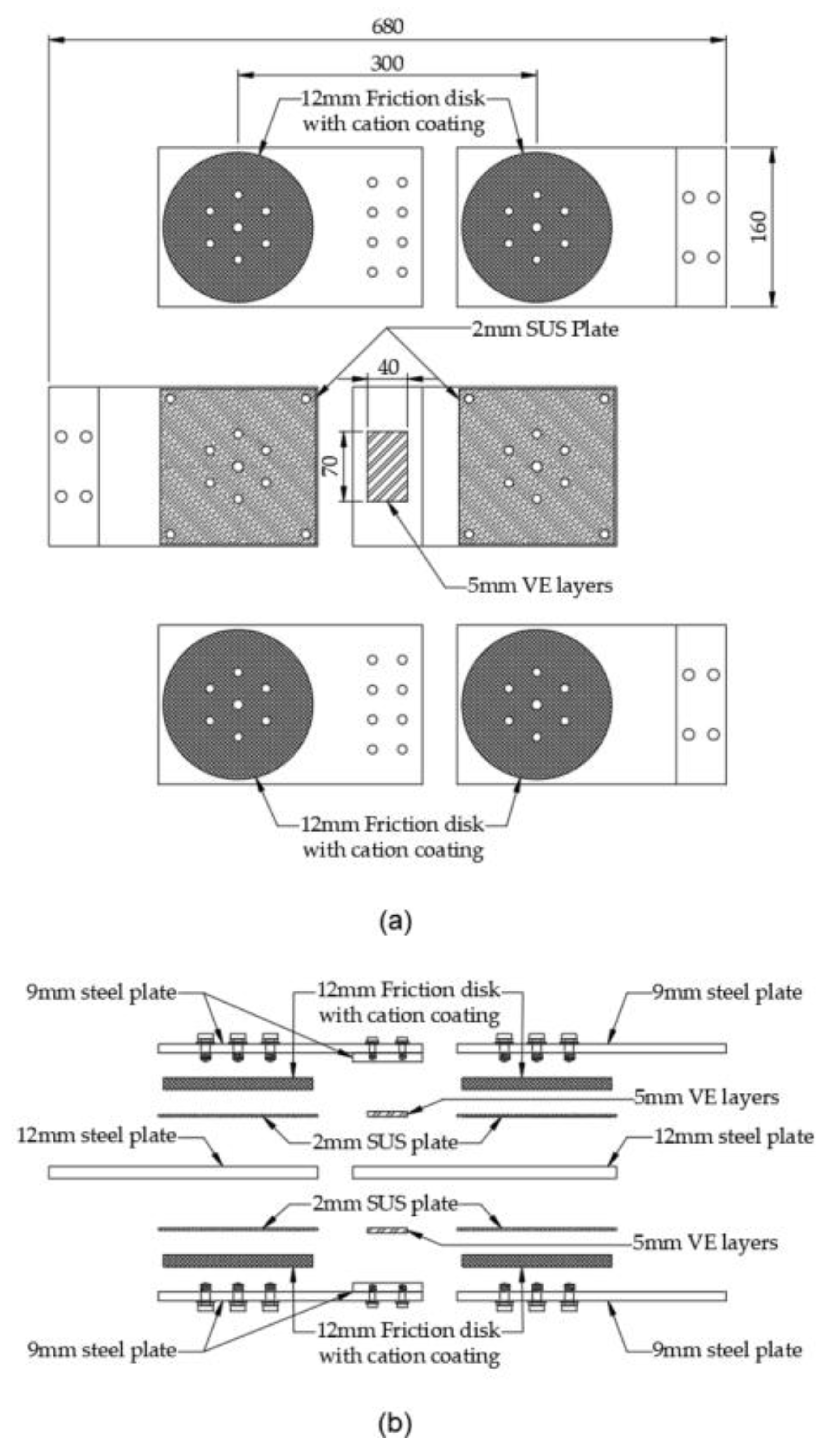
Figure 3.
Element test set up in 3D view.
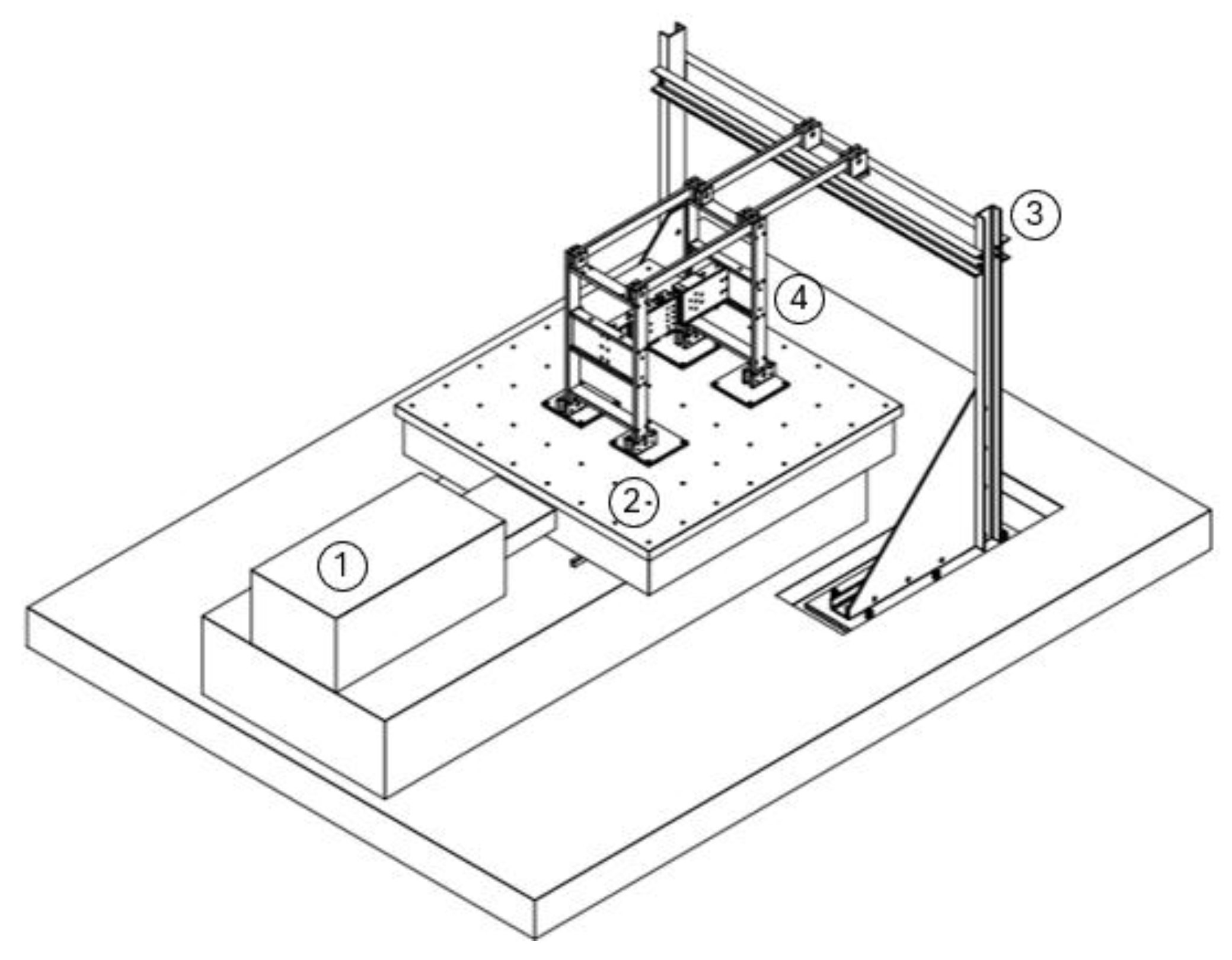
Figure 4.
Element test set up in elevation view during test.
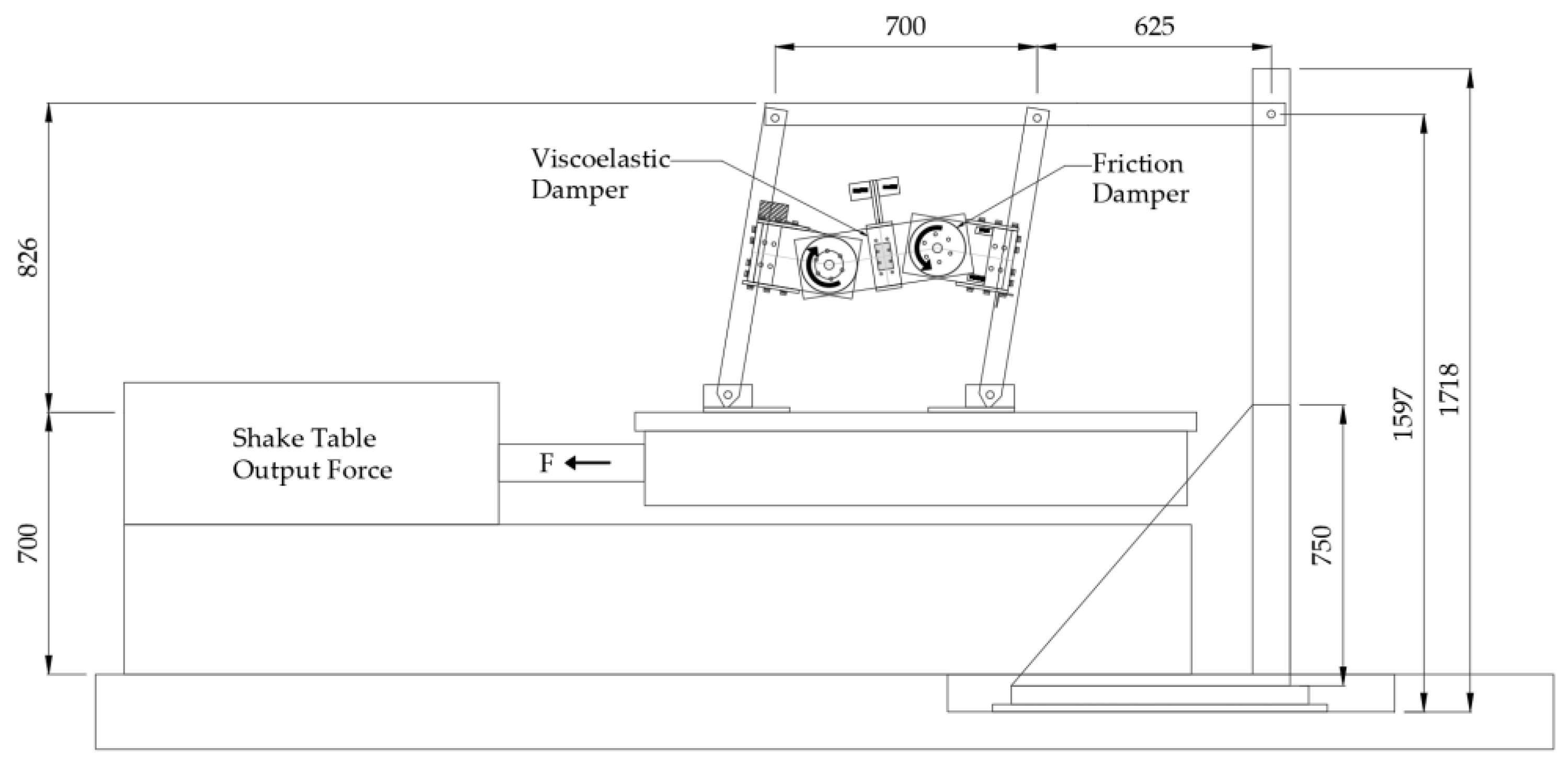
Figure 5.
Viscoelastic damper test configuration.
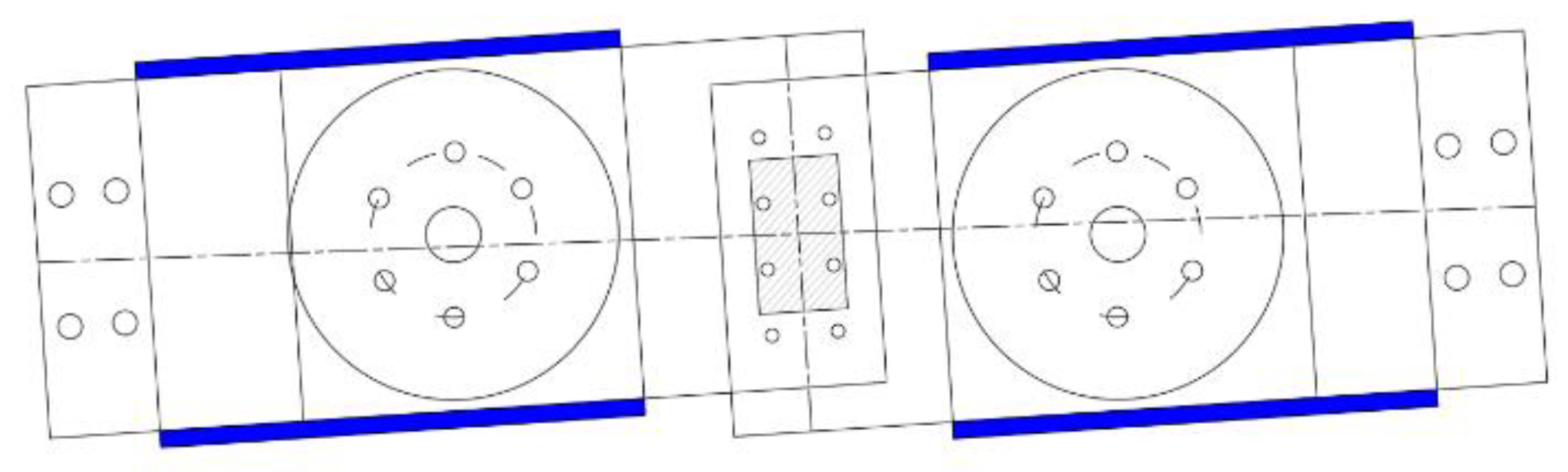
Figure 6.
Rotational friction damper test configuration.
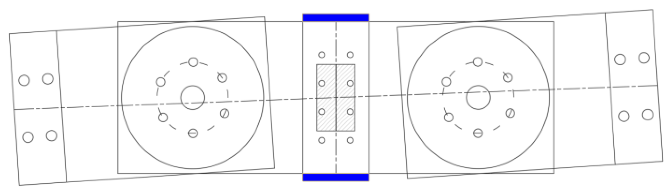
Figure 7.
Viscoelastic damper hysteresis graph.
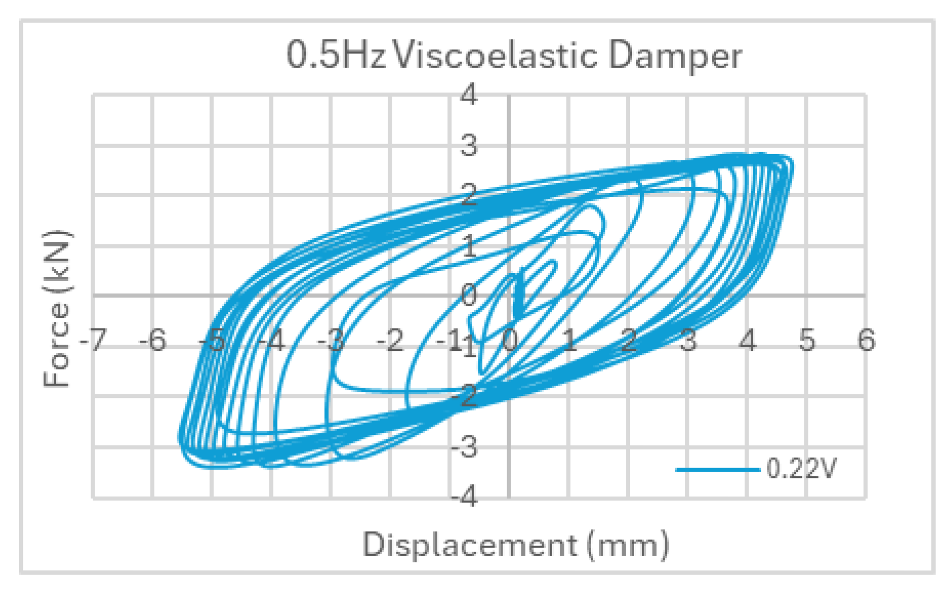
Figure 8.
Rotational friction damper hysteresis: (a) West RF, (b) East RF.
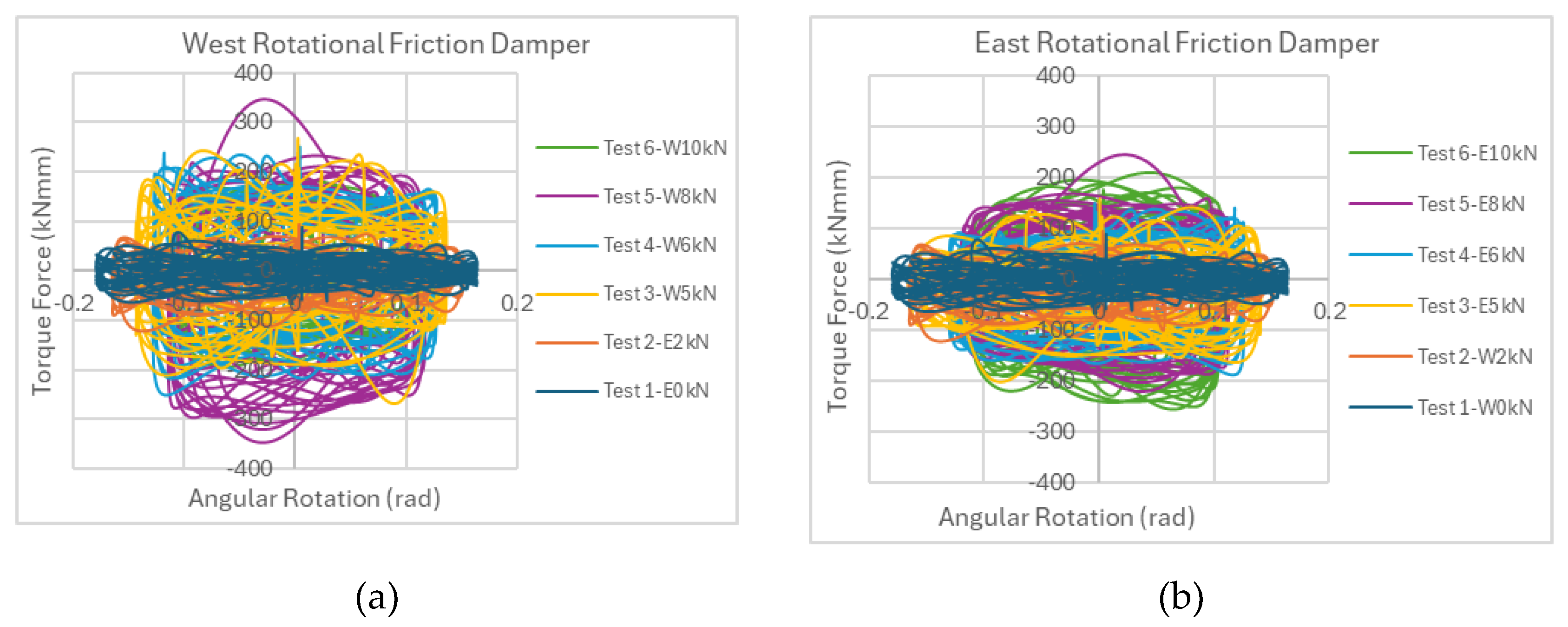
Figure 9.
Shake table experiment procedure for 6-story test specimen.
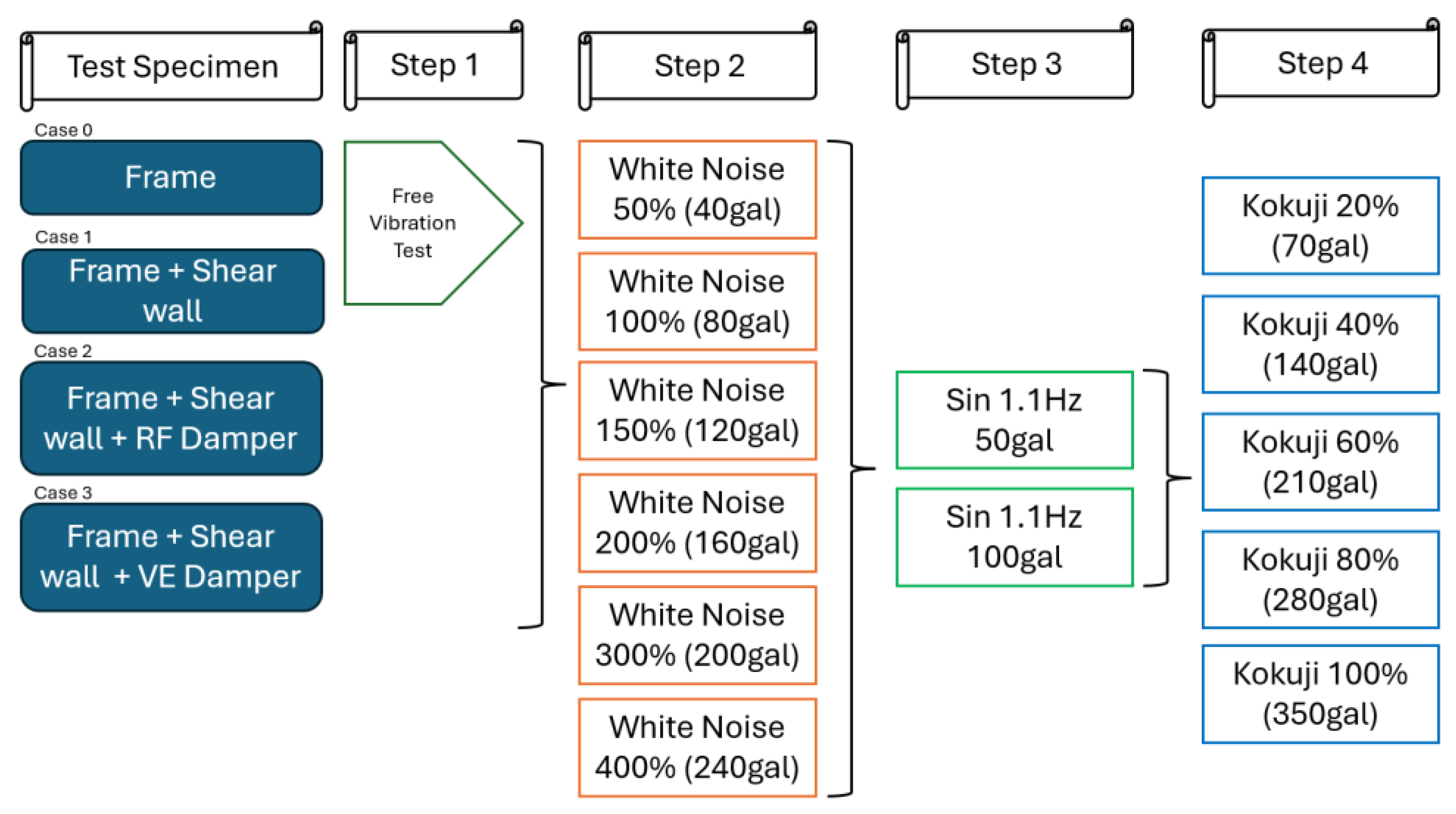
Figure 10.
Test specimen with rigid frame on shake table test.
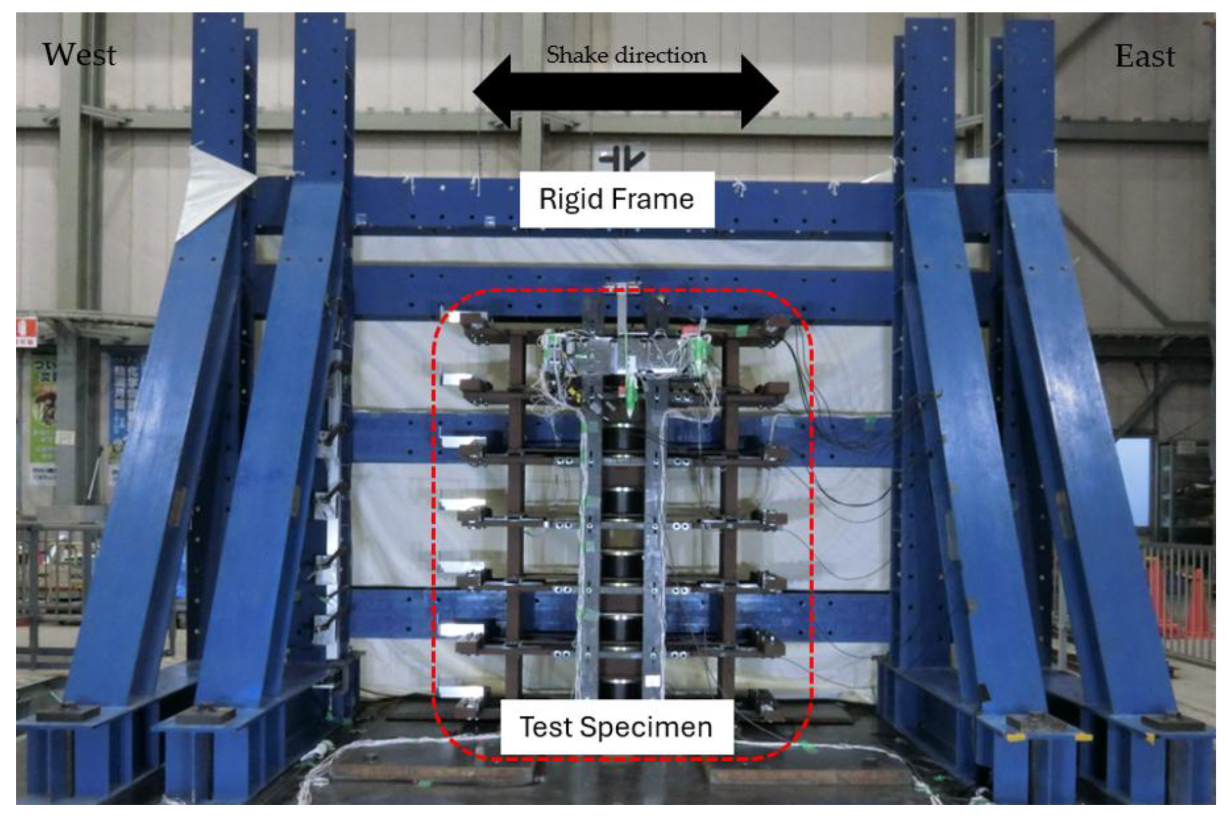
Figure 11.
Test specimen of the 6-story frame with coupled shear walls and damper.
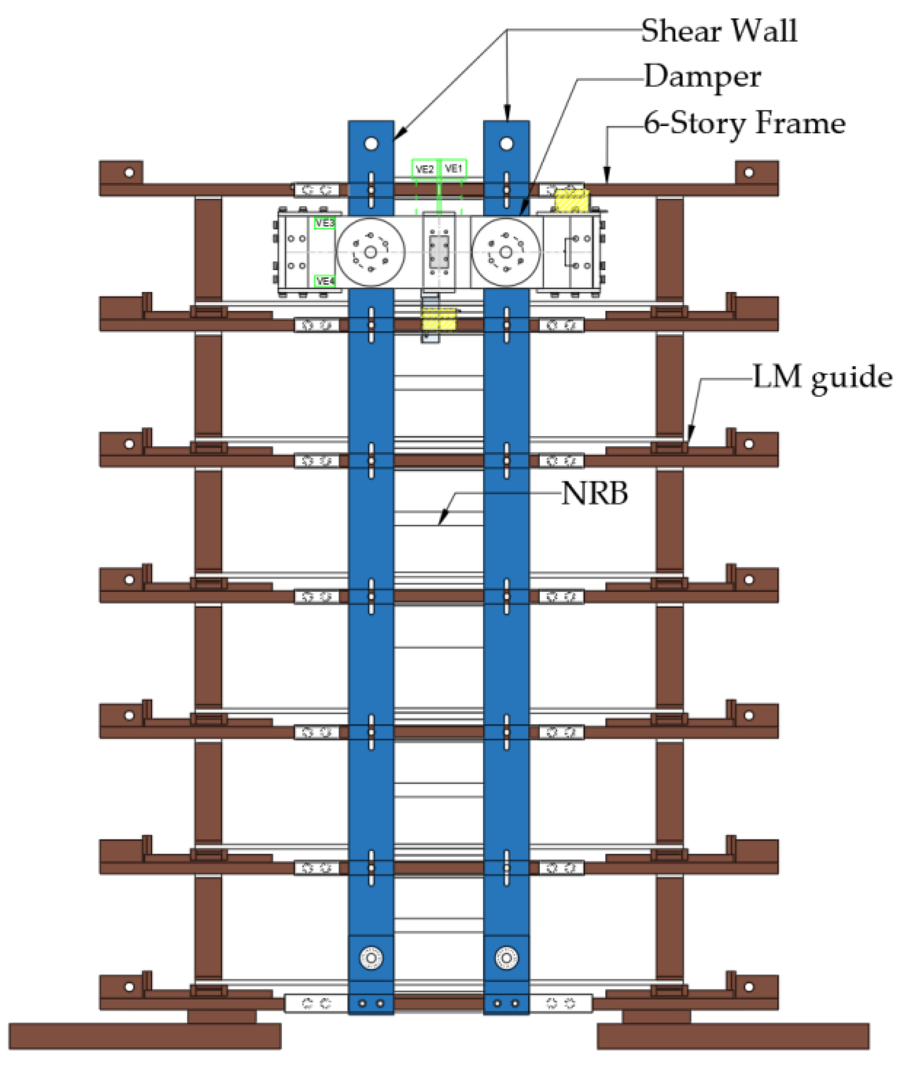
Figure 12.
Damper used for the shake table test: (a) front view (b) top view.
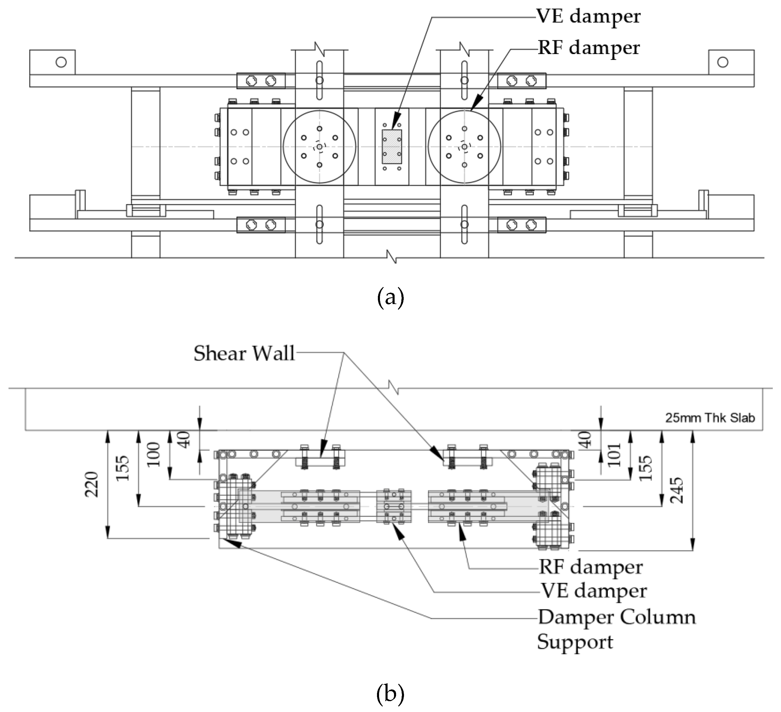
Figure 13.
Input waves for shake test: (a) white noise, (b) sinusoidal, (c) Kokuji.
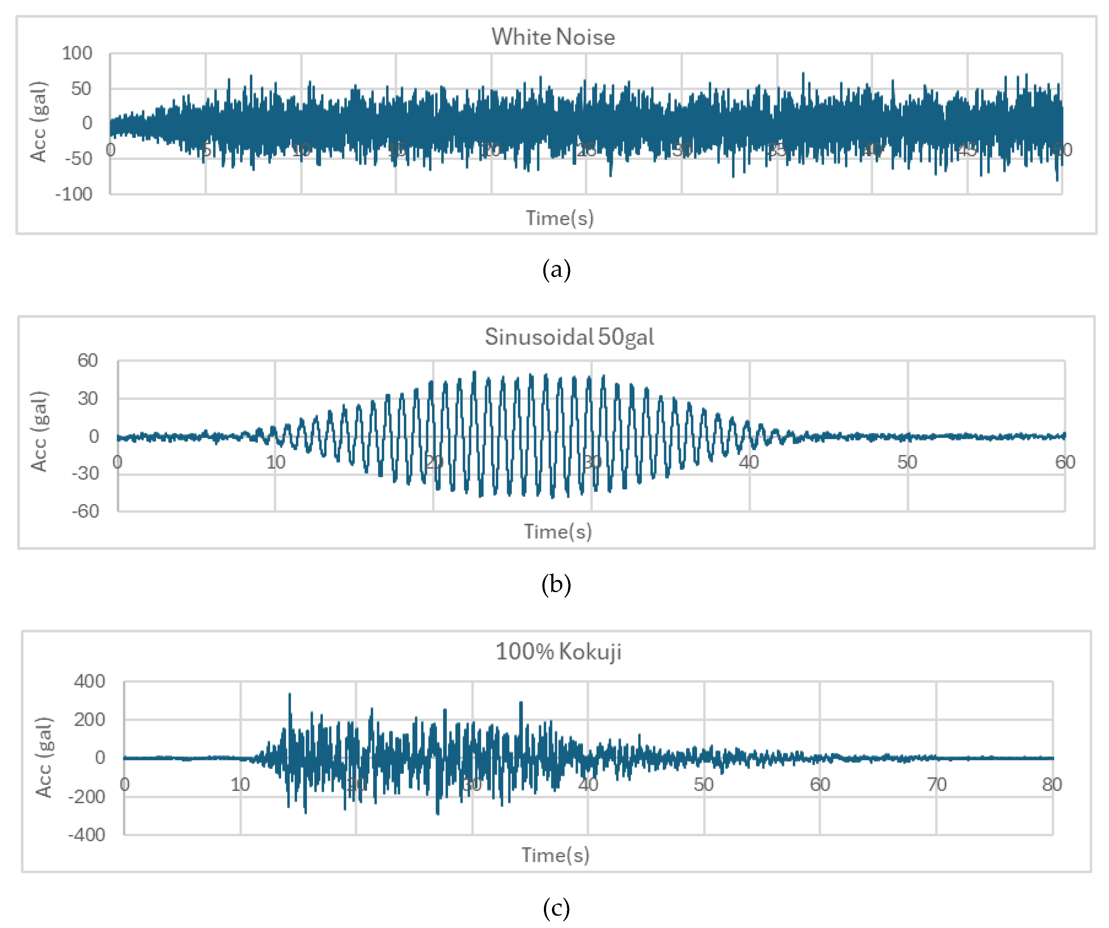
Figure 14.
Measurement device for shake table test.
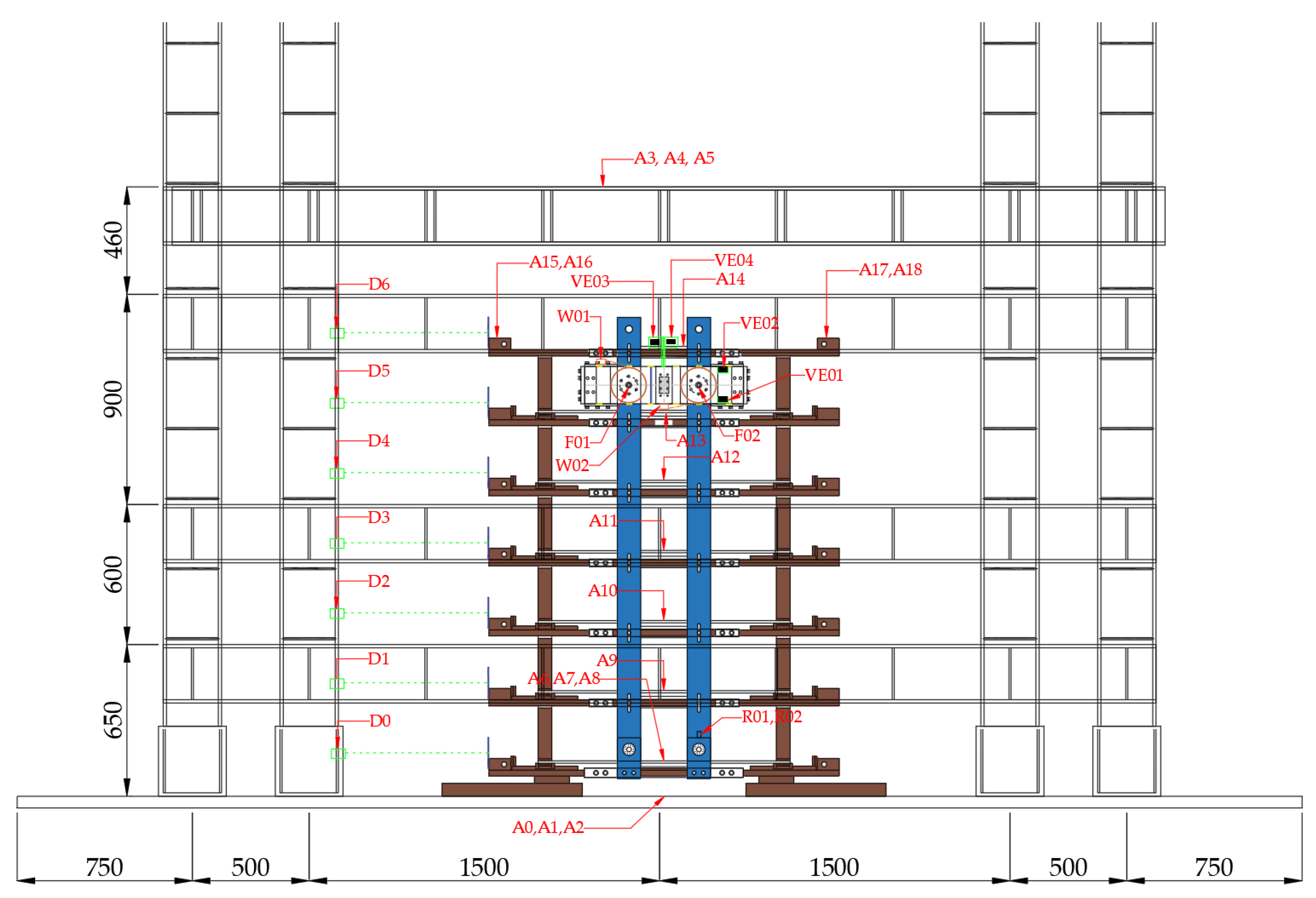
Figure 15.
The maximum displacement under sinusoidal waves: (a) 50 gal, (b) 100 gal.
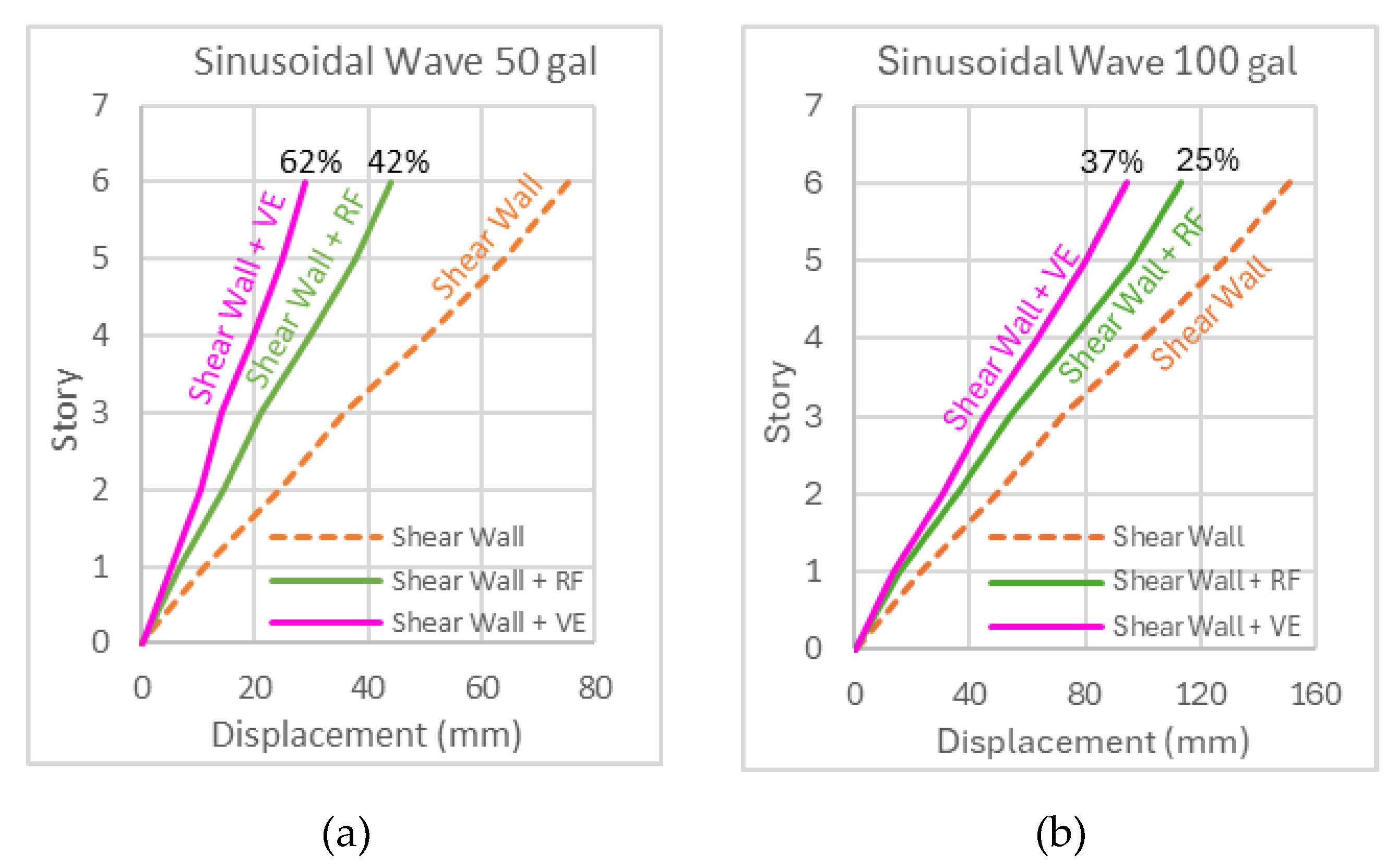
Figure 16.
The maximum acceleration under sinusoidal waves: (a) 50 gal, (b) 100 gal.
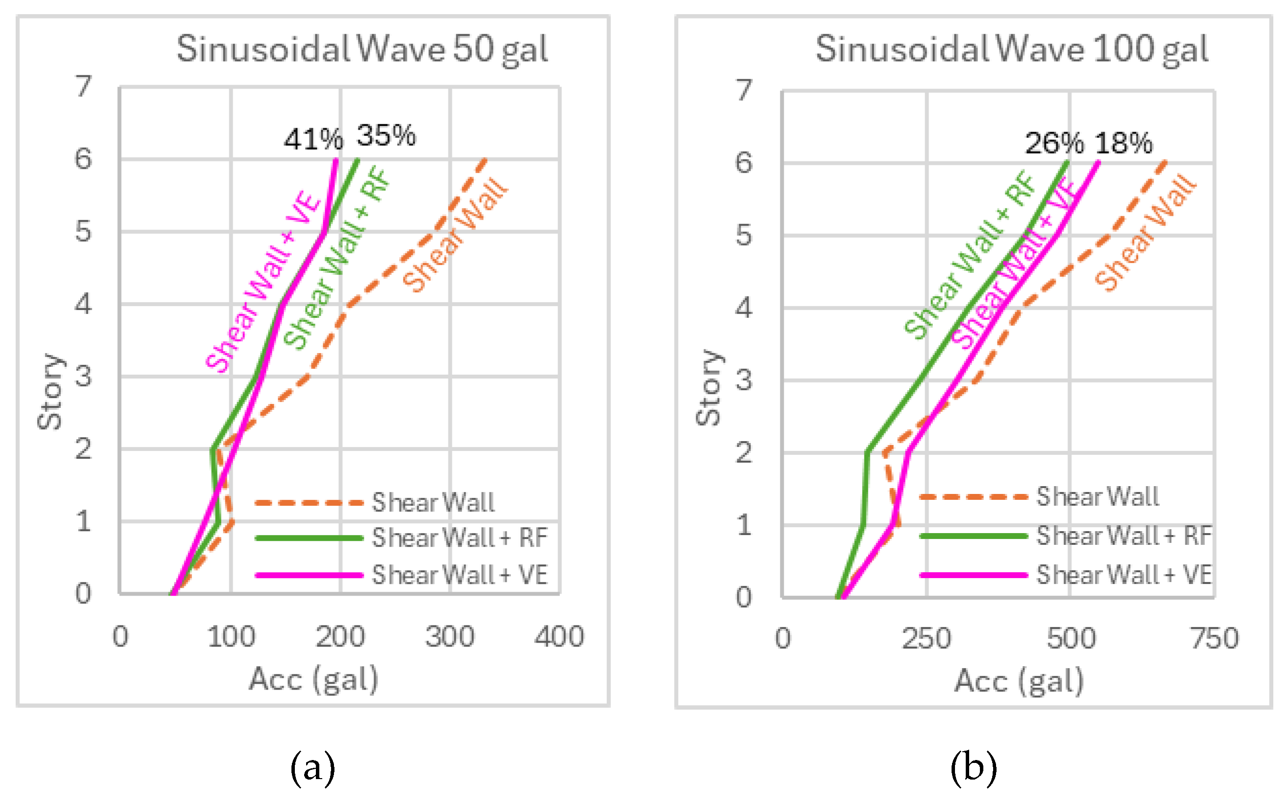
Figure 19.
Numerical model for viscoelastic damper.
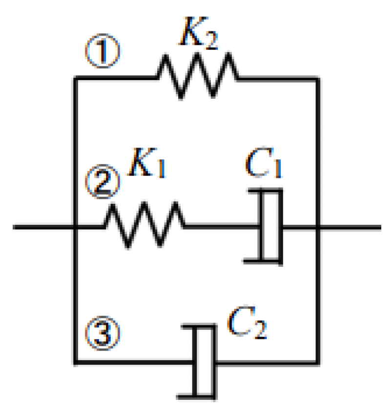
Figure 20.
Hysteresis of VE damper from element test and numerical analysis.
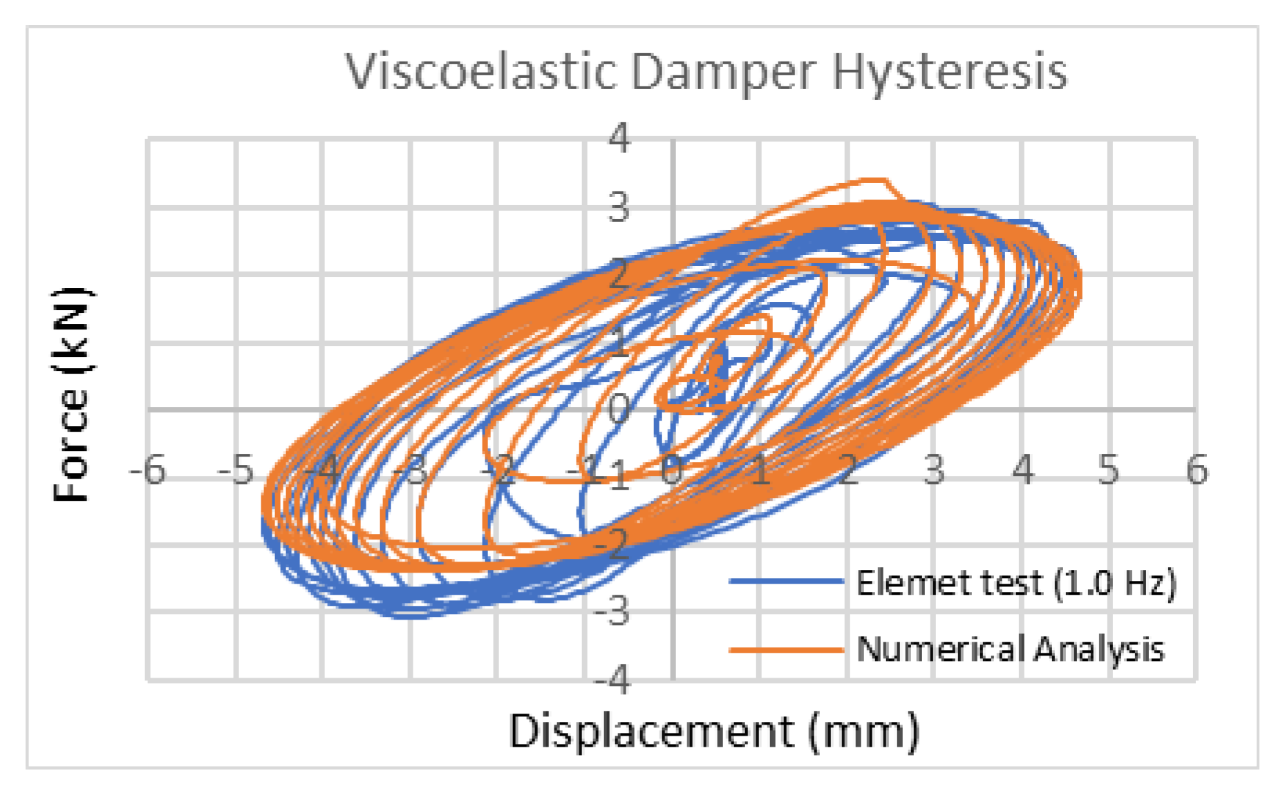
Figure 21.
Hysteresis of RF damper.
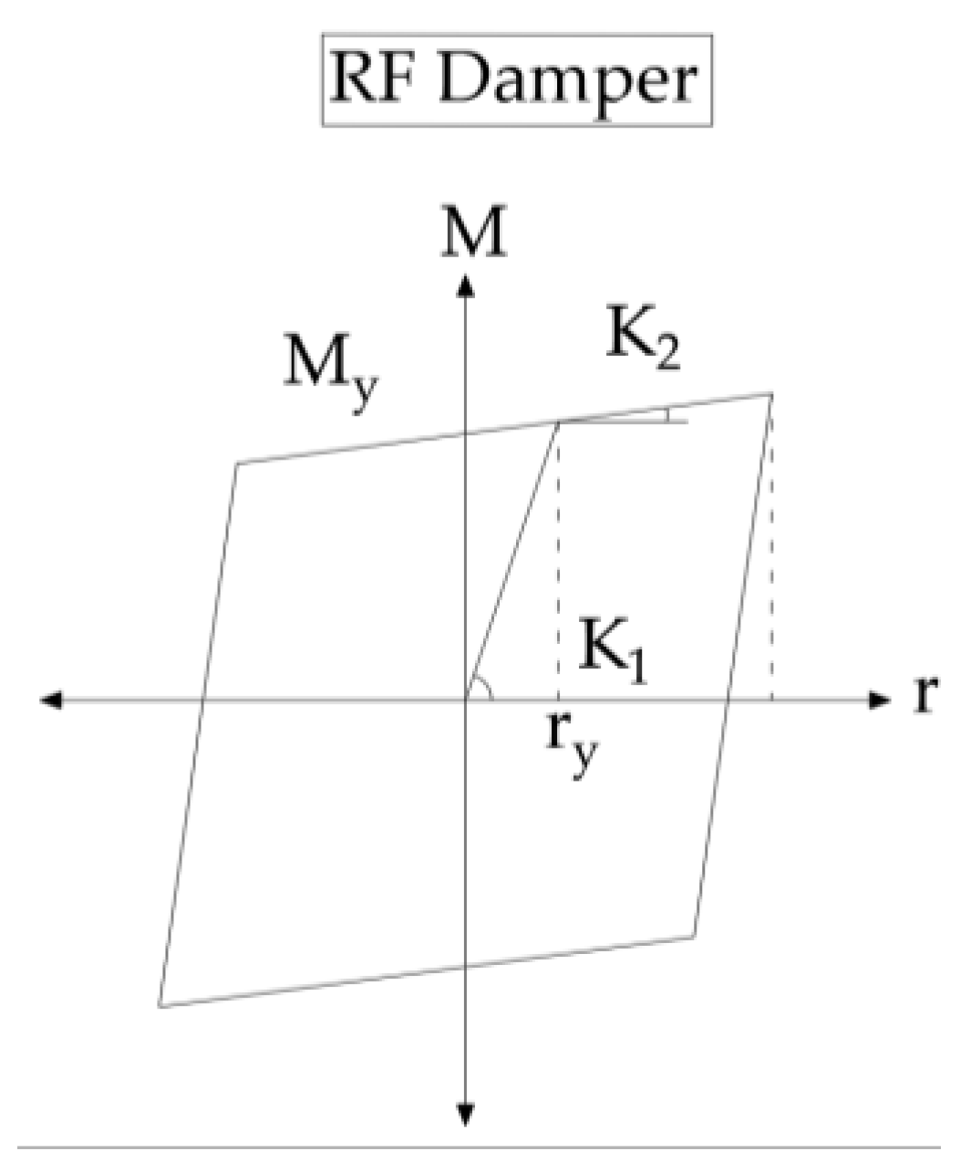
Figure 22.
Schematic diagram for calculating the activation moment of a friction disc.
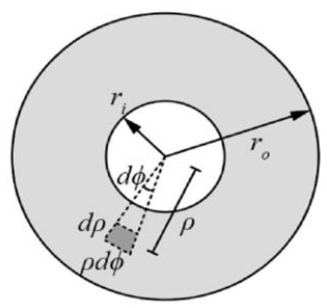
Figure 23.
Analytical model of the 6-story frame in STERA 3D.
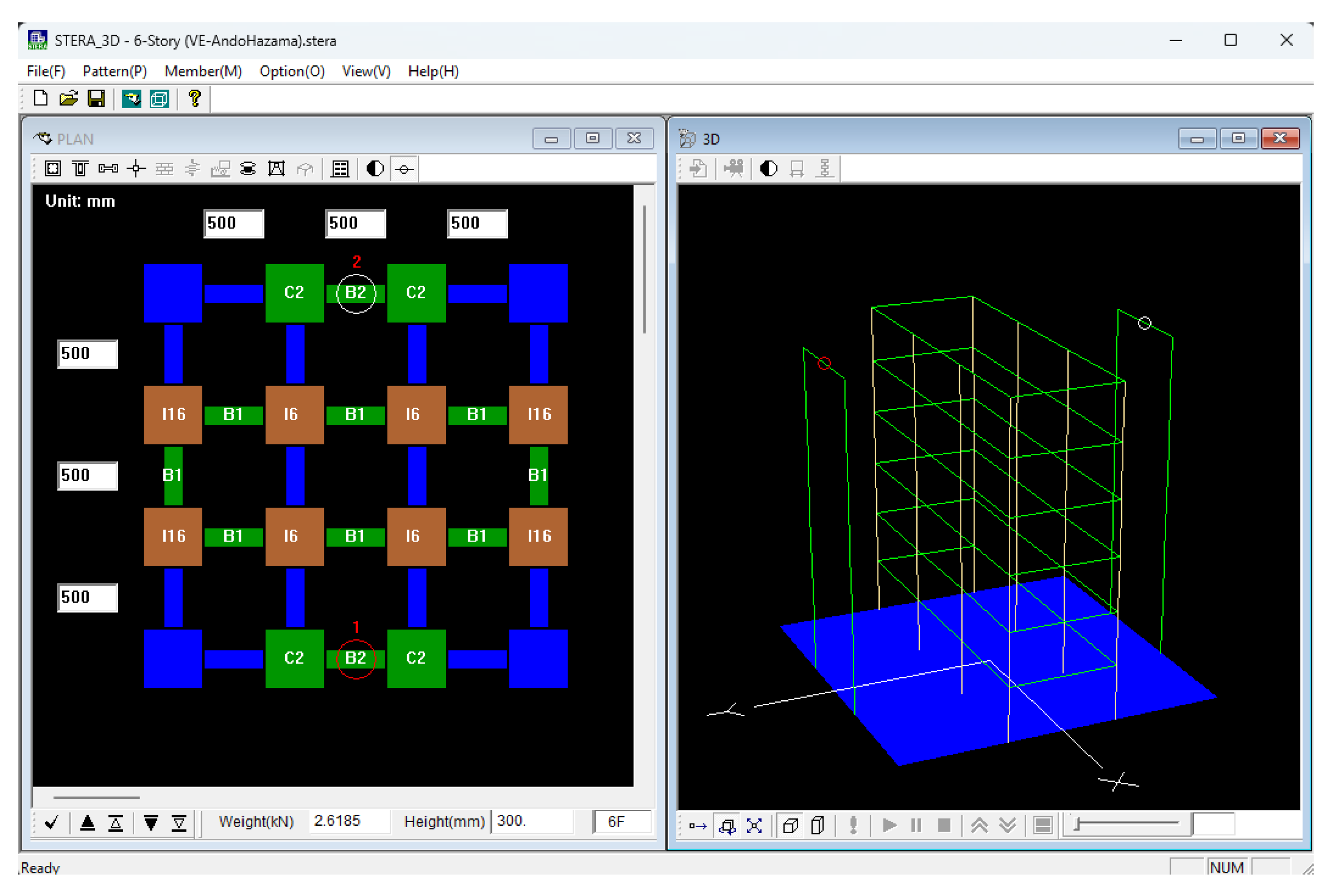
Figure 24.
Elastic, nonlinear bending (RF damper), and nonlinear shear springs (VE damper) for the coupling beam modelled by STERA_3D [21].
Figure 24.
Elastic, nonlinear bending (RF damper), and nonlinear shear springs (VE damper) for the coupling beam modelled by STERA_3D [21].
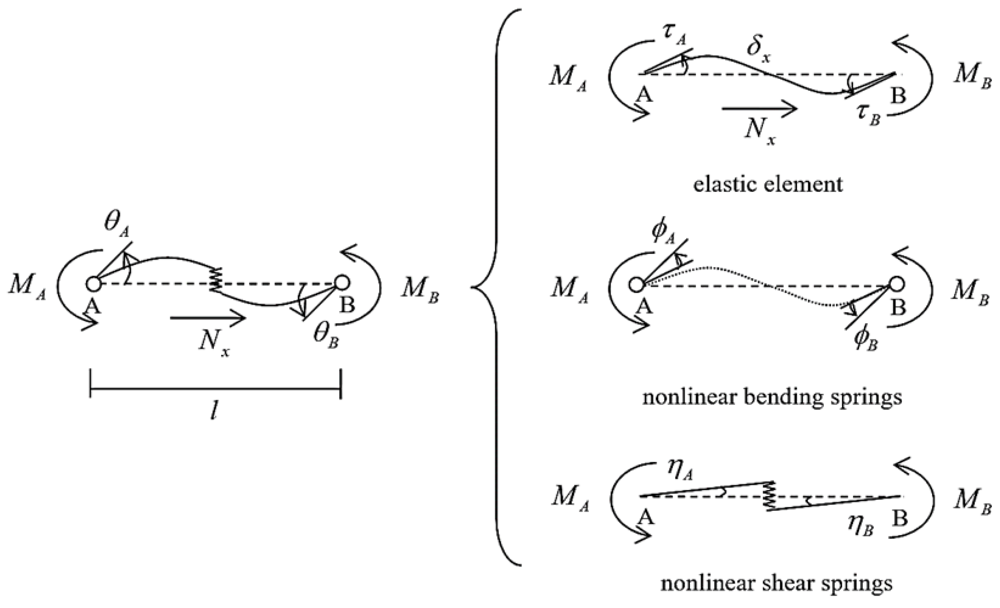
Figure 25.
Displacement of the structure with VE damper.
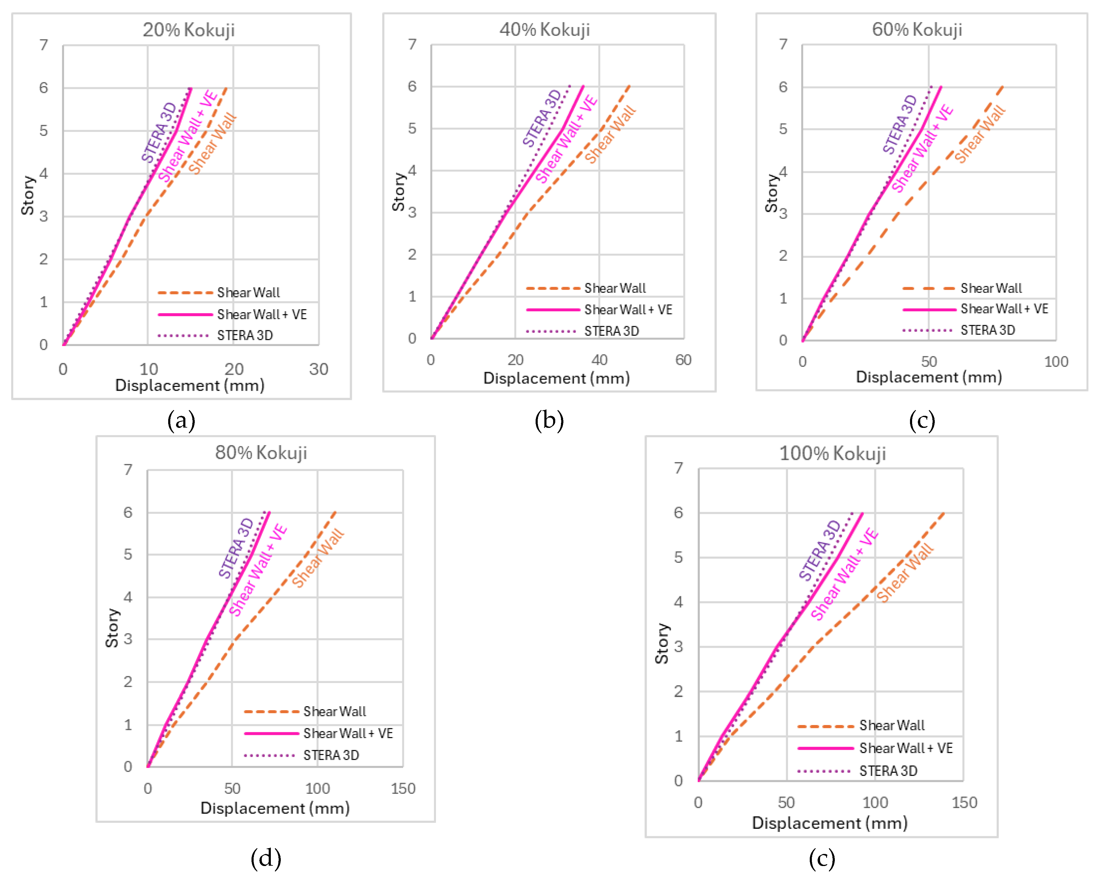
Figure 26.
Hysteresis of VE damper under Kokuji waves.
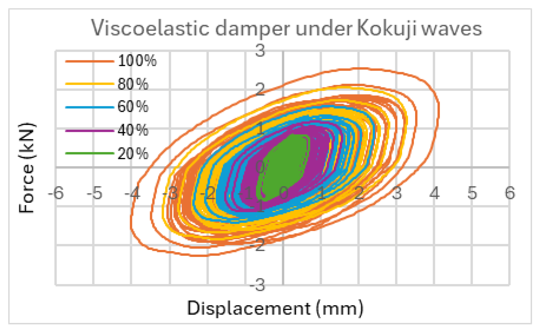
Figure 27.
Displacement of the structure with RF damper.
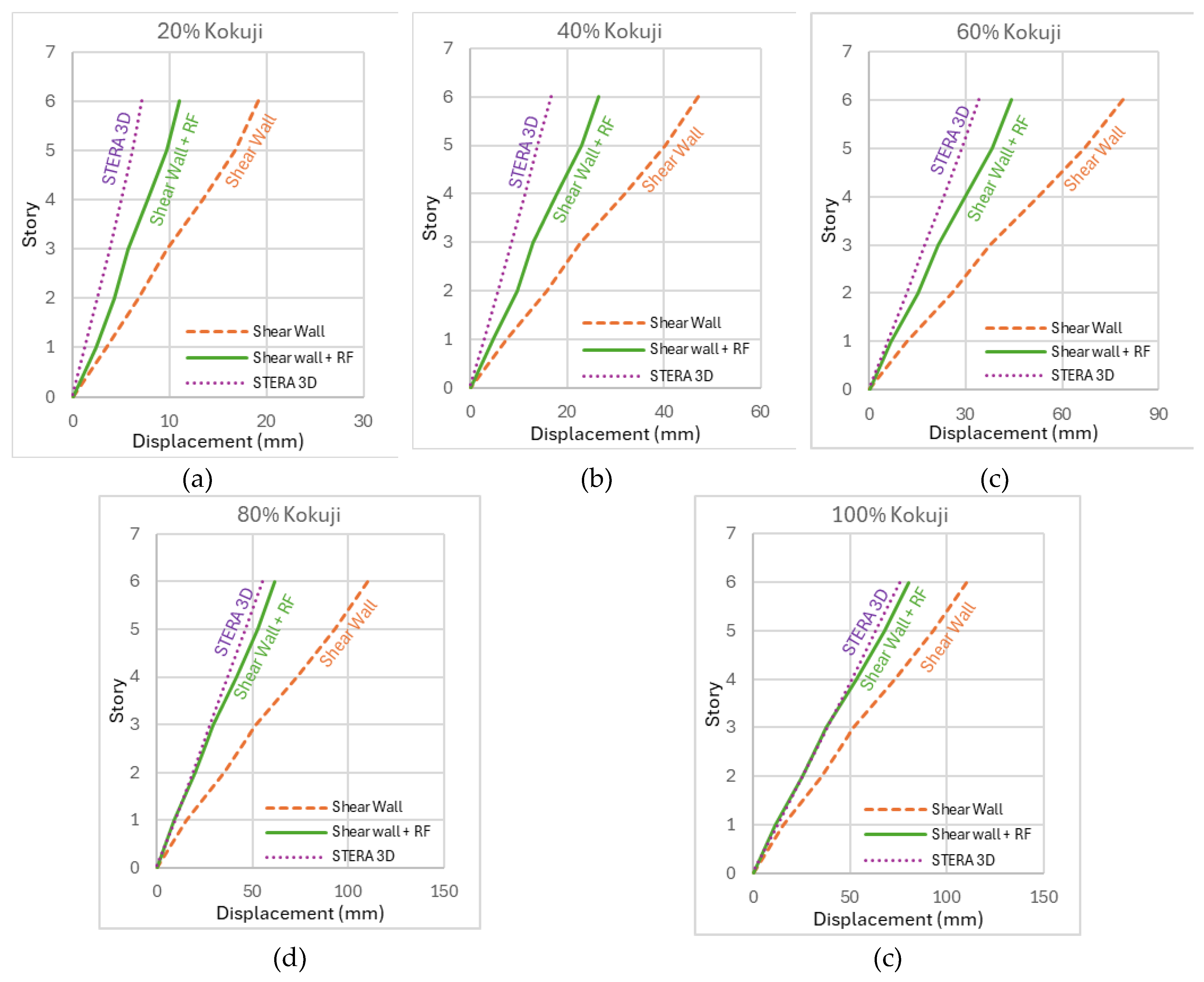
Figure 28.
Hysteresis of RF damper under Kokuji waves.
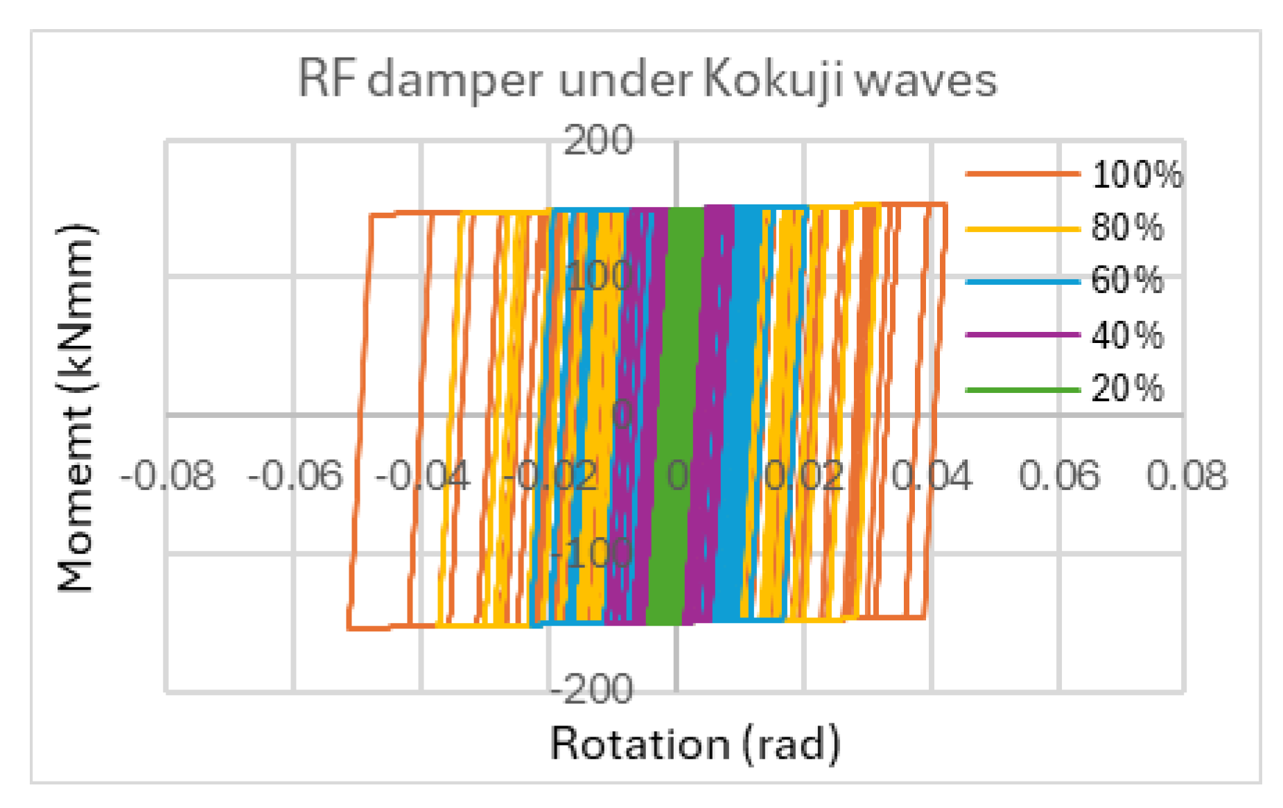

Table 1.
Damper material list.
| Type of Material | Width (mm) | Length (mm) | Radius (mm) | Thickness (mm) | No. of layer |
| VE layer | 40 | 70 | - | 5 | 2 |
| SUS plate | 156 | 156 | - | 2 | 4 |
| Friction disk | - | - | 75 | 12 | 4 |
Table 2.
Loading protocol for each damper.
| Element test | Viscoelastic Damper | Friction Damper |
| Frequency (Hz) | 0.5 | 0.5 |
| Clamping force (kN) | 0 | 5, 6, 8, 10 |
Table 3.
Rotational friction clamping force.
| Test | 1 | 2 | 3 | 4 | 5 | 6 |
| Clamping Force (kN) | 0 | 2 | 5 | 6 | 8 | 10 |
Table 4.
Properties of the 6-story frame.
| Story | Stiffness (N/mm) | Weight (N) | Height (mm) |
| 6 | 97.2 | 2,203.5 | 300 |
| 5 | 97.2 | 5,203.5 | 300 |
| 4 | 97.2 | 2,203.5 | 300 |
| 3 | 97.2 | 2,203.5 | 300 |
| 2 | 97.2 | 2,203.5 | 300 |
| 1 | 97.2 | 2,203.5 | 300 |
| 0 | - | 2,176.4 | - |
| Total | - | 15,394.4 | 1,800 |
Table 5.
Natural frequency of the 6-story frame under the white noise waves.
| White Noice intensity (gal) | Natural Frequency (Hz) |
| 40 | 2.32 |
| 80 | 1.71 |
| 120 | 1.48 |
| 160 | 1.48 |
| 200 | 1.48 |
Table 6.
Parameters for adjusting the original coefficients.
| Parameter |
|
|
|
|
|
|
|
| Value | 0.5 | 1 | 5 | 5 | 1.5 | 1 | 0.5 |
Table 7.
Parameters to calculate the activation moment of the RF damper.
| Number of friction surfaces (N) | Clamping Force (Q) | Outer Radius () | Inner Radius ( | Fric. Coefficient (μ) |
| 2 | 10 kN | 75 mm | 5 mm | 0.2 |
Table 8.
Parameter of the hysteresis of the RF damper.
| Moment () | Stiffness () | Stiffness ratio () |
| 150 kNmm | 84.23 kN/mm | 0.001 |
Disclaimer/Publisher’s Note: The statements, opinions and data contained in all publications are solely those of the individual author(s) and contributor(s) and not of MDPI and/or the editor(s). MDPI and/or the editor(s) disclaim responsibility for any injury to people or property resulting from any ideas, methods, instructions or products referred to in the content. |
© 2025 by the authors. Licensee MDPI, Basel, Switzerland. This article is an open access article distributed under the terms and conditions of the Creative Commons Attribution (CC BY) license (http://creativecommons.org/licenses/by/4.0/).
Copyright: This open access article is published under a Creative Commons CC BY 4.0 license, which permit the free download, distribution, and reuse, provided that the author and preprint are cited in any reuse.


