Submitted:
26 May 2025
Posted:
28 May 2025
You are already at the latest version
Abstract
Rapid urbanization and climate change have intensified urban flood risks, necessitat-ing resilient infrastructure to ensure water security and flood mitigation. Gravity dams are critical for regulating flood discharge, yet their seismic vulnerability poses signifi-cant challenges, particularly under compound hazards involving earthquakes and ele-vated reservoir levels. This study introduces a novel seismic analysis framework for gravity dams using the Scaled Boundary Finite Element Method (SBFEM), which effi-ciently models dam–water and dam–foundation interactions in infinite domains. A two-dimensional numerical model of a concrete gravity dam, subjected to realistic seismic loading, was developed and validated against analytical solutions and conven-tional Finite Element Method (FEM) results, achieving discrepancies as low as 0.95% for static displacements and 0.21% for natural frequencies. The SBFEM approach accu-rately captures hydrodynamic pressures and radiation damping, revealing peak pres-sures at the dam heel during resonance and demonstrating computational efficiency with significantly reduced nodal requirements compared to FEM. These findings en-hance the understanding of dam behavior under extreme loading, supporting cli-mate-adaptive design standards and integrated hydrological-structural modeling. By addressing the seismic safety of flood-control dams, this research contributes to urban flood risk mitigation and the development of resilient water management systems ca-pable of withstanding climatic and seismic extremes.
Keywords:
gravity dam
; seismic response
; urban flood mitigation
; dam–water interaction
; dam–foundation interaction
; scaled boundary finite element method (SBFEM)
; resilient infrastructure
1. Introduction
Rapid urbanization, climate change, and the increasing frequency of extreme weather events have intensified flood risks in urban areas [1,2]. As cities expand and impervious surfaces proliferate, stormwater runoff becomes more severe, and the demand for effective flood-control infrastructure continues to grow [3,4]. Among such infrastructure, gravity dams play a critical role in regulating water flow, protecting downstream urban populations, and sustaining water supply systems. However, the structural safety of these dams under seismic events remains a crucial concern, particularly in regions exposed to compound hazards involving both earthquakes and hydrological extremes [5,6].
Historically, failures or partial collapses of gravity dams during seismic events have resulted in catastrophic urban flooding and significant socio-economic damage [7,8]. For instance, the failure of small to mid-sized dams in seismically active zones has shown that inadequate consideration of seismic loading in design and evaluation can lead to uncontrolled reservoir release. These incidents underscore the importance of accurately assessing dam behavior under seismic excitation to ensure urban flood resilience [9].
Traditional numerical approaches, such as the finite element method (FEM), have been widely used to evaluate the seismic response of dam structures. However, FEM encounters limitations when modeling unbounded domains like infinite reservoirs and foundations, often requiring artificial boundary conditions that compromise accuracy or computational efficiency [10]. The Scaled Boundary Finite Element Method (SBFEM) addresses these challenges by combining the advantages of FEM and boundary element methods (BEM), enabling semi-analytical solutions for unbounded media without the need for fundamental solutions or full-domain discretization [11,12].
This study proposes an advanced seismic analysis framework for gravity dams using SBFEM, emphasizing its application in the context of urban flood risk mitigation. By independently modeling dam–water and dam–foundation interactions, the method provides a more realistic and computationally efficient representation of dynamic behavior. The ultimate aim is to contribute to the development of resilient water infrastructure capable of withstanding extreme events, thereby enhancing the reliability of urban hydrological systems and protecting densely populated areas from catastrophic flooding [13,14].
2. Methodology: Scaled Boundary Finite Element Method (SBFEM)
The seismic behavior of gravity dams arises from intricate interactions among the dam structure, the impounded water, and the underlying foundation. To model these interactions with both efficiency and precision, this study employs the Scaled Boundary Finite Element Method (SBFEM), a semi-analytical technique well-suited for analyzing infinite or semi-infinite domains. This section details the foundational principles of SBFEM, its implementation using polygonal finite elements, and its application to dam–water and dam–foundation interactions under seismic loading.
2.1. Overview of the SBFEM Framework
The SBFEM leverages the strengths of both the Finite Element Method (FEM) and the Boundary Element Method (BEM) by discretizing only the domain boundary. This approach reduces computational effort while ensuring high fidelity in modeling infinite domains, such as reservoirs and foundations. A scaling center is defined, from which the entire boundary remains visible, enabling analytical solutions along the radial direction and finite element discretization along the circumferential direction. The governing differential equation for two-dimensional static equilibrium within the SBFEM framework is introduced in Equation (1), expressing displacement and stress fields in radial and circumferential coordinates:
Where, is the radial coordinate, , and, are coefficient matrices derived from boundary discretization. The general solution of Equation (1) leads to an eigenvalue problem, as shown in Equation (2):
where is the eigenvalue, and is the corresponding eigenvector. The displacement field is subsequently expressed as a linear combination of eigenmodes along the radial direction, making this method highly effective for wave propagation and infinite domain problems due to its accuracy and computational efficiency.
2.2. Polygonal Finite Elements for Dam Body
To enhance meshing flexibility and numerical stability for complex dam geometries, polygonal finite elements are adopted to discretize the dam body. These elements provide a precise representation of boundary conditions and integrate seamlessly into the SBFEM framework. The shape functions for polygonal elements are formulated by combining radial and circumferential basis functions, as shown in Equation (3):
This construction ensures that the numerical solution accurately reflects the dam’s physical response under static and dynamic loading conditions.
2.3. Modeling of Dam–Water Interaction
The dynamic interaction between the reservoir water and the dam is modeled using a pressure-based formulation, assuming the fluid is incompressible and inviscid. The dynamic pressure field adheres to the Laplace equation, which is presented in Equation (4):
Boundary conditions—such as zero pressure at the free surface, absorbing boundaries at the far field, and continuity at the dam–water interface—are enforced by positioning scaling centers at infinity. The dynamic stiffness matrix is derived in the frequency domain using the virtual work principle and converted to the time domain via the inverse Fourier transform. This enables the computation of hydrodynamic forces on the dam surface due to seismic excitation, as expressed in Equation (5):
where is the hydrodynamic force vector, is the impulse response function (mass matrix), and is the acceleration.
2.4. Modeling of Dam–Foundation Interaction
The foundation domain is treated as an elastic half-space, and its interaction with the dam is modeled using an acceleration-based convolution integral. The dynamic stiffness of the foundation is first computed in the frequency domain and then converted to time domain using Fourier inverse transforms (Equation 6):
where represents the time-dependent stiffness function, and is the displacement at the dam–foundation interface.
This formulation allows accurate capture of radiation damping and wave reflection without requiring large mesh domains, significantly reducing computational demands.
2.5. Time-Domain Seismic Input and Solution Procedure
Seismic loading is incorporated as a time-varying acceleration at the dam base. The input motion is discretized over time steps, and Newmark-β integration is used to solve the coupled system. The total equation of motion (Equation 7) is expressed as:
where represents the earthquake-induced inertial load. Time integration proceeds iteratively for each time step, combining hydrodynamic and soil-structure interaction effects.
3. Numerical Model Setup
To validate the proposed Scaled Boundary Finite Element Method (SBFEM)-based seismic analysis framework, a two-dimensional numerical model of a concrete gravity dam is developed. This model incorporates realistic geometric features, material properties, hydrodynamic effects, and seismic loading, all simulated in the time domain.
3.1. Geometry and Material Properties of the Dam
The case study focuses on a concrete gravity dam with a height of 180 meters, a vertical upstream face, and a downstream slope of 0.75. The structure is assumed to be homogeneous and is modeled under plane strain conditions. The mechanical properties of the dam concrete are presented in Table 1, which summarizes the key parameters used in the numerical analysis.
The dam is discretized using polygonal finite elements compatible with the SBFEM formulation. The geometry and mesh configuration are illustrated in Figure 1, which is designed to ensure conformity with a reference Finite Element Method (FEM) model for comparative validation.
3.2. Reservoir and Foundation Modeling
The reservoir is modeled as a semi-infinite, incompressible, inviscid fluid with a wave propagation velocity of 1440 m/s and a density of 1000 kg/m³. Absorbing boundary conditions are applied at the far-end to simulate energy radiation, and the reservoir domain is discretized only along the dam–reservoir interface using SBFEM boundary elements.
The dam foundation is represented as an elastic half-space with the following properties: Elastic modulus: 10 GPa, Poisson’s ratio: 0.25, Density: 2000 kg/m³, Shear wave velocity: 1414 m/s.
The near-field portion of the foundation is discretized, while the infinite domain behavior is captured using a scaling center positioned beyond the foundation boundary. The nodal displacements in the X and Y directions under static conditions are shown in Figure 2. These results indicate that the displacements computed using the SBFEM-based polygonal finite element method are nearly identical to those obtained from FEM. Specifically, the maximum displacement in the X direction occurs at Node 7, with a discrepancy of 2.79% between the two methods, while the maximum displacement in the Y direction occurs at Node 10, with a discrepancy of 0.95%. This close agreement validates the accuracy of the proposed method relative to FEM.
3.3. Seismic Input and Time Discretization
The model is subjected to the ground motion recorded during the 1967 Koyna earthquake, applied in the horizontal (downstream) direction. This seismic event is widely adopted in dam safety studies as a realistic extreme loading scenario. The key parameters of the seismic input are as follows:
Total simulation time: 3.0 seconds
Time step: 0.01 seconds
Number of steps: 300
The acceleration time history of the Koyna earthquake serves as the seismic input, introduced at the dam–foundation interface as an inertial force. The time-domain solution is obtained using the Newmark-β integration method.
3.4. Mass Matrix Formulation and Natural Frequency Evaluation
To investigate the dynamic characteristics and sensitivity to mass distribution, two mass matrix formulations are evaluated for the polygonal elements: (1) the lumped mass matrix and (2) the consistent mass matrix. The first ten natural frequencies computed using these formulations are compared in Table 2, which highlights the accuracy of the proposed method against FEM results.
Displacement time histories are analyzed for the node at the dam crest and the downstream slope break point, as depicted in Figure 4. These curves, compared with FEM results, reveal that the maximum displacements in the X and Y directions at both locations occur simultaneously. The dam crest node exhibits a larger maximum displacement in the X direction, whereas the downstream slope break point shows a greater maximum displacement in the Y direction. The near-identical displacement time histories obtained from the SBFEM-based polygonal finite element method and FEM at these points confirm the reliability of the proposed approach for dynamic interaction analysis of two-dimensional gravity dams.
4. Analysis of Dam-Water Interaction
4.1. Uttarakhand Gravity Dam, Canada
To validate the dynamic water pressure model proposed in this study, the Uttarakhand Gravity Dam in Canada is analyzed, with results compared against analytical solutions. The dam stands at 84 meters in height with a water head of 70 meters, featuring a rectangular reservoir. The wave propagation velocity in water is 1440 m/s, and the water density is 1000 kg/m³. Seismic excitation is applied in the downstream direction with an acceleration of 0.3048 m/s² (equivalent to 1 ft/s²).
The dynamic water pressure distribution along the dam face, corresponding to the first natural frequency of the reservoir, is presented in Figure 5. This figure illustrates the pressure distribution for reflection of 0.25, 0.5, 0.75, and 0.925. The first natural frequency, ω1, is calculated using Equation (8):
where c is the wave propagation velocity and H is the water head height. For this dam ω1 is determined to be 32.3135 rad/s. As shown in Figure 5, the dynamic water pressure computed via the Scaled Boundary Finite Element Method (SBFEM) aligns closely with the analytical solution, with pressure increasing as the reflection coefficient rises.
Figure 6 illustrates the distribution of dynamic water pressure at different excitation frequencies with a reflection coefficient of 0.75. It can be observed that when the excitation frequency equals the natural frequency, resonance occurs, resulting in the maximum dynamic water pressure on the dam surface, with the maximum value appearing at the dam heel.
The variation of the maximum dynamic water pressure at the dam heel with excitation frequencies ranging from 0 to 20 Hz, at a reflection coefficient of 0.75, is shown in Figure 7. Two peaks are observed, corresponding to the first and second natural frequencies, with the first peak being significantly larger. Beyond the first natural frequency, the pressure decreases rapidly and stabilizes at a lower level.
4.2. Koyna Gravity Dam, India
The Koyna Gravity Dam, located near Mumbai, India, is analyzed to further validate the proposed method. Previous research by Zhao [15] utilized the modified Wilson-θ method and generalized Newmark-β methods, yielding consistent outcomes. Here, the modified Wilson-θ method serves as a reference for comparison.
The dam has a height of 103 meters, with the reservoir at full capacity. The dam material exhibits an elastic modulus of 31.5 GPa, a density of 2650 kg/m³, and a Poisson’s ratio of 0.17. The reflection coefficient at the dam base is 1.0, with water density at 1000 kg/m³ and a wave propagation velocity of 1430 m/s. A rigid foundation is assumed, and a sinusoidal acceleration excitation, is applied in the downstream direction. The analysis uses a time step of 0.01 s over 300 steps.
The displacement and acceleration time histories at the dam crest are presented in Figure 8. Results from SBFEM demonstrate high consistency with those from the modified Wilson-θ method, affirming the accuracy of the proposed approach.
5. Analysis of Dam-Foundation Interaction
5.1. Infinite Foundation Under Impulse Loading
This study examines an infinite foundation with a density of 2000 kg/m³, a Poisson’s ratio of 0.25, and an elastic modulus of 10 GPa. The foundation pit measures 139.5 m in width and 60 m in depth. An impulse load, illustrated in Figure 9, is applied at the pit’s center, with a duration of 0.2 s and a peak at 0.1 s.
In the SBFEM approach, only the interface between the near-field and far-field regions is discretized, reducing computational complexity. For validation, the Finite Element Method (FEM) is employed as a reference. In FEM, an artificial boundary is set, with the distance from the boundary to the structure satisfying Equation (9):
where is the maximum wave speed, is the shear modulus (4 GPa), is the density, and T is the load duration. The wave speed is calculated as 1414 m/s, requiring a minimum boundary distance of 141.4 m. The FEM model uses a distance of 200 m, with a mesh width of 10 m, comprising 1407 nodes and 1320 four-node elements. In contrast, the SBFEM model requires only 27 nodes and 26 elements.
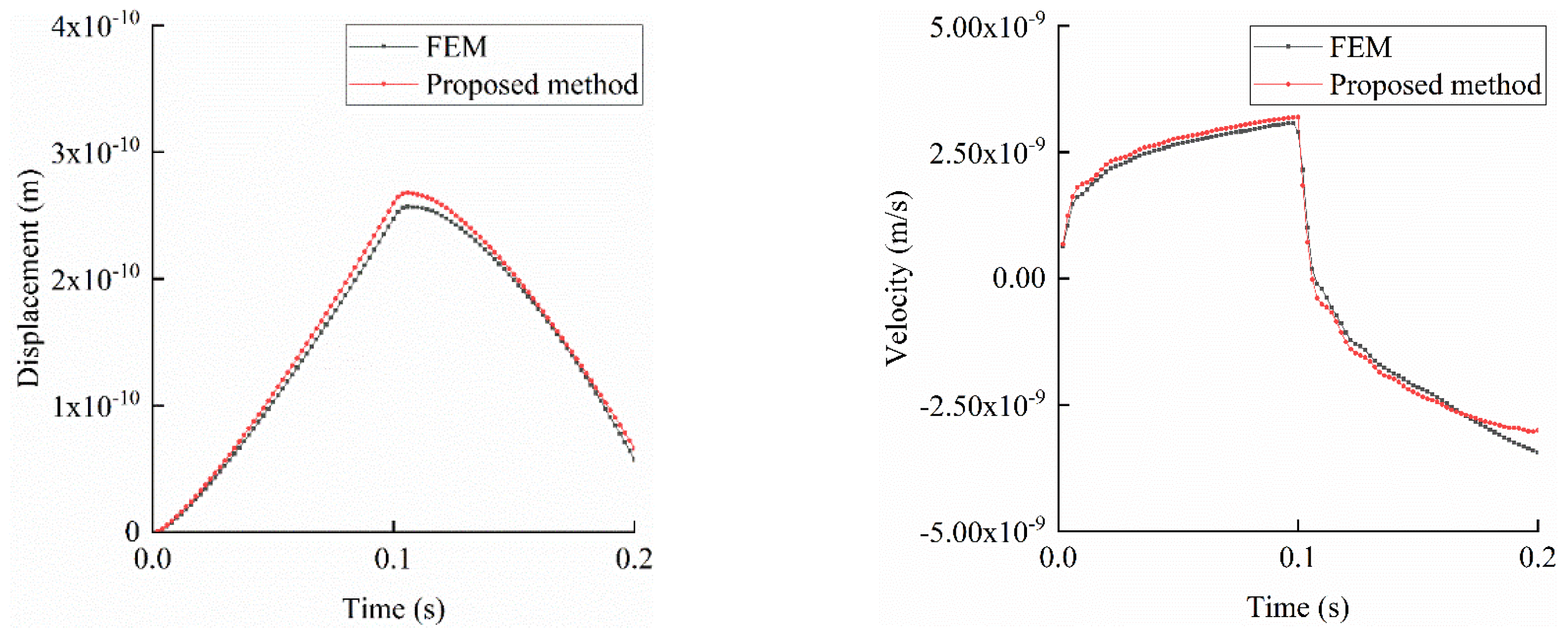
Time-domain dynamic analyses are performed over 0.2 s with a time step of 0.002 s (100 steps). The displacement and velocity time histories at the foundation’s center, shown in Figure 10, indicate that SBFEM results closely match those of FEM, confirming its efficacy for infinite foundation simulations with reduced computational effort.
Figure 10.
The history of displacement and velocity at midpoint of foundation.
5.2. Scattering Problem in a Semi-Circular Valley
This case study investigates a semi-circular valley with a radius of 55 m. The foundation has a density of 2700 kg/m³, a Poisson’s ratio of 0.333, an elastic modulus of 14.112 GPa, a shear modulus of 5.292 GPa, and a shear wave velocity of 1400 m/s. The incident wave is a unit plane harmonic Shear Vertical (SV) wave. The dimensionless frequency is defined by Equation (10):
where represents the wavelength of the harmonic wave, is the circular frequency of the harmonic wave, is the shear wave velocity, and is the radius of the semi-circular valley. Assuming η equals 0.5, we can obtain the circular frequency of the harmonic wave as 39.96 rad/s using equation (10). Therefore, the frequency of the incident wave is 6.36 Hz. Figure 11 shows the SBFE model of the semi-circular valley. The model consists of 82 nodes, with 41 nodes each for the inner and outer arcs. The inner arc represents the valley, with a radius of 55 meters, while the outer arc represents the interface between the near-field and far-field foundations, with a radius of 60 meters. The near-field foundation has a depth of 5 meters and is simulated using the finite element method with 40 elements. The far-field foundation is simulated using SBFEM, with the similar center located at the center of the ground surface.
A time-domain dynamic analysis is conducted over 3 s with a time step of 0.01 s (300 steps). The steady-state displacement amplitudes on the valley surface, compared with analytical solutions in Figure 12, show that SBFEM results closely align with analytical trends. The maximum and minimum amplitudes in the X direction are nearly identical, while Y-direction amplitudes are slightly larger, demonstrating SBFEM’s ability to simulate radiation damping effectively.
Displacement time histories at the valley center and edge, shown in Figure 13, reveal that the center stabilizes earlier than the edge due to the earlier arrival of seismic waves, with edge vibrations lagging consistently behind the center.
6. Hydrological Implications and Urban Resilience
Gravity dams function not only as structural barriers for water retention but also as critical components of integrated urban flood control systems. Their reliable performance under seismic and hydrological extremes is essential for protecting downstream urban infrastructure, population centers, and water supply networks. The findings of this study, utilizing the Scaled Boundary Finite Element Method (SBFEM), offer significant insights for hydrological engineering and urban resilience planning.
6.1. Role of Gravity Dams in Urban Flood Mitigation
In metropolitan regions, gravity dams are strategically located upstream of urban basins, serving as flood detention structures that regulate stormwater inflow and mitigate peak runoff. A failure or partial breach during seismic events, particularly under high reservoir levels, could trigger catastrophic flooding in downstream urban areas. The seismic analyses conducted in this study, as detailed in Section 4 and Section 5, incorporate realistic dam–water and dam–foundation interactions, underscoring the critical need for precise seismic performance assessments to manage urban flood risks effectively. Neglecting these interactions may lead to either an overestimation or underestimation of safety margins, resulting in either overdesigned structures or inadequate preparedness for extreme events.
6.2. Compound Hazards and Climate-Driven Extremes
Recent research highlights an increasing prevalence of compound hazards, such as simultaneous or sequential extreme events involving heavy precipitation and earthquakes. Climate change exacerbates both the frequency and intensity of extreme precipitation and elevates the likelihood of seismically critical conditions during high reservoir levels. The results presented in Section 4.1 and 4.2 demonstrate that accurate modeling of dam–water and dam–foundation interactions using SBFEM significantly moderates the seismic response and provides precise estimates of hydrodynamic forces. These findings advocate for the development of climate-adaptive design standards tailored to urban flood mitigation infrastructure capable of withstanding dual loading scenarios. The SBFEM framework, as validated in Section 3 and Section 5, facilitates the integration of structural and hydrological performance metrics, supporting comprehensive resilience-based planning.
6.3. Toward Integrated Hydrological-Structural Modeling
Historically, hydrological modeling and structural safety assessments have been conducted in isolation, limiting their ability to address the complexities of climate-resilient urban systems. The growing demand for integrated approaches necessitates coupling flow-routing models, such as the Storm Water Management Model (SWMM) or Hydrologic Engineering Center-Hydrologic Modeling System (HEC-HMS), with high-fidelity seismic-structural models. The SBFEM framework, as outlined in Section 2, offers a computationally efficient and modular approach that can be seamlessly integrated with basin-scale flood models. This enables simulation of the entire flood hazard lifecycle, from upstream inflow generation to dam response and downstream flood propagation, thereby enhancing early warning systems, emergency response strategies, and scenario-based resilience evaluations.
6.4. Implications for Policy, Design Codes, and Future Research
The outcomes of this study, building on the validations in Section 3, Section 4 and Section 5, suggest several key implications for advancing hydrological engineering practice and policy:
Mandatory Inclusion of Dynamic Interactions: Seismic safety assessments for dams upstream of urban floodplains should incorporate dynamic dam–water and dam–foundation interactions to ensure accurate risk evaluations.
Climate-Adaptive Design Guidelines: Updated standards should address compound loading scenarios driven by climate change, promoting advanced numerical methods like SBFEM for robust infrastructure design.
Scenario-Based Stress Testing: Resilience planning for critical water infrastructure should adopt stress testing under combined flood–earthquake scenarios to enhance preparedness.
Interdisciplinary Collaboration: Effective risk-informed frameworks require collaboration among hydrologists, geotechnical engineers, and urban planners to integrate structural and hydrological perspectives.
These recommendations align with the need for resilient urban water management systems capable of addressing the challenges posed by climate change and urbanization.
7. Conclusions
This study presents a comprehensive framework for evaluating the seismic performance of gravity dams using the Scaled Boundary Finite Element Method (SBFEM), with a focus on its implications for urban flood risk mitigation. By integrating realistic dam–water and dam–foundation interactions, as detailed in Section 4 and Section 5, the proposed methodology offers a robust and computationally efficient approach to modeling complex dynamic responses in dam–reservoir–foundation systems.
The numerical model developed in Section 3, incorporating a two-dimensional concrete gravity dam subjected to the 1967 Koyna earthquake, demonstrates the SBFEM’s ability to capture critical structural and hydrodynamic behaviors with high accuracy. Validation against analytical solutions and established methods, such as the modified Wilson-θ method for the Koyna Gravity Dam (Section 4.2) and FEM for infinite foundation analysis (Section 5.1), confirms that SBFEM results align closely with reference solutions, achieving discrepancies as low as 0.95% for static displacements and 0.21% for natural frequencies. These findings underscore the method’s precision in simulating wave propagation, radiation damping, and infinite domain effects, surpassing the limitations of conventional FEM, which often requires artificial boundary conditions.
The analyses of dam–water interactions (Section 4) reveal that hydrodynamic pressures peak at the dam heel during resonance, with accurate modeling of reflection coefficients and excitation frequencies being critical for reliable predictions. Similarly, dam–foundation interaction studies (Section 5) highlight SBFEM’s efficiency, reducing the computational burden by discretizing only the near-field interface, as evidenced by the use of just 27 nodes compared to FEM’s 1407 nodes in the infinite foundation case. These technical advancements enhance the understanding of seismic responses under extreme loading conditions.
From a hydrological perspective, as discussed in Section 6, the study emphasizes the pivotal role of gravity dams in urban flood mitigation. The accurate assessment of seismic performance, enabled by SBFEM, is vital for preventing catastrophic downstream flooding, particularly under compound hazards exacerbated by climate change. The proposed framework’s modular nature supports its potential integration with basin-scale hydrological models, such as SWMM or HEC-HMS, facilitating holistic simulations of flood hazard lifecycles. This interdisciplinary approach aligns with the growing need for climate-resilient urban water management systems.
The findings advocate for several practical and policy-oriented implications. Seismic safety assessments should mandate the inclusion of dynamic interaction effects, and design standards must evolve to address climate-driven compound loading scenarios. Furthermore, scenario-based stress testing and interdisciplinary collaboration among hydrologists, geotechnical engineers, and urban planners are essential for developing risk-informed resilience frameworks.
Future research directions include extending the SBFEM framework to three-dimensional dam models to account for complex geometries, coupling it with advanced hydrological models for full-scenario flood simulations, and exploring multi-hazard scenarios to enhance climate resilience. These advancements will contribute to refining dam safety codes and ensuring the robustness of critical water infrastructure in urban settings.
In summary, this study advances the seismic analysis of gravity dams through the application of SBFEM, offering both technical precision and practical relevance for urban flood risk management. By bridging structural and hydrological perspectives, it provides a foundation for designing resilient infrastructure capable of withstanding the challenges posed by seismic and climatic extremes.
References
- Kundzewicz, Z.W.; Kanae, S.; Seneviratne, S.I.; Handmer, J.; Nicholls, N.; Peduzzi, P.; Mechler, R.; Bouwer, L.M.; Arnell, N.; Mach, K. Flood risk and climate change: global and regional perspectives. Hydrol. Sci. J. 2014, 59, 1–28. [Google Scholar] [CrossRef]
- Zhou, Q.; Mikkelsen, P.S.; Halsnæs, K. Framework for economic pluvial flood risk assessment considering climate change effects and adaptation benefits. J. Hydrol. 2012, 414–415, 539–549. [CrossRef]
- Wang, Y.; He, B.; Takara, K.; Kim, S.; Kalra, A.; Ahmadalipour, A. Urbanization Effects on Runoff and Flooding: A Review of Modeling Tools. Water 2018, 10, 714. [Google Scholar] [CrossRef]
- Salvadore, E.; Bronders, J.; Batelaan, O. Hydrological modelling of urbanized catchments: A review and future directions. J. Hydrol. 2015, 529, 62–81. [Google Scholar] [CrossRef]
- Bhattacharjee, S.; Chatterjee, C. Review on the impact of climate change and natural hazards on dams and reservoirs. Nat. Hazards 2022, 110, 1567–1589. [Google Scholar] [CrossRef]
- Xu, G.; Zhang, J.; Wang, D.; Song, C. Scaled boundary finite element method for seismic safety assessment of concrete gravity dams. Appl. Math. Model. 2023, 120, 747–763. [Google Scholar] [CrossRef]
- Chopra, A.K.; Chakrabarti, P. The Koyna Earthquake and the Damage to Koyna Dam. Bull. Seismol. Soc. Am. 1973, 63, 381–397. [Google Scholar] [CrossRef]
- Jansen, R. Dams and Public Safety; U.S. Department of the Interior, Bureau of Reclamation: Denver, CO, USA, 1980. [Google Scholar]
- Xu, H.; Xu, Y.; Dai, H.; Li, D. Seismic performance of concrete gravity dams under combined reservoir water levels and ground motions. Soil Dyn. Earthq. Eng. 2019, 116, 538–552. [Google Scholar] [CrossRef]
- Bathe, K.J. Finite Element Procedures; Prentice Hall: Upper Saddle River, NJ, USA, 2006. [Google Scholar]
- Song, C.; Wolf, J.P. The Scaled Boundary Finite-Element Method—Alias Consistent Infinitesimal Finite-Element Cell Method—For Elastodynamics. Comput. Methods Appl. Mech. Eng. 1997, 147, 329–355. [Google Scholar] [CrossRef]
- Ooi, E.T.; Song, C.; Tin-Loi, F.; Yang, Z.J. Automatic Modelling of Cohesive Crack Propagation in Concrete Using Polygon Scaled Boundary Finite Elements. Eng. Fract. Mech. 2012, 93, 13–33. [Google Scholar] [CrossRef]
- UNDRR. Global Assessment Report on Disaster Risk Reduction 2019; United Nations Office for Disaster Risk Reduction: Geneva, Switzerland; Available online: https://gar.undrr.org/2019.
- IPCC. Climate Change 2021: Impacts, Adaptation and Vulnerability; Intergovernmental Panel on Climate Change: Geneva, Switzerland, 2021. Available online: https://www.ipcc.ch/report/ar6/wg2/.
- Zhao L (2006) Seismic analysis of arch dams with contraction joints and dam-water-foundation interaction. Hohai University.
Figure 1.
Geometry and polygonal mesh configuration of the gravity dam used in the SBFEM simulation.
Figure 1.
Geometry and polygonal mesh configuration of the gravity dam used in the SBFEM simulation.
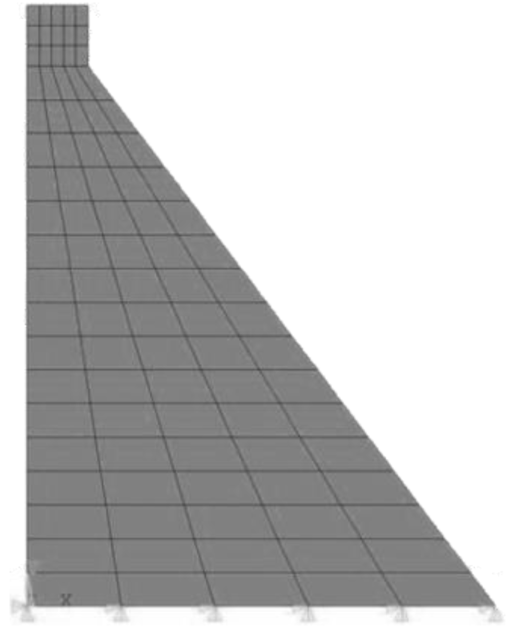
Figure 2.
Nodes displacement in X and Y directions.
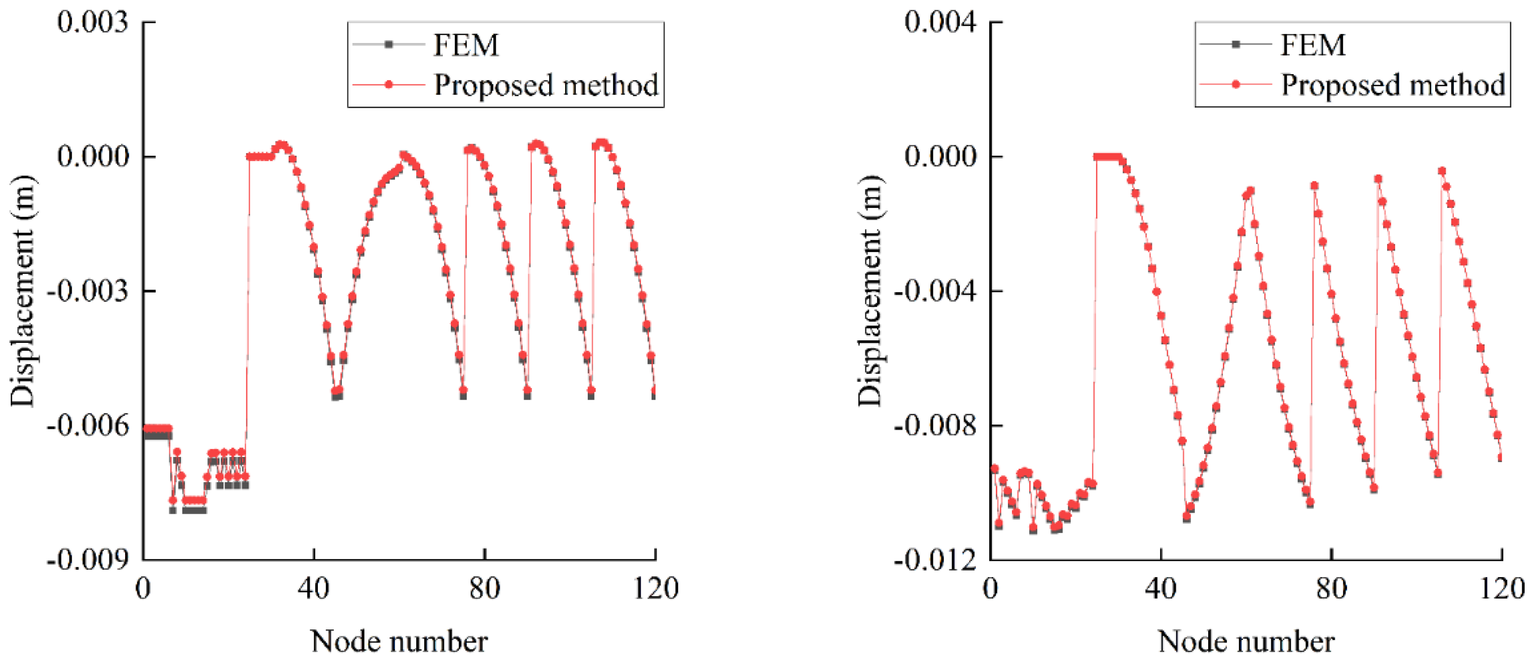
Figure 4.
The history of displacement at the dam crest and downstream slope.
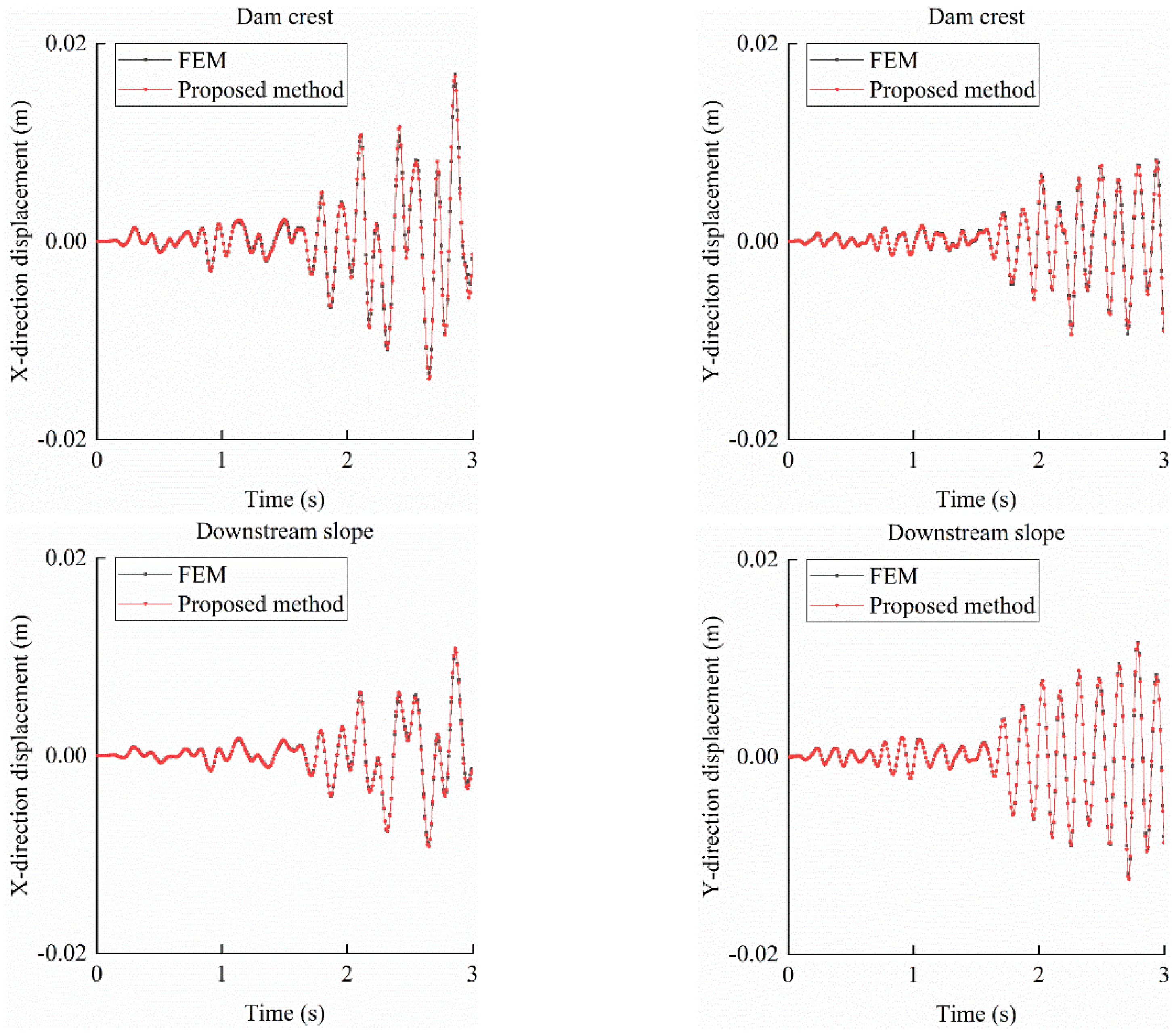
Figure 5.
Dynamic water pressure on dam surface under different reflection coefficients.
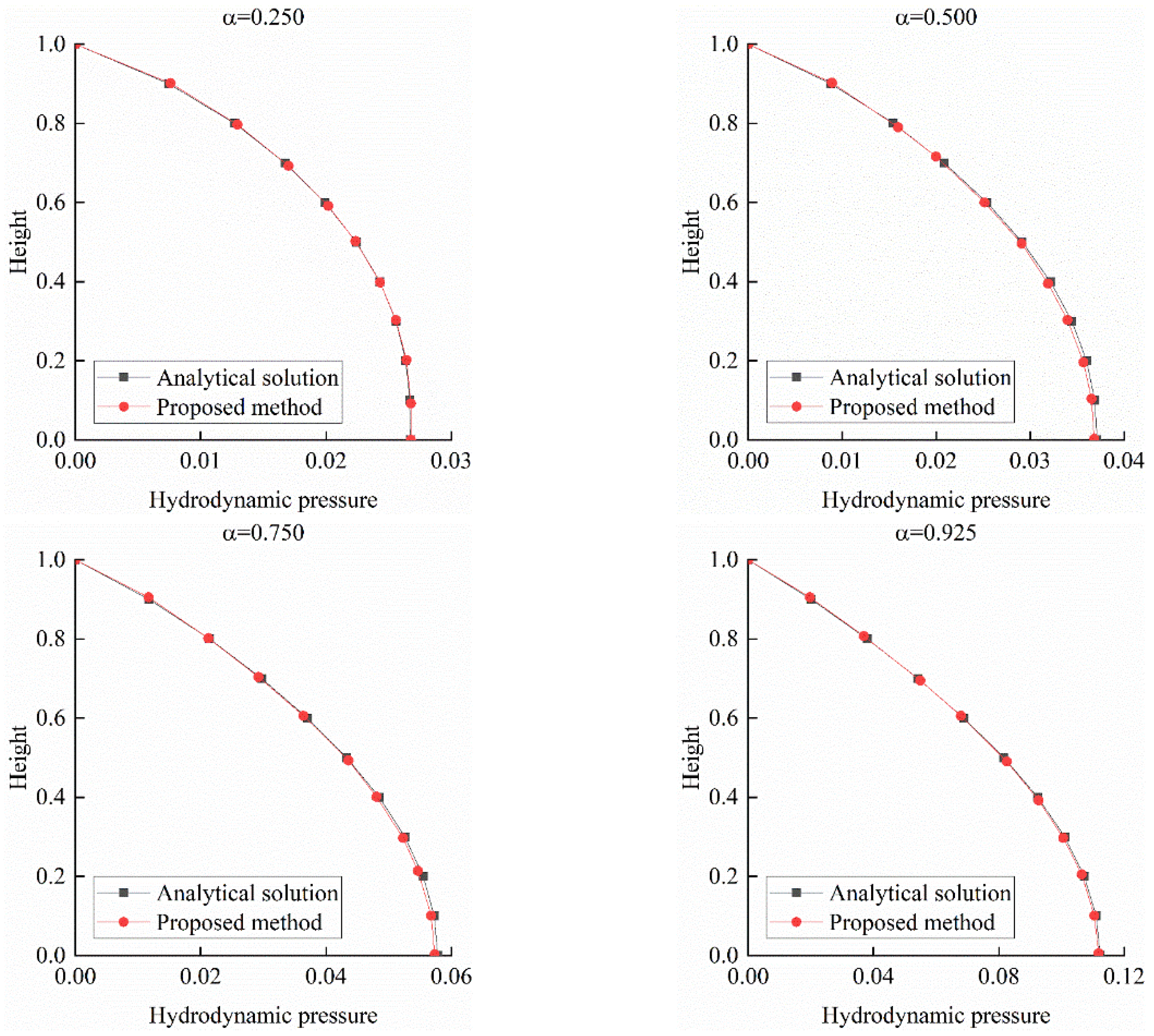
Figure 6.
Hydrodynamic pressure distribution at different frequency.
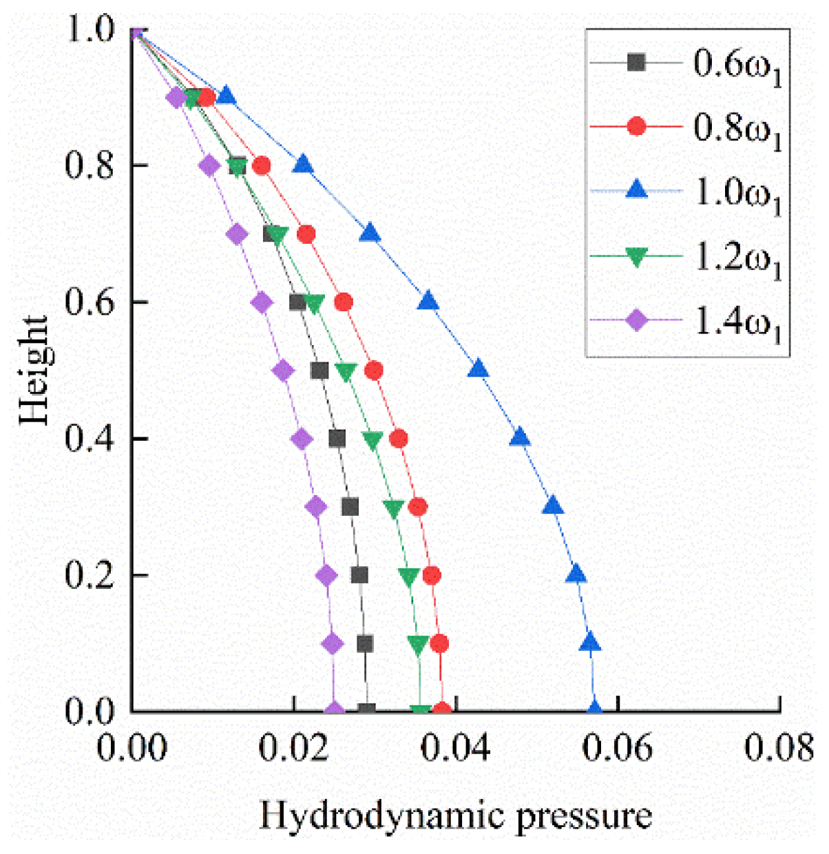
Figure 7.
Frequency response curves for hydrodynamic pressure at upstream dam heel.
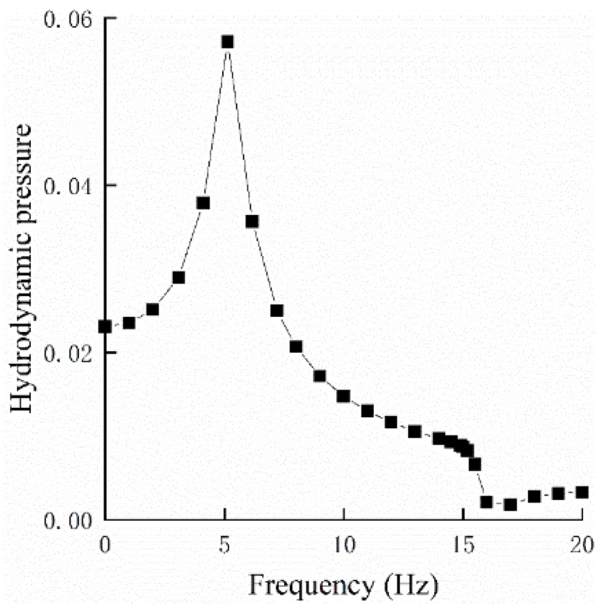
Figure 8.
The history of displacement and acceleration at top of dam.
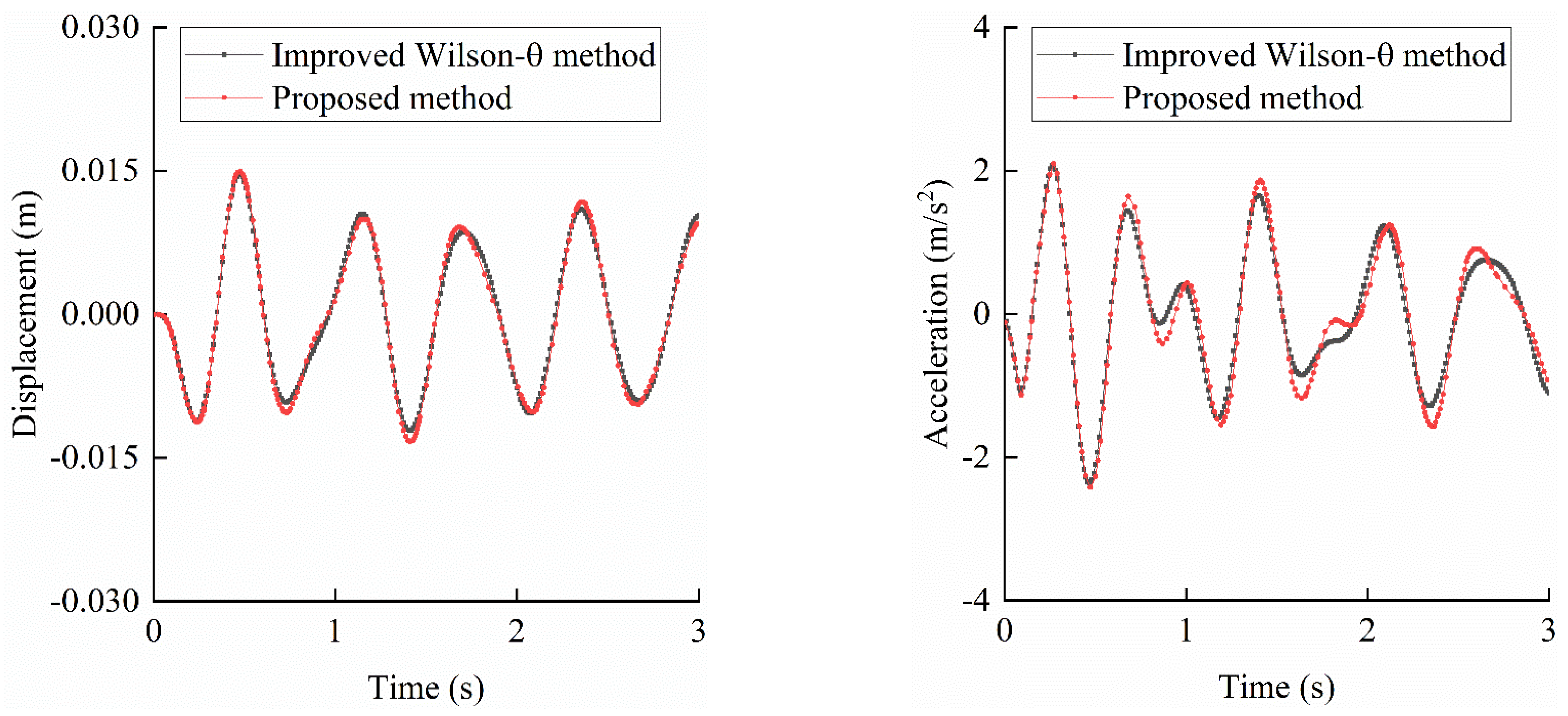
Figure 9.
Impulsive loading.
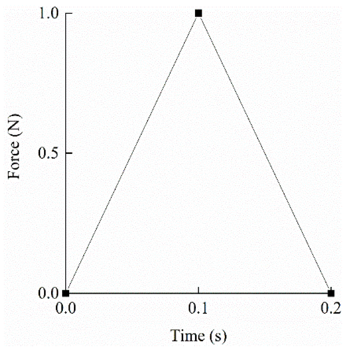
Figure 11.
The SBFE model of semicircular valley.
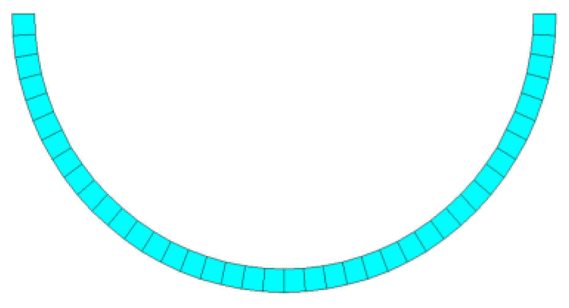
Figure 12.
Comparison of the amplitudes of displacements on the surface of valley.
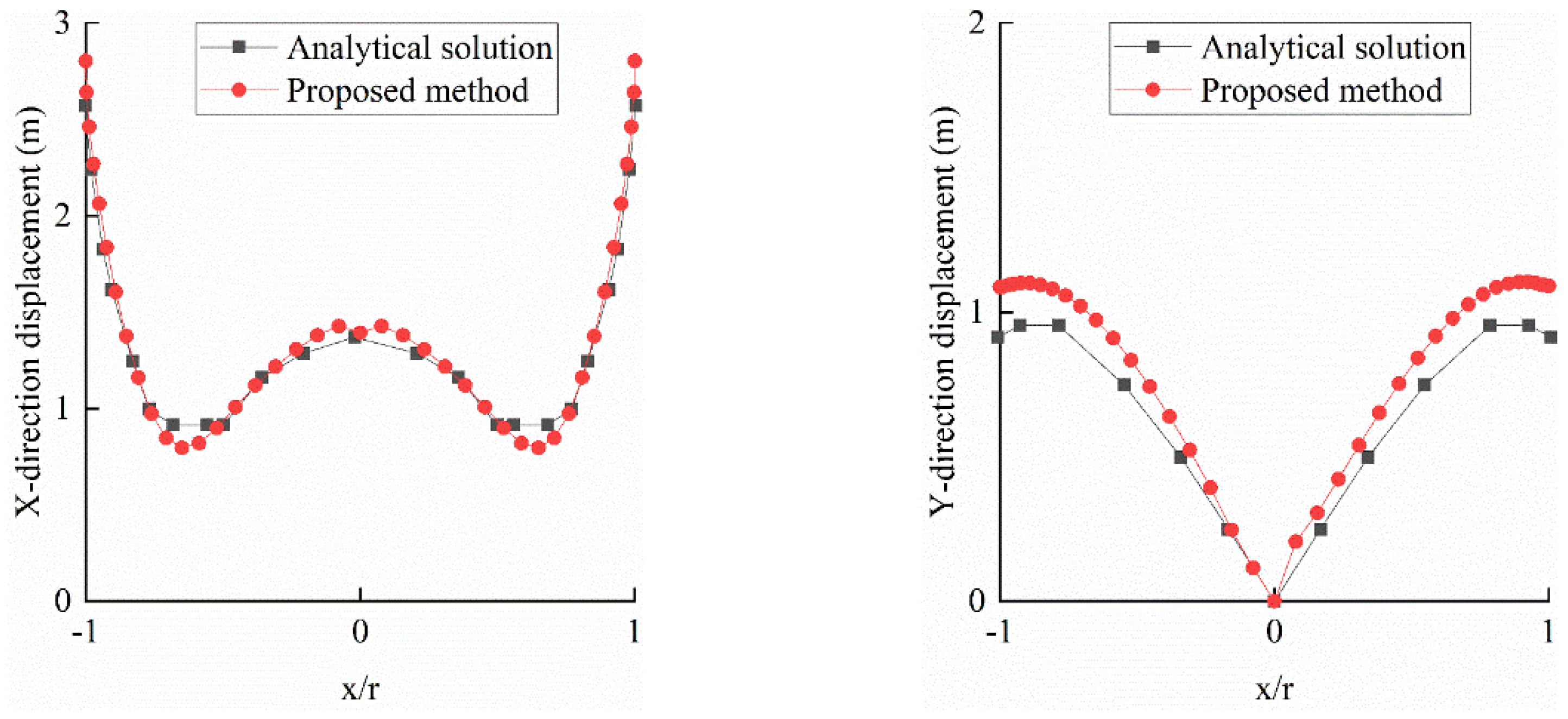
Figure 13.
The history of displacement in X-direction at center and edge of valley.
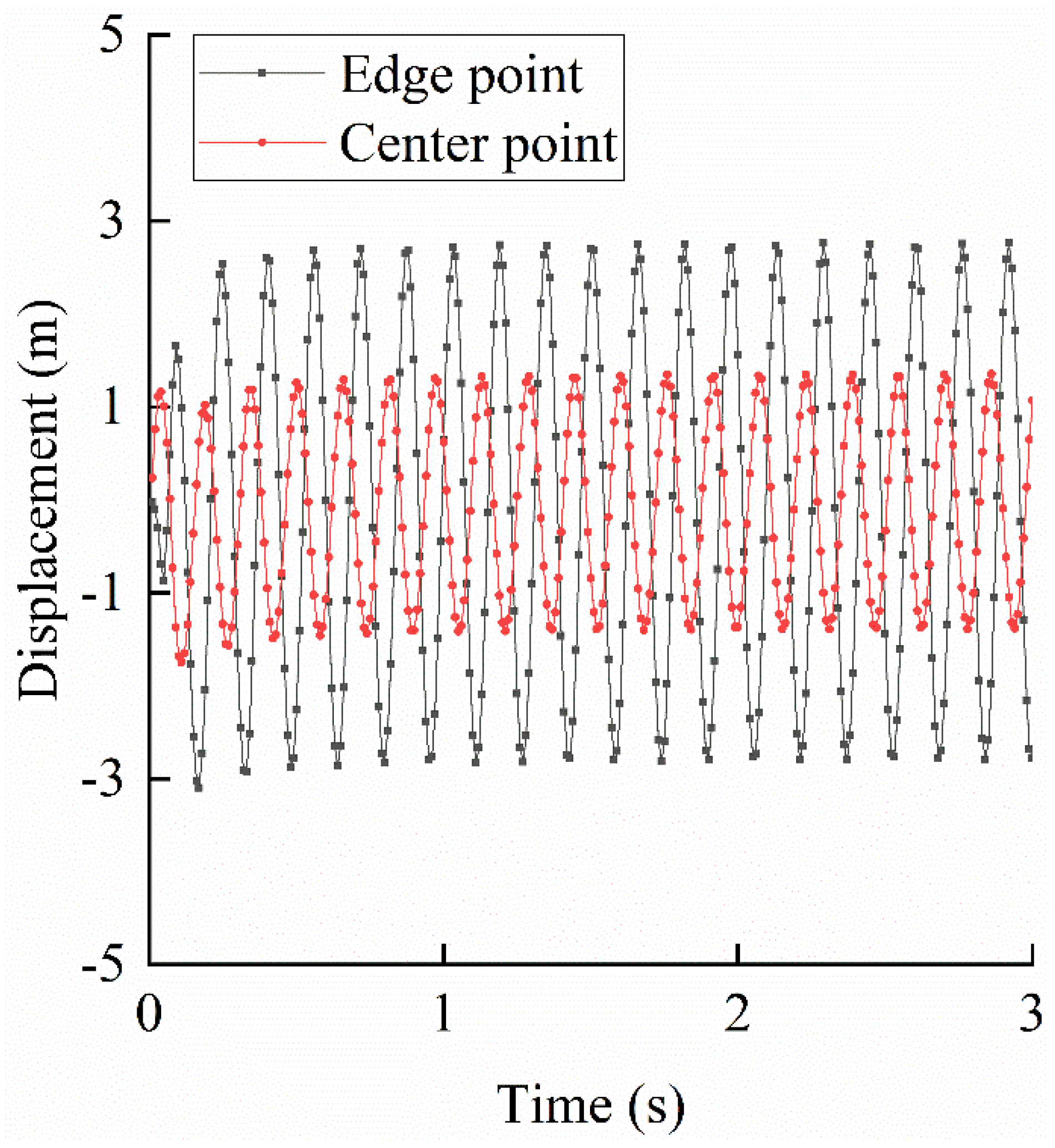

Table 1.
Mechanical properties of the dam concrete used in the numerical model.
| Property | Value | Unit |
|---|---|---|
| Elastic modulus | 28.5 | GPa |
| Poisson’s ratio | 0.167 | – |
| Density | 2400 | kg/m³ |
| Tensile strength | 1.96 | MPa |
| Compressive strength | 17.5 | MPa |
| Dilation coefficient | 0.3 | – |
Table 2.
Comparison of natural frequencies (Hz) using consistent vs. concentrated mass matrices.
| Order | Consistent Mass Matrix | Concentrated Mass Matrix | ||||
|---|---|---|---|---|---|---|
| Proposed Method | FEM | Error | Proposed Method | FEM | Error | |
| 1 | 14.99489 | 14.70902 | 1.94% | 14.93761 | 14.70902 | 1.55% |
| 2 | 34.89665 | 34.2373 | 1.93% | 34.58361 | 34.2373 | 1.01% |
| 3 | 41.53249 | 40.84575 | 1.68% | 41.43663 | 40.84575 | 1.45% |
| 4 | 61.04594 | 59.65121 | 2.34% | 59.87308 | 59.65121 | 0.37% |
| 5 | 89.77952 | 88.08956 | 1.92% | 87.75917 | 88.08956 | 0.38% |
| 6 | 94.48564 | 92.69908 | 1.93% | 92.50532 | 92.69908 | 0.21% |
| 7 | 118.8139 | 117.6998 | 0.95% | 114.4989 | 117.6998 | 2.72% |
| 8 | 123.1543 | 120.2494 | 2.42% | 116.8022 | 120.2494 | 2.87% |
| 9 | 130.9144 | 129.3366 | 1.22% | 125.4198 | 129.3366 | 3.03% |
| 10 | 148.2714 | 144.911 | 2.32% | 135.8962 | 144.911 | 6.22% |
Disclaimer/Publisher’s Note: The statements, opinions and data contained in all publications are solely those of the individual author(s) and contributor(s) and not of MDPI and/or the editor(s). MDPI and/or the editor(s) disclaim responsibility for any injury to people or property resulting from any ideas, methods, instructions or products referred to in the content. |
© 2025 by the authors. Licensee MDPI, Basel, Switzerland. This article is an open access article distributed under the terms and conditions of the Creative Commons Attribution (CC BY) license (http://creativecommons.org/licenses/by/4.0/).
Copyright: This open access article is published under a Creative Commons CC BY 4.0 license, which permit the free download, distribution, and reuse, provided that the author and preprint are cited in any reuse.


