Submitted:
05 May 2025
Posted:
06 May 2025
You are already at the latest version
Abstract
The performance of hydrogen combustion engines can be significantly influ-enced by the geometry of the piston bowl. In this work, various piston bowl designs are explored to assess their effects on thermal load and mixture formation, all while main-taining a constant compression ratio. The engine, originally developed for commercial utility vehicles, has been specifically converted for hydrogen operation to accommodate the specific requirements of this fuel. Abstract piston bowl geometries are modeled and evaluated through Computational Fluid Dynamics (CFD) simulations using the commer-cial software AVL FIRE M. A validated operating point based on a reference piston bowl geometry serves as the basis for comparison. Piston bowl variations with shallower and deeper profiles are investigated to achieve an optimal compromise, leveraging the benefits of each design. Special attention is placed on flow quality and mixture formation when using hydrogen as fuel. Potential adverse effects observed in conventional piston bowl configurations could be mitigated due to hydro-gen’s exceptionally high diffusivity. This characteristic allows overcoming geome-try-induced drawbacks and emphasizes the positive aspects of particular bowl shapes. The study provides a comprehensive understanding of how piston bowl topology influ-ences thermal load, mixture formation, and flow quality in the context of hydrogen com-bustion engines.
Keywords:
SI H2-engine
; flow characteristics
; charge exchange
; H2 combustion
; engine efficiency
1. Introduction
The global transition towards a sustainable and decarbonized energy system is among today's most urgent scientific and technological challenges. While renewable-based electrification expands rapidly, certain sectors such as aviation, maritime transport, and heavy industry, due to their specific demands on energy density and storage, cannot easily switch to direct electric solutions. Consequently, renewable fuels like hydrogen gain increasing attention, offering significant potential for storing renewable electricity and enabling indirect electrification through flexible reconversion technologies ([1,2]).
Internal combustion engines (ICE) utilizing hydrogen as a fuel represent a promising technology pathway to decarbonize these challenging sectors. Hydrogen combustion engines are particularly appealing because they produce primarily water vapor and exhibit high combustion efficiency. However, the high combustion temperatures associated with hydrogen lead to challenges, notably increased nitrogen oxide (NOₓ) formation above temperatures around 1800 K ( [3], p. 495 ff.). Thus, the optimization of hydrogen combustion conditions—particularly mixture formation and in-cylinder charge motion—becomes a key research area.
A crucial factor influencing combustion quality in ICEs is the piston bowl geometry. The piston bowl significantly impacts in-cylinder airflow patterns, such as swirl (rotational motion around the cylinder axis) and tumble (vertical vortex formation), which directly affect mixture homogeneity, combustion stability, and emissions ( [4], p.670). Different design approaches, such as the dynamic adjustment of intake channel geometry or controlled closure of intake valves during partial load operation, have demonstrated the potential to improve combustion efficiency and significantly reduce emissions ( [5], p. 27, [6], p. 299, [7], p.44, 47 f.).
Hydrogen combustion engines particularly benefit from optimized piston bowl geometries due to hydrogen's unique combustion characteristics, notably its extremely high diffusivity and flame speed. While conventional piston bowl designs sometimes induce adverse flow patterns that negatively affect combustion efficiency, the properties of hydrogen could potentially overcome these disadvantages and leverage specific bowl shapes more effectively ([8,9,10,11]). Nonetheless, considerable debate still exists regarding the optimal piston bowl geometry for hydrogen engines, particularly concerning the balance between desirable turbulence and the management of NOₓ formation through temperature control.
This work, therefore, aims to systematically evaluate various piston bowl designs through Computational Fluid Dynamics (CFD) simulations using the AVL FIRE M software. A validated reference operating point, based on a previously tested piston bowl geometry, serves as a comparative benchmark. The principal objectives of the study are to analyze the influence of piston bowl topology on thermal loads, mixture formation quality, and flow behavior, and ultimately identify optimal configurations for hydrogen combustion. Preliminary results indicate that tailored piston bowl geometries significantly enhance mixture preparation and combustion stability, thus reducing NOₓ emissions and improving overall engine efficiency. By providing a deeper understanding of these relationships, this research contributes essential knowledge towards the practical optimization of hydrogen-fueled ICE technology, supporting broader efforts to achieve sustainable and efficient energy systems.
2. Materials and Methods
This research employs numerical simulations validated by experimental data to comprehensively investigate the combustion behavior of hydrogen in a modified internal combustion engine. Simulations were conducted using AVL FIRE M, a commercial CFD software widely used for simulating fluid dynamics, heat transfer, and combustion processes in engine development [12]. The combustion chamber design is adapted from the MAN D38 heavy-duty diesel engine series, conventionally utilized in high-load commercial applications, operating nominally at a speed of n = 1800 rpm [13]. The engine specifications include a cylinder bore radius of rbore = 69 mm, a clearance volume of Vc ≈ 255.87 cm³, and a displacement of Vh ≈ 2542.71 cm³, resulting in a piston stroke of s = 170 mm. Figure 1 shows the adapted combustion chamber design, emphasizing modifications made specifically for hydrogen operation. To enable hydrogen fueling, an injector designed for gaseous fuels was installed alongside a spark plug to provide reliable external ignition. Intake air was managed through a system combining swirl and filling channels, with the design aimed at exploiting variable charge motion strategies to enhance in-cylinder air-fuel mixing. Such strategies are especially important for hydrogen combustion, where achieving an optimal trade-off between mixture homogeneity and local turbulence intensity directly affects efficiency and emissions. Previous studies, such as the investigation by Mahla et al., have demonstrated that enhancing swirl flow intensity in hydrogen-fueled engines significantly improves combustion stability and reduces cyclic variation, ultimately contributing to higher overall efficiency [14]. Additionally, tailored intake designs enabling swirl and tumble motion are particularly advantageous for promoting a homogeneous or slightly stratified charge, depending on the engine's operating conditions [14].
To systematically analyze the influence of piston bowl geometry, simulations were conducted with five different bowl shapes while keeping the compression ratio constant at ε = 11. The reference piston features a lens-shaped bowl with a radius of R = 200 mm. Additional piston designs with radii of R = 125 mm, 150 mm, 250 mm, and 300 mm were created by adjusting the concavity of the piston, thereby altering the bowl volume without changing the compression ratio. Research has shown that changes in piston bowl geometry strongly influence in-cylinder flow structures and turbulence generation, both of which are critical for air-fuel mixing quality and flame propagation dynamics in direct-injected engines. Specifically, tighter bowl designs generally intensify swirl strength, while flatter bowls may promote more uniform tumble motions, each affecting ignition and combustion differently [15].
During the simulations, full engine cycles were calculated over crank angle intervals φ ∈ [158°; 878°] at an operating speed of n = 1500 rpm. Due to variations in piston bowl geometry, slight differences in the top dead center (TDC) position occur; thus, to enable a consistent comparison between different piston designs, flow field planes were defined based on fixed distances from the piston crown, expressed as percentages of the piston stroke rather than fixed crank angles. This allows a geometry-independent evaluation of in-cylinder flow structures across the engine cycle.
The general methodology for analyzing the resulting flow fields involved two main steps. First, the flow distribution along the cylinder’s vertical axis was assessed at various stroke positions to capture the evolution of the large-scale flow structures (see Figure 2, left). Second, to gain deeper insight into the local flow phenomena, a sectional view through the combustion chamber was evaluated, illustrating the interaction between intake air motion, fuel injection, and piston shape (see Figure 2, right). This combined approach enables a comprehensive understanding of the effects of piston bowl variations on mixture formation and subsequent combustion behavior, providing a consistent basis for the results discussed in the following sections.
Efficiency calculation was performed to assess combustion performance for each piston geometry. Hydrogen mass flow was kept constant across simulations, ensuring comparable conditions. The total potential heat release Q was calculated based on the mass of hydrogen (m) and its lower heating value (H), yielding a constant of Q = 8552.66 J energy regarding reference piston. Potential heat release is calculated as follows:
The net gas work WH was determined through numerical integration of the pressure-volume (p-V) diagram generated from the simulation results. Subsequently, the combustion efficiency ηH was calculated as:
The pressure-volume diagram remains a fundamental tool in thermodynamic analysis for evaluating the performance of internal combustion engines, providing insights into losses, compression efficiency, and expansion work. The aim of this study is to evaluate the generated simulation model in the execution of simulations with reference piston. In the most important options and boundary conditions of this CFD model are summarized.

Table 1.
Key simulation model settings and boundary conditions
| Boundary condition | Method | Value |
|---|---|---|
| Engine speed | rpm | 1500 1/min |
| Time steps globally | Angle step | 0.1 °CA |
| Inlet | Pressure | 2.14 bar |
| Exhaust back pressure | Pressure | 1.35 bar |
| Injector inlet | Mass flow | 9 g/s |
| Combustion model | AVL ECFM – 3Z | Spark ignition |
| Stretch factor | 0.425 | |
| Mixing model parameter | 0.5 |
For turbulence modeling, the Reynolds-Averaged Navier–Stokes (RANS) equations were employed, coupled with the κ-ζ-f turbulence model [16]. This model has been proven effective in accurately predicting complex in-cylinder flows characterized by transitional turbulence and wall-bounded layers. For simulating combustion processes, the Extended Coherent Flame Model (ECFM-3Z) was integrated as an additional source term. ECFM-3Z models the flame front as a coherent surface that propagates through turbulent premixed gases, assuming that chemical reactions occur much faster than turbulent mixing processes. This model decouples turbulence effects from chemical kinetics by representing combustion within thin flamelets, depending primarily on local conditions such as pressure, temperature, and equivalence ratio [17]. The use of ECFM-3Z has been validated extensively in the literature, where it has shown to accurately reproduce flame propagation behavior in both spark-ignited and diesel-type combustion engines fueled with hydrogen and hydrocarbon mixtures [18].
Model validation was achieved by comparing simulated cylinder pressure traces to experimental measurements conducted at a defined operating point of 1500 rpm and an indicated mean effective pressure (IMEP) of 13.5 bar. As Schlieren imaging was not feasible due to practical limitations, validation focused on matching the pressure curves. Figure 3 presents the comparison between simulation and experiment, demonstrating strong agreement. Quantitative validation was performed by calculating the Uniformity Index and the Root Mean Square Error (RMSE), yielding values of 0.09% and 4.38%, respectively, which fall well within the accepted margin of <5%.
Mesh generation for the CFD simulations was performed using PolyMesher with standard settings. The use of polyhedral meshes provides notable advantages for complex geometries like combustion chambers, due to their higher numerical accuracy and lower sensitivity to cell stretching compared to tetrahedral meshes. Studies have shown that polyhedral meshes not only improve the fidelity of turbulent flow predictions but also reduce the computational cost by allowing coarser but more accurate discretization of curved surfaces and high-gradient regions [19].
By investigating multiple piston bowl designs, this study aims to clarify the influence of geometric parameters on charge motion, mixture formation, and ultimately combustion efficiency in hydrogen-fueled internal combustion engines. Previous reviews, such as by Verhelst and Wallner, have highlighted the importance of tailored combustion chamber designs for optimizing hydrogen combustion, emphasizing that mixture preparation strategies and geometric control are critical for achieving low NOₓ emissions and high thermal efficiency [20]. Thus, the insight gains from this research are expected to contribute valuable design guidelines for future hydrogen engine developments, enabling cleaner and more efficient use of this versatile energy carrier.
3. Results
Variations in piston bowl geometry influence multiple aspects of hydrogen combustion, particularly regarding charge motion, mixture formation, thermal efficiency, and emissions. The results are presented in a structured sequence to reflect these interdependencies and their cumulative effects. First, in-cylinder charge motion is evaluated to establish the underlying flow conditions relevant for mixture distribution. This is followed by an analysis of efficiency differences between geometries, supported by quantitative calculations. Subsequently, the distribution of critical sub-stoichiometric zones is examined to understand potential implications for ignition stability and pollutant formation. Finally, the raw emissions resulting from each geometry are assessed and compared with model predictions to evaluate the consistency between simulation and physical behavior.
3.1. Charge Motion
The initial part of the analysis focuses on the characterization of in-cylinder swirl flow across all simulated piston bowl geometries, using hydrogen as the injected fuel. The vertical planes, as shown in Figure 2a, were used to analyze the flow field at four equidistant stroke positions (20%, 40%, 60%, 80% of total stroke), enabling a consistent comparison between geometries regardless of small variations in TDC position. These planes are especially suited to detect coherent swirl structures, vortex stabilization, and axial flow intensities relevant for the hydrogen jet's interaction with the ambient air.
Across all five piston geometries, the global swirl pattern remains largely consistent, indicating that the overall intake-induced charge motion is predominantly governed by the swirl channel configuration, which remains unchanged. However, when examining the flow fields in more detail—particularly between piston bowls with extreme geometrical characteristics—subtle but functionally significant differences emerge. For a more detailed and comparative investigation, two geometries were selected as reference cases: a compact piston bowl with a lens radius of R = 125 mm (Figure 4a, left side), and a wider bowl with R = 250 mm (Figure 4b, right side). These geometries represent the lower and upper bounds of the bowl curvature spectrum in this study and enable a focused contrast of their impact on charge motion.
Figure 4, located below, displays the swirl vector fields for both R125 and R250 configurations at three selected crank angles (φ = 590°, 620°, 660°CA) and four vertical positions. The R125 geometry exhibits a more concentrated swirl core, especially during the early compression phase at φ = 590°CA. This swirl center is located near the cylinder axis and retains its coherence across stroke positions, producing elevated axial velocities that persist throughout the compression event. This flow behavior promotes stronger vortex stability and axial momentum, which in turn supports favorable conditions for fuel jet penetration and uniform air-fuel mixing. By contrast, the R250 piston produces a broader, more diffuse swirl pattern. The central region shows lower axial velocities and more radially deflected flow vectors, indicating a diminished capacity to support downward jet motion. While both geometries produce comparable swirl magnitudes at the outer radius, the inner core structure is significantly more dynamic and coherent in the R125 variant.
These observations are particularly relevant because axial swirl intensity and vortex stability directly affect how the hydrogen jet interacts with the ambient air during and after injection. A strong central swirl can enhance the breakup and mixing of the hydrogen jet, increasing the potential for homogeneity and avoiding local stratification. This effect is further amplified by the reduced density and high diffusivity of hydrogen, which allows for rapid transport along axial flow vectors—provided such structures are present and stable. The R250 bowl, despite its larger volume and surface area, fails to generate comparable axial support, which limits the hydrogen’s ability to reach deeper regions of the combustion chamber.
To better assess how these flow characteristics influence fuel distribution, the corresponding sectional planes through the combustion chamber—defined in Figure 2b—were used to visualize the interaction between airflow and hydrogen injection. Figure 5, shown on the following page, presents the flow vectors and hydrogen mass fraction for all piston geometries at φ = 565°CA and φ = 590°CA, two key crank angles during and shortly after injection.
The difference in jet penetration between geometries becomes clearly visible in Figure 5. The R125 geometry generates a narrow, vertically oriented hydrogen jet that penetrates deeply into the combustion chamber, supported by the stronger axial flow discussed previously. At φ = 565°CA, the leading edge of the fuel plume already reaches mid-chamber height, and by φ = 590°CA, it extends close to the piston surface. This deep penetration promotes a more uniform axial fuel distribution, potentially improving combustion initiation and reducing local lean zones. Conversely, in the R250 case, the jet bends laterally soon after injection, indicating insufficient axial flow guidance. As a result, the hydrogen remains concentrated in the upper half of the chamber, with limited mixing along the vertical axis.
By examining the distribution later in the injection process, these tendencies become even more apparent: the late-phase snapshots at φ = 590°CA confirm that only the R125 and, to a lesser extent, the R150 and R200 geometries achieve a sufficiently broad fuel spread over the full vertical chamber height. This vertical coverage is critical, as it determines whether the mixture is ignition-relevant throughout the entire chamber volume—a prerequisite for stable combustion and consistent power output.
Taken together, these findings point toward a clear structural influence of the piston bowl geometry: specifically, the curvature radius and bowl depth shape the axial charge motion, which in turn governs the behavior of the hydrogen jet and its degree of stratification. A strong, coherent swirl core with axial components—as established in the R125 configuration—not only improves the efficiency of fuel–air mixing, but also reduces the risk of stratification-induced instabilities. In contrast, flatter or broader bowl shapes tend to weaken these effects and lead to less favorable mixing outcomes.
3.2. Efficiency
The preparation of the data for evaluating efficiency involved multiple validation steps to ensure that the pressure–volume (PV) data computed by AVL FIRE were suitable for constructing reliable high-pressure loops. These loops are essential for assessing thermodynamic performance through the application of Equations (1) and (2) outlined in the Materials and Methods section. Initially, the raw outputs from AVL FIRE were transferred into MATLAB, where volume and absolute-pressure datasets were plotted to assess consistency across all piston bowl geometries.
Upon initial inspection, it became apparent that certain segments of the PV diagrams, specifically those corresponding to the gas exchange processes, exhibited atypical shapes. This anomaly was primarily due to the simulation domain encompassing portions of the intake and exhaust channels, which resulted in data points representing external conditions rather than closed combustion chamber states. Consequently, only the high-pressure portion of the cycle—where both intake and exhaust valves remain closed—was selected for subsequent efficiency evaluations. To achieve this, all data points corresponding to valve overlap phases were systematically removed.
Additionally, it was recognized that each simulation ran over a single engine cycle only, without cyclic boundary conditions. As a result, a small discontinuity between the end and beginning of the PV curve appeared, manifesting as a minor gap when the raw data were plotted. In practical multi-cycle simulations or real engine operation, this discontinuity would not occur. To correct this artifact and achieve a closed PV loop necessary for accurate work integration, the initial pressure and volume conditions were appended at the end of each dataset.
Further adjustments were necessary in the specific case of the piston bowl geometry with a lens radius of R = 200 mm. Here, missing pressure-volume coordinates near the end of the expansion phase resulted in an incomplete high-pressure loop. To mitigate this, the missing points were substituted with corresponding data from the R = 250 mm hydrogen simulation. The substitution is justified by the remarkable similarity in expansion behavior between the R = 200 mm and R = 250 mm cases, particularly during the late expansion stroke, ensuring minimal error introduction. This correction can be visually validated in Figure 6, where the high-pressure loops across all geometries exhibit consistent trends during the expansion phase.
Figure 6 highlights the profound impact of piston bowl geometry on the compression characteristics and the maximum in-cylinder pressures achieved. Specifically, the R125 bowl exhibits the steepest pressure rise and highest peak pressure, followed sequentially by R150 and R200. The R300 configuration, in contrast, demonstrates the flattest pressure curve and the lowest peak pressure, suggesting suboptimal conditions for hydrogen combustion efficiency under the tested operating point.
These geometric effects are amplified by the distinct thermodynamic properties of hydrogen as a fuel. Hydrogen's low compressibility compared to hydrocarbon fuels means that the compression process results in sharper pressure increases as the piston approaches top dead center (TDC). Additionally, hydrogen’s high thermal conductivity accelerates post-combustion cooling processes [21], The effect of water vapor, a primary product of hydrogen combustion, further enhances the cooling during the expansion stroke due to its large specific heat capacity [8,22].
The resulting pressure dynamics do not merely affect temperature behavior but directly determine the mechanical work that can be extracted from the cycle. Specifically, the steepness of the compression curve and the magnitude of the peak pressure define the area enclosed in the PV loop, which represents the gas work WH. This work increases with sharper pressure gradients and higher combustion completeness—conditions typically favored by geometries that promote efficient charge motion and rapid flame development.
It is important to highlight that hydrogen, compared to conventional hydrocarbon fuels, exhibits an extraordinarily wide flammability range, supporting combustion at equivalence ratios up to λ ≈ 10 ( [2], p. 203). Consequently, hydrogen tolerates a leaner mixture while still remaining combustible. Previous investigations have indicated that, through suitable piston bowl geometries and the corresponding influence on charge motion, hydrogen tends to form advantageous fuel clouds around the spark plug when using lens radii of R = 125 mm or R = 300 mm.
Figure 8 reinforces this conclusion: among the examined variants, R125 exhibits not only the steepest pressure rise and the highest peak pressure during the combustion phase but also the most favorable hydrogen distribution near the spark plug at ignition timing (φ = 709 °CA). The contour plot reveals a concentrated and symmetrically placed hydrogen-rich region in the central upper part of the combustion chamber, closely surrounding the ignition site. This localized enrichment fosters rapid kernel formation and robust flame propagation.
In contrast, the R300 and R250 variants show more diffuse hydrogen distributions, with leaner zones near the spark plug and displaced rich regions toward the periphery. These characteristics are visible both in the color gradients and in the numerical λ-range values provided alongside the figure. Particularly for R150, the extremely wide span from λ = 0.64 to 106.22 indicates pronounced inhomogeneity, which may destabilize ignition and slow down early combustion.
The tabulated equivalence ratio extremes in the figure further supports these observations. R125 maintains a narrow λ-range with moderate deviation, suggesting more homogeneous mixing in the spark vicinity. Such distribution characteristics are desirable in direct-injected hydrogen engines, where lean misfire limits and incomplete combustion must be avoided. The spatial positioning of hydrogen around the intake valves and central spark plug demonstrates how piston bowl geometry directly governs the three-dimensional mixture stratification at ignition-relevant conditions.
The pressure development in the combustion phase for each geometry is summarized in Figure 9, where the combustion-specific portion of the high-pressure loop clearly illustrates the delay and flattening in pressure rise for the wider bowl variants. These findings directly link mixture distribution at ignition timing to subsequent thermodynamic performance.
In particular, the R125 configuration shows a noticeably steeper pressure rise immediately after ignition, resulting from the more concentrated hydrogen cloud around the spark plug. This promotes faster flame kernel formation and more rapid heat release compared to the wider bowl designs. In contrast, the R250 and R300 configurations demonstrate a visibly flatter pressure curve, indicating a slower combustion progression likely due to leaner local mixtures and delayed flame development.
Such differences are critical because the steepness of the pressure rise is directly connected to the rate of energy release during the combustion phase. A rapid pressure increase suggests that a large portion of the chemical energy is converted into thermal and mechanical work within a short crank angle window, thereby enhancing cycle efficiency. Conversely, a more gradual pressure rise spreads the combustion over a larger crank angle interval, which can reduce peak pressures and lead to less favorable work extraction during expansion.
3.2.1. Efficiency calculation
In the present study, the hydrogen mass flow was kept constant across all simulated piston bowl geometries by applying an identical injector mass flow within the simulation environment. This parameter consistency allowed for a geometry-based comparison of conversion efficiency, without introducing additional thermodynamic variables. The efficiency analysis is based on the gas work WH, obtained by integrating the high-pressure loop of each pressure–volume (PV) diagram. The methodology follows the thermodynamic definitions given by Equations (1) and (2) in the Materials and Methods section.
The results are summarized in Table 2 and Table 3, which document the computed work values and corresponding efficiencies for each piston geometry. As anticipated from the pressure trace analysis, the configurations with steeper pressure gradients—particularly R125 and R150—produced the highest gas work output. These geometries support faster flame propagation and more favorable expansion characteristics, thereby enhancing thermodynamic performance. In contrast, the R300 configuration consistently yielded the lowest efficiency due to a slower combustion process and more dispersed hydrogen distribution.
Here, WH is the gas work obtained from the high-pressure portion of the engine cycle, and Q represents the potential heat for the injected hydrogen. The efficiency results are presented analog to Table 2 in Table 3.
Figure 9 illustrates the combustion-specific section of the PV diagrams and reveals the differences in pressure evolution between bowl designs. The R125 variant exhibits the most rapid pressure rise and highest peak pressure, which translates directly into increased mechanical work. R150 and R200 follow closely, while R250 begins to show signs of delayed combustion, and R300 trails with significantly lower pressure buildup. The trend correlates with earlier findings from mixture distribution and charge motion, underscoring the influence of geometry on flame speed and combustion timing.
These observations further validate the robustness of the simulation approach. The uniform simulation settings and careful PV data treatment ensure reliable work integration and isolate the geometric impact. The fact that pressure development trends and gas work results converge across independent metrics reinforces the internal consistency of the CFD methodology and builds confidence in its predictive capability.
Additionally, the R125 geometry benefits not only from optimal flame development but also from its ability to channel hydrogen into ignition-relevant regions early in the compression stroke. This localized fuel availability enhances pre-ignition stratification in the spark plug vicinity, supporting rapid energy release immediately after ignition. Such effects are clearly evident when comparing flame surface density and local equivalence ratio plots across geometries, which are discussed in the following section. Ultimately, this makes R125 the most efficient geometry among the configurations tested, offering a favorable balance between stratification, turbulence, and thermal efficiency.
3.4. Critical sub-stoichiometry
The evaluation of combustion dynamics revealed that several geometries—particularly those with broader piston bowls—were susceptible to the formation of locally sub-stoichiometric zones at ignition timing. These are regions where the local air–fuel equivalence ratio λ exceeds the optimal range for complete combustion. Although hydrogen offers a wide flammability spectrum, lean mixtures with limited hydrogen concentration may delay flame propagation or suppress ignition altogether.
Figure 10 visualizes the location and effect of such sub-stoichiometric zones. The left portion of the figure shows lean regions (λ ≥ 1.01) shortly before ignition at φ = 709 °CA. The central image contrasts this by highlighting areas below stoichiometry (λ ≤ 1), while the right side depicts the corresponding flame surface density (FSD) shortly after ignition at φ = 730 °CA. It becomes evident that fuel-rich and fuel-lean regions are highly geometry-dependent. Specifically, in the R300 and R250 configurations, unburned hydrogen remains concentrated along the bowl edge due to delayed flame access and insufficient radial mixing.
The sub-stoichiometric zones referenced in Table 4 can be directly linked to geometric features of the combustion chamber. Sharp transitions and bowl edges hinder the flow, forming so-called vortex or “dead” zones[23], which disrupt local air–fuel mixing and lead to persistent stratification. As a result, it is challenging to fully eliminate such regions through piston design alone. Most of the simulated configurations exhibit some degree of local sub-stoichiometry. For instance, the R125 piston shows minor lean regions near the inlet valve, while the reference geometry R200 reveals stratification around the fire step area.
Beyond their thermodynamic implications, these locally unreacted fuel zones also pose mechanical risks—particularly when they form near chamber walls. High hydrogen concentrations in proximity to the cylinder liner, especially in the top-land region, can displace the protective oil film and increase localized thermal stress. This condition accelerates wear on piston rings and cylinder surfaces and may reduce the long-term durability of key components. Although such effects might be tolerable under transient conditions like cold starts, they raise concerns when persistent, especially under steady-state loads. It should be noted that the simulations in this study were limited to a single engine cycle and do not capture long-term degradation.
Unlike conventional hydrocarbon fuels, hydrogen provides no lubricating function and exhibits a combination of properties—namely, high diffusivity and low quenching distance—that amplify its interaction with solid surfaces [24,25]. When hydrogen-rich zones persist near thermal boundaries, they may therefore increase the likelihood of local material degradation through thermal fatigue and oil-film destabilization.
All simulations were conducted using the Reynolds-Averaged Navier-Stokes (RANS) turbulence model, widely adopted in industrial CFD applications. While robust and computationally efficient, RANS do not resolve all turbulence scales, potentially limiting the accuracy of local mixing predictions.
3.5. Raw Emissions
Building on the sub-stoichiometric analysis, the following section addresses the formation of raw emissions, focusing exclusively on nitric oxide (NO) in the context of hydrogen combustion. The CFD simulation results are used to assess NO formation for all piston bowl geometries at the end of the engine cycle (φ = 878 °CA), just before the exhaust valve opens. This crank angle was selected to capture the full scope of in-cylinder NO development without being affected by post-combustion exhaust processes.
The simulation employs the extended Zeldovich mechanism to calculate NO, accounting for the primary temperature-dependent reactions between nitrogen (N₂), oxygen (O₂), and intermediate species like atomic oxygen and nitrogen. These are derived from local thermodynamic equilibrium conditions embedded within the combustion model. The results are summarized in Table 5, presenting both mass fraction (ppm) and the absolute NO mass (mg) for each piston configuration.
A direct comparison to measured NOₓ emissions is presented in Table 4, though it must be emphasized that the test bench measurements refer to total NOₓ, while the simulation captures only NO. Furthermore, real-world NOₓ values are temporally and spatially averaged within the exhaust system and affected by mixing, quenching, and secondary reactions. Nonetheless, simulation results reflect peak in-cylinder conditions and thus reveal reliable trends for comparative evaluation across geometries.
As evident from the simulation, the reference case (R200) exhibits a peak NO mass fraction of 548 ppm, which is nearly double the measured NOₓ value of 250 ppm. The highest simulated NO formation occurs in the R125 configuration with 1194 ppm (7.4 mg), while the lowest is seen in the R250 variant with 327 ppm (2.02 mg). This indicates a strong dependency of NO formation on piston bowl geometry, driven by differences in flame propagation, mixture stratification, and local temperature evolution.
Figure 11 visualizes the evolution of NO mass fraction across crank angle for each geometry. All configurations follow a similar pattern: a sharp increase after ignition, followed by stabilization. Notably, R125 reaches its peak NO level earliest and sustains it throughout the expansion phase. R300, on the other hand, demonstrates a slower buildup but stabilizes at a moderately high level, suggesting sustained post-flame temperatures due to slower mixing and longer combustion duration.
The strong NO rise seen in R125, despite its high combustion efficiency, can be attributed to early and intense heat release, as confirmed by the pressure curves in Figure 6 and flame development in Figure 8. Rapid combustion increases peak flame temperature, thus accelerating the Zeldovich reactions. While this may benefit pressure development and thermal efficiency, it also enhances thermal NO formation.
According to [3] (p. 495 ff.), about 90–95% of NO emissions in piston engines arise from thermal NO mechanisms. Hence, higher in-cylinder temperatures generally lead to an increase in NO production—provided those elevated temperatures persist long enough for the formation reactions to proceed. A This connection is particularly evident in the average in-cylinder temperature curve shown in Figure 12, where a peak temperature of ~1650–1700 K is reached shortly after ignition. Although this is slightly below the 1800 K threshold cited for peak thermal NO production, it must be considered that local flame front temperatures can exceed the cylinder-averaged values. Therefore, even if the bulk temperature appears marginal, localized hot spots within the flame region can promote high NO formation in narrow piston bowl designs like R125. Hydrogen combustion inherently promotes higher flame temperatures due to its high flame speed and adiabatic combustion temperature. However, a key mitigating factor in hydrogen engines is the post-flame cooling effect caused by water vapor formation. Water’s large heat capacity facilitates more efficient heat removal from the combustion chamber, thereby limiting the overall amount of thermal NO formed [8,22].
Small differences in mixture formation and flame propagation can nonetheless cause variations in peak combustion temperature, as well as in how quickly temperatures decline after ignition. For instance, a piston bowl design that promotes thorough mixing without unduly prolonging the peak temperature region may strike a favorable balance between complete combustion and minimal NO generation. At the same time, overly strong swirl or late-burning zones could cause localized temperature spikes, driving up NO in specific regions.
4. Discussion
The results presented across Section 3.1 to Section 3.5 confirm that piston bowl geometry exerts a significant influence on hydrogen combustion behavior in terms of in-cylinder flow, mixture stratification, combustion efficiency, and pollutant formation. From a thermodynamic and fluid mechanical standpoint, these findings highlight key interdependencies between geometric design parameters and local flow fields, particularly swirl intensity and axial momentum development.
In line with expectations, compact piston bowls—especially the R125 configuration—enable more stable and focused central swirl structures. These enhance axial flow velocities, which in turn improve fuel jet penetration and vertical mixture distribution. The deep and stable vortex core formed in R125 ensures that injected hydrogen is guided into the combustion chamber in a coherent and well-distributed pattern, reducing mixture stratification and supporting faster flame kernel development. These observations are consistent with previous work on swirl-supported direct injection systems, which emphasize the importance of axial swirl for enhancing fuel–air mixing and ignition stability.
However, the downside of stronger swirl and steeper combustion gradients, as observed in R125, is the elevated risk of increased thermal NO formation. The simulation results confirm that the early and intense combustion phase in this configuration leads to rapid heat release and high local flame front temperatures. According to the extended Zeldovich mechanism, thermal NO formation is highly sensitive to both peak temperature and residence time. While the average in-cylinder temperatures remain below the threshold of 1800 K, localized regions near the flame front may temporarily exceed this value, triggering enhanced NO generation. This is a well-known phenomenon in high-efficiency hydrogen combustion and corroborated by classic studies such as those by Heywood [20], and more recent findings on hydrogen-specific emission behavior [8].
The mitigating effect of post-flame cooling, primarily due to the high specific heat capacity of water vapor, is evident but not always sufficient to suppress NO formation completely in aggressive combustion setups. This highlights a fundamental trade-off between maximizing thermal efficiency and minimizing pollutant emissions. Optimized combustion strategies, such as staged injection or variable charge motion, may help balance these competing priorities.
In contrast, broader piston bowls (e.g., R250 and R300) reduce peak temperature gradients and limit NO formation but at the cost of slower combustion and reduced thermal efficiency. These geometries are more prone to the formation of sub-stoichiometric zones, particularly near the piston crown edge and fire step. Such zones, if persistent, can impair flame propagation and increase the risk of incomplete combustion. The observed stratification patterns in R250 and R300 highlight the importance of geometric transitions and local vortex dynamics in mixture preparation. Literature on stratified charge combustion supports the view that recirculation zones near sharp geometrical features promote fuel stagnation and mixing deficits [23].
In terms of mechanical durability, localized fuel-rich or sub-stoichiometric zones near the cylinder wall may also pose challenges. High hydrogen concentrations in such areas can displace lubricating oil films and expose metal surfaces to high thermal loads. This effect, which is particularly critical under cold-start conditions or transient load changes, can accelerate wear and reduce engine life. Studies on hydrogen’s poor lubricity and high diffusivity confirm this risk [24,25].
Regarding modeling accuracy, the use of a Reynolds-Averaged Navier–Stokes (RANS) turbulence model introduces certain limitations. While effective for predicting global flow structures, RANS may underpredict localized turbulence and mixing effects, especially in zones near the jet or at sharp geometrical transitions. This could affect the accuracy of predicted sub-stoichiometric distributions and local temperature spikes. Future work should therefore consider higher-resolution methods such as Large Eddy Simulation (LES) or hybrid RANS–LES approaches to improve the fidelity of mixture preparation and emission prediction [26].
Finally, the current study was limited to single-cycle simulations at a fixed operating point. While this provides valuable insight into geometric effects under steady-state conditions, multi-cycle simulations and experimental validation under varied load and speed conditions are essential to generalize these findings. Further investigation should also explore geometry-adaptive piston bowls, real-time control of charge motion, and hydrogen-specific injection strategies as potential pathways to balance efficiency, emissions, and mechanical durability in future hydrogen engine designs.
5. Conclusions
Analysis of the charge motion has shown that the swirl flow determined by the swirl-channel geometry emerges in all investigated piston-bowl configurations for hydrogen, as was anticipated. Differences arise primarily in the velocity magnitudes and the positions of the swirl centers, yet the overall flow directions are largely similar—particularly from about 100 °CA before top dead center, where the flow fields exhibit minimal variation.
As stated in the Results – Charge motion section, that the mixture formation and flow characteristics at φ = 565 °CA along the cylinder’s longitudinal axis strongly influence the fuel distribution at the ignition timing (φ = 709 °CA). For the hydrogen-fueled engine considered here, the same cross-sectional plane proved decisive: only a few configurations achieved an advantageous hydrogen distribution at the spark plug. This outcome suggests that, at the investigated speed of n = 1500 rpm, implementing a variable control of charge motion—such as a flap in the filling channel—may be necessary to ensure a desirable mixture formation. The results regarding combustion behavior, as well as the corresponding efficiency and gas work obtained from the high-pressure loop, confirm that optimal performance is closely tied to the presence of a well-defined hydrogen cloud around the spark plug at ignition. When this localized enrichment occurs, higher peak pressures, greater induced work, and improved efficiency typically follow. Conversely, insufficient hydrogen near the spark plug tends to slow the combustion reaction and diminish the achievable pressure rise.
However, systems specifically optimized for hydrogen combustion remain limited and can be costly. In many cases, upgrading existing machinery entails securing suitable components and reevaluating engine parameters to accommodate hydrogen’s unique chemical and physical properties. Given that projects must be adapted to their specific conditions, further work is required to develop robust, widely applicable guidelines for hydrogen-engine conversions.
Abbreviations
The following abbreviations are used in this manuscript:
| CFD | Computational Fluid Dynamics |
| FSD | Flame Surface Density |
| ICE | Internal Combustion Engine |
| IMEP | Indicated Mean Effective Pressure |
| LES | Large Eddy Simulation |
| NO | Nitric Oxide |
| NOx | Nitrogen Oxides |
| PV | Pressure–Volume |
| RANS | Reynolds-Averaged Navier–Stokes |
| TDC | Top Dead Center |
| WH | Gas Work (thermodynamic work from PV loop) |
| ηH | Combustion Efficiency |
| λ (lambda) | Air–Fuel Ratio |
| φ (phi) | Crank Angle [°CA] |
References
- Burger, Bruno Prof., Dr. Column charts on electricity generation | Energy-Charts. Available online: https://www.energy-charts.info/charts/energy/chart.htm?l=en&c=DE&chartColumnSorting=default&interval=year&year=-1&sum=1&legendItems=4x061ie (accessed on 17 January 2025).
- Klell, M.; Eichlseder, H.; Trattner, A. Wasserstoff in der Fahrzeugtechnik: Erzeugung, Speicherung, Anwendung; 4., aktualisierte und erweiterte Auflage; Springer Vieweg: Wiesbaden, 2018; ISBN 9783658204471. [Google Scholar]
- Merker, G.P. Grundlagen Verbrennungsmotoren: Funktionsweise, Simulation, Messtechnik, 7th ed.; Springer Fachmedien Wiesbaden GmbH: Wiesbaden, 2014; ISBN 9783658031954. [Google Scholar]
- Grundlagen Verbrennungsmotoren: Funktionsweise und alternative Antriebssysteme : Verbrennung, Messtechnik und Simulation; Merker, G.P., Teichmann, R., Eds.; 9., korrigierte Auflage; Springer Fachmedien Wiesbaden: Wiesbaden, 2019; ISBN 9783658235574. [Google Scholar]
- Neubert, V.M. Experimentelle Untersuchung der Brennraumströmung eines Zweiventil-Dieselmotors.
- Reif, K. Dieselmotor-Management: Systeme, Komponenten, Steuerung und Regelung, 6th ed.; Springer Vieweg. in Springer Fachmedien Wiesbaden GmbH: Wiesbaden, 2020; ISBN 9783658250720. [Google Scholar]
- Ottomotor mit Direkteinspritzung und Direkteinblasung: Ottokraftstoffe, Erdgas, Methan, Wasserstoff; van Basshuysen, R., Ed.; 4. Aufl. 2017; Springer Fachmedien Wiesbaden: Wiesbaden, 2017; ISBN 9783658122157. [Google Scholar]
- Flammentemperatur. Available online: https://www.chemie.de/lexikon/Flammentemperatur.html (accessed on 2 February 2025).
- Stickoxide. Available online: https://www.chemie.de/lexikon/Stickoxide.html (accessed on 2 February 2025).
- Michael Schrank; Vivien Langer; Benjamin Jacobsen; Thomas von Unwerth. NOW_Metastudie_Wasserstoff-Verbrennungsmotor.
- Lohninger, H. Stickstoffmonoxid. Available online: http://anorganik.chemie.vias.org/stickstoffmonoxid.html (accessed on 2 February 2025).
- AVL FIRE M; AVL. 2025.
- MAN D3876 für Lkw, Baumaschinen und Landtechnik-Anwendungen | MAN Engines. Available online: https://www.man.eu/engines/de/produkte/off-road/man-d3876-fuer-lkw-baumaschinen-und-landtechnik-anwendungen.html (accessed on 2 February 2025).
- Gürbüz, H.; Akçay, İ.H.; Buran, D. An investigation on effect of in-cylinder swirl flow on performance, combustion and cyclic variations in hydrogen fuelled spark ignition engine. Journal of the Energy Institute 2014, 87, 1–10. [Google Scholar] [CrossRef]
- Xu, L.; Bai, X.-S.; Li, Y.; Treacy, M.; Li, C.; Tunestål, P.; Tunér, M.; Lu, X. Effect of piston bowl geometry and compression ratio on in-cylinder combustion and engine performance in a gasoline direct-injection compression ignition engine under different injection conditions. Applied Energy 2020, 280, 115920. [Google Scholar] [CrossRef]
- Durbin, P.A. Near-wall turbulence closure modeling without “damping functions”. Theoret. Comput. Fluid Dynamics 1991, 3, 1–13. [Google Scholar] [CrossRef]
- Colin, O.; Benkenida, A. The 3-Zones Extended Coherent Flame Model (Ecfm3z) for Computing Premixed/Diffusion Combustion. Oil & Gas Science and Technology - Rev. IFP 2004, 59, 593–609. [Google Scholar] [CrossRef]
- Özbilen, Ş.K.; Kaleli, E.H.; Aydar, E. Numerical investigation of combustion characteristics of extended coherent flame model 3 zones (ECFM-3Z) in diesel engines running with biodiesel. Env Prog and Sustain Energy 2024, 43. [Google Scholar] [CrossRef]
- Sosnowski, M.; Krzywanski, J.; Grabowska, K.; Gnatowska, R. Polyhedral meshing in numerical analysis of conjugate heat transfer. EPJ Web Conf. 2018, 180, 2096. [Google Scholar] [CrossRef]
- Verhelst, S.; Wallner, T. Hydrogen-fueled internal combustion engines. Progress in Energy and Combustion Science 2009, 35, 490–527. [Google Scholar] [CrossRef]
- Schweizer-fn. Wärmeleitfähigkeit von Gasen. Available online: https://www.schweizer-fn.de/stoff/wleit_gase/wleit_gase.php (accessed on 2 February 2025).
- Spezifische_Wärmekapazität. Available online: https://www.chemie.de/lexikon/Spezifische_W%C3%A4rmekapazit%C3%A4t.html (accessed on 2 February 2025).
- Grenzschichtablösung (Strömungsabriss) | tec-science. Available online: https://www.tec-science.com/de/mechanik/gase-und-fluessigkeiten/grenzschichtablosung-stromungsabriss/ (accessed on 2 February 2025).
- Abdichtprobleme und Kolbenringschäden | MS Motorservice Deutschland. Available online: https://www.ms-motorservice.com/de/de/technipedia/abdichtprobleme-und-kolbenringschaeden-898 (accessed on 2 February 2025).
- Insight: Die Herausforderungen beim Wasserstoffverbrennungsmotor (2/3). Motorsport-Total.com [Online], March 10, 2024. Available online: https://www.motorsport-total.com/24-stunden-von-le-mans/news/insight-die-herausforderungen-beim-wasserstoffverbrennungsmotor-23-24031001 (accessed on 2 February 2025).
- gestione. Turbulence models in CFD. Idealsimulations [Online], August 31, 2019. Available online: https://www.idealsimulations.com/resources/turbulence-models-in-cfd/ (accessed on 2 February 2025).
Figure 1.
Cross-section of the combustion chamber with a detailed view of the upper piston area in the cylinder. The dimensions refer to the reference piston.
Figure 1.
Cross-section of the combustion chamber with a detailed view of the upper piston area in the cylinder. The dimensions refer to the reference piston.
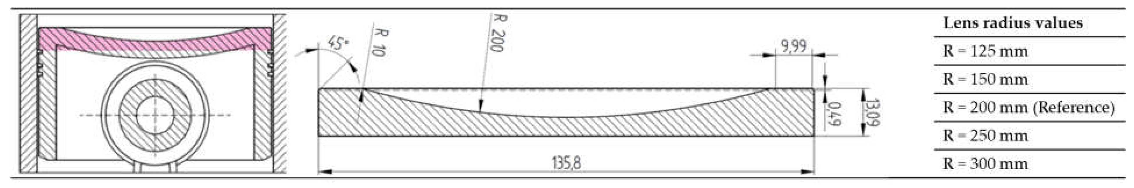
Figure 2.
Comparison of in-cylinder flow structures for different piston bowl geometries. (a) Flow fields along the cylinder’s vertical axis at selected stroke positions (20%, 40%, 60%, 80% of the stroke) relative to the top dead center (TDC), enabling a consistent analysis across geometries; (b) Sectional view through the combustion chamber showing the intake and exhaust channels, the injector, and the resulting air motion generated by the swirl channel, highlighting the interaction between intake dynamics and piston bowl design.
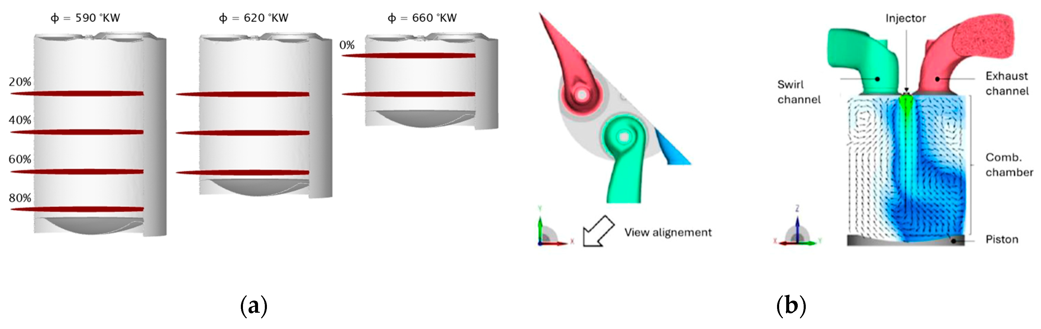
Figure 3.
Comparison between measured and simulated OP with reference piston radius (R = 200 mm). Pressure curse analysis used vor validation purposes of the simulation model
Figure 3.
Comparison between measured and simulated OP with reference piston radius (R = 200 mm). Pressure curse analysis used vor validation purposes of the simulation model
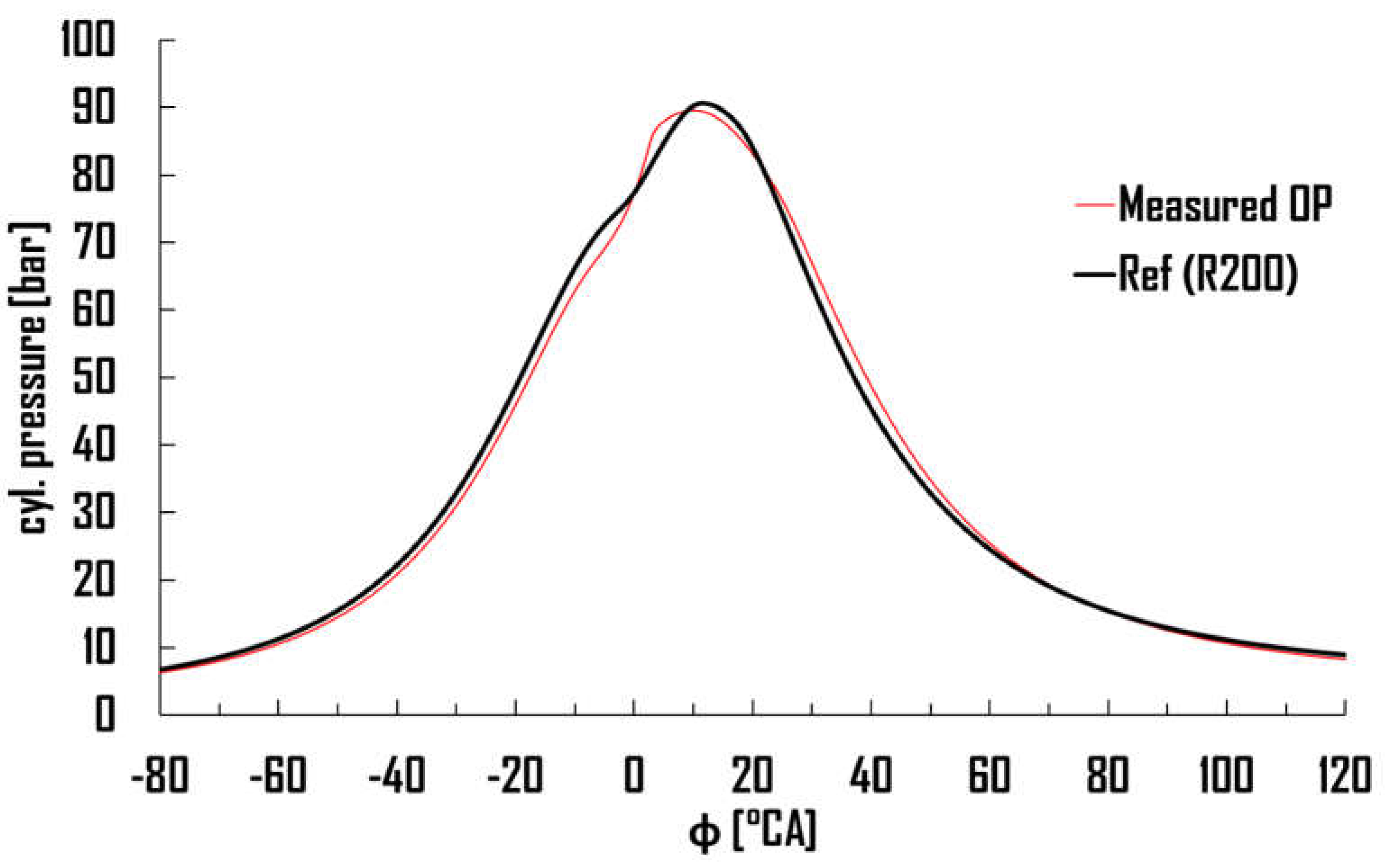
Figure 4.
Comparison of in-cylinder flow velocity fields at selected crank angles and stroke positions based on vertical planes defined in Figure 2a. (a) Piston bowl geometry with lens radius R = 125 mm; (b) Piston bowl geometry with lens radius R = 250 mm. Velocity magnitude is shown using vector fields and a color-coded scale in (m/s).
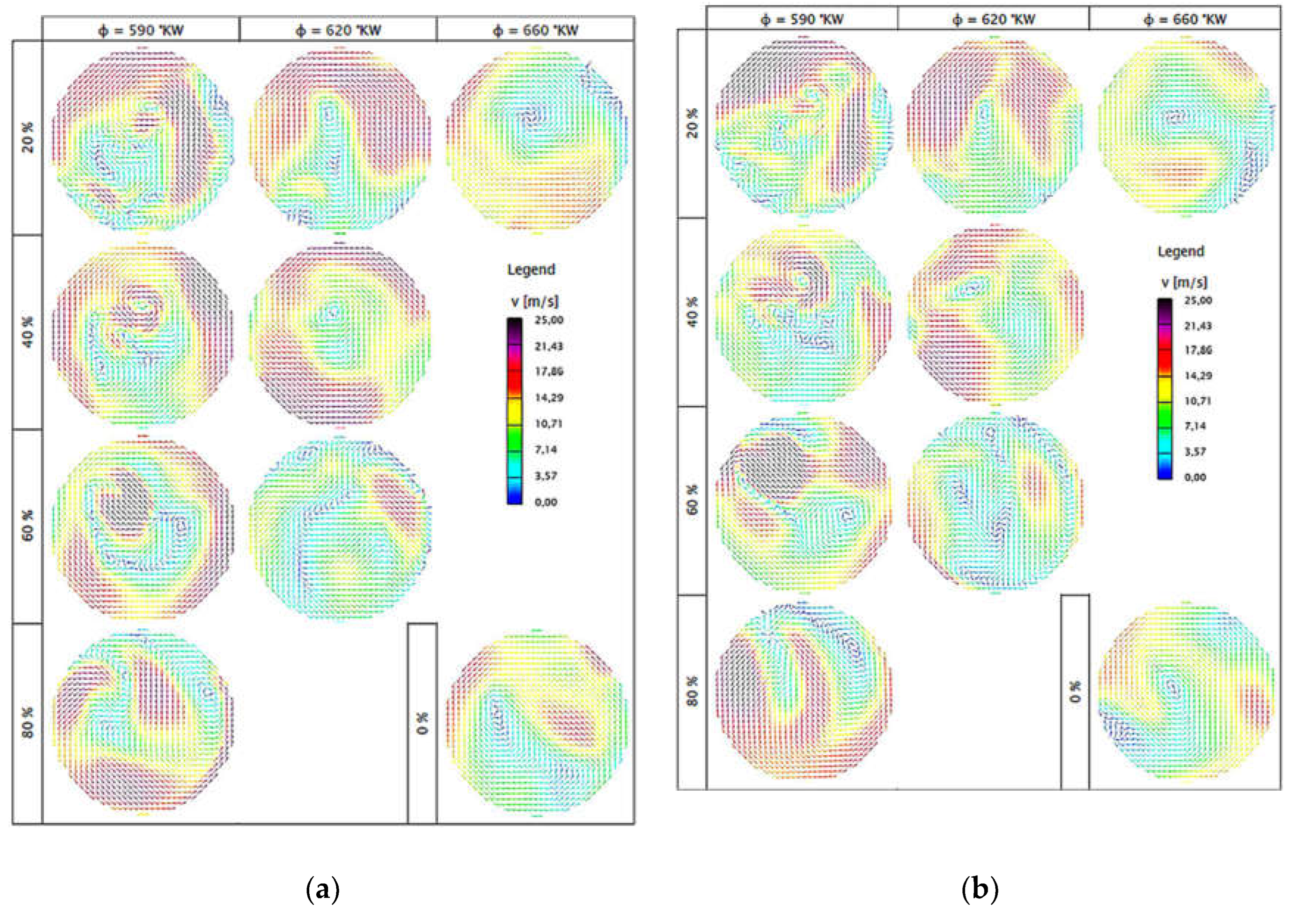
Figure 5.
Hydrogen mass fraction and flow vector fields at crank angles φ = 565°CA and φ = 590°CA for all piston bowl geometries. The sectional view follows the plane defined in Figure 2b. Arrows indicate in-cylinder airflow; color scale represents local hydrogen concentration.
Figure 5.
Hydrogen mass fraction and flow vector fields at crank angles φ = 565°CA and φ = 590°CA for all piston bowl geometries. The sectional view follows the plane defined in Figure 2b. Arrows indicate in-cylinder airflow; color scale represents local hydrogen concentration.
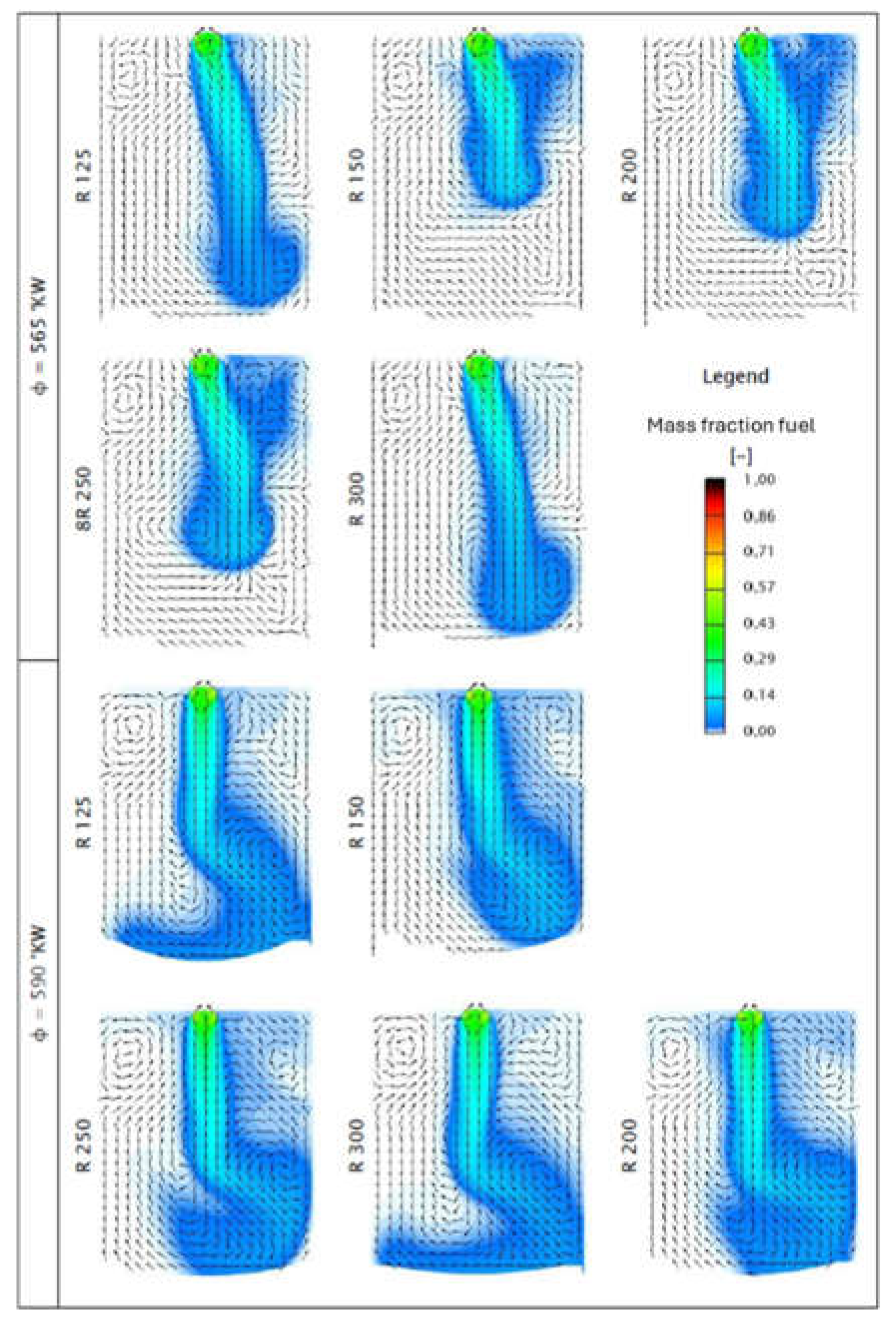
Figure 6.
Comparison of the high-pressure loops at 1500 rpm for hydrogen combustion, highlighting the influence of piston bowl design on peak pressure and compression behavior
Figure 6.
Comparison of the high-pressure loops at 1500 rpm for hydrogen combustion, highlighting the influence of piston bowl design on peak pressure and compression behavior
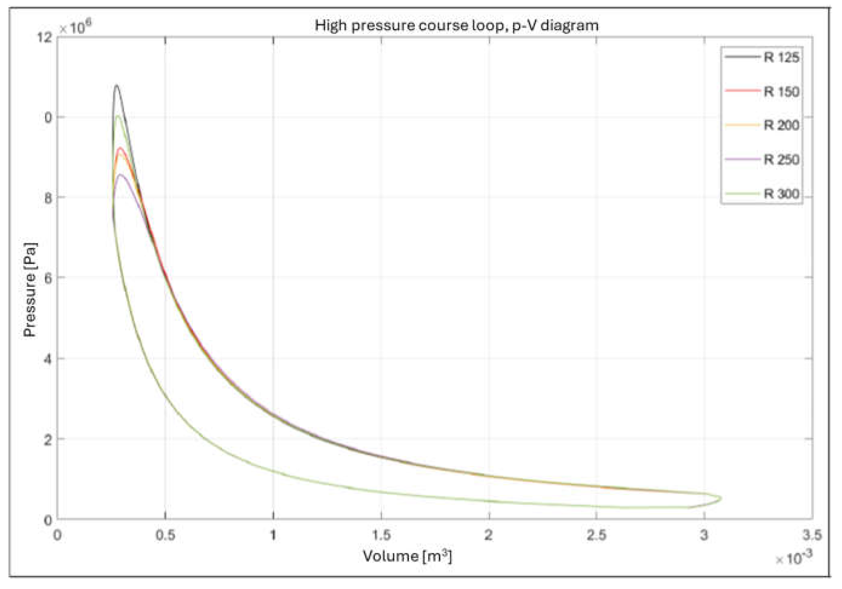
Figure 7.
Visualization of intake valves, exhaust valves, spark plug, and injector positioning, illustrating how charge motion and hydrogen jet development are influenced by geometry
Figure 7.
Visualization of intake valves, exhaust valves, spark plug, and injector positioning, illustrating how charge motion and hydrogen jet development are influenced by geometry
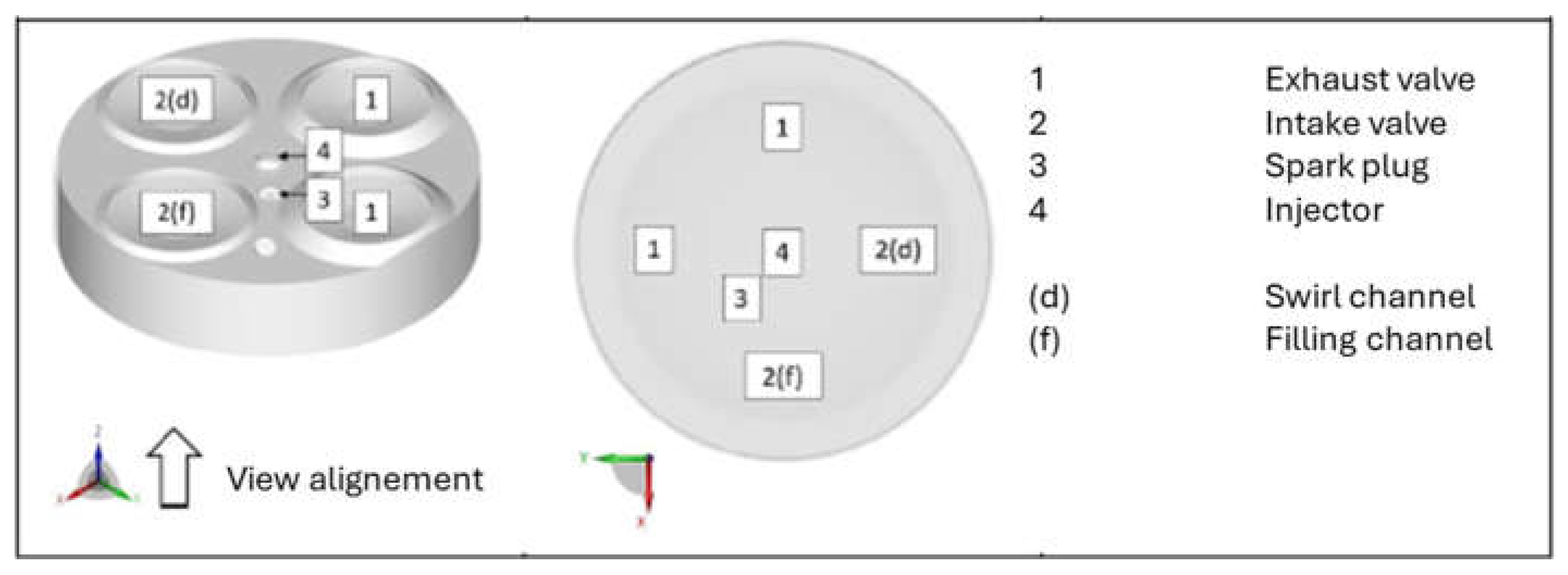
Figure 8.
λ-maps showing local hydrogen concentrations near the spark plug for different piston bowl geometries, emphasizing differences in mixture preparation
Figure 8.
λ-maps showing local hydrogen concentrations near the spark plug for different piston bowl geometries, emphasizing differences in mixture preparation
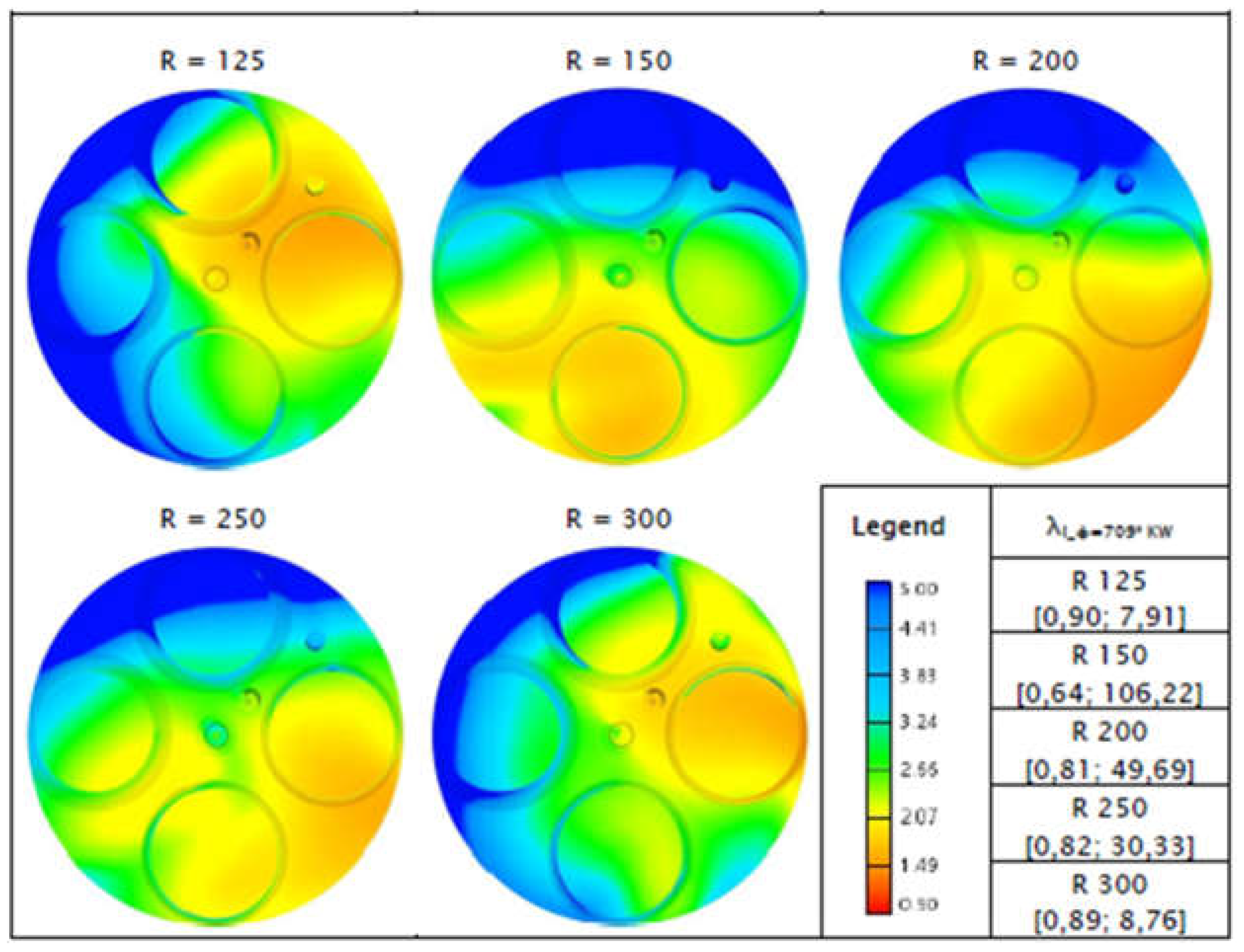
Figure 9.
Detailed comparison of the pressure development during combustion, demonstrating the rate of heat release and efficiency differences resulting from piston bowl variations
Figure 9.
Detailed comparison of the pressure development during combustion, demonstrating the rate of heat release and efficiency differences resulting from piston bowl variations
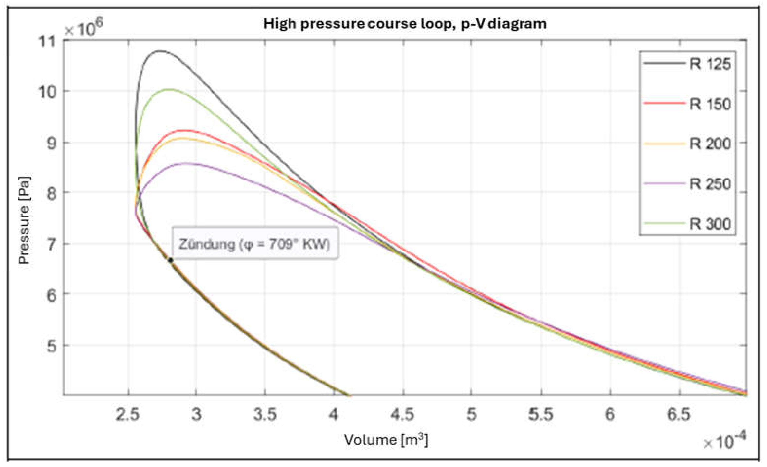
Figure 10.
The left and middle images depict regions of the combustion chamber with equivalence ratios above (λ ≥ 1.01, lean) and below (λ ≤ 1.00, rich or stoichiometric) at φ = 709 °CA, respectively. The right image shows the flame surface density at φ = 730 °CA,
Figure 10.
The left and middle images depict regions of the combustion chamber with equivalence ratios above (λ ≥ 1.01, lean) and below (λ ≤ 1.00, rich or stoichiometric) at φ = 709 °CA, respectively. The right image shows the flame surface density at φ = 730 °CA,
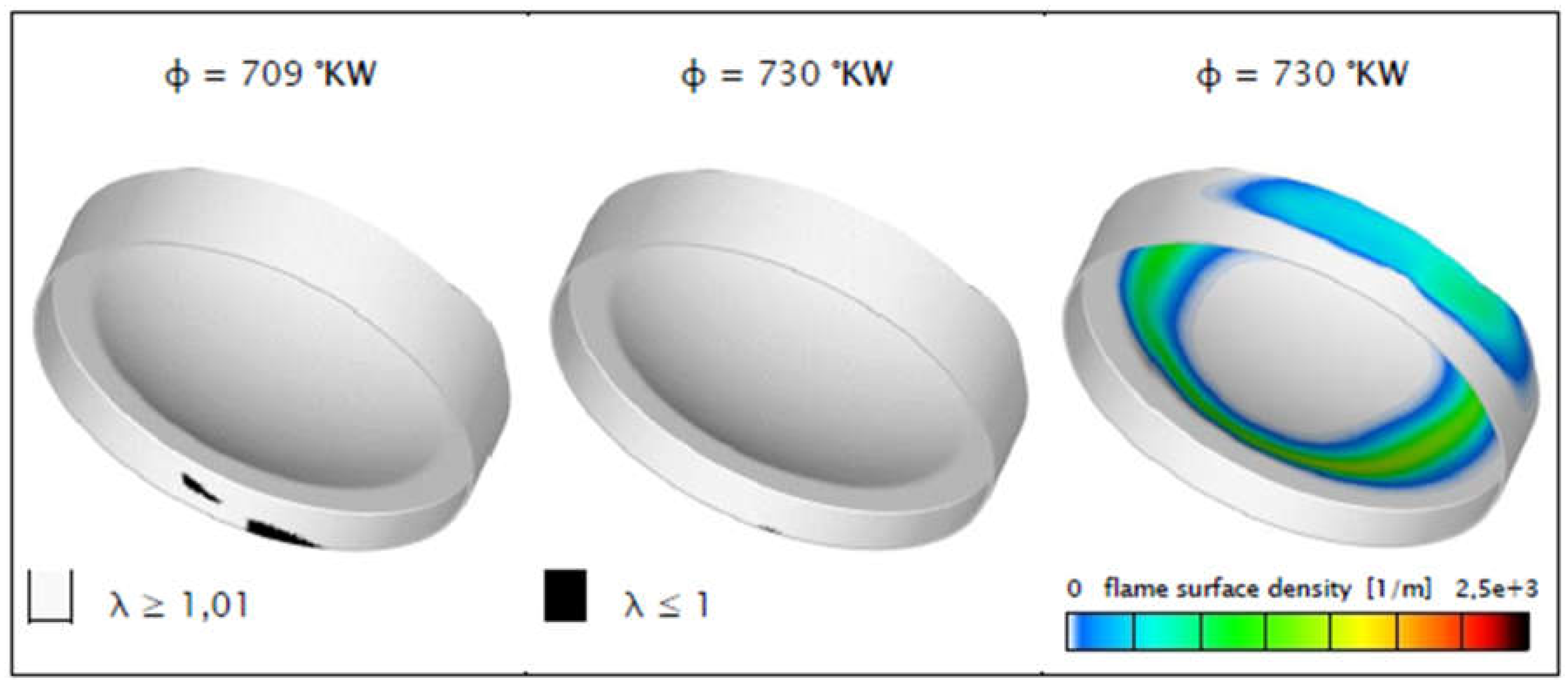
Figure 11.
Simulated NO mass fraction over crank angle φ for five piston bowl geometries. Red line indicates measured NOₓ value for reference.
Figure 11.
Simulated NO mass fraction over crank angle φ for five piston bowl geometries. Red line indicates measured NOₓ value for reference.
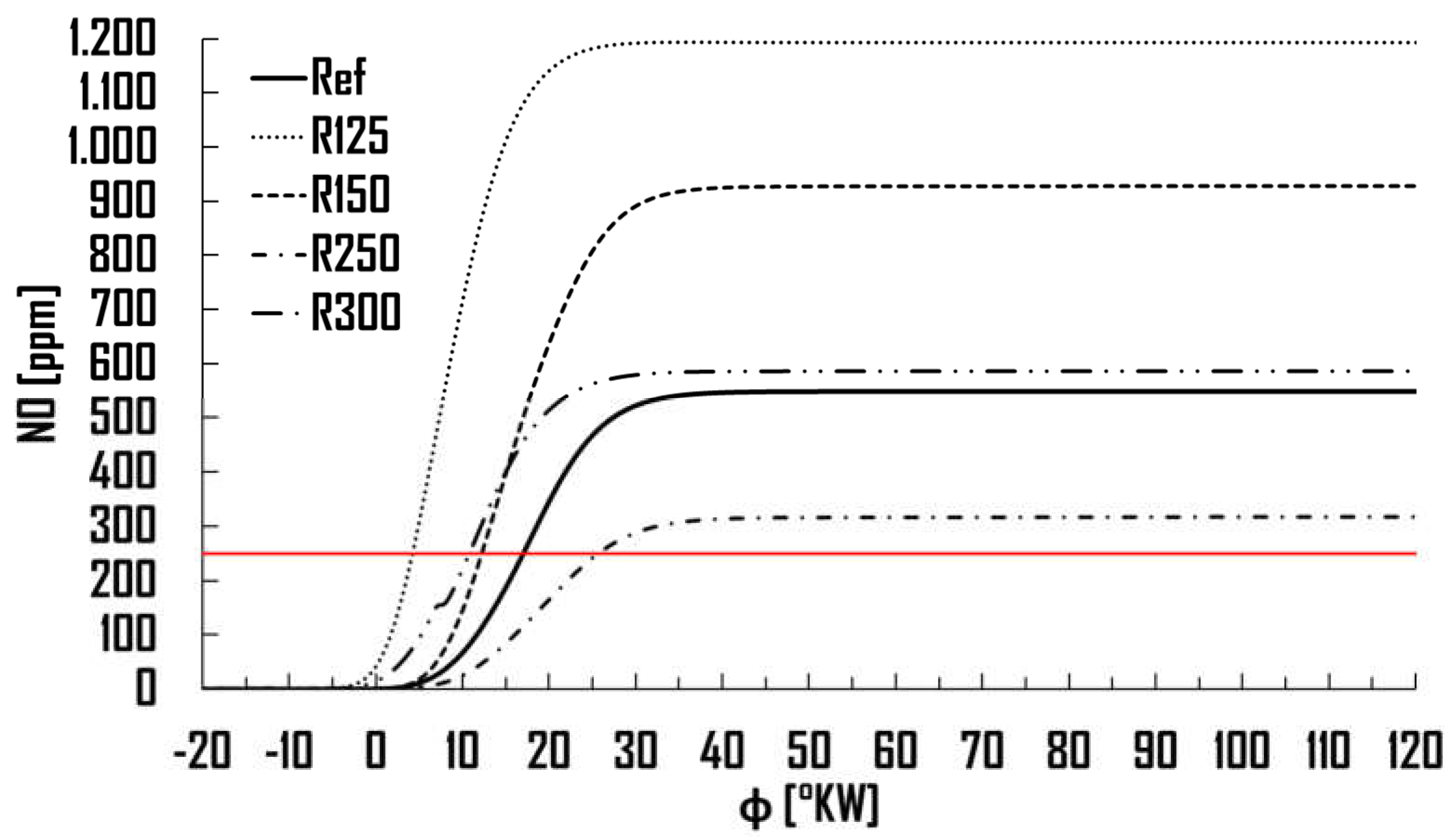
Figure 12.
Average in-cylinder temperature over crank angle for hydrogen combustion. The peak at ≈740 °CA exceeds 1650 K, corresponding to the main NO formation window. Rapid cooling thereafter limits further NO production.
Figure 12.
Average in-cylinder temperature over crank angle for hydrogen combustion. The peak at ≈740 °CA exceeds 1650 K, corresponding to the main NO formation window. Rapid cooling thereafter limits further NO production.
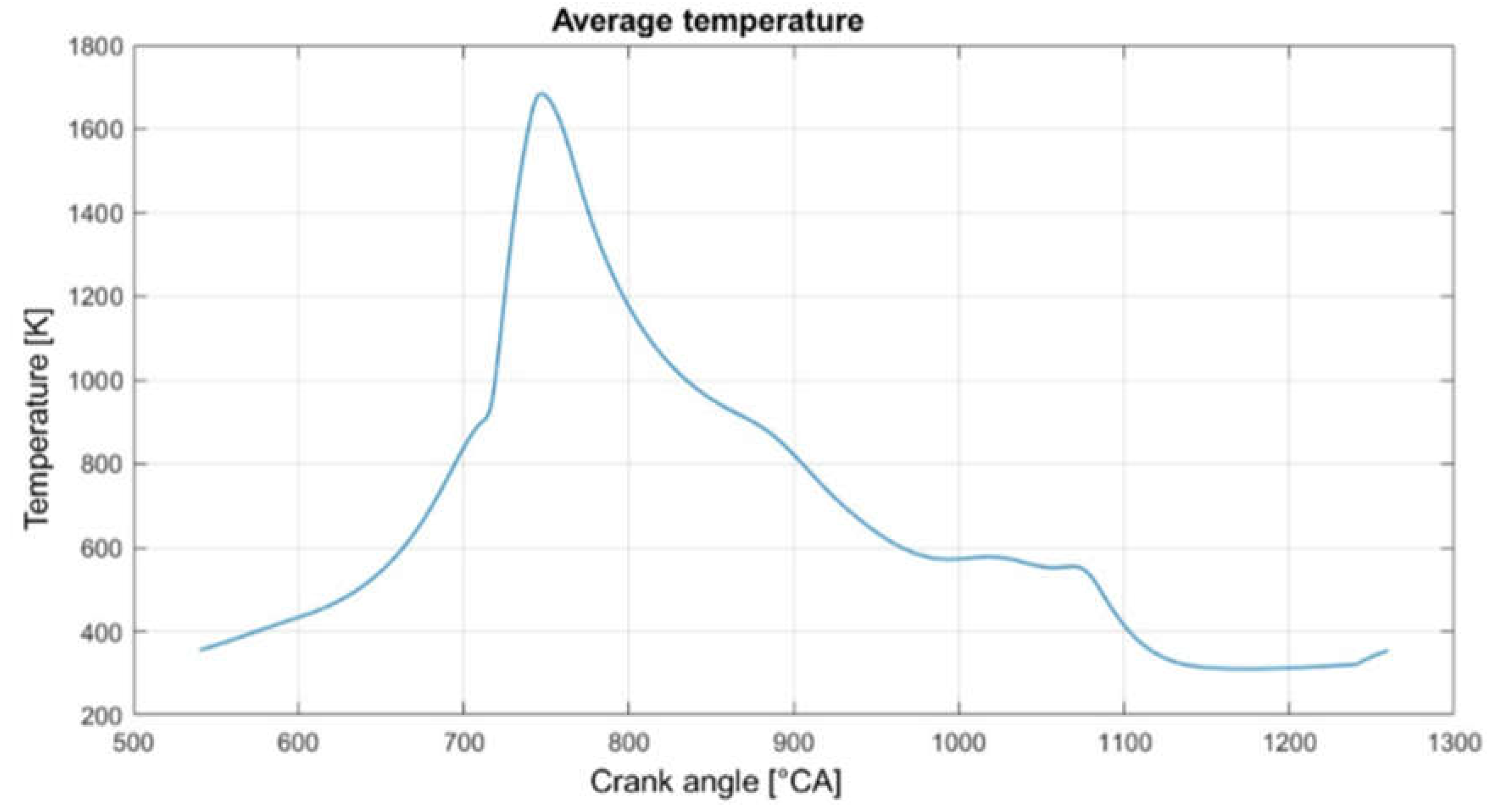
Table 2.
Numerical amounts of gas work in the high-pressure loops
| Piston | Value | |
|---|---|---|
| WH [J] | R 125 | 3267.95 |
| R 150 | 3188.04 | |
| R 200 (ref) | 3163.90 | |
| R 250 | 3161.28 | |
| R 300 | 3223.14 |
Table 3.
Efficiency of the high-pressure loops ηH
| Piston | Value | |
|---|---|---|
| ηH [-] | R 125 | 0.382 |
| R 150 | 0.373 | |
| R 200 (ref) | 0.370 | |
| R 250 | 0.369 | |
| R 300 | 0.377 |
Table 4.
Summary of regions exhibiting air–fuel equivalence ratios significantly above stoichiometry (λ ≥ 1.01) at ignition timing (φ = 709 °CA). Sub-stoichiometric zones are linked to specific geometric features, such as the inlet valve area, fire step, and piston crown edges. A more pronounced occurrence of these regions is associated with wider bowl designs, potentially impacting combustion stability and component durability.
| Piston | |
|---|---|
| R 125 | Low, inlet valve |
| R 150 | - |
| R 200 (ref) | Middle, fire step |
| R 250 | |
| R 300 |
Table 5.
Simulated and measured NO emissions for all piston geometries. PPM values reflect NO at φ = 878 °CA; mass values in mg denote total NO mass within the cylinder.
Table 5.
Simulated and measured NO emissions for all piston geometries. PPM values reflect NO at φ = 878 °CA; mass values in mg denote total NO mass within the cylinder.
| Piston lens R | Measured | 125 | 150 | 200 (ref) | 250 | 300 | |
|---|---|---|---|---|---|---|---|
| NO | [ppm] | 250 | 1194 | 927 | 548 | 327 | 586 |
| [mg] | - | 7.4 | 5.73 | 3.38 | 2.02 | 3.62 | |
Disclaimer/Publisher’s Note: The statements, opinions and data contained in all publications are solely those of the individual author(s) and contributor(s) and not of MDPI and/or the editor(s). MDPI and/or the editor(s) disclaim responsibility for any injury to people or property resulting from any ideas, methods, instructions or products referred to in the content. |
© 2025 by the authors. Licensee MDPI, Basel, Switzerland. This article is an open access article distributed under the terms and conditions of the Creative Commons Attribution (CC BY) license (http://creativecommons.org/licenses/by/4.0/).
Copyright: This open access article is published under a Creative Commons CC BY 4.0 license, which permit the free download, distribution, and reuse, provided that the author and preprint are cited in any reuse.


