
Submitted:
25 April 2025
Posted:
27 April 2025
You are already at the latest version
Abstract
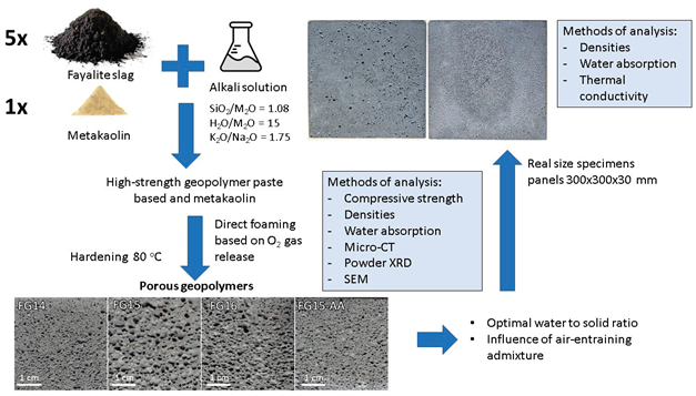
The present work is the first study exploring the potential of geopolymer foams based on fayalite slag, an industrial by-product, as the primary precursor, for lightweight and fireproof construction applications. The research involved synthesis and characterization of geopolymer foams with varying water to solid ratio, followed by testing their physical and mechanical properties. The phase composition and microstructure of the obtained geopolymer foams were examined using powder XRD, Micro-CT and SEM. The geopolymer foams at optimal water to solid ration (0.15) demonstrated 73.2% relative porosity, 0.92 g/cm³ apparent density and 1.3 MPa compressive strength. The use of an air-entraining agent improved compressive strength to 2.8 MPa but lower to 64.5% the relative porosity. Real-size lightweight panel (300 × 300 × 30 mm) specimens were prepared and to measure thermal conductivity coefficient (0.243 W/mK), to evaluate size effect, and the reaction to direct fire. The results of the study of geopolymer foams based on fayalite slag demonstrate their potential as lightweight, insulating and fire-resistant materials suitable for implementation in environmentally friendly construction methods.
Keywords:
geopolymer
; foam
; fayalite
; metakaolin
; lightweight
; fire-resistance
1. Introduction
The Geopolymer foams have attracted significant interest in the construction sector due to their green synthesis protocol and excellent insulation and fire resisting properties [1]. Geopolymers are inorganic polymers synthesized at low temperature (from ambient to about 100 °C) using activation of aluminosilicate precursors [2]. In certain iron rich geopolymer formulations part of Al atoms are substituted by Fe atoms to form ferro-silico-aluminate (Fe-O-Si-O-Al-O-) polymer chain [3]. This suggest possible incorporation of Fe3+ in the tetrahedral network [4]. A particularly promising geopolymer precursor rich in iron is fayalite slag, a by-product of the copper smelting industry [5-8]. Our previous studies showed the potential of fayalite slag as geopolymer precursor [9-11]. The geopolymers prepared by fayalite slag as only precursor was characterized by compressive strength up to 27 MPa [9]. The microstructural examination revealed that only minor amount of the fayalite slag reacted, but certain amount of ferric iron (Fe3+) participate in the structure of newly formed geopolymer gel [9]. The addition of metakaolin to the fayalite slag greatly enhanced the properties of the final geopolymer and the mechanical strength reached 101 MPa compressive strength for geopolymer pastes with standard Vicat consistence [10]. Furthermore, the high strength geopolymer showed thermal resistance up to 1150 °C accompanied by further compressive strength increase to 139 MPa [11]. The obtained geopolymer paste based on fayalite and metakaolin is promising candidate for preparation of foamed material.
Inorganic geopolymer foams are commonly produced by direct chemical foaming method which is based on the generation of gas bubbles within the fresh inorganic matrix [12]. This can be achieved by including foaming agents which induce chemical reactions that release gases such as hydrogen, oxygen, carbon dioxide, ammonium or other [13,14]. The resulted fresh geopolymer foam hardens and the final geopolymer possess a cellular structure that imparts low density and thermal conductivity coefficient, making them suitable for applications such as thermal and sound insulation, fireproofing, and lightweight building components [15]. Geopolymer foams were synthesised by various precursors such as fly and bottom ash [16-18], perlite [19], silica fume [20], metakaolin [21], etc [22,23]. To our knowledge there are no published data on geopolymer foams based on fayalite slag from copper production plants.
The present study focuses on the synthesis of geopolymer foams based on fayalite slag and metakaolin and characterization of their physical, mechanical, and thermal properties and assessment of their suitability for use in construction, such as insulating and fire-resistant materials. We are committed to developing high quality, sustainable fayalite slag-based building materials that can meet the growing needs of the construction industry while minimizing environmental impact.
2. Materials and Methods
The geopolymer precursors in the present study were fayalite slag and metakaolin. The fayalite slag is a fine powdery material – product of flotation of slag from flash furnace and converters at copper production plant. It contains residual moisture, so it was dried in an oven at 80 °C to constant weight. The average particle size of the fayalite slag is about 20 μm, the absolute density was measured – 3.80 g/cm3 [24]. Commercial metakaolin, provided by Kaolin EAD, Bulgaria, was used to improve the properties of the geopolymer. The wet residue of the metakaolin was 0.40 wt. % (for fraction ≤ 45 μm). The measured absolute density of metakaolin was 2.26 g/cm3. The chemical composition of the dried geopolymer precursors is presented at Table 1.
The activator solution was prepared by mixing sodium water glass, potassium hydroxide pellets and tap water to obtain alkaline solution with following molar ratios: SiO2/M2O = 1.08; H2O/M2O = 15 and K2O/Na2O = 1.75, where M2O is the sum of molar quantities of Na2O and K2O. The activator solution was prepared one day before geopolymer synthesis. The air entraining admixture was a commercial product based on anionic surfactants designed for Portland cement mixtures, conforming EN 934-1:2008 (product label GAFB001, provided by Adding Bulgaria Ltd).
The phase composition of the geopolymer foams was studied using powder X-ray diffraction (XRD) analysis on a PANanalytical EMPYREAN Diffractometer system (IMC-BAS), Co anode, 40 V, 30 mA. The SEM and SEM-EDX studies were carried out on a ZEISS SEM EVO 25LS scanning electron microscope with an EDAX Trident system (IMC-BAS) at an accelerating voltage of 25 kV. Secondary electron (SE) and backscattered electron (BSE) signals were used to visualize the microstructure of the geopolymer foams and the phases that compose them. SEM-EDX analysis using an EDAX SDD Apollo 10 EDS detector and Genesis V. 6.2 software was used as an auxiliary method to clarify the phase composition of the studied materials. The study was carried out on polished samples prepared using a special technique that allows better visualization of the porous space and grain phases of geopolymer foam. Sample preparation involved impregnating approximately isometric 1 cm pieces of foams with epoxy resin (EpoFix) under low pressure of about 10-1 bar for 1 hour at room temperature. After hardening, the samples were ground, polished and carbon-coated.
The porous microstructures were examined by X-ray computed tomography (Nikon Metrology, Tring, UK), providing a resolution of 10 µm with a continuous 360 rotation, 180 kV/200 µA. A total of 2880 images were acquired during each scan with an exposure time of 1000 s. Presentation of the tomographic data was carried out using Nikon Metrology’s CT Pro-3D software (Nikon Metrology, Hertfordshire, UK), porosity analysis using VG STUDIO MAX.
The apparent density of the obtained foams was calculated after weighing three dry specimens, cut into a cube with a side of about 4 cm, and accurately measuring its volume using a digital calliper. Absolute density was measured using a gas pycnometer (AccyPy1330, Micromeritic, Norcross, GA, USA) after grinding and sieving samples to sizes less than 25 µm. The relative porosity was calculated based on the ratio between the apparent density and the absolute density.
The relative porosity is presented using two complementary approaches. First, it was calculated based on the ratio between the apparent density and the absolute density of using three specimens, providing an estimate of the total volume fraction of pores within the sample. Second, relative porosity was also evaluated using X-ray computed tomography, which enabled direct visualization and quantification of the internal pore structure, including pore size, shape, distribution, and connectivity.
The water absorption of the samples was determined after weighing three specimens in a dry state and after keeping them in water for 24 hours to constant mass. Compressive strength was measured on three specimens prepared in the form of cut and polished cubes with a side of approximately 45 mm. Specific strength was calculated by compressive strength divided by density of the specimen. The physical and mechanical properties were determined using three samples from each series, with the results reported as mean values accompanied by calculated standard deviations.
The coefficient of thermal conductivity was measured on a FOX 314 Heat Flow Meter in stationary conditions on a dry geopolymer foam specimen with dimension 300 x 300 x 30 mm and polished surfaces.
3. Results
3.1. Geopolymer foam Synthesis
Four types of geopolymer foams were prepared - three with different water to solid ratio (0.14, 0.15, 0.16) with a fixed concentration of the activator solution, respectively FG14, FG15, FG16, and one sample based on FG15 with the addition 0.1 wt.% of a commercial air entraining admixture – sample FG15-AA. The air-entraining admixture aim to improve the pore structure by promoting the formation of uniformly distributed fine air bubbles, reduce pore coalescence and enhances the mechanical stability of the geopolymer foam [25].
The composition design of the prepared samples was product of optimization of the influence of alkali concentration on cellular structure [26]. Preparation of each sample involved mixing fayalite slag and metakaolin in a weight ratio of 5:1 to obtain a homogeneous dry mixture. Then the activator was added and stirred for 90 seconds. After 5 minutes of maturation, an equal amount of oxygen-releasing foaming agent was added to each sample and the resulting mixture was stirred for additional 60 seconds. The amount of gaseous oxygen released was calculated to be 0.14 dm3 (1.5 g 30% H2O2) per 100 g precursor. The obtained mixtures were poured in moulds, covered with polyethylene and placed in a drying oven for 24 hours at 80 ° C. The demoulded samples were left in laboratory conditions for 1 week before studying their physical and mechanical properties.
3.2. Physical and Mechanical Properties
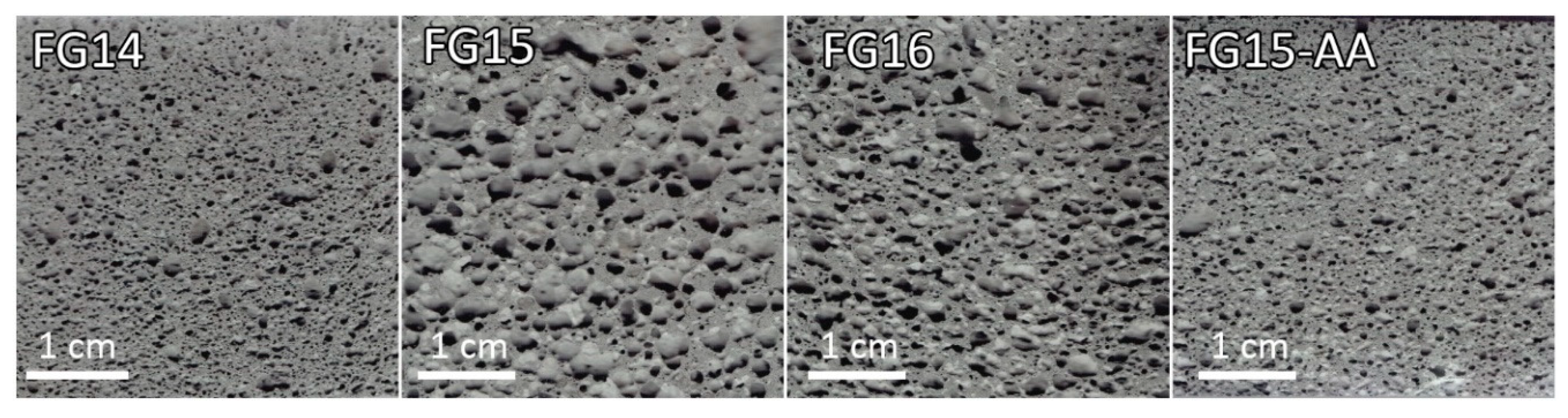
The water to solid ratio significantly influenced the physical properties of the foamed geopolymers due to change in the consistency of the fresh mixtures. It was found that the optimum water to solid ratio was close to 0.15 (sample FG15 series), at which the relative porosity had the highest value (Table 2). A higher water to solid ratio (FG16) lead to a more fluid geopolymer paste, with the porous mixture being more susceptible to pore coalescence, pore collapse and release of entrapped bubbles, resulting in lower relative porosity and higher density. On the other hand, a lower water to solids ratio (FG14) resulted in a stiffer geopolymer paste, which reduced its elasticity and led to a decrease in relative porosity and an increase in density. The notably high densities observed in the geopolymer foams based on fayalite slag can be attributed to the high iron content in the raw material. As a result, the produced foams exhibited relatively higher densities ranging from approximately 0.92 to 1.25 g/cm3 compared to other studies. Ducman and Korat obtained fly-ash based foams with density about 0.60 g/cm3 using similar amount of H2O2 [27]. Sample FG15 showed the highest water absorption – 30.9%. The compressive strength of the samples varied in the range of 1.3 – 2.8 MPa and was negatively correlated with the relative porosity. The effect of the air-entraining additive (FG15-AA) is manifested in a decrease in pore coalescence and a comparatively more uniform porosity (Figure 1). Sample FG15-AA was characterized by increased density, compressive strength and specific strength, as well as reduced relative porosity and water absorption.

Table 2.
Influence of water to solid ratio to physical and mechanical properties of the foamed fayalite based geopolymer).
Table 2.
Influence of water to solid ratio to physical and mechanical properties of the foamed fayalite based geopolymer).
| Series | Water to solid ratio | Density, g/cm3 | Absolute density, g/cm3 | Relative porosity, % | Water absorption, % | Compressive strength, MPa |
Specific strength, kN/m.kg |
|---|---|---|---|---|---|---|---|
| FG14 | 0.14 | 1.25 | 3.44 | 63.7 | 19.3 ± 0.6 | 2.4 ± 0.2 | 1.96 |
| FG15 | 0.15 | 0.92 | 3.43 | 73.2 | 30.9 ± 0.3 | 1.3 ± 0.1 | 1.46 |
| FG16 | 0.16 | 1.08 | 3.42 | 68.4 | 23.8 ± 1.1 | 1.5 ± 0.1 | 1.39 |
| FG15-AA | 0.15 | 1.22 | 3.44 | 64.5 | 20.4 ± 0.2 | 2.8 ± 0.1 | 2.3 |
Figure 1.
Porous structure of fayalite based geopolymer foams visualized by images captured on a 2D scanner when scanning cut and polished surfaces of the foam samples.
Figure 1.
Porous structure of fayalite based geopolymer foams visualized by images captured on a 2D scanner when scanning cut and polished surfaces of the foam samples.
3.3. X-Ray Computed Tomography (Micro-CT)
X-ray computed Tomography was used as a non-destructive method for 3-D visualization and analysis of the pore space of geopolymer foams. Regions of interest (ROIs) with approximate dimensions of 30x30 mm were selected to standardize the analysis across samples, following the automatic surface determination. Minimal volumetric discrepancies between ROIs were noted, which are likely due to variations in voxel distributions. The results summarized in Table 3 show a discrepancy with the relative porosity data obtained by gas pycnometry (Table 2). A possible explanation for this is that the resolution of the Micro-CT used does not provide satisfactory information for pores smaller than 10 μm [28], which leads to apparently lower relative porosity values obtained by Micro-CT. At the same time, all trends established by the two methods are in good agreement.
Мaterials FG16 and FG15 demonstrate the highest relative porosity levels, at 50.84% and 54.21%, respectively, with pore counts of 33,726 and 23,549 (Table 3). The correlation between porosity percentage and pore count suggests that FG15 exhibits larger pore structures, consistent with macroscopic observations. In both FG15 and FG16, a significant interconnected pore conglomerate was identified, with volumes of 14,107 mm³ and 13,395 mm³, respectively. The remaining pore volume, 523 mm³ in FG15 and 394 mm³ in FG16, consisted predominantly of isolated pores. Material FG14 exhibited a reduction in both relative porosity (38.58%) and pore count (20,575) compared to FG15 and FG16. A major connected pore cluster was identified with a volume of 10,081 mm³, while the remaining 324 mm³ volume consisted of smaller, discrete pores. These observations are consistent with macroscopic findings. In contrast, the surfactant-modified material FG15-AA demonstrated the highest pore count (43,293) yet the lowest relative porosity (33.50%). This material contained a large connected pore network, with a volume of 5,956 mm³, and an additional 2,701 mm³ volume comprising smaller, closed pores. A notable aspect of FG15-AA is the presence of approximately 490 pores exceeding 0.9 mm³ in volume, compared to 90 in FG15, 33 in FG16, and only 3 in FG14. This distribution indicates substantial differences in pore size characteristics across the materials. This detailed analysis highlights distinct differences in the porosity of the materials studied, suggesting that pore size, their connectivity and distribution are material dependent and have a significant impact on the bulk properties of each sample.
Figure 2.
Porous structure of fayalite based geopolymer foams visualized by images captured on a 2D scanner when scanning cut and polished surfaces of the foam samples.
Figure 2.
Porous structure of fayalite based geopolymer foams visualized by images captured on a 2D scanner when scanning cut and polished surfaces of the foam samples.
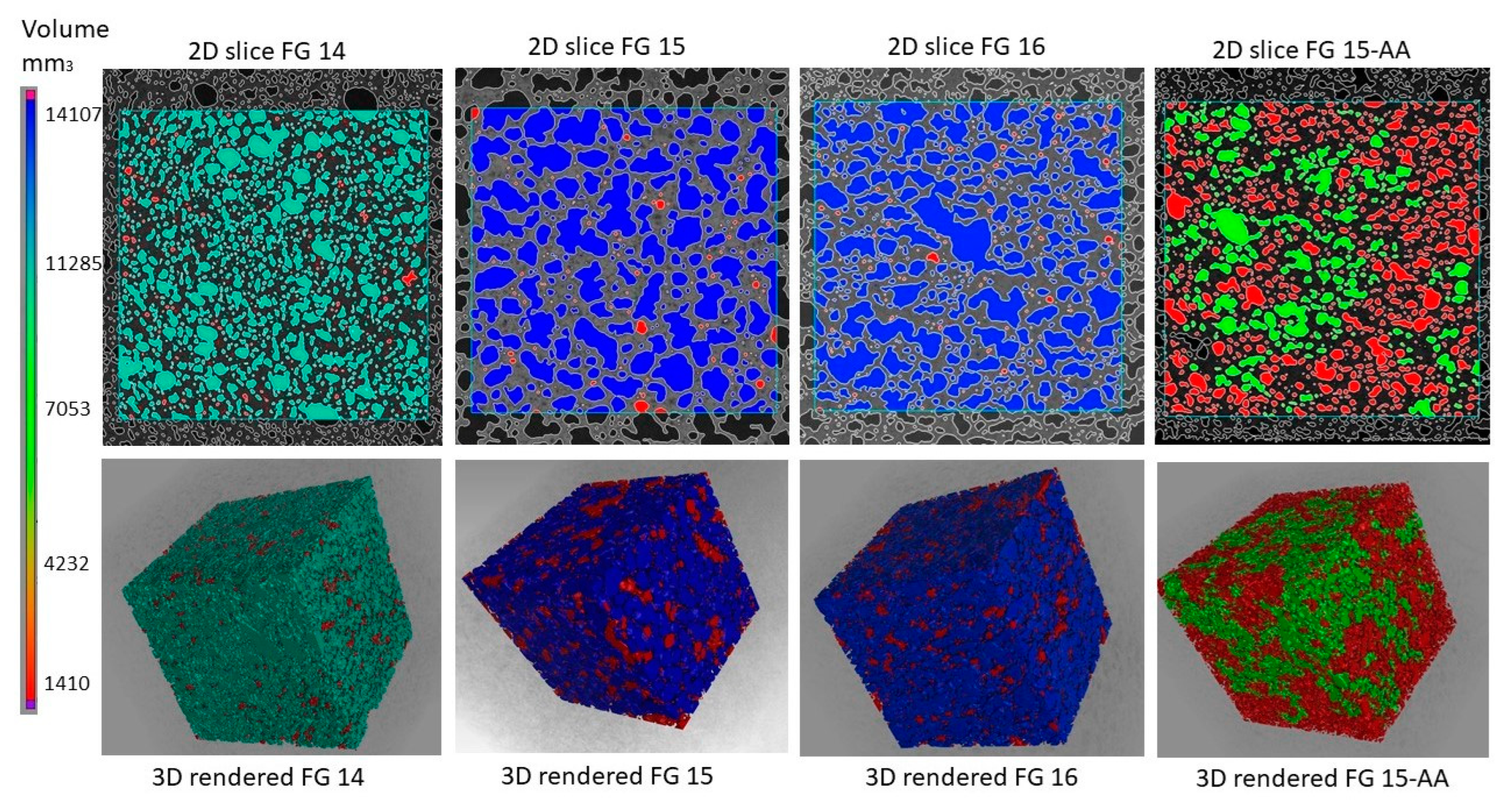
Table 3.
Summary of Porosity Analysis Data.
| Series | FG14 | FG15 | FG16 | FG15-AA |
|---|---|---|---|---|
| Pore count | 20575 | 23549 | 33726 | 43293 |
| Relative porosity, % | 38.58 | 54.21 | 50.84 | 33.50 |
| Total volume pores, mm3 | 10405 | 14630 | 13789 | 8657 |
3.4. Powder XRD
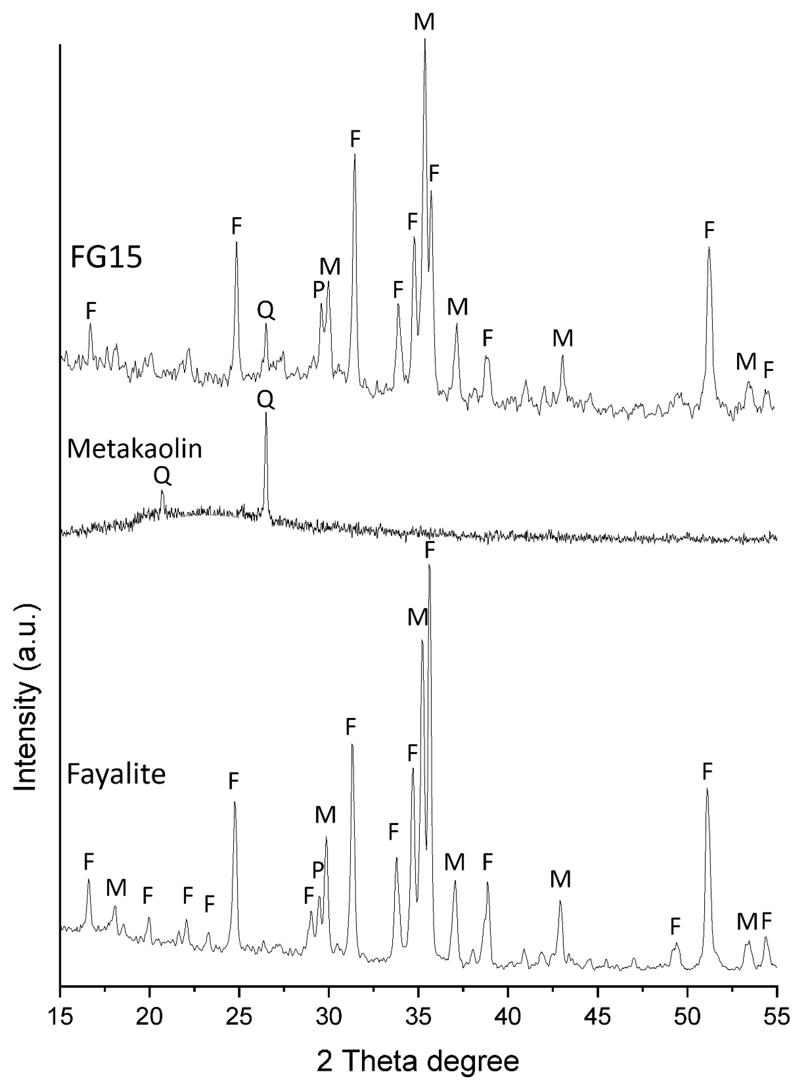
The XRD patterns of all the synthesized fayalite-based foamed geopolymers were similar; therefore, Figure 3 presents a representative pattern from series FG15, along with the patterns of the raw fayalite slag and metakaolin for comparison. The main phases fayalite, magnetite and pyroxene presented in the fayalite slag remained predominantly inert after geopolymerization. It was observed minor differences in certain relative intensities of fayalite, which could be due to partial reaction of fayalite particles. Тhe fayalite slag contained about 10% Fe in amorphous phase (detected previously by Mossbauer spectroscopy[9]). On other hand metakaolin showed amorphous structure with broad hump between 15-302θ° with inclusion of sharp quartz peaks. The amorphous phases in the slag and metakaolin react to form a geopolymer gel, which corresponds to a minor amorphous hump between 25–40 2θ°. The quartz inclusions in the metakaolin remain inert after geopolymerization.
In the geopolymer foams synthesized from fayalite slag, the mineral phases fayalite and magnetite primarily act as inert fillers within the matrix. These phases are characterized by their relatively high absolute densities—approximately 4.39 g/cm³ for fayalite and 5.17 g/cm³ for magnetite—which contribute significantly to the overall density of the resulting foam. The presence of heavy mineral phases increased the bulk density of the foam and could also impact its structural stability. Specifically, the presence of high-density particles can affect the balance of internal forces within the foamed structure, potentially leading to foam collapse or instability under the influence of gravity during the curing process.
Figure 3.
Powder XRD patterns of fayalite slag, metakaolin and sample FG15. Legend: F - fayalite, M - magnetite, P - pyroxene, Q - quartz.
Figure 3.
Powder XRD patterns of fayalite slag, metakaolin and sample FG15. Legend: F - fayalite, M - magnetite, P - pyroxene, Q - quartz.
3.5. SEM
The SEM examination revealed some similarities and differences in the samples that are consistent with or enhance the results obtained by other methods. Impregnation of foam samples with epoxy resin proved to be an effective method for identifying interconnected and isolated pores in the studied materials (Figure 4). The studied samples differ from each other in the size of the pores, their distribution and filling with epoxy resin. Two pairs of samples FG15-AA and FG14 (Figure 4a, d) and FG15 and FG16 (Figure 4e, f) have relatively close microstructural properties within the pairs which corresponds well to the physical and mechanical properties of the materials in Table 2. The first pair of samples (FG15-AA and FG14) is characterized by the predominance of pore systems with sizes of 50-150 µm and 300-500 µm. The main difference within the first group of samples is the degree of filling of pores 300–500 µm with epoxy resin – unlike sample FG15-AA, in sample FG14 all pores are filled (interconnected). Small pores of 50–150 µm in size in two samples are almost all isolated, since they are not filled with epoxy resin. The second pair of samples FG15 and FG16 (Figure 4e, f) is distinguished by the presence of a system of very large pores > 1 mm. Other predominant pore systems in the samples are 50-200 µm and 300-600 µm. Pores >1 cm and 300-600 µm are partially or completely filled with epoxy resin (interconnected pores). Some of the 50-200 µm pores in sample FG15 are also interconnected because they are filled with epoxy resin.
The study of BSE images coupled with EDX analysis of massive parts of foams on example of sample FG15-AA (Figure 4c) made it possible to establish all the phases identified by XRD analysis (Figure 3): fayalite, magnetite, pyroxene, quartz. In addition to these phases, aluminosilicate glass containing Na, K, Ca, Fe and Cl, relics of metakaolin material were also found. The glass found is a possible amorphous candidate for an iron carrier described in [9].
3.6. Real-Size Experiments - Thermal Conductivity and Fire Resistance Test
A real-size experiment was performed adopting sample FG15-AA, utilizing 5 kg fayalite slag. This composition was chosen because it demonstrated the optimal balance of physical and mechanical properties, making it the most suitable candidate for application-oriented evaluation. The mixture was homogenized using conventional mortar mixer Rubimix 7 (1200W, 760 rpm). The same mixing procedure was followed and the fresh mixture was poured in plastic moulds to prepare geopolymer foamed blocks with dimensions 300 × 300 × 30 mm. After finishing the curing procedure, the specimens were polished to ensure even surfaces (Figure 5). Certain pore agglomeration was visible at the polished top surface. The density and water absorption were determined to 1.29 g/cm3 and 15.35%, respectively (Table 4). It was observed slightly higher values of density and water absorption compared to initial sample FG15-AA due to size effect.
The geopolymer foamed blocks were evaluated by measuring the thermal conductivity coefficient (λ). Despite of the relatively high density (1.29 g/cm3), the geopolymer foam based on fayalite showed very low thermal conductivity coefficient - 0.243 W/mK. Results of other studies of foamed geopolymers at similar density obtained on laboratory scale specimens: slightly higher λ = 0.27 W/mK, at even lower density - 1.20 g/cm3 was obtained by E. Yatsenko et al. on geopolymer foams based on recycled ash and slag [29], while Pralat et al. prepared specimens with λ = 0,29 W/mK at about 1.00 g/cm3 density, for geopolymer based on metakaolin modified with gypsum [30].
Table 4.
Properties of produced real-size geopolymer foam specimens.
| Sample | Density | Water absorption | Thermal conductivity coefficient |
|---|---|---|---|
| Real-size specimen based on FG15-AA (300 x 300 x 30 mm) |
1.29 g/cm3 | 15.35% | 0.243 W/mK |
A preliminary fire-resistance test was performed with propane-butane jet-torch on specimen with dimension 150 × 150 × 30 mm (Figure 6-left). The measured temperature at the reverse-side of the specimen reached 225 °C after 15 minutes. The specimen remained its integrity, exhibiting minor surface cracking (Figure 6-right). Change in color to reddish was observed suggesting hematite formation. This result align with our previous furnace experiments [11] on non-foamed geopolymers based on fayalite slag which demonstrated thermal resistance up to 1150 °C. In those tests, fayalite and magnetite transformed into hematite above 800 °C in the outer layers—a phenomenon also observed in the current direct fire experiments. In the foamed structure, the open porosity likely facilitates deeper oxygen penetration, promoting hematite formation in higher depth. This phase transformation increases the rigidity of the outer layer and raises the melting point of the material [11], supporting the potential of fayalite-based geopolymer foams as fire-resistant materials.
4. Conclusions
The present study demonstrates the feasibility of synthesizing geopolymer foams using high strength geopolymer paste based on fayalite slag and metakaolin. The findings highlight the potential of fayalite slag, a by-product of the copper smelting industry, to serve as a sustainable raw material in the development of advanced building materials. Key observations and conclusions are as follows:
- Fayalite slag, despite its high density (3.80g/cm3), can be effectively utilized to produce lightweight geopolymer materials through the direct foaming method;
- Geopolymer foams with a water-to-solid ratio of 0.15 (series FG15) demonstrated optimal characteristics, achieving the highest relative porosity (73.2%) and the lowest measured density (0.92 g/cm3). The absolute density was measured to 3.43 g/cm3, which is comparatively high for geopolymers due to the presence of dense mineral phases in the fayalite slag, such as fayalite and magnetite. As a result, the foams combine the lightweight nature of porous materials with a geopolymer gel matrix composed of inherently heavier components;
- The addition of air-entraining agents resulted in geopolymer foam with more pore counts, uniform pore distribution, decreased pore size, reduced coalescence, and improved mechanical properties. This modification increased compressive strength to 2.8 MPa, with a decrease in relative porosity (64.5%);
- Microcomputed tomography revealed that pore network consisted of interconnected pores. The pore structure was greatly influenced by water to solid ratio. The FG15 series exhibited the highest relative porosity and interconnected pore networks, whereas FG15-AA demonstrated a higher pore count with smaller, more evenly distributed pores;
- Powder XRD analysis and SEM study indicated that main phases in fayalite slag – fayalite and magnetite remained inert during geopolymerization, with partial reactivity observed in the amorphous phases. The metakaolin and probably ferro-aluminosilcate glass in the fayalite slag contributed to the formation of geopolymer gel, evidenced by the amorphous hump in the XRD pattern, while the crystalline phases such as quartz, fayalite, magnetite and pyroxene remained unreacted acting as a filler in the geopolymer matrix.;
- Real-size specimens (300 x 300 x 30 mm) prepared using recipe FG15-AA showed slightly higher values of density (1.29 g/cm3) but lower water absorption (15.35%) compared to initial sample FG15-AA (1.22 g/cm3, 20.4%, respectively) due to size effect and scaling the technology of preparation. The geopolymer foam blocks was characterized by thermal conductivity coefficient of 0.243 W/mK. The geopolymer foam resisted direct flame exposure without disintegration, highlighting its potential as a fire-resistant material.
Geopolymer foams synthesized from fayalite slag exhibit excellent properties combining thermal insulation, fireproofing, and lightweight properties. The utilization of fayalite slag supports sustainable construction practices by reducing the environmental footprint of conventional building materials.
In conclusion, fayalite slag-based geopolymer foams represent a promising class of eco-friendly and high-performance materials. Further studies are warranted to optimize their synthesis process, evaluate long-term durability, and expand their applications in the construction industry. This work highlights the potential of industrial by-products to be transformed into valuable resources for sustainable development.
Author Contributions
For research articles with several authors, a short paragraph specifying their individual contributions must be provided. The following statements should be used “Conceptualization, AN; methodology, A.N., M.T., I.R., M.R. and I.G.; software, A.N., M.T., I.R., M.R. and I.G..; validation, A.N., M.T., I.R., M.R. and I.G.; formal analysis, A.N., M.T., I.R., M.R. and I.G.; investigation, A.N., M.T., I.R., M.R. and I.G.; resources, A.N., M.T., I.R., M.R. and I.G.; data curation, A.N., M.T., I.R., M.R.,I.G. and K.K.; writing—original draft preparation, A.N., M.T., I.R., M.R. and I.G.; writing—review and editing, A.N., M.T., I.R., M.R.,I.G. and K.K.; visualization, A.N., M.T., I.R., M.R.,I.G. and K.K.; supervision, A.N.; project administration, A.N. and M.T.; funding acquisition, A.N. and M.T. All authors have read and agreed to the published version of the manuscript.” Please turn to the CRediT taxonomy for the term explanation. Authorship must be limited to those who have contributed substantially to the work reported.
Funding
This research was funded by No. KП-06-H77/9 from 4.12.2023.”.
Institutional Review Board Statement
Not applicable
Informed Consent Statement
Not applicable
Data Availability Statement
The data presented in this study are available on request from the corresponding author. The data are not publicly available.
Acknowledgments
The authors have reviewed and edited the output and take full responsibility for the content of this publication.”
Conflicts of Interest
The authors declare no conflict of interest
Abbreviations
The following abbreviations are used in this manuscript:
| Micro-CT | X-ray computed tomography |
| ROI | Region of interest |
| SEM | Scanning electron microscopy |
| XRD | X-ray diffraction |
References
- Korniejenko, K.; Pławecka, K.; Bazan, P.; Figiela, B.; Kozub, B.; Mróz, K.; Łach, M. Green building materials for circular economy—geopolymer foams. Proc. Eng. Technol. Innov 2023, 25, 26–34. [Google Scholar] [CrossRef]
- Davidovits, J. Geopolymers: Ceramic-like inorganic polymers. J. Ceram. Sci. Technol 2017, 8, 335–350. [Google Scholar] [CrossRef]
- Davidovits, J.; Davidovits, R. Ferro-Sialate Geopolymers (-Fe-O-Si-O-Al-O-). Geopolymer Institute Library 2020.
- Lemougna, P.N.; MacKenzie, K.J.; Jameson, G.N.; Rahier, H.; Chinje Melo, U. The role of iron in the formation of inorganic polymers (geopolymers) from volcanic ash: a 57 Fe Mössbauer spectroscopy study. Journal of Materials Science 2013, 48, 5280–5286. [Google Scholar] [CrossRef]
- Onisei, S.; Lesage, K.; Blanpain, B.; Pontikes, Y. Early age microstructural transformations of an inorganic polymer made of fayalite slag. Journal of the American Ceramic Society 2015, 98, 2269–2277. [Google Scholar] [CrossRef]
- Komnitsas, K.; Zaharaki, D.; Perdikatsis, V. Geopolymerisation of low calcium ferronickel slags. Journal of Materials Science 2007, 42, 3073–3082. [Google Scholar] [CrossRef]
- Adediran, A. Alkali activation of fayalite slag. A. Adediran, 2017.
- Mihailova, I.; Uzunov, I.; Mehandjiev, D. Waste Copper Slag/Aluminium Dross-Based Geopolymer. Journal of Chemical Technology and Metallurgy 2021, 56, 653–659. [Google Scholar]
- Nikolov, A. Alkali-activated geopolymers based on iron-rich slag from copper industry. In Proceedings of the IOP Conference Series: Materials Science and Engineering; 2020; p. 012006. [Google Scholar] [CrossRef]
- Nikolov, A. Characterization of geopolymer based on fayalite waste and metakaolin with standard consistence. Comptes rendus de l’Académie bulgare des Sciences, 2021; 74. [Google Scholar] [CrossRef]
- Nikolov, A.; Karamanov, A. Thermal properties of geopolymer based on fayalite waste from copper production and metakaolin. Materials 2022, 15, 2666. [Google Scholar] [CrossRef]
- Kočí, V.; Černý, R. Directly foamed geopolymers: A review of recent studies. Cement and Concrete Composites 2022, 130, 104530. [Google Scholar] [CrossRef]
- Hajimohammadi, A.; Ngo, T.; Mendis, P.; Sanjayan, J. Regulating the chemical foaming reaction to control the porosity of geopolymer foams. Materials & Design 2017, 120, 255–265 . [Google Scholar] [CrossRef]
- Xu, F.; Gu, G.; Zhang, W.; Wang, H.; Huang, X.; Zhu, J. Pore structure analysis and properties evaluations of fly ash-based geopolymer foams by chemical foaming method. Ceramics International 2018, 44, 19989–19997 . [Google Scholar] [CrossRef]
- Zhang, Z.; Provis, J.L.; Reid, A.; Wang, H. Geopolymer foam concrete: An emerging material for sustainable construction. Construction and Building Materials 2014, 56, 113–127. [Google Scholar] [CrossRef]
- Nikolov, A.; Barbov, B. Lightweight geopolymer based on fly ash. Review of the Bulgarian Geological Society 2018, 79, 23–24. [Google Scholar]
- František, Š.; Rostislav, Š.; Zdeněk, T.; Petr, S.; Vít, Š.; Zuzana, Z.C. Preparation and properties of fly ashbased geopolymer foams. Ceramics-Silikáty 2014, 58, 188–197. [Google Scholar]
- Suksiripattanapong, C.; Krosoongnern, K.; Thumrongvut, J.; Sukontasukkul, P.; Horpibulsuk, S.; Chindaprasirt, P. Properties of cellular lightweight high calcium bottom ash-portland cement geopolymer mortar. Case Studies in Construction Materials 2020, 12, e00337. [Google Scholar] [CrossRef]
- Vaou, V.; Panias, D. Thermal insulating foamy geopolymers from perlite. Minerals Engineering 2010, 23, 1146–1151. [Google Scholar] [CrossRef]
- Shakouri, S.; Bayer, Ö.; Erdoğan, S.T. Development of silica fume-based geopolymer foams. Construction and Building Materials 2020, 260, 120442. [Google Scholar] [CrossRef]
- Bai, C.; Zheng, K.; Sun, F.; Wang, X.; Zhang, L.; Zheng, T.; Colombo, P.; Wang, B. A review on metakaolin-based porous geopolymers. Applied Clay Science 2024, 258, 107490. [Google Scholar] [CrossRef]
- Novais, R.M.; Pullar, R.C.; Labrincha, J.A. Geopolymer foams: An overview of recent advancements. Progress in Materials Science 2020, 109, 100621. [Google Scholar] [CrossRef]
- Shen, S.; Tian, J.; Zhu, Y.; Zhang, X.; Hu, P. Synthesis of industrial solid wastes based geopolymer foams for building energy conservation: Effects of metallic aluminium and reclaimed materials. Construction and Building Materials 2022, 328, 127083. [Google Scholar] [CrossRef]
- Manolova, E. Aurubis iron-silicate fines: universal sustainable construction material: a state-of-the-art review. In Proceedings of the IOP Conference Series: Materials Science and Engineering; 2020; p. 012005. [Google Scholar] [CrossRef]
- Pham, L.T.; Cramer, S.M. Effects of air-entraining admixtures on stability of air bubbles in concrete. Journal of Materials in Civil Engineering 2021, 33, 04021018. [Google Scholar] [CrossRef]
- Nikolov A, T. , L, Barbov B. Lightweight heavy geopolymer foam based on fayalite slag: influence of alkali concentration on cellular structure. Machines, Technologies, Materials, 2025. [Google Scholar]
- Ducman, V.; Korat, L. Characterization of geopolymer fly-ash based foams obtained with the addition of Al powder or H2O2 as foaming agents. Materials characterization 2016, 113, 207–213. [Google Scholar] [CrossRef]
- Karamanov, A.; Colombini, E.; Ferrante, D.; Georgiev, I.; Raykovska, M.; Karamanova, E.; Atanasova, S.; Veronesi, P.; Leonelli, C. Benefits of Microwave-Assisted Heat Treatment for Sintered Diopside Glass-Ceramics. Materials 2025, 18, 421. [Google Scholar] [CrossRef] [PubMed]
- Yatsenko, E.A.; Goltsman, B.M.; Izvarin, A.I.; Kurdashov, V.M.; Smoliy, V.A.; Ryabova, A.V.; Klimova, L.V. Recycling ash and slag waste from thermal power plants to produce foamed geopolymers. Energies 2023, 16, 7535. [Google Scholar] [CrossRef]
- Prałat, K.; Ciemnicka, J.; Koper, A.; Buczkowska, K.E.; Łoś, P. Comparison of the thermal properties of geopolymer and modified gypsum. Polymers 2021, 13, 1220. [Google Scholar] [CrossRef]
Figure 4.
SEM images of polished sections of fayalite based geopolymer foams: (a) connected pores (symbol “C”) – filled with epoxy resin, and isolated (non-connected) pores (symbol “N”) – non-filled with epoxy resin, sample FG15-AA, SE image; (b) microstructure and phase distribution in sample FG15-AA, BSE image; outlined rectangle corresponds to image Figure 4c; (c) BSE compositional image of the massive part of FG15-AA sample showing the presence of fayalite (symbol “F”), magnetite (“M”), pyroxene (“P”), quartz (“Q”), glass (“G”), metakaolin relics (“MK”); (d-f) distribution and size variation of connected (“C”) and isolated (“N”) pores in series: FG14, FG15 and FG16, SE images.
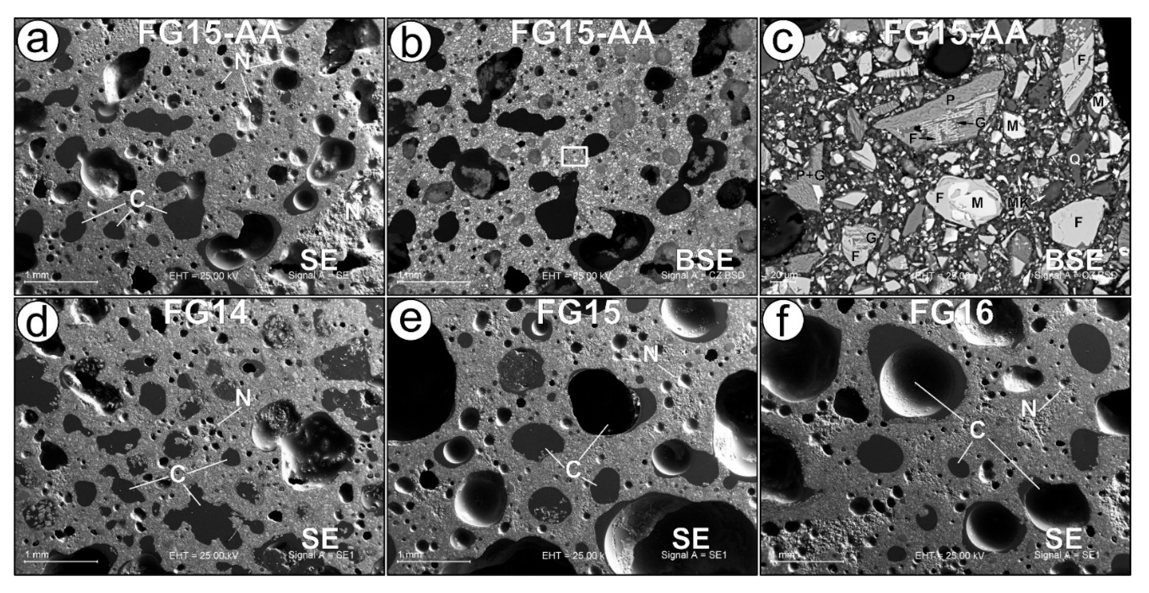
Figure 5.
Real size polished specimen (300 x 300 x 30 mm) based on series FG15-AA. Top surface (Left) and bottom surface (right).
Figure 5.
Real size polished specimen (300 x 300 x 30 mm) based on series FG15-AA. Top surface (Left) and bottom surface (right).
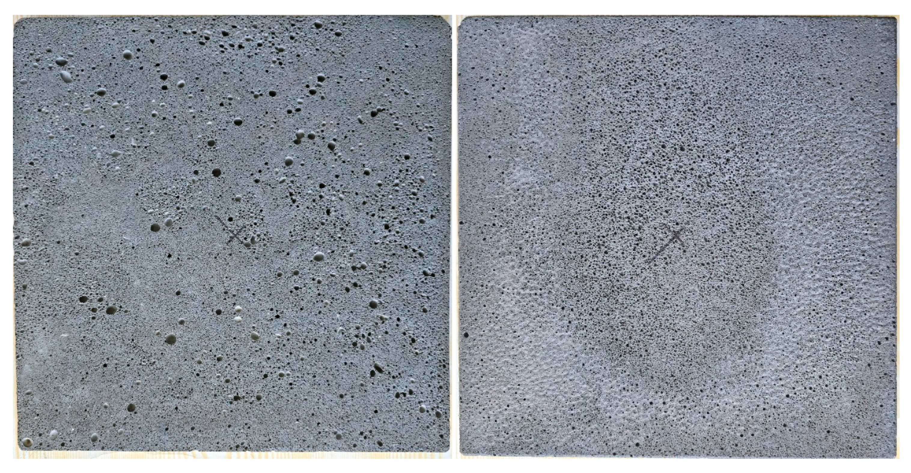
Figure 6.
Jet torch test (left) and the geopolymer foamed specimen after the fire test (right).
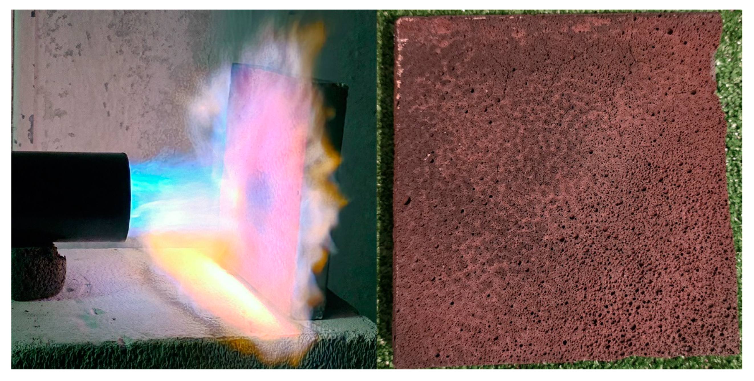
Table 1.
Chemical composition of the used fayalite slag and metakaolin as geopolymer precursors, according to XRF analysis, (in wt%).
Table 1.
Chemical composition of the used fayalite slag and metakaolin as geopolymer precursors, according to XRF analysis, (in wt%).
| Precursor | FeO | SiO2 | Al2O3 | CaO | ZnO | MgO | K2O | Na2O | CuO | PbO | TiO2 | MoO3 | SO3 |
|---|---|---|---|---|---|---|---|---|---|---|---|---|---|
| Fayalite | 55.83 | 31.16 | 4.67 | 2.82 | 1.40 | 0.95 | 0.75 | 0.62 | 0.52 | 0.39 | 0.32 | 0.29 | 0.28 |
| Metakaolin | 1.03 | 54.00 | 43.25 | 0.15 | n.d. | 0.09 | 0.62 | 0.11 | n.d. | n.d. | 0.74 | n.d. | 0.01 |
Disclaimer/Publisher’s Note: The statements, opinions and data contained in all publications are solely those of the individual author(s) and contributor(s) and not of MDPI and/or the editor(s). MDPI and/or the editor(s) disclaim responsibility for any injury to people or property resulting from any ideas, methods, instructions or products referred to in the content. |
© 2025 by the authors. Licensee MDPI, Basel, Switzerland. This article is an open access article distributed under the terms and conditions of the Creative Commons Attribution (CC BY) license (http://creativecommons.org/licenses/by/4.0/).
Copyright: This open access article is published under a Creative Commons CC BY 4.0 license, which permit the free download, distribution, and reuse, provided that the author and preprint are cited in any reuse.


