
Submitted:
31 March 2025
Posted:
01 April 2025
You are already at the latest version
Abstract
Nitrous oxide is a highly suitable oxidizer for hybrid rockets due to its self-pressurizing properties, moderate cost, and high accessibility. However, its vapor pressure and density are highly dependent on ambient temperature, requiring careful consideration of temperature variations in real applications. To mitigate this issue, an oxidizer called Nytrox was produced by simply adding a small fraction of oxygen to bulk nitrous oxide. This modification enables the hybrid rocket propulsion system to maintain a nearly constant average thrust and total impulse across a wide range of ambient temperatures. A series of 7-second hot-fire tests of a small Nytrox/ polypropylene hybrid rocket engine operating at ~60 barA of running tank pressure demonstrated a consistent average thrust of 45.3 ± 0.7 kgf and a total impulse of 307.6 ± 3.9 kgf·s within an N₂O temperature range of 5.9-22.6°C, compared to highly varying values of a N₂O/polypropylene one within an N₂O temperature range of 10.8-29.8°C. Furthermore, the specific impulse of the Nytrox hybrid rocket engine increases mildly with decreasing temperature because of the increasing amount of added oxygen that benefits the combustion for generating the thrust.
Keywords:
hybrid rocket
; nitrous oxide
; oxygen
; nytrox
; self-pressurizing
1. Introduction
The hybrid rocket propulsion system combines features of solid and liquid propulsion systems. Figure 1 shows the conceptual design of a hybrid rocket engine (hereafter HRE), in which the liquid or gaseous oxidizer flows into the combustion chamber, containing a solid fuel grain through a control valve and an oxidizer injector, for combustion and generates the designed thrust. Recently, due to its throttle ability, low-cost effectiveness, simplicity, reliability, and safety, hybrid rocket propulsion system has the potential as serving a future rocket propulsion system. Therefore, many commercial companies such as Gilmour in Australia, Innospace in South Korea, HyImpulse in Germany, and ATspace in Australia, to name a few, are currently developing satellite launch vehicles using the HREs as their primary propulsion system [1].
Among all possible oxidizer choices of hybrid rocket, nitrous oxide may become the preferred choice for relatively small rockets due to its self-pressurizing properties because of its high vapor pressure at normal temperature. A blow-down type with self-pressurizing system could achieve a high thrust in a simple and cost-effective way, because it reduces the additional weight, complexity, and cost of the pressurization system. For example, Virgin Galactic’s SpaceShip One was launched to an altitude of 90 km with a crew of three which was powered by an HRE using N2O and HTPB [2,3]. The Hybrid Engine Development (HyEnD) hybrid sounding rocket project at the University of Stuttgart has also presented several hybrid rockets using N2O as the oxidizer [4], and the N2ORTH sounding rocket reached an altitude of 64.4 km in 2023 [5]. The other important advantages of N2O include stable combustion, easy access commercially with a modest cost. However, the main disadvantage of N2O is that the vapor pressure and density highly depend on the ambient temperature (assuming it matches the temperature of N2O), as shown in Table 1 and Figure 2; this leads to an immense impact on the control of the injected mass flow rate and thrust in a blow-down system, hence impairing the stability of the propulsion performance, which is otherwise important for a real application [6].
To enhance the use of N2O as an oxidizer in hybrid rocket propulsion, Karabeyoglu et al. [8,9] introduced Nytrox - a nitrous oxide-oxygen mixture, which is designed for improved safety and easier preparation. In Nytrox, oxygen serves as the pressurizing agent, while N2O acts as the densifying component. Compared to its pure components, Nytrox offers a balanced combination of specific impulse performance, density, self-pressurization characteristics, chemical stability, storability, and ease of handling. Additional advantages include the ability to adjust the composition ratio based on mission requirements and enhanced gas-phase combustion efficiency. Moreover, Nytrox provides greater overall safety, as O2 acts as a diluent in gaseous N2O, increasing the activation energy required for self-decomposition.
Regarding the properties and practical applications of Nytrox, Whitmore et al. [10,11,12,13] explored the methods and conditions for its preparation and storage, and conducted a feasibility analysis on replacing gaseous O2 with Nytrox in hybrid motors for small spacecraft. Their research established a method for calculating the properties of Nytrox under various temperatures and pressures. In addition, the data (diagram format) of O2 dissolved mass fraction and density for saturated gas and liquid Nytrox at different pressures and temperatures were provided. Nytrox was produced by simply bubbling gaseous oxygen under high pressure into liquid nitrous oxide until the solution reaches saturation. The study showed that, while Nytrox has a slightly lower specific impulse and regression rate compared to pure gaseous oxygen, it offers a significantly higher volumetric efficiency.
Compared to conventional oxidizers, Nytrox retains the excellent self-pressurization characteristics of nitrous oxide while offering enhanced safety and cost benefits without sacrificing performance. Since the mixture composition is determined by two control variables—temperature and pressure—different Nytrox formulations have been explored in several studies and can be easily fine-tuned for specific applications. However, the primary drawback of Nytrox is the need to maintain a fixed oxidizer temperature, as the solubility of oxygen is highly dependent on the temperature of liquid N2O and the applied pressure.
An interesting concept is that during pressure variations in a running tank of a blowdown system additional oxygen is released from liquid nitrous oxide due to changes in oxygen solubility. This process generates a self-pressurization effect like N2O gasification. Since a lower temperature and a higher applied pressure of the nitrous oxide allow for larger oxygen dissolution, more oxygen is released as tank pressure fluctuates, enabling Nytrox to exhibit a similar blowdown pressure change curve across different temperature conditions.
This research aims to utilize Nytrox as an oxidizer to address the primary shortcomings of N2O-based hybrid rocket propulsion, specifically the sensitivity of thrust and total impulse performance under various ambient temperatures. A series of ground static hot-fire tests with the running tank operating at approximately 60 barA were performed using a swirling-injection small hybrid rocket engine with a single-port fuel grain. The test results of the thrust and total impulse were analyzed under N2O temperatures ranging from 5.9°C to 29.8°C, comparing both nitrous oxide (10.8°C to 29.8°C) and Nytrox (5.9°C to 22.6°C) as oxidizers. The goal is to achieve a stable thrust, a total impulse, and a specific impulse in this temperature range, simplifying future implementation in real applications of the propulsion technology.
2. Research Methods
This research is based on a 45 kgf thrust-level hybrid rocket propulsion system with swirling-injection oxidizer, and designed to utilize Nytrox oxidizer by incorporating an N2O and O2 filling system. Additionally, a theoretical model was developed to determine the liquid/gas mass ratio and oxygen solubility in nitrous oxide at known N2O temperatures and vapor pressures. This model was used to characterize the properties of the Nytrox, which then guided the assessment of the propulsion system’s available burn time and combustion performance. Subsequently, a series of horizontal ground static hot-fire tests were conducted using the propulsion system with different oxidizers (nitrous oxide and Nytrox) under various N2O temperature conditions. The differences in engine performance between the two oxidizers were then analyzed and compared. The detailed methods are described in the following.
2.1. Combustion Chamber Design and Specification
Figure 3 illustrates the cross-sectional view and overview of the combustion chamber used in this study. The oxidizer is injected into the combustion chamber through a swirling injector. The polypropylene (PP) solid fuel grain features a single-port design for simplicity of manufacturing. It has a cylindrical shape with an outer diameter of 80 mm, an initial inner diameter of 26 mm, and a length of 240 mm. Both ends of the grain have a tapered configuration, and a step is designed upstream of the fuel to create a recirculation zone, ensuring smooth engine ignition by a pyrograin igniter. The nozzle has a simple conical design, which is made of graphite, with a throat diameter of 10 mm and an expansion ratio of 6.25. This hybrid rocket engine is designed to produce a thrust of 45 kgf, a chamber pressure of 40 barA, an average oxidizer-to-fuel (O/F) ratio of 7 (based on pure N2O), and a specific impulse of 220 s.
This study utilizes a swirling oxidizer injector to generate a swirling flow field within the combustion chamber, enhancing the mixing of the oxidizer and fuel while improving the diffusion flame characteristics of hybrid combustion. To quantify the intensity of the swirling flow field produced by the oxidizer passing through the injector, Beer et al. [14] defined the geometric swirl number (SNg) based on the injector's geometric dimensions as follows:
where is the injector outlet radius, is the injector tangential inlet port radius, and N is the number of tangential inlet ports, as shown in Figure 6.
In this research, the geometric swirl number of the oxidizer injector is designed to be 58.5 due to its liquid state when injected into the chamber. The detailed geometric dimensions of the oxidizer injector are shown in Figure 7, and the geometric swirl number parameters are summarized in Table 2. Considering the injection angles of the tangential inlet ports in both the radial and axial directions, SNg is defined as follows:
where is the distance between the center of the tangential inlet port outlet and the axis, r is the distance from the center of the tangential inlet port inlet to the injector axis (), is the angle between the direction of the tangential inlet port and the axial direction, and is the angle between the direction of the tangential inlet port and the radial direction.
2.2. Theoretical Models for the Mixture of Liquid Nitrous Oxide and Oxygen
2.2.1. Determination of the Filling Method of Nitrous Oxide
When nitrous oxide is used as a rocket oxidizer, it is stored in a liquid-vapor coexisting state. Liquid nitrous oxide serves as the primary oxidizer entering the combustion chamber to participate in the combustion reaction, while the gaseous portion is utilized for pressurization. As shown in Figure 2, nitrous oxide has a specific saturated vapor pressure at different temperatures. By measuring the pressure and temperature inside the storage tank and comparing it with the available N2O properties, the corresponding densities of N2O in the gas and liquid phases in the storage tank can be determined. Taking 25°C as an example, the gas and liquid densities can be determined as 190 kg/m3 and 744 kg/m3, respectively, as illustrated in Figure 8.
Given the storage tank volume and the total mass of N2O filled into the storage tank , the filling volume ratio of liquid N2O and its corresponding weight can be calculated as follows:
Based on the target thrust , the specific impulse , and the O/F ratio, the required oxidizer mass flow rate can be estimated as follows:
Dividing the available liquid oxidizer mass by the mass flow rate yields the maximal burn time of the storage tank at that filling mass as follows:
Since nitrous oxide will vaporize during the operation of the blowdown process, the amount of usable liquid N2O () can be estimated by subtracting the mass of the fully vaporized N2O gas at the same temperature from the total filled N2O. It is important to note that Equation 7 is a simplified estimation only for convenience. In reality, as N2O vaporizes, its temperature decreases, leading to a lower gas density, which means that a higher amount of liquid nitrous oxide can be utilized. Additionally, because the density of N2O increases significantly with decreasing N2O temperature, the maximum amount that can be filled into the fixed-volume storage tank at lower temperatures is much higher than at higher temperatures. This also leads to an increase in maximal burn time.
To evaluate the impact of the N2O filling mass on the experimental parameters at different temperatures, this research employs the calculation method described above as a basis. Under the condition of a fixed storage tank volume of 2.8 liters and varying temperature conditions (expressed by N2O vapor pressure, with 60 barA as the benchmark and intervals of 5 bar downward to 40 barA), three filling methods are analyzed: the total filling mass of N2O (1.922 kg), the liquid N2O percentage (95%), and the maximum burn time (7.4 seconds). The results, as shown in Figure 9, indicate that the method of total filling mass of N2O provides a tradeoff solution among the three varying parameters. Compared to the other methods, it has a relatively small impact on the overall change of parameters. Additionally, the fixed filling mass method allows for easier measurement of the storage tank mass as a benchmark, simplifying the operational process and making it more intuitive. Therefore, this research adopts the method of fixed total filling mass of nitrous oxide as the filling approach for the formal tests.
2.2.2. Estimation of the Solubility of O2 in Liquid/Gaseous N2O
For the theoretical model of Nytrox, Karabeyoglu [8] employed the Peng-Robinson method to model the properties of Nytrox. Whitmore and Stoddard [10] also applied the same model to establish a method for calculating the properties of Nytrox at various temperatures and pressures. They developed mass fraction and density diagrams for O2 dissolved in both gaseous and liquid N2O at different pressures and temperatures. In this study, the O2 solubility data in the temperature range of 0°C to 30°C were extracted and replotted in Figure 10 in which the curves are presented as isotherms in vapor phase (Figure 10a) and liquid phase (Figure 10b), respectively. For example, by measuring the actual temperature and pressure in the running tank and referring to the corresponding temperature and pressure solubility plot in Figure 10(b), the mass fraction of O2 in the liquid-phase mixture can be readily obtained. A typical procedure for estimating the oxygen mass fraction in the liquid is illustrated in Figure 11. For example, the N2O temperature is 11.3°C and gaseous O2 is bubbled into the liquid N2O to reach a pressure of 60.4 barA. Then, the mass fraction of O2 in the liquid N2O can be determined as 4.4%. This is obtained by interpolating data between two isotherms (10°C and 20°C).
2.3. Experimental Facility and Instrumentation
Figure 12 shows the oxidizer filling and feeding system for the ground static hot-fire tests of the nitrous oxide and Nitrox hybrid rocket engine. It consists of a running tank with an integrated mass load cell, an N2O and O2 filling system, a nitrogen cooling pipeline, multiple pressure transducers, many K-type thermocouples for monitoring the running tank and pipeline, a load cell for measuring instantaneous thrust, and an open-loop control valve capable of delivering both low and full flow rates of oxidizer, respectively, for ignition and hot-fire burning. All test procedures were automated using pre-programmed software on a DAQ system (Model No. cRIO-9074, National Instruments).
2.4. Experimental Configuration and Procedure
To establish suitable oxidizer configurations and effectively control experimental parameters, this study maintained a consistent N2O filling mass. For the Nytrox tests, the gaseous O2 was bubbled under high pressure into liquid N2O to form the Nytrox until a predetermined target pressure of 60 barA was reached. The varying parameters of the hot-fire test included the oxidizer type (N2O/Nytrox) and the N2O temperature in the range of 5.9-29.8 °C. It is important to note that the venting process influenced the N2O temperature during the filling procedure. The N2O filling mass was fixed as 1.922 kg, corresponding to 95% of the N2O liquid-phase volume within the fixed tank volume (2.8 L) at an N2O temperature of 28°C. This filling mass provided an approximate combustion duration of 7.4 seconds at a constant temperature and oxidizer mass flow rate. The target tank pressure for the Nytrox tests was set to 60 barA, closely matching the vapor pressure of pure N2O at 28°C. This approach served two purposes: first, it facilitated a performance comparison with pure N2O at an N2O temperature of 28°C; second, it simplified implementation by providing a clear benchmark.
Figure 13 illustrates the automated procedural sequence of the ignition voltage for ignition of the pyrograin and the valve angle for controlling the flow rate of the oxidizer, with and the corresponding flame images shown in Figure 14. Upon initiating the automated procedure, the ignition signal was activated for one second, igniting the pyro grain igniter via the electronic ignition system. Subsequently, the control valve was opened to the preheat angle, delivering an approximate oxidizer flow rate of 10 g/s to ignite the solid fuel and preheat the combustion chamber. Following preheating, the control valve was fully opened and maintained for four seconds. Finally, the control valve was rapidly closed within approximately 0.2 seconds, and the nitrogen gas cooling valve was opened, injecting cold nitrogen gas into the combustion chamber to extinguish any residual flames.
3. Results and Discussion
3.1. Analysis of Pure Nitrous Oxide HRE Hot-Fire Test Results
Figure 15 illustrates the measured temporal variations of tank pressure, chamber pressure, and thrust in two ground hot-fire tests using pure N2O at the highest (29.8°C, vapor pressure 63.1 barA) and the lowest (10.8°C, vapor pressure 40.9 barA) N2O temperatures, respectively. Table 3 compares the propulsion performance of these pure N2O hot-fire tests. The data clearly demonstrate the significant influence of ambient temperature on the performance of pure N2O hybrid rocket propulsion system. A decrease in N2O vapor pressure with decreasing temperature leads to an obvious reduction of the self-pressurized vapor pressure, and thus resulting in reduced combustion pressure. It naturally leads to a reduced thrust, a total impulse, and an average sea-level Isp at the same time. These findings underscore the importance of taking into account the variation of ambient temperature in the design and operation of N2O hybrid rocket systems, necessitating the design of an auxiliary pressurization system or regulating the temperature of N2O across different ambient conditions to maintain upstream pressure stability without too much engineering work required.
3.2. Analysis of Nytrox HRE Hot-Fire Test Results
Figure 16 illustrates the temporal variations of tank pressure, chamber pressure, and thrust in two ground static hot-fire tests using the Nytrox oxidizer at the highest (22.6°C, vapor pressure 53.6 barA) and the lowest (5.9°C, vapor pressure 36.3 barA) N2O temperatures, respectively. Table 4 summarizes the comparison of the propulsion performance of the Nytrox hot-fire tests. The Nytrox test results indicate that the addition of O2 to N2O and pressurization to a consistent tank pressure of 60 barA greatly improved the stability and consistency of the hybrid rocket propulsion system. The minimal variation in tank pressure produced a similar engine performance variation. In the contrast with pure N2O tests, the combustion pressure, the thrust, and the total impulse exhibited greatly reduced sensitivity to the variation of N2O vapor pressure due to different ambient temperatures. The coefficients of variation for the combustion chamber pressure, the thrust, and the total impulse were calculated as 1.9%, 1.0%, and 1.1%, respectively. In addition, the coefficient of variation for the average sea-level Isp was only 2.3%, indicating similar performance was observed.
Figure 17 and Figure 18 illustrate the average thrust and total impulse data, respectively, using two different oxidizers with varying N2O vapor pressures due to different N2O temperatures during the hot-fire tests. The results indicate that the thrust and total impulse of pure N2O tests exhibit an almost linear regression with the N2O vapor pressure (pure N2O in this case), whereas the Nytrox tests maintained a nearly constant thrust (45.3 ± 0.7 kgf) and total impulse (307.6 ± 3.9 kgf·s) in the range of N2O vapor pressures (N2O with a small fraction of O2 in this case) tested. The trending lines of both oxidizers (N2O and Nytrox) converge near the target O2 pressurization pressure (~60 barA), suggesting that deviations in O2 pressurization pressure during Nytrox preparation would result in total impulse and thrust values approaching those of pure N2O result at the same tank pressure. It should be noted that, the initial tank pressure of the Nytrox system was 60.4 ± 0.4 barA, while the initial tank pressure of the pure N2O system matches its vapor pressure.
Furthermore, Figure 19 compares the average sea-level specific impulse of the pure N2O and the Nytrox hot-fire tests with varying N2O vapor pressures. The results indicate that a positive correlation for pure N2O tests. Conversely, a negative correlation was observed for the specific impulse of the Nytrox tests in the range of N2O vapor pressures tested. This discrepancy arises because the lower the tank N2O temperature is the N2O vapor pressure is the lower N2O vapor pressure is the higher the O2 solubility is, as shown in Figure 10. The more the dissolved O2 in the liquid oxidizer the better the combustion performance is, while the O2 released from the Nytrox liquid helps maintain tank supply pressure automatically. This allows the combustion chamber pressure to remain at the optimal value for the nozzle design, thereby improving the overall theoretical Isp. These findings confirm that the Nytrox approach effectively improves and stabilizes the performance of N2O-based hybrid rocket propulsion system. Moreover, an experimentally observed trend indicates that the lower the N2O temperature is the better the Nytrox hybrid rocket engine performance is.
4. Conclusions
In this study, we investigate the effect of ambient temperature on the performance of an N2O hybrid rocket propulsion system and explores the use of the Nytrox as an oxidizer to enhance and stabilize its propulsion performance. To achieve this goal, a propellant feed system capable of preparing and utilizing both pure N2O and Nytrox was developed, and multiple static hot-fire tests were conducted at various N2O temperatures using both oxidizers. The major findings are summarized as follows:
1. For a consistent engine burn time, the thrust, total impulse, and specific impulse of a pure N2O hybrid rocket propulsion system exhibits an almost linear relation with N2O vapor pressure, which is highly dependent on the N2O temperature.
2. By bubbling gaseous O2 under high pressure into liquid N2O to prepare the Nytrox as an oxidizer in a hybrid rocket propulsion system while maintaining a consistent running tank pressure, a nearly constant average thrust and total impulse can be achieved with various N2O temperatures.
3. As the temperature of N2O decreases and the O2 fill ratio increases, the HRE’s specific impulse increases accordingly.
In summary, under consistent oxidizer running tank pressure conditions, a simple bubbling gaseous oxygen into the liquid nitrous oxide allows for adjusting the target engine thrust level by modifying the target oxygen pressurization pressure. In addition, this approach enables the HRE to maintain a stable average thrust and total impulse across a wide range of N2O temperatures (5.9-22.6 °C). These characteristics significantly contribute to system simplification and enhance the applicability of the Nytrox in real applications, e.g., sounding rockets, with different mission requirements.
Acknowledgments
This research was supported by the National Science and Technology Council, Taiwan, through the grant MOST-107-2218-E-009-054 and MOST-108-2218-E-009-030 and MOST-109-2224-E-009 -001, and the Advanced Rocket Research Center of National Yang Ming Chiao Tung University, Taiwan, through the grant Q590003. Finally, many generous donations from numerous private companies and citizens in Taiwan for supporting this project are also highly appreciated.
References
- Wei, S.S.; Li, M.C.; Lai, A.; Chou, T.H.; Wu, J.S. A Review of Recent Developments in Hybrid Rocket Propulsion and Its Applications. Aerospace 2024, 11, 739. [Google Scholar] [CrossRef]
- Kelly, J.W.; Rogers, C.E.; Brierly, G.T.; Martin, J.C.; Murphy, M.G. Motivation for Air-Launch: Past, Present, and Future. In Proceedings of the AIAA SPACE and Astronautics Forum and Exposition, Orlando, FL, USA, 12–14 September 2017. [Google Scholar]
- Thicksten, Z.; Macklin, F.; Campbell, J. Handling Considerations of Nitrous Oxide in Hybrid Rocket. In Proceedings of the 44th AIAA/ASME/SAE/ASEE Joint Propulsion Conference and Exhibit, Hartford, CT, USA, 21–23 July 2008. [Google Scholar]
- Kobald, M.; Schmierer, C.; Fischer, U.; Tomilin, T.; Petrarolo, A.; Rehberger, M. The HyEnD Stern Hybrid Sounding Rocket Project. Prog. Propuls. Phys. 2019, 11, 25–64. [Google Scholar]
- Hybrid Engine Development. First Results of the N2ORTH Post Flight Analysis. Available online: https://hyend.de/index.php/2023/07/18/first-results-of-the-n2orth-post-flight-analysis/ (accessed on 8 September 2024).
- Zakirov, V.; Sweeting, M.; Lawrence, T.; Sellers, J. Nitrous Oxide as a Rocket Propellant. Acta Astronaut. 2001, 48, 353–362. [Google Scholar] [CrossRef]
- ESDU, Thermophysical Properties of Nitrous Oxide, 1991.
- Karabeyoglu, A. Mixtures of Nitrous Oxide and Oxygen (Nytrox) as Oxidizers for Rocket Propulsion Applications. In Proceedings of the 45th AIAA/ASME/SAE/ASEE Joint Propulsion Conference and Exhibit, Denver, CO, USA, 2–5 August 2009. [Google Scholar]
- Karabeyoglu, A. Nitrous Oxide and Oxygen Mixtures (Nytrox) as Oxidizers for Rocket Propulsion Applications. J. Propuls. Power 2014, 30, 696–706. [Google Scholar] [CrossRef]
- Whitmore, S.A.; Stoddard, R.L. Medical Grade N2O/O2 Mixtures as Inexpensive and Volumetrically Efficient Oxidizers for Small Spacecraft Hybrid Propulsion Systems. In Proceedings of the AIAA Propulsion and Energy 2019 Forum, Indianapolis, IN, USA, 19–22 August 2019. [Google Scholar]
- Whitmore, S.A. Nytrox as “Drop-in” Replacement for Gaseous Oxygen in SmallSat Hybrid Propulsion Systems. Aerospace 2020, 7, 43. [Google Scholar] [CrossRef]
- Whitmore, S.A.; Stoddard, R.L. N2O/O2 blends safe and volumetrically efficient oxidizers for small spacecraft hybrid propulsion. Aeronaut. Aerosp. Open Access J. 2019, 3, 171–196. [Google Scholar] [CrossRef]
- Whitmore, S.A.; Frischkorn, C.I. Analyzing and Reducing Ignition Latency of a Nytrox/ABS Hybrid Propulsion System. In Proceedings of the AIAA Propulsion and Energy 2020 Forum, Online, 24–28 August 2020. [Google Scholar]
- Beer, J.M.; Chigier, N.A. Combustion Aerodynamics; Applied Science Publishers: London, 1972. [Google Scholar]
Figure 1.
Hybrid rocket propulsion system schematic.
Figure 2.
N2O properties respect to temperature. [7].
Figure 2.
N2O properties respect to temperature. [7].
Figure 3.
The cross-sectional schematic of combustion chamber.
Figure 6.
Schematic of a typical swirl injector (N=4).
Figure 7.
The swirling injector design schematic of this research.
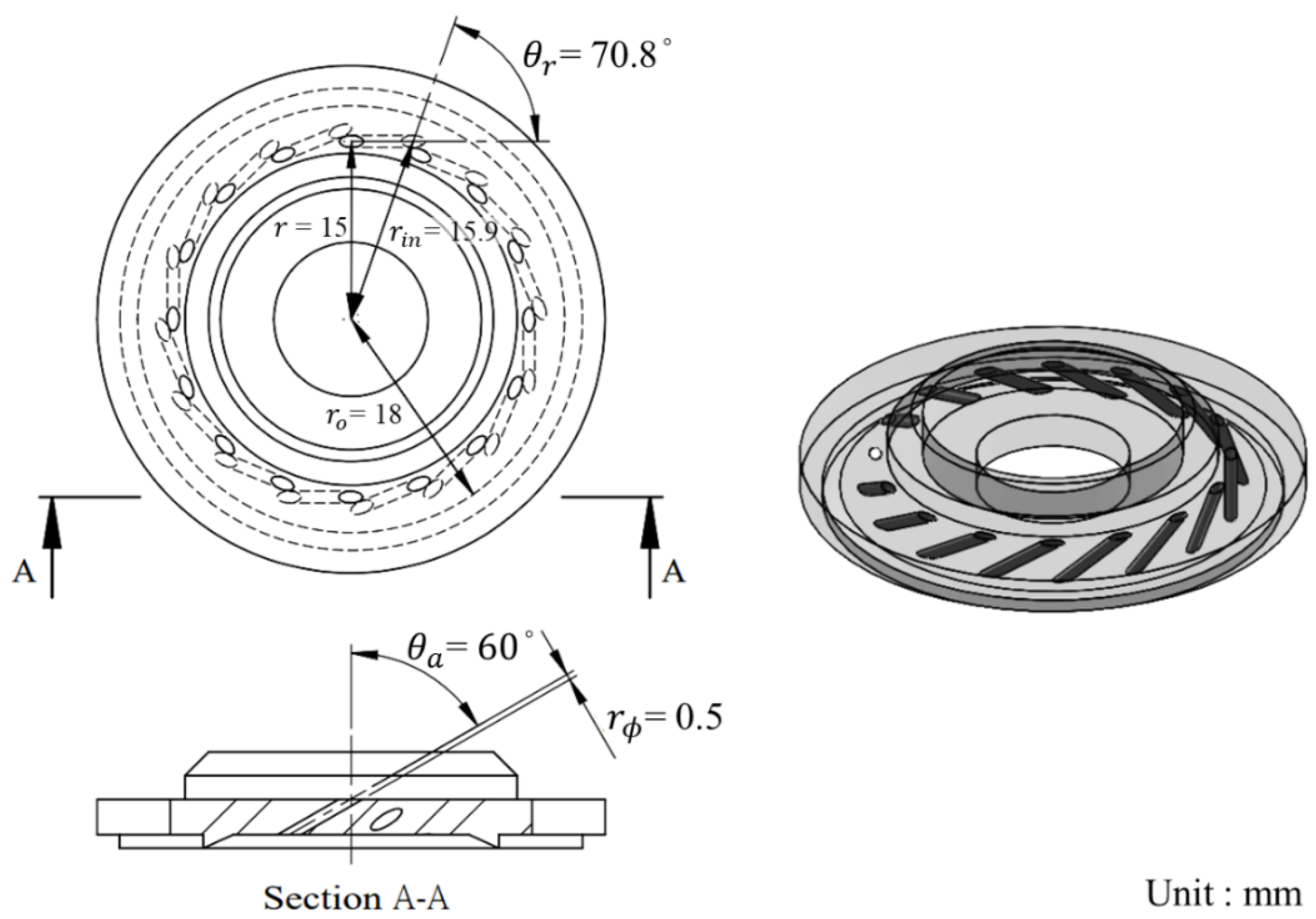
Figure 8.
Query density using the N2O properties diagram.
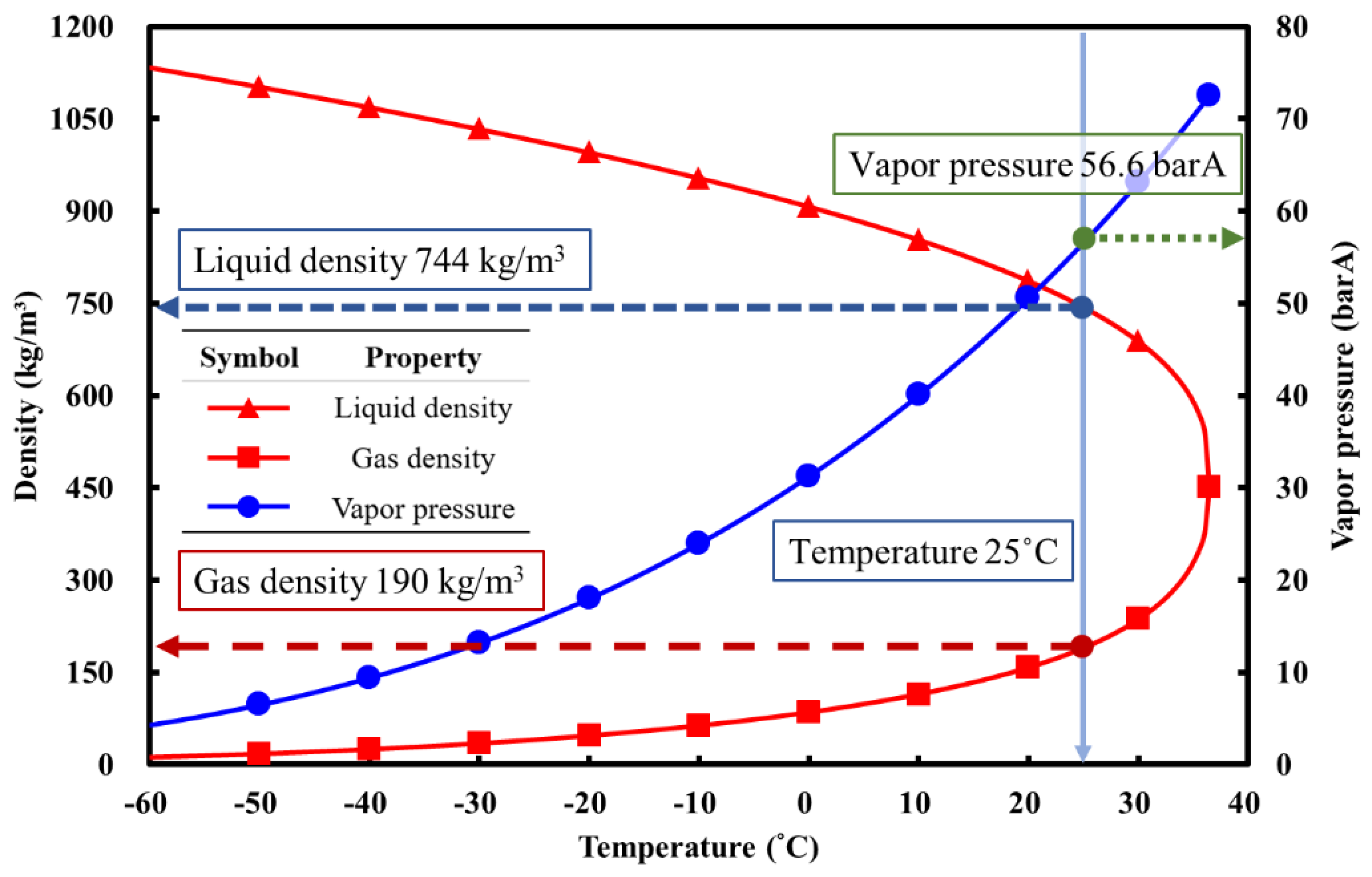
Figure 9.
Comparison of three filling methods under various vapor N2O pressures. (a) the total filling mass of N2O (b) the percentage of liquid N2O (c) the maximum burn time.
Figure 9.
Comparison of three filling methods under various vapor N2O pressures. (a) the total filling mass of N2O (b) the percentage of liquid N2O (c) the maximum burn time.
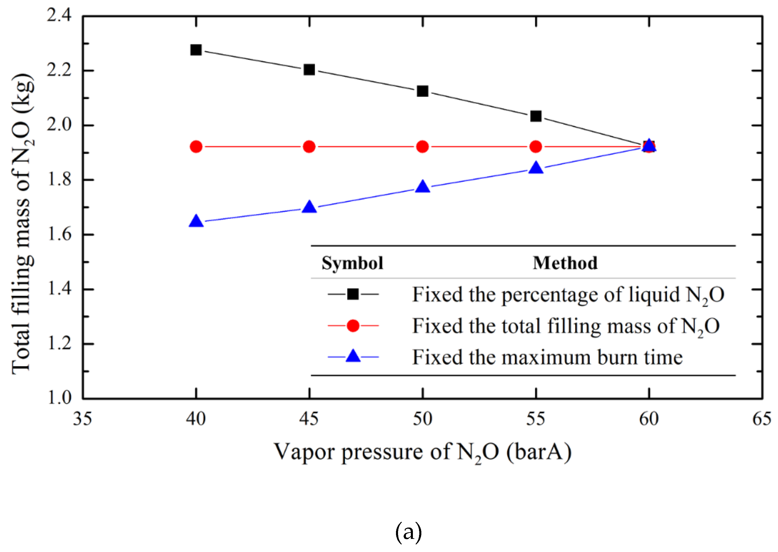
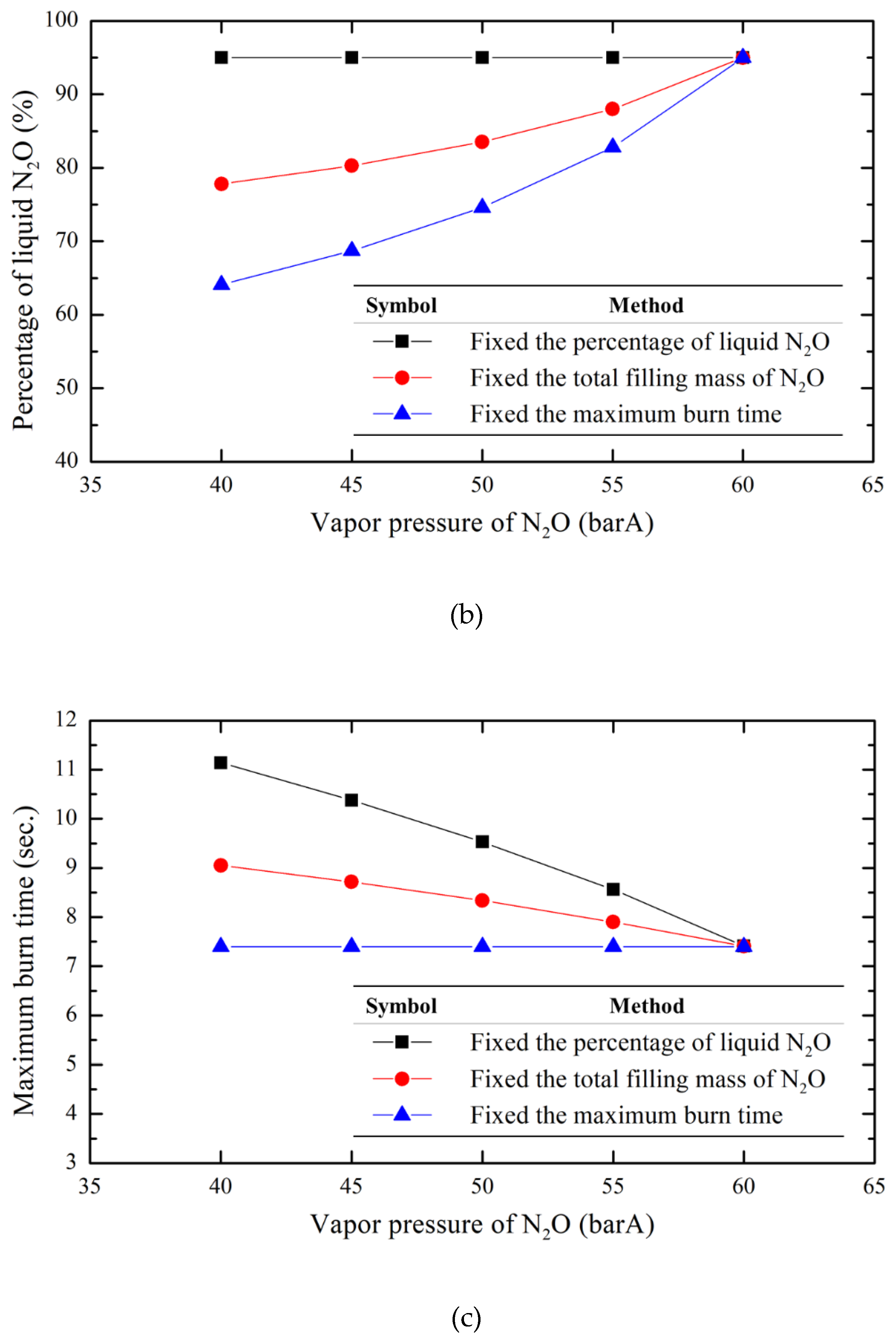
Figure 10.
Isotherm plots for a saturated N2O/O2 solution in (a) vapor (b) liquid phase.
Figure 11.
An example for calculating the mass fraction of O2 in the liquid mixture using interpolation (example condition: tank pressure of 60 barA and N2O of 11.3°C).
Figure 11.
An example for calculating the mass fraction of O2 in the liquid mixture using interpolation (example condition: tank pressure of 60 barA and N2O of 11.3°C).
Figure 12.
System diagram of the ground static hot-fire test.
Figure 13.
The automatic process profile of the hot-fire test.
Figure 14.
The flame images during the tests at different stages: (a) ignition, (b) preheating, (c) control valve opening process, (d) control valve fully open, (e) flameout and cooling.
Figure 14.
The flame images during the tests at different stages: (a) ignition, (b) preheating, (c) control valve opening process, (d) control valve fully open, (e) flameout and cooling.
Figure 15.
Measured temporal data of the tank pressure, chamber pressure and thrust of the hot-fire tests of the pure N2O HRE with different N2O temperatures (10.8 °C and 29.8 °C).
Figure 15.
Measured temporal data of the tank pressure, chamber pressure and thrust of the hot-fire tests of the pure N2O HRE with different N2O temperatures (10.8 °C and 29.8 °C).
Figure 16.
Measured temporal data of the tank pressure, chamber pressure and thrust of the hot-fire tests of the Nytrox HRE with different N2O temperatures (5.9 °C and 22.6 °C).
Figure 16.
Measured temporal data of the tank pressure, chamber pressure and thrust of the hot-fire tests of the Nytrox HRE with different N2O temperatures (5.9 °C and 22.6 °C).
Figure 17.
Average thrust comparison using two different oxidizers as a function of N2O vapor pressures.
Figure 17.
Average thrust comparison using two different oxidizers as a function of N2O vapor pressures.
Figure 18.
Average total impulse comparison using two different oxidizers as a function of N2O vapor pressures.
Figure 18.
Average total impulse comparison using two different oxidizers as a function of N2O vapor pressures.
Figure 19.
Average specific impulse comparison using two different oxidizers at varying N2O vapor pressures.
Figure 19.
Average specific impulse comparison using two different oxidizers at varying N2O vapor pressures.

Table 1.
N2O properties respect to temperature. [7].
Table 1.
N2O properties respect to temperature. [7].
| Temperature (°C) | Vapor pressure (barA) | Liquid density (kg/m3) | Vapor density (kg/m3) |
| -20 | 18.01 | 995.4 | 46.82 |
| -15 | 20.83 | 975.2 | 54.47 |
| -10 | 23.97 | 953.9 | 63.21 |
| -5 | 27.44 | 931.4 | 73.26 |
| 0 | 31.27 | 907.4 | 84.86 |
| 5 | 35.47 | 881.6 | 98.41 |
| 10 | 40.07 | 853.5 | 114.5 |
| 15 | 45.10 | 822.2 | 133.9 |
| 20 | 50.60 | 786.6 | 158.1 |
| 25 | 56.60 | 743.9 | 190.0 |
| 30 | 63.15 | 688.0 | 236.7 |
| 35 | 70.33 | 589.4 | 300.4 |
| Tcrit (36.42 °C) | 72.51 | 452.0 | 452.0 |
Table 2.
The design parameters of the swirling injector.
| Parameter | Value | Unit |
| N | 16 | - |
| 0.5 | mm | |
| 15 | mm | |
| 70.8 | ° | |
| 60 | ° | |
| 18 | mm | |
| 15.9 | mm | |
| SNg | 58.5 | - |
Table 3.
Comparison of pure N2O HRE hot-fire tests at different N2O temperatures.
| N2O vapor pressure (barA) | 40.9 | 45.5 | 48.5 | 52.4 | 58.0 | 63.1 |
| Tank pressure before test (barA) | 40.9 | 45.5 | 48.5 | 52.4 | 58.0 | 63.1 |
| Avg. chamber pressure (barA) | 26.2 | 31.7 | 34.1 | 35.5 | 38.3 | 41.6 |
| Total impulse (kgf·s) | 188.1 | 228.4 | 249.8 | 259.5 | 284.8 | 314.3 |
| Avg. thrust (kgf) | 26.7 | 33.8 | 35.9 | 38.5 | 43.6 | 45.0 |
| Avg. Isp at sea level (s) | 193.3 | 205.3 | 211.7 | 203.2 | 215.6 | 216.5 |
| Liquid N2O temperature (°C) | 10.8 | 14.9 | 18.1 | 21.5 | 26.3 | 29.8 |
Table 4.
Comparison of Nytrox HRE hot-fire tests at different N2O temperature.
| N2O vapor pressure (barA) | 36.3 | 41.3 | 46.0 | 48.0 | 53.6 |
| Tank pressure before test (barA) | 60.6 | 60.4 | 60.0 | 60.8 | 60.6 |
| Avg. chamber pressure (barA) | 37.3 | 38.4 | 37.8 | 37.1 | 38.8 |
| Total impulse (kgf·s) | 310.7 | 306.2 | 305.9 | 311.7 | 303.7 |
| Avg. thrust (kgf) | 45.3 | 45.1 | 45.7 | 45.6 | 44.6 |
| Avg. Isp at sea level (s) | 229.1 | 222.6 | 227.1 | 216.7 | 219.2 |
| Liquid N2O temperature (°C) | 5.9 | 11.3 | 15.9 | 18.3 | 22.6 |
| Dissolved O2 mass fraction of Nytrox (%) | 2.9 | 2.7 | 2.6 | 2.2 | 1.2 |
Disclaimer/Publisher’s Note: The statements, opinions and data contained in all publications are solely those of the individual author(s) and contributor(s) and not of MDPI and/or the editor(s). MDPI and/or the editor(s) disclaim responsibility for any injury to people or property resulting from any ideas, methods, instructions or products referred to in the content. |
© 2025 by the authors. Licensee MDPI, Basel, Switzerland. This article is an open access article distributed under the terms and conditions of the Creative Commons Attribution (CC BY) license (http://creativecommons.org/licenses/by/4.0/).
Copyright: This open access article is published under a Creative Commons CC BY 4.0 license, which permit the free download, distribution, and reuse, provided that the author and preprint are cited in any reuse.


